Embed Size (px)
Citation preview

Type 2 ModelsType 2 ModelsType 2 Models
Form# 45030-0120090911©2009 Hunter Fan Co.
For Your Records andWarranty AssistanceFor reference, also attach your receipt or a copyof your receipt to the manual.
__________________________________________Model Name
__________________________________________Model No.
__________________________________________Date Purchased
__________________________________________Where Purchased
EnglishEspañol
Owner’s Guide and Installation Manual

2
45030-01 • 09/11/09 • Hunter Fan Company
Table Of Contents
1 • Getting Ready . . . . . . . . . . . . . . . . . . . . . . 4
2 • Installing the Ceiling Plate . . . . . . . . . . 5
3 • Assembling and Hanging the Fan . . . 6
4 • Wiring the Fan . . . . . . . . . . . . . . . . . . . . . 7
5 • Installing the Canopy and Canopy Trim Ring . . . . . . . . . . . . . . . . . . . . . . . . . 8
6 • Assembling the Blades . . . . . . . . . . . . . . 9
7 • Completing Your Installation With or Without a Bowl Light Fixture . . . . . . 10
8 • Operating and Cleaning Your Ceiling Fan . . . . . . . . . . . . . . . . . . . . . . . . . . . . . . . 14
9 • Troubleshooting . . . . . . . . . . . . . . . . . . . . 15
© 2009 Hunter Fan Company
Your new Hunter® ceiling fan is an addition to your home or office that will provide comfort and performance for many years. This installation and operation manual gives you complete instructions for installing and operating your fan.
We are proud of our work. We appreciate the opportunity to supply you with the best ceiling fan available anywhere in the world.
Before installing your fan, for your records and warranty assistance, record information from the carton and Hunter nameplate label (located on the top of the fan motor housing).
Cautions and Warnings• READ THIS ENTIRE MANUAL CAREFULLY BEFORE BEGINNING
INSTALLATION. SAVE THESE INSTRUCTIONS.• Use only Hunter replacement parts.• To reduce the risk of personal injury, attach the fan directly to the
support structure of the building according to these instructions, and use only the hardware supplied.
• To avoid possible electrical shock, before installing your fan, disconnect the power by turning off the circuit breakers to the outlet box and associated wall switch location. If you cannot lock the circuit breakers in the off position, securely fasten a prominent warning device, such as a tag, to the service panel.
• All wiring must be in accordance with national and local electrical codes and ANSI/NFPA 70. If you are unfamiliar with wiring, use a qualified electrician.
• To reduce the risk of personal injury, do not bend the blade attachment system when installing, balancing, or cleaning the fan. Never insert foreign objects between rotating fan blades.
• To reduce the risk of fire, electrical shock, or motor damage, do not use a solid-state speed control with this fan. Use only Hunter speed controls.
Welcome
3
45030-01 • 09/11/09 • Hunter Fan Company
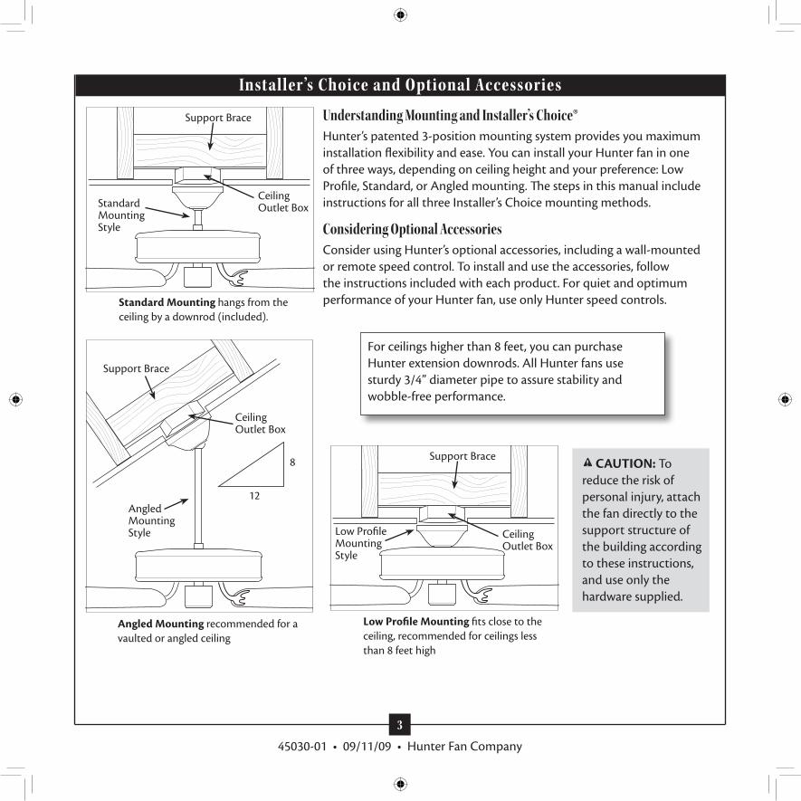
Understanding Mounting and Installer’s Choice®Hunter’s patented 3-position mounting system provides you maximum installation flexibility and ease. You can install your Hunter fan in one of three ways, depending on ceiling height and your preference: Low Profile, Standard, or Angled mounting. The steps in this manual include instructions for all three Installer’s Choice mounting methods.
Considering Optional AccessoriesConsider using Hunter’s optional accessories, including a wall-mounted or remote speed control. To install and use the accessories, follow the instructions included with each product. For quiet and optimum performance of your Hunter fan, use only Hunter speed controls.
For ceilings higher than 8 feet, you can purchase Hunter extension downrods. All Hunter fans use sturdy 3/4” diameter pipe to assure stability and wobble-free performance.
Standard Mounting hangs from the ceiling by a downrod (included).
Angled Mounting recommended for a vaulted or angled ceiling
Support Brace
Standard Mounting Style
Ceiling Outlet Box
Support Brace
Ceiling Outlet Box
Angled Mounting Style
Low Profile Mounting fits close to the ceiling, recommended for ceilings less than 8 feet high
Support Brace
Low Profile Mounting Style
Ceiling Outlet Box
8
12
CAUTION: To reduce the risk of personal injury, attach the fan directly to the support structure of the building according to these instructions, and use only the hardware supplied.
Installer’s Choice and Optional Accessories
4
45030-01 • 09/11/09 • Hunter Fan Company
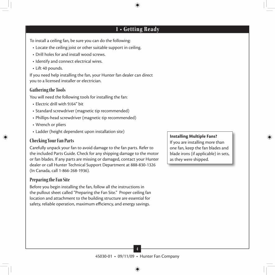
To install a ceiling fan, be sure you can do the following:
• Locate the ceiling joist or other suitable support in ceiling.
• Drill holes for and install wood screws.
• Identify and connect electrical wires.
• Lift 40 pounds.
If you need help installing the fan, your Hunter fan dealer can direct you to a licensed installer or electrician.
Gathering the ToolsYou will need the following tools for installing the fan:
• Electric drill with 9/64” bit
• Standard screwdriver (magnetic tip recommended)
• Phillips-head screwdriver (magnetic tip recommended)
• Wrench or pliers
• Ladder (height dependent upon installation site)
Checking Your Fan PartsCarefully unpack your fan to avoid damage to the fan parts. Refer to the included Parts Guide. Check for any shipping damage to the motor or fan blades. If any parts are missing or damaged, contact your Hunter dealer or call Hunter Technical Support Department at 888-830-1326 (In Canada, call 1-866-268-1936).
Preparing the Fan SiteBefore you begin installing the fan, follow all the instructions in the pullout sheet called “Preparing the Fan Site.” Proper ceiling fan location and attachment to the building structure are essential for safety, reliable operation, maximum efficiency, and energy savings.
Installing Multiple Fans?If you are installing more than one fan, keep the fan blades and blade irons (if applicable) in sets, as they were shipped.
1 • Getting Ready
5
45030-01 • 09/11/09 • Hunter Fan Company
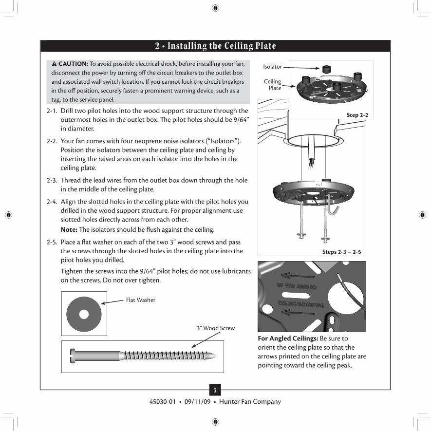
CAUTION: To avoid possible electrical shock, before installing your fan, disconnect the power by turning off the circuit breakers to the outlet box and associated wall switch location. If you cannot lock the circuit breakers in the off position, securely fasten a prominent warning device, such as a tag, to the service panel.
2-1. Drill two pilot holes into the wood support structure through the outermost holes in the outlet box. The pilot holes should be 9/64” in diameter.
2-2. Your fan comes with four neoprene noise isolators (“Isolators”). Position the isolators between the ceiling plate and ceiling by inserting the raised areas on each isolator into the holes in the ceiling plate.
2-3. Thread the lead wires from the outlet box down through the hole in the middle of the ceiling plate.
2-4. Align the slotted holes in the ceiling plate with the pilot holes you drilled in the wood support structure. For proper alignment use slotted holes directly across from each other.
Note: The isolators should be flush against the ceiling.
2-5. Place a flat washer on each of the two 3” wood screws and pass the screws through the slotted holes in the ceiling plate into the pilot holes you drilled.
Tighten the screws into the 9/64” pilot holes; do not use lubricants on the screws. Do not over tighten.
Step 2-2
Flat Washer
3” Wood Screw
Steps 2-3 – 2-5
For Angled Ceilings: Be sure to orient the ceiling plate so that the arrows printed on the ceiling plate are pointing toward the ceiling peak.
Ceiling Plate
Isolator
2 • Installing the Ceiling Plate
6
45030-01 • 09/11/09 • Hunter Fan Company
Steps 3-5 – 3-6
Low Profile Screw
Low Profile Washer
Steps 3-2 – 3-3
Downrod
Canopy
Canopy Trim Ring
Setscrew
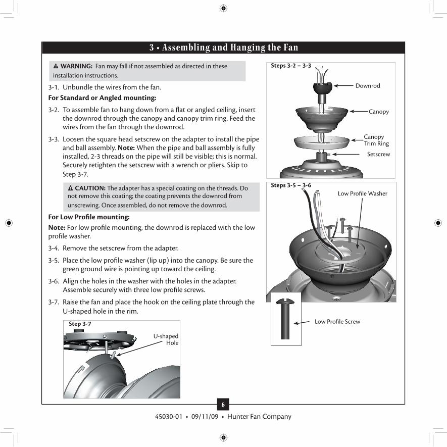
WARNING: Fan may fall if not assembled as directed in these installation instructions.
3-1. Unbundle the wires from the fan.For Standard or Angled mounting:
3-2. To assemble fan to hang down from a flat or angled ceiling, insert the downrod through the canopy and canopy trim ring. Feed the wires from the fan through the downrod.
3-3. Loosen the square head setscrew on the adapter to install the pipe and ball assembly. Note: When the pipe and ball assembly is fully installed, 2-3 threads on the pipe will still be visible; this is normal. Securely retighten the setscrew with a wrench or pliers. Skip to Step 3-7.
CAUTION: The adapter has a special coating on the threads. Do not remove this coating; the coating prevents the downrod from unscrewing. Once assembled, do not remove the downrod.
For Low Profile mounting:Note: For low profile mounting, the downrod is replaced with the low profile washer.
3-4. Remove the setscrew from the adapter.
3-5. Place the low profile washer (lip up) into the canopy. Be sure the green ground wire is pointing up toward the ceiling.
3-6. Align the holes in the washer with the holes in the adapter. Assemble securely with three low profile screws.
3-7. Raise the fan and place the hook on the ceiling plate through the U-shaped hole in the rim.
Step 3-7
U-shaped Hole
3 • Assembling and Hanging the Fan
7
45030-01 • 09/11/09 • Hunter Fan Company
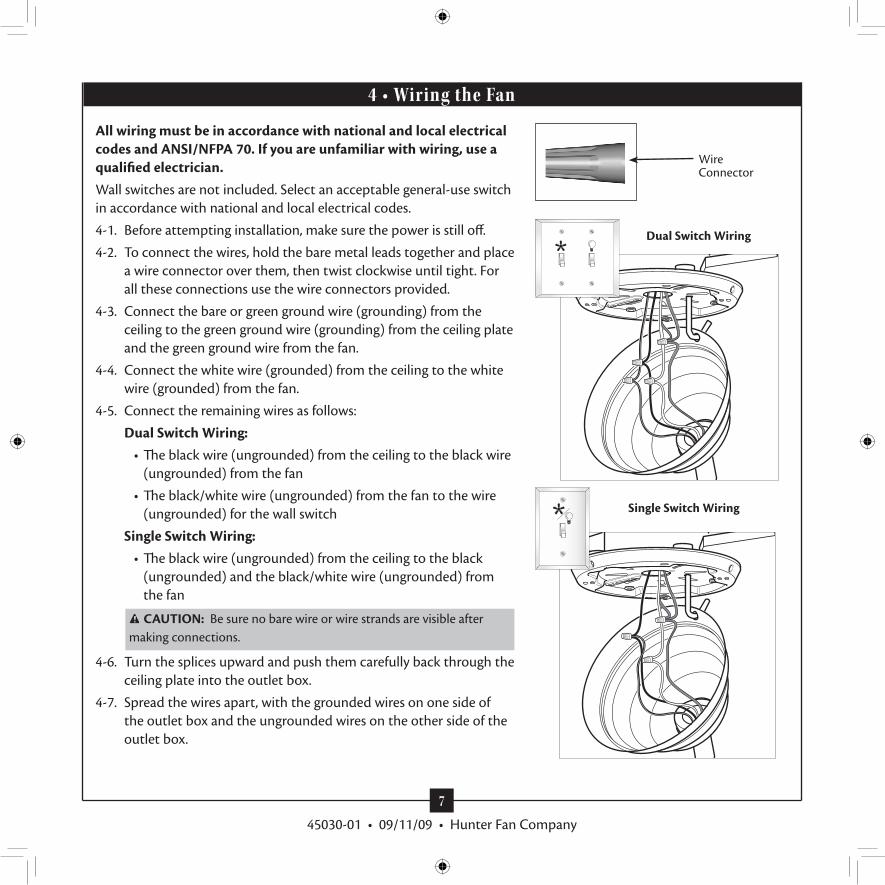
All wiring must be in accordance with national and local electrical codes and ANSI/NFPA 70. If you are unfamiliar with wiring, use a qualified electrician.Wall switches are not included. Select an acceptable general-use switch in accordance with national and local electrical codes.
4-1. Before attempting installation, make sure the power is still off.
4-2. To connect the wires, hold the bare metal leads together and place a wire connector over them, then twist clockwise until tight. For all these connections use the wire connectors provided.
4-3. Connect the bare or green ground wire (grounding) from the ceiling to the green ground wire (grounding) from the ceiling plate and the green ground wire from the fan.
4-4. Connect the white wire (grounded) from the ceiling to the white wire (grounded) from the fan.
4-5. Connect the remaining wires as follows:
Dual Switch Wiring: • The black wire (ungrounded) from the ceiling to the black wire
(ungrounded) from the fan
• The black/white wire (ungrounded) from the fan to the wire (ungrounded) for the wall switch
Single Switch Wiring: • The black wire (ungrounded) from the ceiling to the black
(ungrounded) and the black/white wire (ungrounded) from the fan
CAUTION: Be sure no bare wire or wire strands are visible after making connections.
4-6. Turn the splices upward and push them carefully back through the ceiling plate into the outlet box.
4-7. Spread the wires apart, with the grounded wires on one side of the outlet box and the ungrounded wires on the other side of the outlet box.
Single Switch Wiring
Dual Switch Wiring
Wire Connector
4 • Wiring the Fan
8
45030-01 • 09/11/09 • Hunter Fan Company
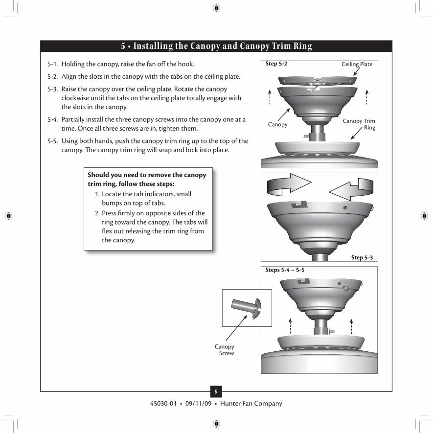
5-1. Holding the canopy, raise the fan off the hook.
5-2. Align the slots in the canopy with the tabs on the ceiling plate.
5-3. Raise the canopy over the ceiling plate. Rotate the canopy clockwise until the tabs on the ceiling plate totally engage with the slots in the canopy.
5-4. Partially install the three canopy screws into the canopy one at a time. Once all three screws are in, tighten them.
5-5. Using both hands, push the canopy trim ring up to the top of the canopy. The canopy trim ring will snap and lock into place.
Should you need to remove the canopy trim ring, follow these steps: 1. Locate the tab indicators, small
bumps on top of tabs. 2. Press firmly on opposite sides of the
ring toward the canopy. The tabs will flex out releasing the trim ring from the canopy.
Step 5-2
Canopy Trim RingCanopy
Ceiling Plate
Step 5-3
Steps 5-4 – 5-5
Canopy Screw
5 • Installing the Canopy and Canopy Trim Ring

9
45030-01 • 09/11/09 • Hunter Fan Company
Hunter fans use several styles of fan blade irons (brackets that hold the blade to the fan).
6-1. Your fan may include blade grommets. If your fan has grommets, insert them by hand into the holes on the blades.
6-2. Attach each blade to a blade iron using three blade assembly screws. If you used grommets, the blades may appear slightly loose after screws are tightened. This is normal.
6-3. Remove the blade mounting screws and rubber shipping bumpers from the motor. Note: Some blade mounting screws are installed in the motor to secure shipping blocks.
6-4. For each blade, insert one blade mounting screw through the blade iron, and attach lightly to the fan. Insert the second blade mounting screw, then securely tighten both mounting screws.
Step 6-1 (Detail)
Blade Assembly ScrewsUse with grommet
Use without grommet
Grommet
Blade Mounting
Screw
Steps 6-1 – 6-2
Step 6-4
6 • Assembling the Blades
10
45030-01 • 09/11/09 • Hunter Fan Company
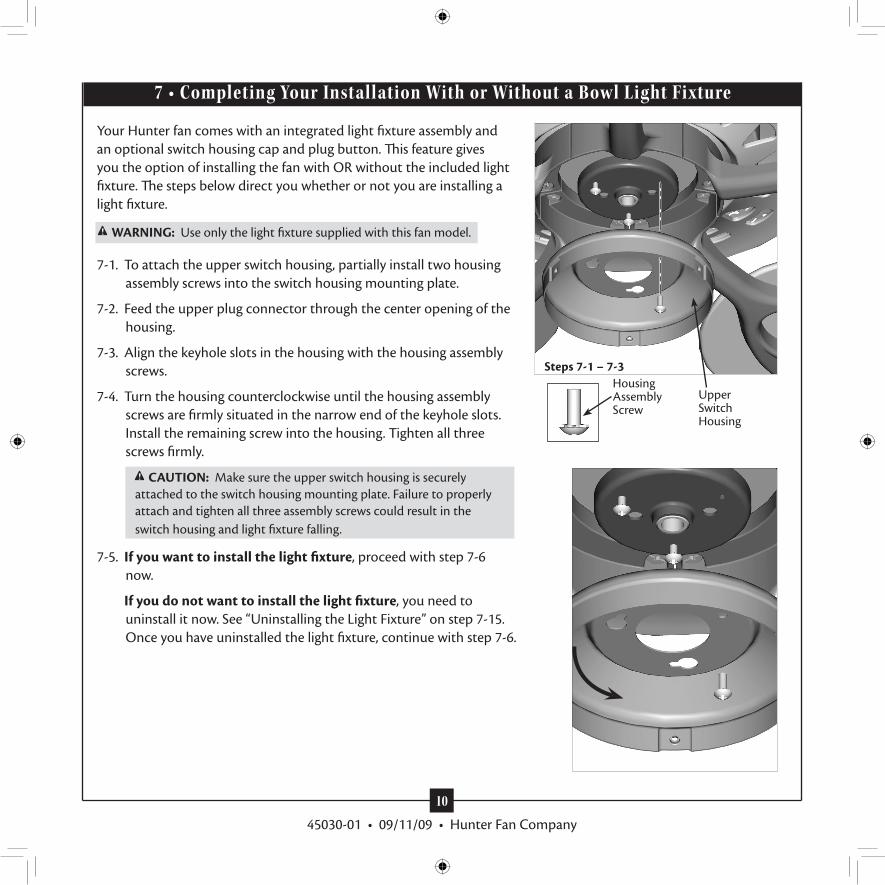
Your Hunter fan comes with an integrated light fixture assembly and an optional switch housing cap and plug button. This feature gives you the option of installing the fan with OR without the included light fixture. The steps below direct you whether or not you are installing a light fixture.
WARNING: Use only the light fixture supplied with this fan model.
7-1. To attach the upper switch housing, partially install two housing assembly screws into the switch housing mounting plate.
7-2. Feed the upper plug connector through the center opening of the housing.
7-3. Align the keyhole slots in the housing with the housing assembly screws.
7-4. Turn the housing counterclockwise until the housing assembly screws are firmly situated in the narrow end of the keyhole slots. Install the remaining screw into the housing. Tighten all three screws firmly.
CAUTION: Make sure the upper switch housing is securely attached to the switch housing mounting plate. Failure to properly attach and tighten all three assembly screws could result in the switch housing and light fixture falling.
7-5 . If you want to install the light fixture, proceed with step 7-6 now.
If you do not want to install the light fixture, you need to uninstall it now. See “Uninstalling the Light Fixture” on step 7-15. Once you have uninstalled the light fixture, continue with step 7-6.
Steps 7-1 – 7-3Housing Assembly Screw
Upper Switch Housing
7 • Completing Your Installation With or Without a Bowl Light Fixture
11
45030-01 • 09/11/09 • Hunter Fan Company
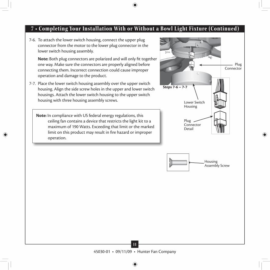
Lower Switch Housing
Plug Connector
Housing Assembly Screw
Plug Connector Detail
Steps 7-6 – 7-7
7-6. To attach the lower switch housing, connect the upper plug connector from the motor to the lower plug connector in the lower switch housing assembly.
Note: Both plug connectors are polarized and will only fit together one way. Make sure the connectors are properly aligned before connecting them. Incorrect connection could cause improper operation and damage to the product.
7-7. Place the lower switch housing assembly over the upper switch housing. Align the side screw holes in the upper and lower switch housings. Attach the lower switch housing to the upper switch housing with three housing assembly screws.
Note: In compliance with US federal energy regulations, this ceiling fan contains a device that restricts the light kit to a maximum of 190 Watts. Exceeding that limit or the marked limit on this product may result in fire hazard or improper operation.
7 • Completing Your Installation With or Without a Bowl Light Fixture (Continued)
12
45030-01 • 09/11/09 • Hunter Fan Company
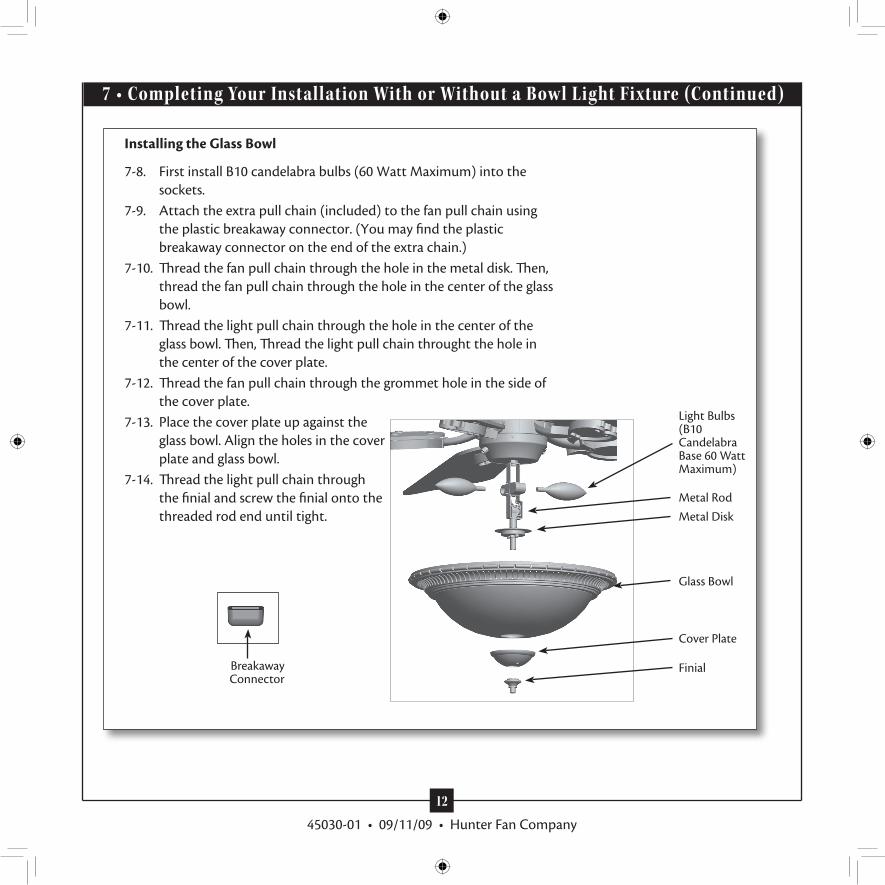
Installing the Glass Bowl
7-8. First install B10 candelabra bulbs (60 Watt Maximum) into the sockets.
7-9. Attach the extra pull chain (included) to the fan pull chain using the plastic breakaway connector. (You may find the plastic breakaway connector on the end of the extra chain.)
7-10. Thread the fan pull chain through the hole in the metal disk. Then, thread the fan pull chain through the hole in the center of the glass bowl.
7-11. Thread the light pull chain through the hole in the center of the glass bowl. Then, Thread the light pull chain throught the hole in the center of the cover plate.
7-12. Thread the fan pull chain through the grommet hole in the side of the cover plate.
7-13. Place the cover plate up against the glass bowl. Align the holes in the cover plate and glass bowl.
7-14. Thread the light pull chain through the finial and screw the finial onto the threaded rod end until tight.
Breakaway Connector
Light Bulbs (B10 Candelabra Base 60 Watt Maximum)
Metal RodMetal Disk
Glass Bowl
Cover Plate
Finial
7 • Completing Your Installation With or Without a Bowl Light Fixture (Continued)

13
45030-01 • 09/11/09 • Hunter Fan Company
Uninstalling the Light Fixture
7-15. To uninstall the light fixture, first disconnect the plug connectors between the black wire and the red wire.
7-16. Disconnect the plug connectors between the two white wires.
7-17. Uninstall the connector and washer from the end of the light fixture inside the lower switch housing.
7-18. Unscrew the threaded rod of the light fixture from the lower switch housing.
7-19. Remove the light fixture from the lower switch housing pulling disconnected wires through the hole in the center of the lower switch housing.
Note: When removing the wires, pull the thin plug connector (male) through first, and then pull the other plug connector (female) through the hole.
7-20. Install the dummy terminals (included in the sack parts) on the two disconnected wires in the lower switch housing.
7-21. Install the switch housing cap and plug button to the lower switch housing.
7-22. Once you have uninstalled the light fixture, continue with step 7-6.
Lower Switch Housing
Threaded Rod
Steps 7-17 – 7-19
Male Dummy Terminal
Female Dummy Terminal
Step 7-21
Cap
Plug Button
7 • Completing Your Installation With or Without a Bowl Light Fixture (Continued)
14
45030-01 • 09/11/09 • Hunter Fan Company
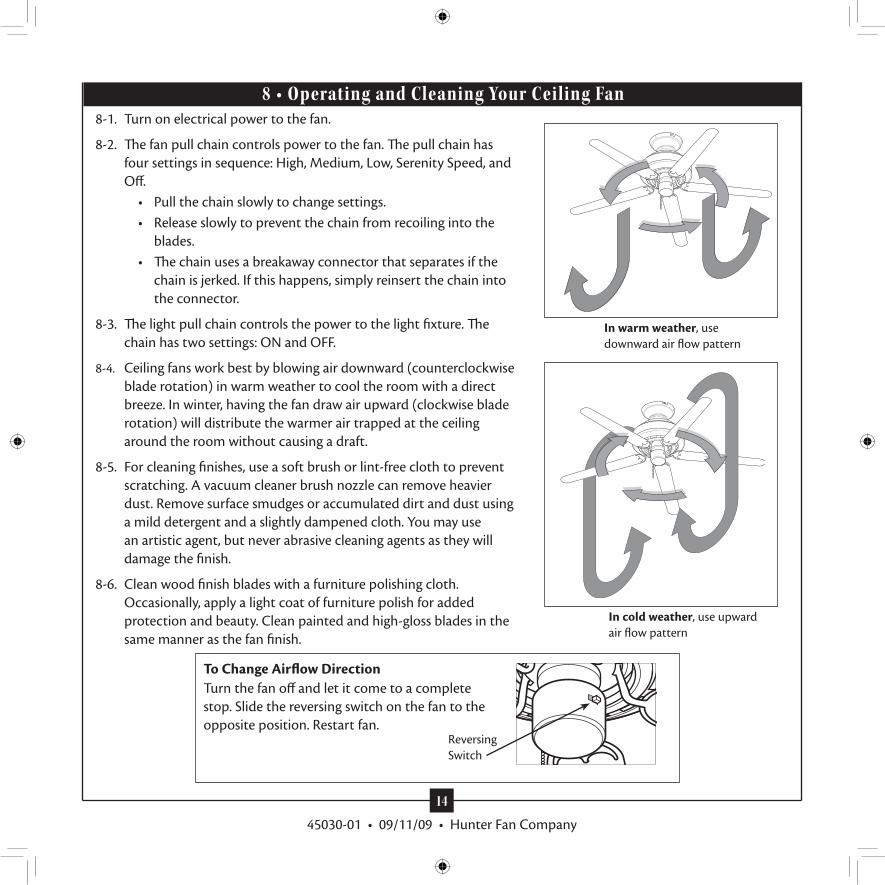
In warm weather, use downward air flow pattern
In cold weather, use upward air flow pattern
8-1. Turn on electrical power to the fan.
8-2. The fan pull chain controls power to the fan. The pull chain has four settings in sequence: High, Medium, Low, Serenity Speed, and Off.
• Pull the chain slowly to change settings.• Release slowly to prevent the chain from recoiling into the
blades.• The chain uses a breakaway connector that separates if the
chain is jerked. If this happens, simply reinsert the chain into the connector.
8-3. The light pull chain controls the power to the light fixture. The chain has two settings: ON and OFF.
8-4 . Ceiling fans work best by blowing air downward (counterclockwise blade rotation) in warm weather to cool the room with a direct breeze. In winter, having the fan draw air upward (clockwise blade rotation) will distribute the warmer air trapped at the ceiling around the room without causing a draft.
8-5. For cleaning finishes, use a soft brush or lint-free cloth to prevent scratching. A vacuum cleaner brush nozzle can remove heavier dust. Remove surface smudges or accumulated dirt and dust using a mild detergent and a slightly dampened cloth. You may use an artistic agent, but never abrasive cleaning agents as they will damage the finish.
8-6. Clean wood finish blades with a furniture polishing cloth. Occasionally, apply a light coat of furniture polish for added protection and beauty. Clean painted and high-gloss blades in the same manner as the fan finish.
To Change Airflow DirectionTurn the fan off and let it come to a complete stop. Slide the reversing switch on the fan to the opposite position. Restart fan.
Reversing Switch
8 • Operating and Cleaning Your Ceiling Fan
15
45030-01 • 09/11/09 • Hunter Fan Company
Problem: Nothing happens; fan does not move.1. Turn power on, replace fuse, or reset breaker.2. Loosen canopy, check all connections according to the wiring the
fan section.3. Check the plug connection in the switch housing.4. Push motor reversing switch firmly left or right to ensure that the
switch is engaged.5. Pull the pull chain to ensure it is on.6. Remove the shipping bumpers.
Problem: Noisy operation.1. Tighten the blade assembly screws and blade iron armature screws
until snug.2. Check to see if the blade is cracked. If so, replace all the blades.
Problem: Excessive wobbling.1. If your fan wobbles when operating, use the enclosed balancing kit
and instructions to balance the fan.2. Tighten all blade iron screws.3. Turn power off, support fan very carefully, and check that the
hanger ball is properly seated.Problem: Lights dim when turned on or do not turn on
1. Check to make sure wattage of light bulbs installed match the specifications on the light socket.
Problem: If the light on this fan shuts off suddenly.1. Turn the power to the fan off at the wall switch. Wait 30 seconds, then resume power to the fan.
If you need parts or service assistance, please call 888-830-1326 (In Canada, call 1-866-268-1936) or visit us at our Web site at http://www.hunterfan.com.
Hunter Fan Company7130 Goodlett Farms Pkwy. #400Memphis, Tennessee 38016
9 • Troubleshooting