Embed Size (px)
Citation preview
Injection valve,type TXI 2
Technical leafletREFRIGERATION AND AIR CONDITIONING
2 DKRCC.PD.AV0.A2.02 / 520H0699 © Danfoss A/S (RC-CMS / AD), 08 - 2005
Technical leaflet Injection valve, type TXI 2
Introduction
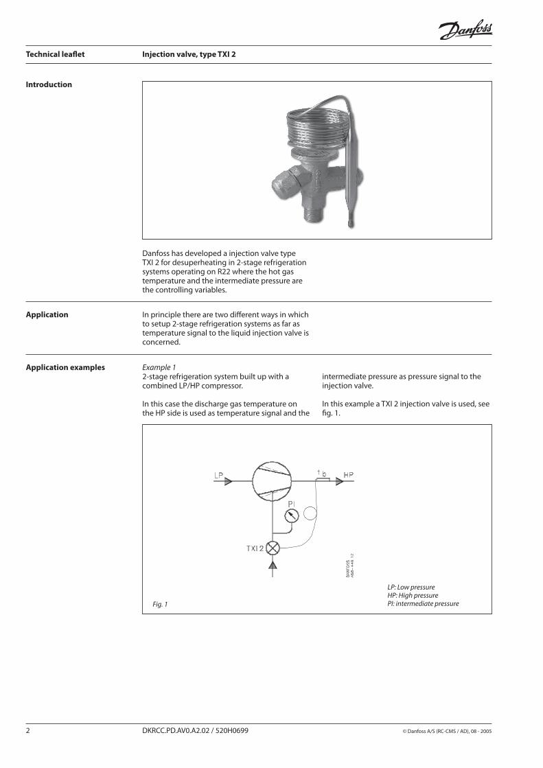
Danfoss has developed a injection valve type TXI 2 for desuperheating in 2-stage refrigeration systems operating on R22 where the hot gas temperature and the intermediate pressure are the controlling variables.
Application In principle there are two different ways in which to setup 2-stage refrigeration systems as far as temperature signal to the liquid injection valve is concerned.
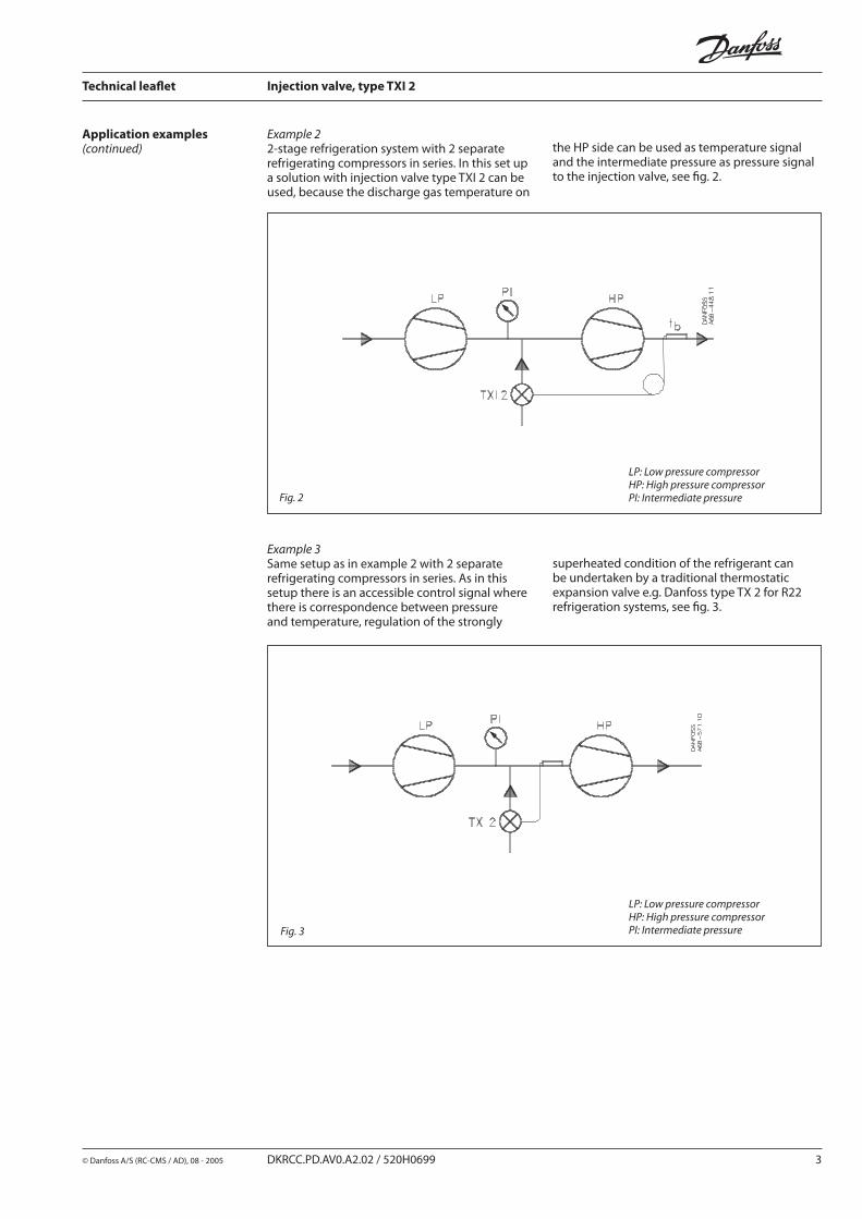
Example 12-stage refrigeration system built up with a combined LP/HP compressor.
In this case the discharge gas temperature on the HP side is used as temperature signal and the
Fig. 1
LP: Low pressureHP: High pressurePI: intermediate pressure
intermediate pressure as pressure signal to the injection valve.
In this example a TXI 2 injection valve is used, see fig. 1.
Application examples
© Danfoss A/S (RC-CMS / AD), 08 - 2005 DKRCC.PD.AV0.A2.02 / 520H0699 3
Technical leaflet Injection valve, type TXI 2
Example 22-stage refrigeration system with 2 separate refrigerating compressors in series. In this set up a solution with injection valve type TXI 2 can be used, because the discharge gas temperature on
Fig. 2
LP: Low pressure compressorHP: High pressure compressorPI: Intermediate pressure
the HP side can be used as temperature signal and the intermediate pressure as pressure signal to the injection valve, see fig. 2.
Application examples(continued)
Example 3Same setup as in example 2 with 2 separate refrigerating compressors in series. As in this setup there is an accessible control signal where there is correspondence between pressure and temperature, regulation of the strongly
LP: Low pressure compressorHP: High pressure compressorPI: Intermediate pressureFig. 3
superheated condition of the refrigerant can be undertaken by a traditional thermostatic expansion valve e.g. Danfoss type TX 2 for R22 refrigeration systems, see fig. 3.
4 DKRCC.PD.AV0.A2.02 / 520H0699 © Danfoss A/S (RC-CMS / AD), 08 - 2005
Technical leaflet Injection valve, type TXI 2
Operation
Fig. 4
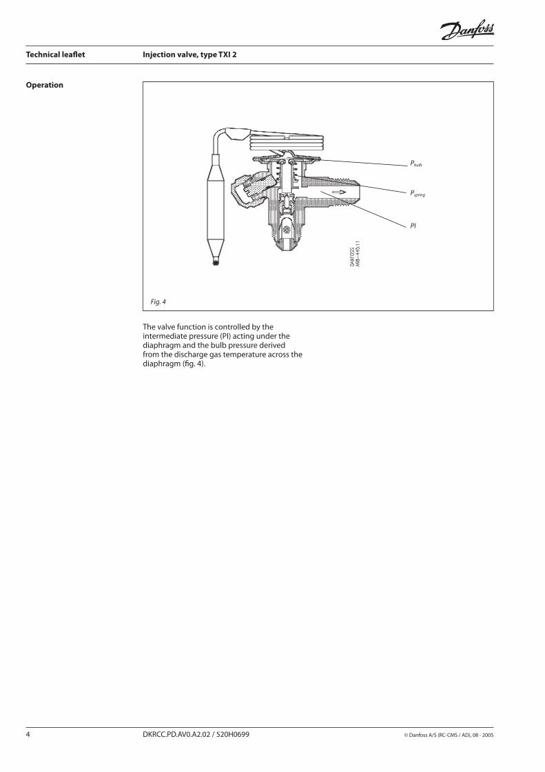
The valve function is controlled by the intermediate pressure (PI) acting under the diaphragm and the bulb pressure derived from the discharge gas temperature across the diaphragm (fig. 4).
PI
Pbulb
Pspring
© Danfoss A/S (RC-CMS / AD), 08 - 2005 DKRCC.PD.AV0.A2.02 / 520H0699 5
Technical leaflet Injection valve, type TXI 2
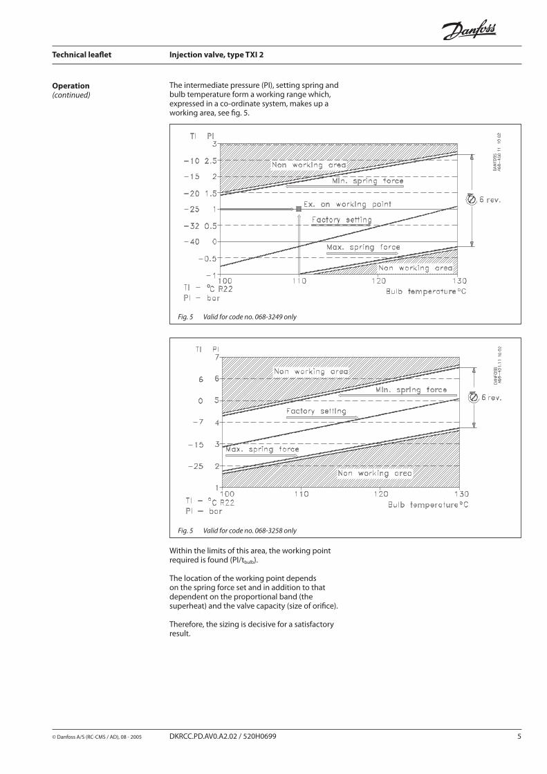
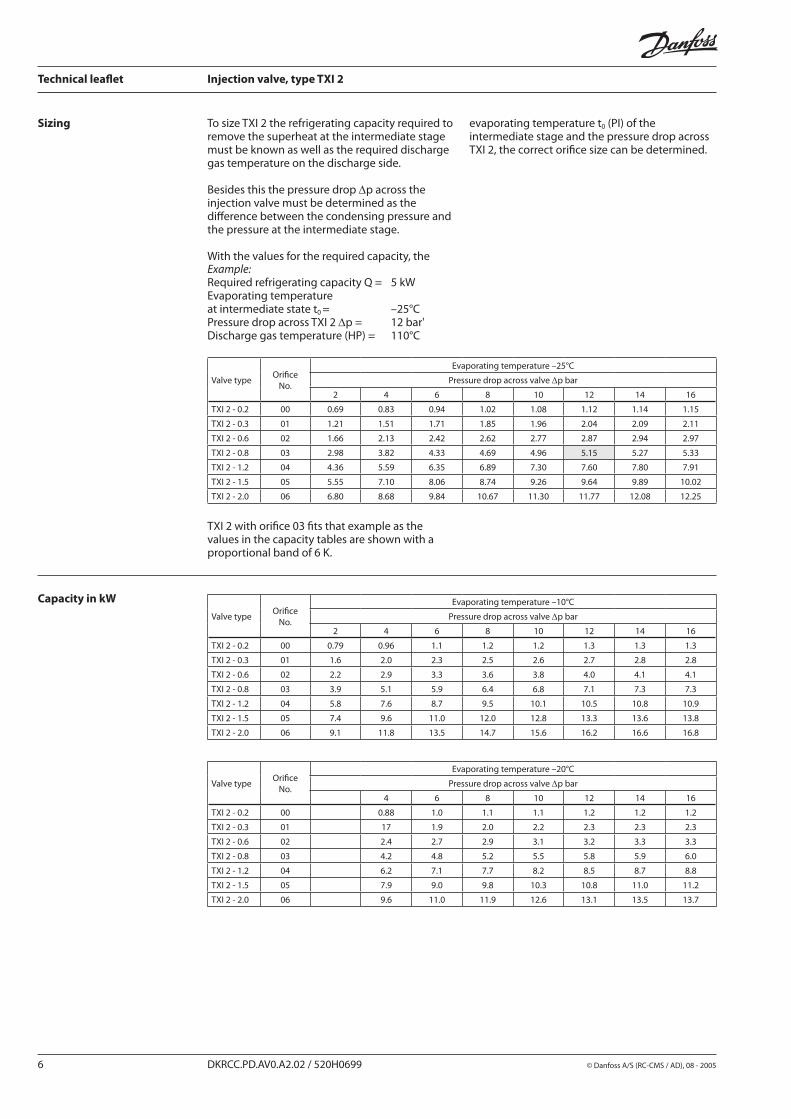
The intermediate pressure (PI), setting spring and bulb temperature form a working range which, expressed in a co-ordinate system, makes up a working area, see fig. 5.
Within the limits of this area, the working point required is found (PI/tbulb).
The location of the working point depends on the spring force set and in addition to that dependent on the proportional band (the superheat) and the valve capacity (size of orifice).
Therefore, the sizing is decisive for a satisfactory result.
Fig. 5 Valid for code no. 068-3249 only
Fig. 5 Valid for code no. 068-3258 only
Operation(continued)
6 DKRCC.PD.AV0.A2.02 / 520H0699 © Danfoss A/S (RC-CMS / AD), 08 - 2005
Technical leaflet Injection valve, type TXI 2
Sizing
Example:Required refrigerating capacity Q = 5 kWEvaporating temperature at intermediate state t0 = –25°CPressure drop across TXI 2 ∆p = 12 bar'Discharge gas temperature (HP) = 110°C
TXI 2 with orifice 03 fits that example as the values in the capacity tables are shown with a proportional band of 6 K.
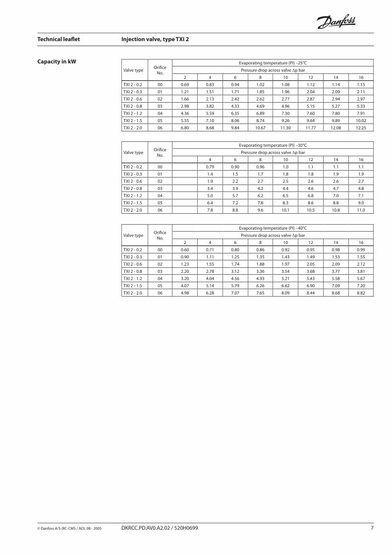
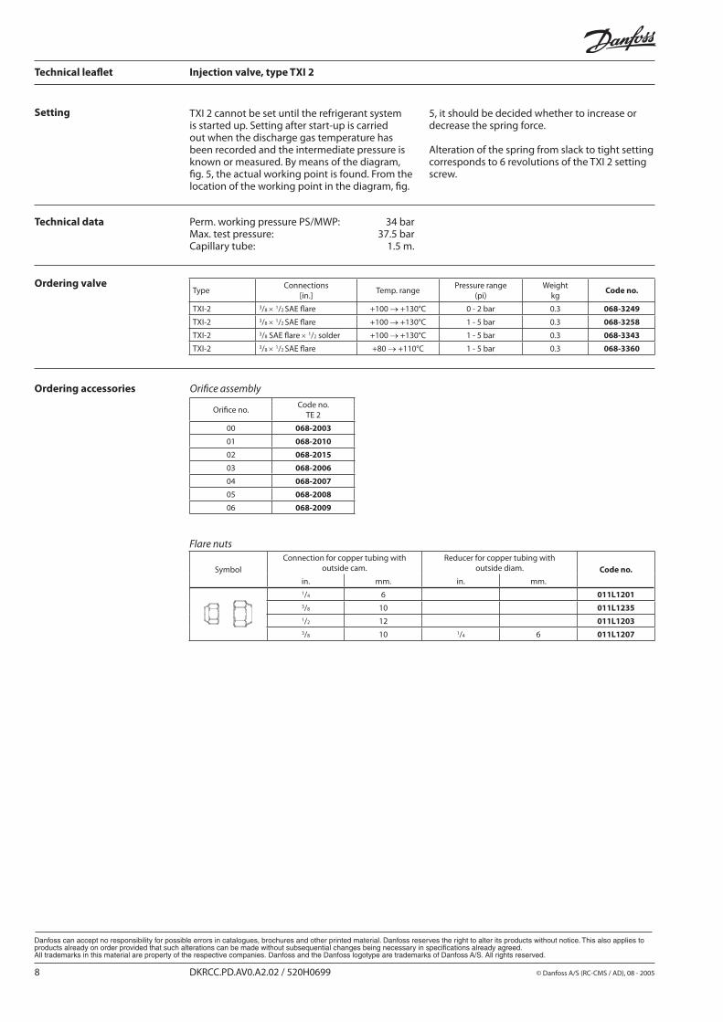
Capacity in kW
To size TXI 2 the refrigerating capacity required to remove the superheat at the intermediate stage must be known as well as the required discharge gas temperature on the discharge side.
Besides this the pressure drop ∆p across the injection valve must be determined as the difference between the condensing pressure and the pressure at the intermediate stage.
With the values for the required capacity, the
evaporating temperature t0 (PI) of theintermediate stage and the pressure drop across TXI 2, the correct orifice size can be determined.
Valve typeOrifice
No.
Evaporating temperature –25°C
Pressure drop across valve ∆p bar
2 4 6 8 10 12 14 16
TXI 2 - 0.2 00 0.69 0.83 0.94 1.02 1.08 1.12 1.14 1.15
TXI 2 - 0.3 01 1.21 1.51 1.71 1.85 1.96 2.04 2.09 2.11
TXI 2 - 0.6 02 1.66 2.13 2.42 2.62 2.77 2.87 2.94 2.97
TXI 2 - 0.8 03 2.98 3.82 4.33 4.69 4.96 5.15 5.27 5.33
TXI 2 - 1.2 04 4.36 5.59 6.35 6.89 7.30 7.60 7.80 7.91
TXI 2 - 1.5 05 5.55 7.10 8.06 8.74 9.26 9.64 9.89 10.02
TXI 2 - 2.0 06 6.80 8.68 9.84 10.67 11.30 11.77 12.08 12.25
Valve typeOrifice
No.
Evaporating temperature –10°C
Pressure drop across valve ∆p bar
2 4 6 8 10 12 14 16
TXI 2 - 0.2 00 0.79 0.96 1.1 1.2 1.2 1.3 1.3 1.3
TXI 2 - 0.3 01 1.6 2.0 2.3 2.5 2.6 2.7 2.8 2.8
TXI 2 - 0.6 02 2.2 2.9 3.3 3.6 3.8 4.0 4.1 4.1
TXI 2 - 0.8 03 3.9 5.1 5.9 6.4 6.8 7.1 7.3 7.3
TXI 2 - 1.2 04 5.8 7.6 8.7 9.5 10.1 10.5 10.8 10.9
TXI 2 - 1.5 05 7.4 9.6 11.0 12.0 12.8 13.3 13.6 13.8
TXI 2 - 2.0 06 9.1 11.8 13.5 14.7 15.6 16.2 16.6 16.8
Valve typeOrifice
No.
Evaporating temperature –20°C
Pressure drop across valve ∆p bar
4 6 8 10 12 14 16
TXI 2 - 0.2 00 0.88 1.0 1.1 1.1 1.2 1.2 1.2
TXI 2 - 0.3 01 17 1.9 2.0 2.2 2.3 2.3 2.3
TXI 2 - 0.6 02 2.4 2.7 2.9 3.1 3.2 3.3 3.3
TXI 2 - 0.8 03 4.2 4.8 5.2 5.5 5.8 5.9 6.0
TXI 2 - 1.2 04 6.2 7.1 7.7 8.2 8.5 8.7 8.8
TXI 2 - 1.5 05 7.9 9.0 9.8 10.3 10.8 11.0 11.2
TXI 2 - 2.0 06 9.6 11.0 11.9 12.6 13.1 13.5 13.7
© Danfoss A/S (RC-CMS / AD), 08 - 2005 DKRCC.PD.AV0.A2.02 / 520H0699 7
Technical leaflet Injection valve, type TXI 2
Valve typeOrifice
No.
Evaporating temperature (PI) –25°C
Pressure drop across valve ∆p bar
2 4 6 8 10 12 14 16
TXI 2 - 0.2 00 0.69 0.83 0.94 1.02 1.08 1.12 1.14 1.15
TXI 2 - 0.3 01 1.21 1.51 1.71 1.85 1.96 2.04 2.09 2.11
TXI 2 - 0.6 02 1.66 2.13 2.42 2.62 2.77 2.87 2.94 2.97
TXI 2 - 0.8 03 2.98 3.82 4.33 4.69 4.96 5.15 5.27 5.33
TXI 2 - 1.2 04 4.36 5.59 6.35 6.89 7.30 7.60 7.80 7.91
TXI 2 - 1.5 05 5.55 7.10 8.06 8.74 9.26 9.64 9.89 10.02
TXI 2 - 2.0 06 6.80 8.68 9.84 10.67 11.30 11.77 12.08 12.25
Valve typeOrifice
No.
Evaporating temperature (PI) –30°C
Pressure drop across valve ∆p bar
4 6 8 10 12 14 16
TXI 2 - 0.2 00 0.79 0.90 0.96 1.0 1.1 1.1 1.1
TXI 2 - 0.3 01 1.4 1.5 1.7 1.8 1.8 1.9 1.9
TXI 2 - 0.6 02 1.9 2.2 2.7 2.5 2.6 2.6 2.7
TXI 2 - 0.8 03 3.4 3.9 4.2 4.4 4.6 4.7 4.8
TXI 2 - 1.2 04 5.0 5.7 6.2 6.5 6.8 7.0 7.1
TXI 2 - 1.5 05 6.4 7.2 7.8 8.3 8.6 8.8 9.0
TXI 2 - 2.0 06 7.8 8.8 9.6 10.1 10.5 10.8 11.0
Valve typeOrifice
No.
Evaporating temperature (PI) –40°C
Pressure drop across valve ∆p bar
2 4 6 8 10 12 14 16
TXI 2 - 0.2 00 0.60 0.71 0.80 0.86 0.92 0.95 0.98 0.99
TXI 2 - 0.3 01 0.90 1.11 1.25 1.35 1.43 1.49 1.53 1.55
TXI 2 - 0.6 02 1.23 1.55 1.74 1.88 1.97 2.05 2.09 2.12
TXI 2 - 0.8 03 2.20 2.78 3.12 3.36 3.54 3.68 3.77 3.81
TXI 2 - 1.2 04 3.20 4.04 4.56 4.93 5.21 5.43 5.58 5.67
TXI 2 - 1.5 05 4.07 5.14 5.79 6.26 6.62 6.90 7.09 7.20
TXI 2 - 2.0 06 4.98 6.28 7.07 7.65 8.09 8.44 8.68 8.82
Capacity in kW
8 DKRCC.PD.AV0.A2.02 / 520H0699 © Danfoss A/S (RC-CMS / AD), 08 - 2005
Technical leaflet Injection valve, type TXI 2
Setting TXI 2 cannot be set until the refrigerant system is started up. Setting after start-up is carried out when the discharge gas temperature has been recorded and the intermediate pressure is known or measured. By means of the diagram, fig. 5, the actual working point is found. From the location of the working point in the diagram, fig.
Technical data Perm. working pressure PS/MWP: 34 barMax. test pressure: 37.5 barCapillary tube: 1.5 m.
Ordering valve
Ordering accessories
5, it should be decided whether to increase or decrease the spring force.
Alteration of the spring from slack to tight setting corresponds to 6 revolutions of the TXI 2 setting screw.
Flare nuts
SymbolConnection for copper tubing with
outside cam.Reducer for copper tubing with
outside diam. Code no.in. mm. in. mm.1/4 6 011L12013/8 10 011L12351/2 12 011L12033/8 10 1/4 6 011L1207
Orifice assembly
Orifice no.Code no.
TE 2
00 068-2003
01 068-2010
02 068-2015
03 068-2006
04 068-2007
05 068-2008
06 068-2009
TypeConnections
[in.]Temp. range
Pressure range(pi)
Weight kg
Code no.
TXI-2 3/8 × 1/2 SAE flare +100 → +130°C 0 - 2 bar 0.3 068-3249
TXI-2 3/8 × 1/2 SAE flare +100 → +130°C 1 - 5 bar 0.3 068-3258
TXI-2 3/8 SAE flare × 1/2 solder +100 → +130°C 1 - 5 bar 0.3 068-3343
TXI-2 3/8 × 1/2 SAE flare +80 → +110°C 1 - 5 bar 0.3 068-3360


