Embed Size (px)
Citation preview

F E A T U R E S
P R O D U C TC O N T R O L & D I S P L A Y
www.trolex.com
1
ISS.D IDS:07/03
T X 2 1 0 0
of 13
I/O command and control system for:-Sensors • Control Devices • Alarms
••••••••••••••••••• Bus expandable distributed I/O.
••••••••••••••••••• User configurable input signals and output drivers.
••••••••••••••••• Programmable sensor response functions.
••••••••••••••••• Programmable control functions.
••••••••••••••••• Data logging.
••••••••••••••••• Datacomms for distributed systems.
••••••••••••••••• Intrinsically safe for hazardous area operation.
••••••••••••••••• Galvanically isolated I/O and databus.
COMMANDER
Commandbus
SENSOR INPUTS
CONTROL OUTPUTS
SENSOR INPUTS
CONTROL OUTPUTS

P R O D U C TC O N T R O L & D I S P L A Y
2
ISS.D IDS:07/03
T X 2 1 0 0
of 13
TX2101 COMMAND MODULE
The command centre of the system with digitaldisplay, navigator programming keypad, andcommandbus connector.
••••••••••••••••• Sensor Input/Output Status DisplayIndividual display for each I/O channel with signal bar-graph text entry for sensor duty and alarm setpoint data.
••••••••••••••••• Direct Input Set-upEasy-to-use, icon led set-up routine, direct programmingthrough the navigator keypad. Infinitely flexible alarmfunction programming.
••••••••••••••••• Data HistoryData retention of minimum and maximum signal values with graphical trending.
Data logging of sensor data and output events with time, date and identification.
••••••••••••••••• Sensor Signal Function ProgrammingCharacterisation of sensor response including;
Rising/falling signal, Hysteresis, Scaling, Engineering units,
Offset, Damping, Sample Rate and Fault monitoring.
Programmable Control FunctionsDirect programming of basic control functions and alarmgrouping.
Custom software modules can be incorporated for sequentialcontrol, time delays, algebraic functions, logic functions,mathematical functions, counting, rate-of-rise, algorithms,comparitors, etc.
CommandbusExtendible I/O communication buswith power supply distribution toeach channel.
DatacommsRS485 based datacomms for distributedmonitoring and control systems.
MODBUS • SAP • ETHERNET
P R O D U C TC O N T R O L & D I S P L A Y
3
ISS.D IDS:07/03
T X 2 1 0 0
of 13
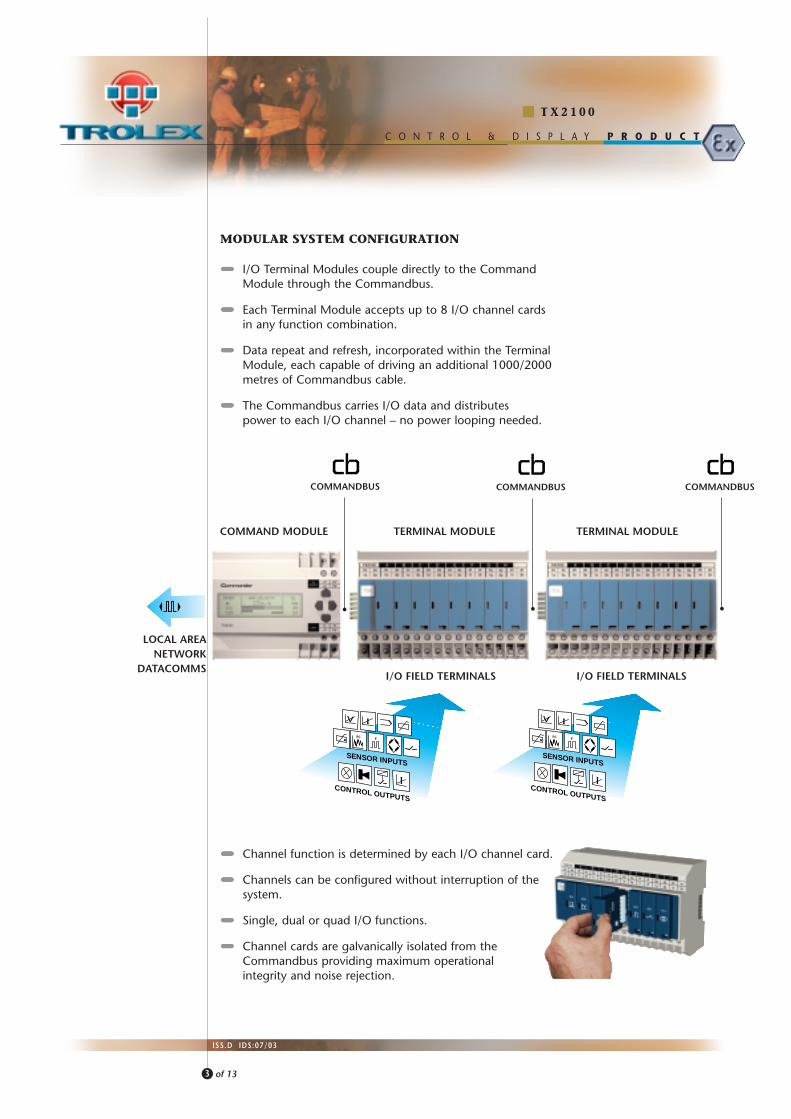
MODULAR SYSTEM CONFIGURATION
••••••••••••••••••• I/O Terminal Modules couple directly to the Command Module through the Commandbus.
••••••••••••••••••• Each Terminal Module accepts up to 8 I/O channel cardsin any function combination.
••••••••••••••••••• Data repeat and refresh, incorporated within the Terminal Module, each capable of driving an additional 1000/2000 metres of Commandbus cable.
••••••••••••••••••• The Commandbus carries I/O data and distributes power to each I/O channel – no power looping needed.
SENSOR INPUTS
CONTROL OUTPUTS
SENSOR INPUTS
CONTROL OUTPUTS
COMMAND MODULE TERMINAL MODULE TERMINAL MODULE
I/O FIELD TERMINALS I/O FIELD TERMINALS
COMMANDBUS COMMANDBUS
LOCAL AREANETWORK
DATACOMMS
••••••••••••••••••• Channel function is determined by each I/O channel card.
••••••••••••••••••• Channels can be configured without interruption of the system.
••••••••••••••••••• Single, dual or quad I/O functions.
••••••••••••••••••• Channel cards are galvanically isolated from the Commandbus providing maximum operationalintegrity and noise rejection.
COMMANDBUS

I / O C H A N N E LC A R D S
4
ISS.D IDS:07/03
T X 2 1 0 0
of 13
P R O D U C TC O N T R O L & D I S P L A Y
ANALOGUE INPUT CHANNEL CARDS
TX2141.301.03 4...20mA Input..01.02
TX2141.302.03 Dual 4...20mA Input..01.02
TX2141.303.03 0.4...2V Input..01.02
TX2141.304.03 Dual 0.4...2V Input..01.02
TX2141.306.03 PT100 Temp. Input .01.02
• Measuring Range: –50°C...200°C • –50°C...400°C
TX2141.307.03 Dual PT100 Temp. Input..01.02
• Measuring Range: –50°C...200°C • –50°C...400°C
TX2141.308.03 Dual S/C Temp. Input. .01.02
• Measuring Range: 0°C...100°C • 0°C...200°C
TX2141.309.03 ac & Vibration Input.01.02
• Bandpass Frequency: 10Hz...100hz • 500Hz...10kHz
TX2141.310.03 mV Input..01.02
• Measuring Range: 0...2mV • 0...5mV • 0...10mV •0...50mV • 0...100mV • 0...1V • 0...2V •Specific Measuring Range
ONOFF/STATE OUTPUT CHANNEL CARDS
TX2141.601.01 Reed Relay Output..02
(Clearance compliant for intrinsically safe circuits).
TX2141.603.03 Quad Solid State Output.TX2141.603.01
TX2141.604.03 Dual Relay Output.
PULSE FREQUENCY INPUT CHANNEL CARDS
TX2141.401.03 Pulse/frequency Input..01.02
Counting, frequency measurement. Speed sensing, pulsecomparison.
ONOFF/STATE INPUT CHANNEL CARDS
TX2141.501.03 Dual NAMUR Input..01.02
TX2141.502.03 Dual ONOFF Input..01.02
(with line monitoring diode)
TX2141.503.03 Dual Current Loop .01 State Input..02
TX2141.504.03 Quad ONOFF Input.TX2141.504.01
ANALOGUE OUTPUT CHANNEL CARD
TX2141.701.03 Dual 4...20mA Output..01.02
Suffix .03: GENERAL PURPOSE
(eg. TX2141.301.03)
Suffix .01: GROUP I
(eg. TX2141.301.01)
Suffix .02: GROUP II
(eg. TX2141.301.02)
AREA CLASSIFICATION
5
ISS.D IDS:07/03
T X 2 1 0 0
of 13
P R O D U C TC O N T R O L & D I S P L A Y
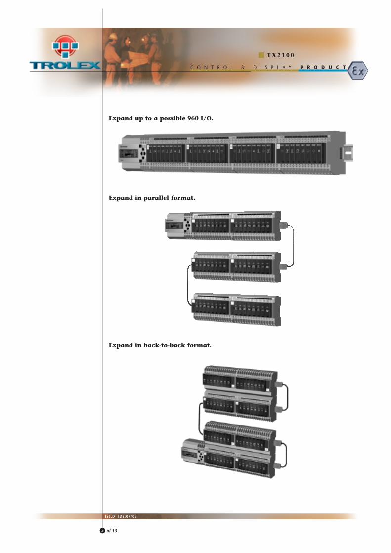
Expand up to a possible 960 I/O.
Expand in back-to-back format.
Expand in parallel format.

6
ISS.D IDS:07/03
of 13
P R O D U C TC O N T R O L & D I S P L A Y
T X 2 1 0 0
••••••••••••••••••• Install the Command module at a convenient dispersed location.
••••••••••••••••••• Plant cables terminated directlyto the I/O Terminal Modules.
••••••••••••••••••• Panel wiring eliminated.
••••••••••••••••••• Fit a Commandbus convertor module for cable runs to remoteI/O Terminal Modules.
••••••••••••••••••• Each Terminal Module added to a Commandbus will provide up to2000 metres of additional Commandbus transmission distance.
SENSOR INPUTS
CONTROL OUTPUTS
SENSOR INPUTS
CONTROL OUTPUTS

P R O D U C TC O N T R O L & D I S P L A Y
A P P R O V A L SA N D
C E R T I F I C A T I O N
D I M E N S I O N S
7
ISS.D IDS:07/03
T X 2 1 0 0
of 13
T E C H N I C A Ld e t a i l s
TX2101.03 TX2101.01 TX2101.02General Purpose Group I Group II
Ambient Temp. Limits: –10 °C...50°C
Electrical Connections: 3.5mm barrier/clamp terminals.
Housing Material: Glass filled polycarbonate.
Environmental Protection: IP55 (must be housed in protective metal enclosure).
Information Display: 32 x 122 pixels. Graphic LCD with backlight.
Processor: Microprocessor controlled menu operation with non-volatile data retention.16 bit A/D conversion
Programming: Fourway NAVIGATOR keypad.Sensor input signal function programming.
output control function programming.
Datalog: 2000 readings per channel with Time/Date/Duty. Data listing or graphical trend display.
Datacomms: LAN 1 and LAN 2 RS485 datacomms output for multipoint distributed systems.
Supply Voltage: 24V dc 12V dc 24V dc(From approved (From TX2172
Intrinsically Safe Source) Power Supply ONLY)
Isolation: All input and output circuits are galvanically isolated from the Commandbus.All power supplies to TX2102 terminal Modules are galvanically isolated.
All Commandbus data is galvanically isolated at all exit ports.
TØ1
3658
99 90
90 C
TRS
105
TX2101TX2131 TX2102
AlternativeFixing Holes
ø4mm
14076
� Certified Intrinsically Safe to Euronorm Standards: EEx iad IIC T4EEx ia I
� Performance approved to Euronorm Standards: EN50054EN50055EN50057
� Designed to comply with: ATEX directiveEMC directive
C O M M A N D E RI N A
G R O U P I IH A Z A R D O U S
A R E A U S I N GA T X 2 1 7 2
E x e P O W E RS U P P L Y
C O M M A N D E RI N A
G R O U P IH A Z A R D O U S
A R E A
8
ISS.D IDS:07/03
T X 2 1 0 0
of 13
P R O D U C TC O N T R O L & D I S P L A Y
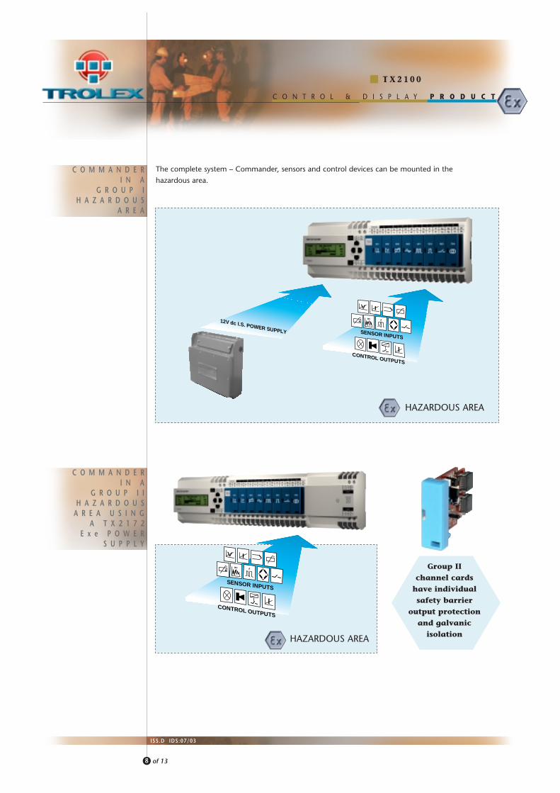
12V dc I.S. POWER SUPPLY
The complete system – Commander, sensors and control devices can be mounted in the
hazardous area.
SENSOR INPUTS
CONTROL OUTPUTS
SENSOR INPUTS
CONTROL OUTPUTS
Group IIchannel cards
have individualsafety barrier
output protectionand galvanic
isolation
HAZARDOUS AREA
HAZARDOUS AREA

D A T A C O M M SF O R
D I S T R I B U T E DC O M M A N D E R
S Y S T E M S
9
ISS.D IDS:07/03
T X 2 1 0 0
of 13
P R O D U C TC O N T R O L & D I S P L A Y
The Command module has two alternative output ports each providingRS485 datacomms, one in Connector format the other in Terminal format.
Commander communicating DIRECTLY with an Operator Interface or aPC based network using the RS485 datacomms output.
RS485DATACOMMS
RS485DATACOMMS
RS485DATACOMMS
••••••••••••••••••• MODBUS••••••••••••••••••• SAP••••••••••••••••••• ETHERNET
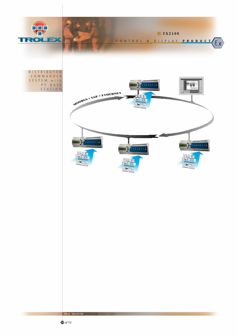
D I S T R I B U T E DC O M M A N D E R
S Y S T E M w i t hP C B A S ES T A T I O N
P R O D U C TC O N T R O L & D I S P L A Y
10
ISS.D IDS:07/03
T X 2 1 0 0
of 13
SENSOR INPUTS
CONTROL OUTPUTS
SENSOR INPUTS
CONTROL OUTPUTS
SENSOR INPUTS
CONTROL OUTPUTS
SENSOR INPUTS
CONTROL OUTPUTS

P R O D U C TC O N T R O L & D I S P L A Y
O R D E RR E F E R E N C E
11
ISS.D IDS:07/03
T X 2 1 0 0
of 13
COMMAND MODULE. DIN. General Purpose.
COMMAND MODULE. DIN. Group I.
COMMAND MODULE. DIN. Group II.
T X 2 1 0 1 . 0 3
T X 2 1 0 1 . 0 1
T X 2 1 0 1 . 0 2
COMMAND MODULE. PANEL. General Purpose.
COMMAND MODULE. PANEL. Group I.
COMMAND MODULE. PANEL. Group II.
T X 2 1 0 4 . 0 3
T X 2 1 0 4 . 0 1
T X 2 1 0 4 . 0 2
I/O TERMINAL MODULE. DIN. General Purpose.
I/O TERMINAL MODULE. DIN. Group I.
I/O TERMINAL MODULE. DIN. Group II.
T X 2 1 0 2 . 0 3
T X 2 1 0 2 . 0 1
T X 2 1 0 2 . 0 2
COMMANDBUS CONVERTOR MODULE
Converts the normal Commandbus plug and socket connector, toscrew terminal connections for remote Commandbus cabling.
T X 2 1 3 1
POWER SUPPLY MODULE. General Purpose.
General purpose 24V dc power supply for DIN rail mountingdirectly into the Commandbus.
Please specify: • Supply: 85V ac...264V ac universal• Output: 24V dc• Current: 1A
T X 2 1 7 1
POWER SUPPLY MODULE. Group II.
Special voltage restricted power supply for DIN rail mountingdirectly into the Commandbus.
24V dc for Group II Ex applications.
Please specify: • Supply.110V ac• Supply. 230V ac
T X 2 1 7 2
COMMANDBUS REPEATER MODULE. General Purpose.
COMMANDBUS REPEATER MODULE. Group I.
COMMANDBUS REPEATER MODULE. Group II.
Increase the transmission distance on the Commandbus.
T X 2 1 2 1 . 0 3
T X 2 1 2 1 . 0 1
T X 2 1 2 1 . 0 2
COMMS REPEATER MODULE. Group I.
Increase the transmission distance on the RS485 LAN dataoutput ports.Can also be used as an Intrinsically Safe isolation barrier at thesurface/hazardous area interface.
T X 2 1 2 2 . 0 1
COMMANDER AUTO SETUP SOFTWARE PACKAGE
SETUP the complete Commander programme in software on a PC
and load directly into the Command Module through the LAN 2
data port. Package includes CD and LAN 2 interconnecting cable.
T X 2 1 9 9

H O U S I N G SF O R T H E
C O M M A N D E RS Y S T E M
12
ISS.D IDS:07/03
T X 2 1 0 0
of 13
P R O D U C TC O N T R O L & D I S P L A Y
TX9200 SERIES STAINLESS STEEL COMMANDER HOUSINGS.
• Robust welded stainless steel construction.
• Mounting rails fitted.
• Observation window.
• Hinged cover with lockable fastening.
• Wall fixing facilities.
• IP65 environmental protection.
MOULDED POLYCARBONATE WEATHERPROOF
HOUSINGS IN A RANGE OF SIZES.
• Transparent waterproof hinged covers.
• Wall fixing kit.
• Mounting rails fitted.
• Masking plates provided.
• Choice of cable entry facilities.
300.
0
100.0
Entry holes Ø22.0for M20 cable glands
TX9204TX9202
400.020.0
20.0
200.0
Stand-aloneWall Mounting
Command Module.Terminal Module
with CommandbusConvertor
Compilation Commander Station• Command Module• Comms Repeater• Terminal Module• Commandbus Convertor

P R O D U C TC O N T R O L & D I S P L A Y
A C C E S S O R I E S
TROLEX LIMITED
Newby Road
Haze l Grove, Stockport ,
Chesh i re SK7 5DY, UK.
+44 (0)161-483 1435
+44 (0)161-483 5556
sa les@tro lex .com
www.tro lex .com
t e l :
f a x :
e - m a i l :
i n t e r n e t :
13
ISS.D IDS:07/03
T X 2 1 0 0
of 13
BLANK CHANNEL CARDTo cover unused channel card locations.
T X 2 1 4 1 . 0 8
MARKING TAG BARSelf-adhesive fixing to the TX2102 Terminal Module.Supplied complete with 8 white tags for marking theduty reference of each channel.
T X 2 1 4 1 . 0 9
COMMANDBUS CABLE HEADER. FemaleT X 2 1 5 2
COMMANDBUS CABLE HEADER. MaleT X 2 1 5 3
6 CORE COMMANDBUS CABLE (5 USED). per metre(For use with TX2152 and TX2153)
T X 2 1 5 4
END CLAMP.T X 2 1 5 8
END CLAMP WITH CABLE ANCHOR.Commandbus cable headers can be secured in position byusing the clip provided on this end clamp.
T X 2 1 5 9
COMMANDBUS CABLE HEADER. Male(Internal screw terminal connections).The housing of the connector is fitted with two retainingscrews for anchoring to the TX2104 Series CommandModules, panel mounting version.
T X 2 1 5 1


![ALARM RATIONALIZATIO N: PRACTICAL EXPERIE NCE · Java, based upon the Control System Studio (CSS) platform [4]. I t handles the SNS alarms by providing tools to annunciate alarms](https://img.pdfslide.us/doc/110x75/5f955f8f18f8c143cf47bcb3/alarm-rationalizatio-n-practical-experie-nce-java-based-upon-the-control-system.jpg)


![Car Alarms & Smoke Alarms [Monitorama]](https://img.pdfslide.us/doc/110x75/54b6cdf94a7959d84d8b45a5/car-alarms-smoke-alarms-monitorama.jpg)