Embed Size (px)
Citation preview
FOCUS AREA
TWRS Technology
•iMM*z%& This guide was prepared in corisultation;with~ a number of ;
individuals and organizations bomjnsideand outside of the "'.- -Hanford community. Thegradousg^.l^ffiejfr&eVinsight,''
This guide was designedly'Itose-^^tt^f^e.Pacific r;4';l f: Northwest Laboratory, with art b 'y^oemf^cjmp^r Services '4?rj -, Richland artist Rick Mulr)1^ritten^^^^ 1; by Robert Allen, Kathy BlancKard,^Der^^0iTOffi^"Is&fe-fC<M.. .: Manke, Michaela Mann^^tfra M c ^ ^ O'Connor, Shannon b^b^p^^ana^S^e^d^oJ^elFacHb ,'1Vv',. q Northwest Laboratory.."Furi<Shgfor &e^M»^va^prpyided by ;̂'; . the Tank Waste RemediatirarSystem(B^ ^ Area programs. TnePadncNormwestlaborafbrvjs.operated .?,.. .. for die U.S. Department 6£^ergyiBy"BartelleMemoriaUtastitute * '
'.. under D j n t r a r t . D E ^ 6 ^ X ^ 0 ^ ^ ^ ^ ^ ^ ^ ^ ^ ^ In writing this guide me^u&Vf^foul&'seyeral sources of ; ;,"."
tank waste information-TSomfiiruormatiorcK^ ' ' waste sample analyses and-taiikdesignaaecoi^otKermforma--„-v '• non is an extrapolation fromxeprocessmg(recoras/tchenucal,.j^ w/v -3 purchases, computer moaemgplus^ep^rTOn^knpwIedge >^ - ^ of Hanford staff. Assumptic^:anct.fa^weieJs^meumes found , •-• intermingled. FortrusT£ason;specificTH^^ ••
• especially those usedtci desCTBe^e^eMcalS^racHdac^ve lX: \ nature of the tank waste;>^$ffer^ ras"|>^^ „; ing and mamtairuhgan'Mcmia^^ .-"-date, tank database is^orrecl^erigef^^
DISCLAIMER
This report was prepared as an account of work sponsored by an agency of the United States Government Neither the United States Government nor any agency thereof, nor any of their employees, makes any warranty, express or implied, or assumes any legal liability or responsibility for the accuracy, completeness, or usefulness of any information, apparatus, product, or process disclosed, or represents that its use would not infringe privately owned rights. Reference herein to any specific commercial product, process, or service by trade name, trademark, manufacturer, or otherwise does not necessarily constitute or imply its endorsement, recommendation, or favoring by the United States Government or any agency thereof. The views and opinions of authors expressed herein do not necessarily state or reflect those of the United States Government or any agency thereof.
DISCLAIMER
Portions of this document may be illegible in electronic image products. Images are produced from the best available original document.
PNL-10773
Hanf ord Tank Clean up: A Guide to Understanding the Technical Issues
R.E. Gephart R.E. Lundgren
DISCLAIMER
This report was prepared as an account of work sponsored by an agency of the United States Government. Neither the United States Government nor any agency thereof, nor any of their employees, makes any warranty, express or implied, or assumes any legal liability or responsibility for the accuracy, completeness, or usefulness of any information, apparatus, product, or process disclosed, or represents that its use would not infringe privately owned rights. Reference herein to any specific commercial product, process, or service by trade name, trademark, manufacturer, or otherwise does not necessarily constitute or imply its endorsement, recommendation, or favoring by the United States Government or any agency thereof. The views and opinions of authors expressed herein do not necessarily state or reflect those of the United States Government or any agency thereof.
Pacific Northwest Laboratory '^gpss^ N < r t I o m l L S > M r a t o r a
Richland, Washington •££ .« . J - J - «-" ( 5 0 9 ) 3 7 5 - 6 7 5 4 FflH ( 5 0 9 ) 3 7 5 - 4 3 4 3 e-mail re_jgephart@pn!.gou
D I S T R I C T OF THIS COCXEkT IS UNLIMITED p ^
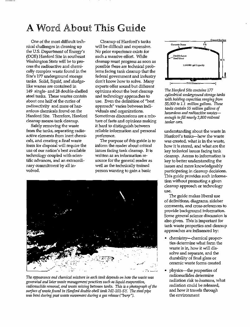
A Word About This Guide One of the most difficult tech
nical challenges in cleaning up the U.S. Department of Energy's (DOE) Hanford Site in southeast Washington State will be to process the radioactive and chemically complex waste found in the Site's 177 underground storage tanks. Solid, liquid, and sludgelike wastes are contained in 149 single- and 28 double-shelled steel tanks. These wastes contain about one half of the curies of radioactivity and mass of hazardous chemicals found on the Hanford Site. Therefore, Hanford cleanup means tank cleanup.
Safely removing the waste from the tanks, separating radioactive elements from inert chemicals, and creating a final waste form for disposal will require the use of our nation's best available technology coupled with scientific advances, and an extraordinary commitment by all involved.
Cleanup of Hartford's tanks will be difficult and expensive. No prior experience exists for such a massive effort. While cleanup must progress as soon as possible there are technical problems facing tank cleanup that the federal government and industry don't know how to solve. Many experts offer sound but different opinions about the best cleanup and technology approaches to use. Even the definition of "best approach" varies between individuals and organizations. Sometimes discussions are a mixture of facts and opinions making it hard to distinguish between reliable information and personal preference.
The purpose of this guide is to inform the reader about critical issues facing tank cleanup. It is written as an information resource for the general reader as well as the technically trained person wanting to gain a basic
Ground Surface
The appearance and chemical mixture in each tank depends on how the waste was generated and later waste management practices such as liquid evaporation, radionuclide removal, and waste mixing between tanks. This is a photograph of the surface of waste found in Hanford double-shell tank 241-101 -SY. The steel pipe was bent during past waste movement during a gas release ("burp").
The Hanford Site contains 177 cylindrical underground storage tanks with holding capacities ranging from 55,000 to 1.1 million gallons. These tanks contain 55 million gallons of hazardous and radioactive wastes-enough to fill nearly 2,800 railroad tanker cars.
understanding about the waste in Hanford's tanks—how the waste was created, what is in the waste, how it is stored, and what are the key technical issues facing tank cleanup. Access to information is key to better understanding the issues and more knowledgeably participating in cleanup decisions. This guide provides such information without promoting a given cleanup approach or technology use.
The guide makes liberal use of definitions, diagrams, sidebar comments, and cross-references to provide background information. Some general science discussion is also given. This is important for tank waste properties and cleanup approaches are influenced by:
• chemistry—chemical properties determine what form the waste is in, how it will dissolve and separate, and the durability of final glass or ceramic waste forms created
• physics—the properties of radionuclides determine radiation risk to humans, what radiation could be released, and how it travels through the environment
• earth science—the properties of soil and groundwater influence how chemical compounds and radionuclides move through the subsurface environment and what technologies could stop or minimize this movement.
Information in this guide is divided into sections that can be read together or separately. More information on participating in Hartford's tank cleanup decisions, including contacts, is provided.
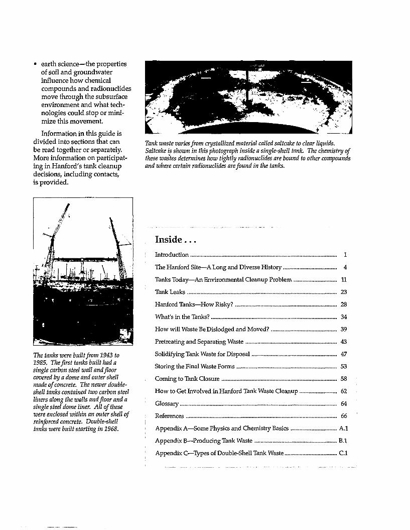
Tank waste varies from crystallized material called saltcake to clear liquids. Saltcake is shown in this photograph inside a single-shell tank. The chemistry of these wastes determines how tightly radionuclides are hound to other compounds and where certain radionuclides are found in the tanks.
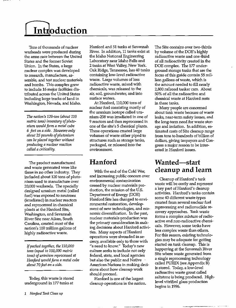
The tanks were built from 1943 to 1985. The first tanks built had a single carbon steel wall and floor covered by a dome and outer shell made of concrete. The newer double-shell tanks contained two carbon steel liners along the walls and floor and a single steel dome liner. All of these were enclosed within an outer shell of reinforced concrete. Double-shell tanks were built starting in 1968.
Ins ide . . . Introduction 1
The Hartford Site—A Long and Diverse History 4
Tanks Today—An Environmental Cleanup Problem 11
Tank Leaks 23
Hanford Tanks—How Risky? 28
What's in the Tanks? 34
How will Waste Be Dislodged and Moved? 39
Pretreating and Separating Waste 43
Solidifying Tank Waste for Disposal 47
Storing the Final Waste Forms 53
Coming to Tank Closure 58
How to Get Involved in Hanford Tank Waste Cleanup 62
Glossary 64
References 66
Appendix A—Some Physics and Chemistry Basics A.l
Appendix B—Producing Tank Waste B.l
Appendix C—Types of Double-Shell Tank Waste C.l
Introduction Tens of thousands of nuclear
warheads were produced during the arms race between the United States and the former Soviet Union. In the States, a large nuclear complex was developed to research, manufacture, assemble, and test nuclear materials and bombs. This complex grew to include 16 major facilities distributed across the United States including large tracks of land in Washington, Nevada, and Idaho.
The nation's 120-ton (about 110 metric tons) inventory ofpluto-nium would form a metal cube 6 feet on a side. However only about 25 pounds ofplutonium can be placed together without producing a nuclear reaction called a criticality.
The product manufactured and waste generated were like those in no other industry. They included about 120 tons of pluto-nium used to manufacture over 20,000 warheads. The specially designed uranium metal (called fuel) was exposed to neutrons (irradiated) in nuclear reactors and reprocessed in chemical plants at the Hanford Site, Washington, and Savannah River Site near Aiken, South Carolina, created most of the nation's 100 million gallons of highly radioactive waste.
If packed together, the 110,000 tons (equal to 100,000 metric tons) of uranium reprocessed at Hanford would form a metal cube about 70 feet on a side.
Today, this waste is stored underground in 177 tanks at
1 Hanford Tank Clean up
Hanford and 51 tanks at Savannah River. In addition, 11 tanks exist at the Idaho National Engineering Laboratory near Idaho Falls and 2 tanks at West Valley, New York. Oak Ridge, Tennessee, has 40 tanks containing low-level radioactive waste. Large volumes of less radioactive waste, mixed with chemicals, was released to the air, soil, groundwater, and into surface waters.
At Hanford, 110,000 tons of nuclear fuel consisting mostly of the uranium isotope called ura-nium-238 was irradiated in one of 9 reactors and then reprocessed in one of the site's 5 chemical plants. These operations created large volumes of waste either piped to structures such as storage tanks, packaged, or released into the environment.
Hanford With the end of the Cold War,
and increasing public concern over environmental contamination caused by nuclear materials production, the mission of the U.S. Department of Energy (DOE) Hanford Site has changed to environmental restoration, development of new technologies, and economic diversification. In the past, nuclear materials production was the primary consideration in making decisions about Hanford activities. Many aspects of Hanford operations were shrouded in secrecy, available only to those with "a need to know." Today's new culture seeks to include not only federal, state, and local agencies but also the public and Native -American Nations in making decisions about how cleanup work should proceed.
Hanford is one of the largest cleanup operations in the nation.
The Site contains over two-thirds by volume of the DOE's highly radioactive waste and one-third of all radioactivity created in the DOE complex. The 177 underground storage tanks that are the focus of this guide contain 55 million gallons of waste, which is the amount needed to fill nearly 2,800 railroad tanker cars. About 50% of all the radioactive and chemical waste at Hanford rests in these tanks.
Many people are concerned about tank waste because of waste leaks, near-term safety issues, and the long-term need for waste storage and isolation. In addition, estimated costs of Site cleanup range from tens to hundreds of billion of dollars, giving taxpayers and Congress a major reason to be interested in Hanford issues.
Wanted—start cleanup and learn
Cleanup of Hanford's tank waste will be costly and represent a key part of Hanford's cleanup activities. Hanford's tanks contain some 40 different waste types created from several nuclear fuel reprocessing and radionuclide recovery approaches. Tank waste forms a complex mixture of radioactive and non-radioactive chemicals. However, some tanks have less complex waste than others. For this reason, existing technologies may be adequate for getting started on tank cleanup. This is happening at the Savannah River Site where waste generated from a single reprocessing technology called PUREX (see Appendix B) is stored. Today, a low-level radioactive waste grout called saltstone is being produced. High-level vitrified glass production begins in 1996.
Location
Tanks
-j&~
J^
Approximate Number of Curies
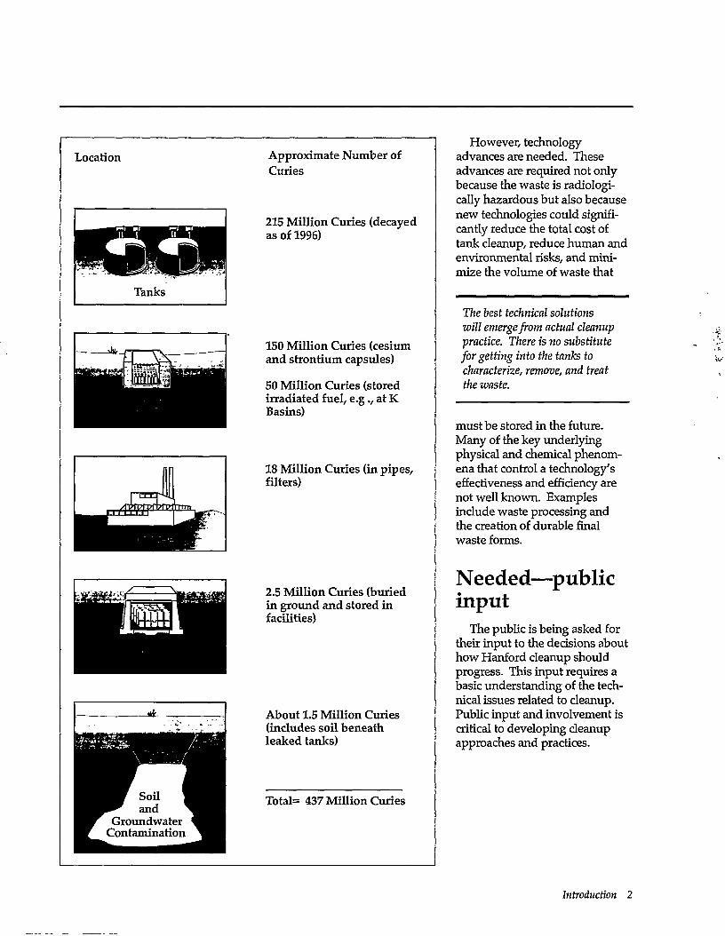
215 Million Curies (decayed as of 1996)
150 Million Curies (cesium and strontium capsules)
50 Million Curies (stored irradiated fuel, e.g., at K Basins)
18 Million Curies (in pipes, filters)
2.5 Million Curies (buried in ground and stored in facilities)
About 1.5 Million Curies (includes soil beneath leaked tanks)
Total= 437 Million Curies
However, technology advances are needed. These advances are required not only because the waste is radiologi-cally hazardous but also because new technologies could significantly reduce the total cost of tank cleanup, reduce human and environmental risks, and minimize the volume of waste that
The best technical solutions will emerge from actual cleanup practice. There is no substitute for getting into the tanks to characterize, remove, and treat the waste.
must be stored in the future. Many of the key underlying physical and chemical phenomena that control a technology's effectiveness and efficiency are not well known. Examples include waste processing and the creation of durable final waste forms.
Needed—public input
The public is being asked for their input to the decisions about how Hanford cleanup should progress. This input requires a basic understanding of the technical issues related to cleanup. Public input and involvement is critical to developing cleanup approaches and practices.
Introduction 2
Managing risks While the intent of cleanup is to reduce human and environmental risk posed by contaminants, waste cleanup activities may also result in increased risks. Cleanup is not risk free. For example,
• How much radiation exposure might workers receive during cleanup?
• Is it better to create large volumes of vitrified glass containing dilute radioactive waste or small volumes of glass containing concentrated waste? Which is easier and safer to monitor and maintain?
; • What are the risk and cost tradeoffs of alternative approaches to tank cleanup?
I • How much risk are we willing to take to get on with tank cleanup using existing technologies?
J These and other cleanup decisions will require that difficult choices be made.
\ The nature of managing risks is making choices, sometimes hard choices. Choices can be made wisely when perti-i nent information is available, such as on cleanup levels, future uses of the land, cleanup approaches, and cost. But ! what information is most critical? How do we know when we have enough information or a technology suitable to
proceed with a decision or action? Those involved in Hanford tank waste cleanup, must bring such information to light so decisions about managing risks can be made wisely.
This guide The sections that follow
describe:
• how Hanford came to be
• tank construction and tank waste
• technical issues affecting the removal of waste from the tanks, processing it, and transforming it into materials that can be safely stored and disposed.
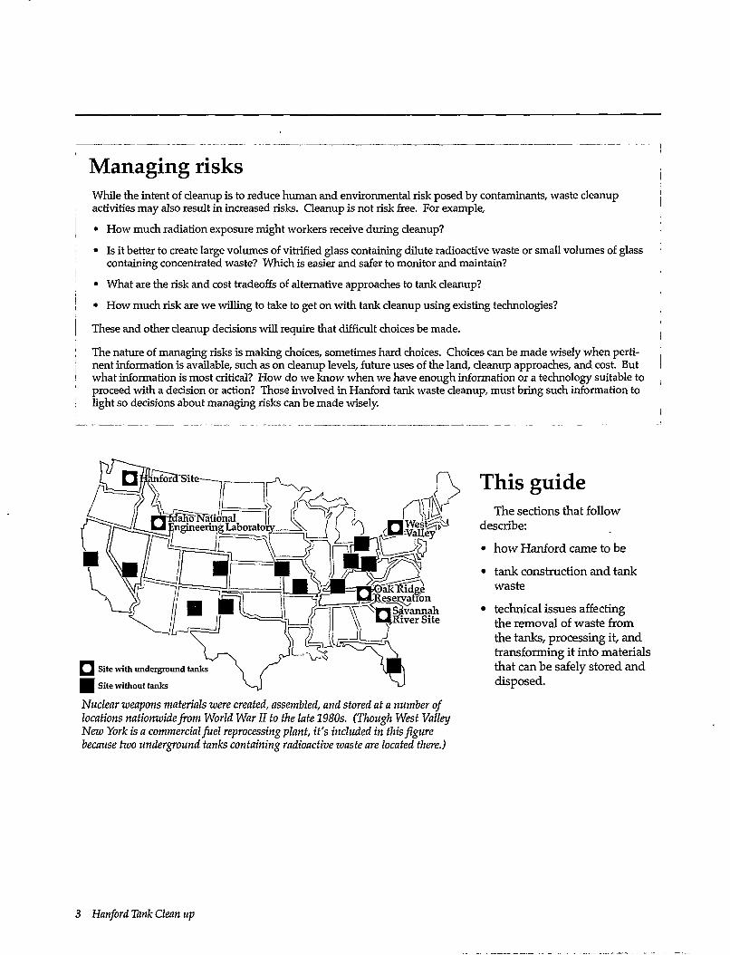
Nuclear weapons materials were created, assembled, and stored at a number of locations nationwide from World War II to the late 1980s. (Though West Valley New York is a commercial fuel reprocessing plant, it's included in this figure because two underground tanks containing radioactive waste are located there.)
3 Hanford Tank Clean up
The Hanford Site—A Loms and Diverse History
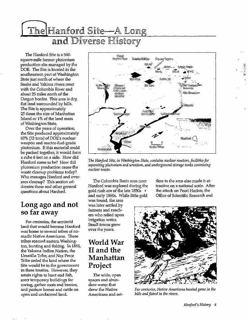
The Hanford Site is a 560-square-mile former plutonium production site managed by the DOE. The Site is located in the southeastern part of Washington State just north of where the Snake and Yakima rivers meet with the Columbia River and about 25 miles north of the Oregon border. This area is dry, flat land surrounded by hills. The Site is approximately 25 times the size of Manhattan Island or 1% of the land mass of Washington State.
Over the years of operation, the Site produced approximately 60% (73 tons) of DOE's nuclear weapon and reactor-fuel-grade plutonium. If this material could be packed together, it would form a cube 6 feet on a side. How did Hanford come to be? How did plutonium production cause the waste cleanup problems today? Who manages Hanford and oversees cleanup? This section addresses these and other general questions about Hanford.
Long ago and not so far away
For centuries, the semiarid land that would become Hanford was home to several tribes of nomadic Native Americans. These tribes roamed eastern Washington, hunting and fishing. In 1855, the Yakama Indian Nation, the Umatilla Tribe, and Nez Perce Tribe ceded the land where the Site would be to the government in three treaties. However, they retain rights to hunt and fish, erect temporary buildings for curing, gather roots and berries, and pasture horses and cattle on open and unclaimed land.
mm mm
'm&. oSS® ^afMi
&sttPttaafo ffisstaav
/ M Stesse
suites < ^^ p - mtem Jam
V ' Stearnsfe
The Hanford Site, in Washington State, contains nuclear reactors, facilities for separating plutonium and uranium, and underground storage tanks containing nuclear waste.
The Columbia Basin area near Hanford was explored during the gold rush era of the late 1850s <> and early 1860s. While little gold was found, the area was later settled by farmers and ranchers who relied upon irrigation water. Small towns grew over the years.
World War II and the Manhattan Project
The wide, open spaces and abundant water that drew the Native Americans and set
tlers to the area also made it attractive on a national scale. After the attack on Pearl Harbor, the Office of Scientific Research and
For centuries, Native Americans hunted game in the hills and fished in the rivers.
Hanford's History 4
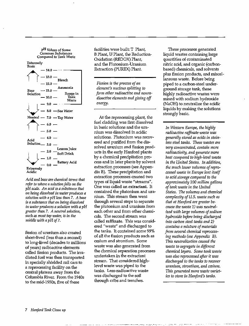
Naturally Occurring Uranium
0.7% U**
9 9 . 3 % U 2 3 8
Uranium in Hanford Irradiated Fuel
Less than 1% U 2 3 5 * Less than 1% other radioactive isotopes
a ^ i H S 8 r *' .
*% varies upon length of time fuel was in nuclear reactor and original composition of fuel.
Uranium isotopes are found in various natural and human-made combinations (given in weight %).
naipURi
Development recommended to President Franklin D. Roosevelt that the Army Corps of Engineers build the industrial facilities needed for a secret weapons project. In June 1942, a new department, the Manhattan Engineer District, was formed within the Corps. This department was headed by General Leslie Groves.
Two materials can be used for nuclear weapons: uranium and plutonium. Uranium is a naturally occurring element, while essentially all plutonium is human-made and is of twentieth century origin. The specific radioactive isotopes most used for making these weapons are uranium-235 and plutonium-239 (see Appendix A). Uranium-235 is separated from naturally occurring uranium and concentrated in large enough quantities to undergo fission in a nuclear weapon. Plutonium-239 is produced in a nuclear reactor by uranium-238 capturing an additional neutron.
Originally, plutonium was to be produced at Clinton (now Oak
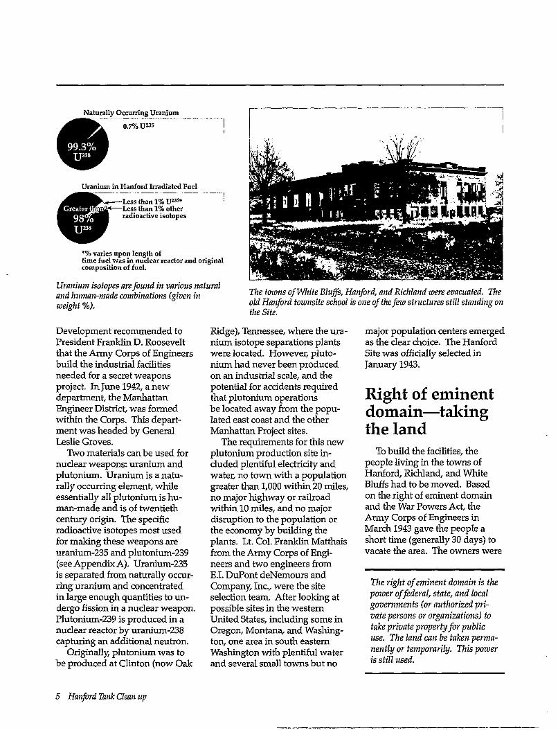
The towns of White Bluffs, Hanford, and Richland were evacuated. The old Hanford townsite school is one of the few structures still standing on the Site.
Ridge), Tennessee, where the uranium isotope separations plants were located. However, plutonium had never been produced on an industrial scale, and the potential for accidents required that plutonium operations be located away from the populated east coast and the other Manhattan Project sites.
The requirements for this new plutonium production site included plentiful electricity and water, no town with a population greater than 1,000 within 20 miles, no major highway or railroad within 10 miles, and no major disruption to the population or the economy by building the plants. Lt. Col. Franklin Matthais from the Army Corps of Engineers and two engineers from E.I. DuPont deNemours and Company, Inc., were the site selection team. After looking at possible sites in the western United States, including some in Oregon, Montana, and Washington, one area in south eastern Washington with plentiful water and several small towns but no
major population centers emerged as the clear choice. The Hanford Site was officially selected in January 1943.
Right of eminent domain—taking the land
To build the facilities, the people living in the towns of Hanford, Richland, and White Bluffs had to be moved. Based on the right of eminent domain and the War Powers Act, the Army Corps of Engineers in March 1943 gave the people a short time (generally 30 days) to vacate the area. The owners were
The right of eminent domain is the power of federal, state, and local governments (or authorized private persons or organizations) to take private properly for public use. The land can be taken permanently or temporarily. This power is still used.
5 Hanford Tank Clean up
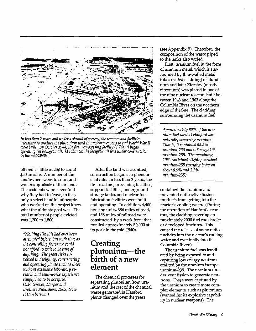
In less than 2 years and under a shroud of secrecy, the reactors and facilities necessary to produce the plutonium used in nuclear weapons to end World War II were built. By October 1944, the first reprocessing facility (T Plant) began operating (in background). U Plant (in the foreground) was under construction in the mid-194Qs.
offered as little as 250 to about $50 an acre. A number of the landowners went to court and won reappraisals of their land. The residents were never told why they had to leave; in fact, only a select handful of people who worked on the project knew what the ultimate goal was. The total number of people evicted was 1,200 to 1,500.
After the land was acquired, construction began at a phenomenal rate. In less than 2 years, the first reactors, processing facilities, support facilities, underground storage tanks, and nuclear fuel fabrication facilities were built and operating. In addition, 4,400 housing units, 386 miles of road, and 158 miles of railroad were constructed by a work force that totalled approximately 50,000 at its peak in the mid-1940s.
Creating plutonium—the birth of a new element
The chemical processes for separating plutonium from uranium and the rest of the chemical waste generated in Hanford plants changed over the years
(see Appendix B). Therefore, the composition of the waste piped to the tanks also varied.
First, uranium fuel in the form of uranium metal, which is surrounded by thin-walled metal tubes (called cladding) of aluminum and later Zircaloy (mostly zirconium) was placed in one of the nine nuclear reactors built between 1943 and 1963 along the Columbia River on the northern edge of the Site. The cladding surrounding the uranium fuel
Approximately 80% of the uranium fuel used at Hanford was naturally occurring uranium. That is, it contained 99.3% uranium-238 and 0.7 weight % uranium-235. The remaining 20% contained slightly enriched uranium-235 (varying between about 0.9% and 1.2% uranium-235).
contained the uranium and prevented radioactive fission products from getting into the reactor's cooling water. (During the operation of Hanford's reactors, the cladding covering approximately 2000 fuel rods broke or developed fractures. This caused the release of some radionuclides into the reactor's cooling water and eventually into the Columbia River.)
The uranium fuel was irradiated by being exposed to and capturing low energy neutrons emitted by the uranium isotope uranium-235. The uranium underwent fission to generate neutrons. These were captured by the uranium to create more complex elements, such as plutonium (wanted for its explosive capability in nuclear weapons). The
"Nothing like this had ever been attempted before, but with time as the controlling factor we could not afford to wait to be sure of anything. The great risks involved in designing, constructing and operating plants such as these without extensive laboratory research and semi-works experience simply had to be accepted." (L.R. Groves, Harper and Brothers Publishers, 1962, Now It Can be Told.)
Hanford's History 6
pH Values of Some Common Substances
Compared to Tank Waste Extremely Basic
— 14.0 — A: — 13.0 —
Bleach —12.0 —
Ammonia Base — 11.0 — Solution Range in
— 10.0 — Tank Waste
— 9.0 u 8.0 —Sea Water
Neutral — 7.0 —Tap Water
1 I — 5.0 —
— 4.0 — Acid Solution 3_o
— 2.0 — Lemon Juice Soft Drink
— 1.0 — Battery Acid
— 0.0 — Extremely Acidic
Acid and base are chemical terms that refer to where a solution falls on the pH scale. An acid is a substance that on being dissolved in water produces a solution with a pH less than 7. A base is a substance that on being dissolved in water produces a solution with a pH greater than 7. A neutral solution, such as most tap water, is in the middle with a pH of 7.
fission of uranium also created short-lived (less than a second) to long-lived (decades to millions of years) radioactive elements called fission products. The irradiated fuel was then transported in specially shielded rail cars to a reprocessing facility on the central plateau away from the Columbia River. From the 1940s to the mid-1950s, five of these
facilities were built: T Plant, B Plant, U Plant, the Reduction-Oxidation (REDOX) Plant, and the Plutonium-Uranium Extraction (PUREX) Plant.
Fission is the process of an element's nucleus splitting to form other radioactive and nonradioactive elements and giving off energy.
At the reprocessing plant, the fuel cladding was first dissolved in basic solutions and the uranium was dissolved in acidic solutions. Plutonium was recovered and purified from the dissolved uranium and fission products in the early Hanford plants by a chemical precipitation process and in later plants by solvent extraction processes (see Appendix B). These precipitation and extraction processes created two types of liquid waste "streams". One was called an extractant. It contained the plutonium and uranium. This stream then went through several steps to separate the plutonium and uranium from each other and from other chemicals. The second stream was called raff inate. This was considered "waste" and discharged to the tanks. It contained some 99% of all the fission products such as cesium and strontium. Some waste was also generated from the chemical separation processes undertaken in the extractant stream. That considered high-level waste was piped to the tanks. Less-radioactive waste was discharged to the soil through cribs and trenches.
These processes generated liquid wastes containing large quantities of contaminated nitric acid, and organic (carbon-based) chemicals, and solvents plus fission products, and miscellaneous waste. Before being piped to a carbon-steel underground storage tank, these highly radioactive wastes were mixed with sodium hydroxide (NaOH) to neutralize the acidic liquids by making the solutions strongly basic.
In Western Europe, the highly radioactive raffinate waste was generally stored as acids in stainless steel tanks. These wastes are very concentrated, contain more radioactivity, and generate more heat compared to high-level waste in the United States. In addition, the much lower volumes of reprocessed waste in Europe lent itself to acid storage compared to the approximately 100 million gallons of tank waste in the United States. The volumes and chemical complexity of U.S. waste such as that at Hanford are greater because the waste 1) was neutralized with large volumes of sodium hydroxide before being discharged into carbon steel tanks and 2) contains a mixture of materials from several chemical reprocessing methods (see Appendix B). This neutralization caused the waste to segregate in different chemical layers. Some tank waste was also reprocessed after it was discharged to the tanks to recover uranium, strontium, and cesium. This generated more waste varieties to store in Hanford's tanks.
7 Hanford Tank Clean up
During World War II, pluto-nium nitrate paste was shipped to Los Alamos, New Mexico, where it was converted to a dense (50% more dense than lead) 11-pound silver colored plutonium metal sphere that was incorporated into the first nuclear bombs. Starting in 1959, Hartford's Plutonium Finishing Plant (also known as Z Plant) started converting plutonium nitrate solutions to a plutonium metal.
Self rule Hartford's goal was to
produce plutonium in sufficient quantities to meet military defense needs. Long-term waste management considerations were less important. The thought was that the waste would be taken care of later. As in waste management practices of other industries common at the time, Hartford's waste was managed in ways that are not acceptable by today's standards.
Local growth Work at the Hartford Site fu
eled the local economy, and the surrounding towns grew. The 1993 population estimates for the three major towns closest to the Hartford Site are Richland with 34,080 people, Kennewick with 45,100, and Pasco with 21,370. The total population of the other towns within 20 miles of the Site is 10,900. In and around the Tri-Cities, the land is used for urban and industrial development, irrigated and dryland farming, and raising livestock.
Hanford—people and rules
Today, the Site is managed by the DOE, a federal agency, which contracts with other companies to do research, manage and operate the Site, and protect workers' health. Currently (1995), the three contractors are Westinghouse Hanford Com
pany; Bechtel Hanford, Inc.; and the Hanford Environmental Health Foundation. Pacific Northwest Laboratory is also located adjacent to the Hanford Site. Westinghouse Hanford Company manages the tanks and facilities, and provides many Site support services. Also, Westinghouse Hanford Company administers 1) ICF Kaiser Hanford Company's
Definitions of various types of waste differ between government agencies. The following definitions are used in this guide:
High-level waste (HLW) is waste from the reprocessing (chemical separation) of uranium and plutonium from other non-desired radioactive elements. High-level waste contains most of the radioactive elements discharged as waste to the underground tanks.
Low-level waste (LLW) is a catch-all category for any radioactive waste that is not spent fuel, high-level, or containing large amounts of transuranic (for example, plutonium) waste. It can include liquid waste or contaminated clothing, tools, and equipment.
Hazardous waste is nonradioactive waste, such as metals (for example, lead and mercury) and chemical compounds (for example, tributyl phosphate), that is known or thought to pose a risk to the environment and people's health.
Mixed waste is radioactive material combined with hazardous waste.
Transuranic waste is radioactive waste that contains more than 100 nanocuries per gram (100 billionths of a curie per gram) of alpha-emitting isotopes having atomic numbers greater than 92 (that means the number of protons in nucleus is greater than found in uranium) and half lives greater than 20 years. Such waste results primarily from nuclear fuel reprocessing and from the manufacturing of plutonium weapons.
Depending on the source, radioactive waste is regulated by DOE (military sources) or the U.S. Nuclear Regulatory Commission (commercial sources). Hazardous waste is regulated by the EPA. Mixed waste regulation is challenging because the radioactive components (if generated by military sources) are regulated by DOE and the hazardous chemicals are regulated by the EPA.
Hanford's History 8
contract for managing site services such as architectural, construction, and engineering support and 2) Boeing Computer Services-Richland for some communication and information site services. Bechtel Hanford, Inc., plans, manages, and executes a wide range of environmental restoration activities that include cleaning up soil, groundwater, solid waste, and facilities identified for decontamination and decommissioning. The Hanford Environmental Health Foundation educates the staff about preventive medicine and provides basic first-aid and health services as well as tracking worker health. Pacific Northwest Laboratory is a national multiprogram laboratory for DOE focusing on broad environmental, energy, economic, and national security issues as well as on the Hanford cleanup mission.
The work of DOE and contractors on the Site is bound by federal, state, and local environmental laws and agreements. Key examples include the Comprehensive Environmental Response, Compensation, and Liability Act (CERCLA), Hanford Federal Facility Agreement and Consent Order (commonly called the Tri-Party Agreement), and Resource Conservation and Recovery Act (RCRA). Briefly, CERCLA (also known as Super-fund) imposes cleanup and reporting requirements for remediating hazardous waste sites, such as leaks to the soil from the tanks. RCRA regulates management of hazardous waste at active waste treatment, storage, and disposal facilities to avoid
creating new Superfund sites in the future. The Tri-Party Agreement is an agreement among the Washington State Department of Ecology, U.S. Environmental Protection Agency (EPA) Region 10, and DOE that legally requires DOE to safely manage and dispose of liquid and solid wastes on the Site. The agreement also requires DOE to cleanup contamination found in the environment and in engineered structures such as reprocessing plants and tanks. The Tri-Party Agreement contains milestones for tracking cleanup progress. A milestone is a provision that calls for cleanup activities to be done by specific dates. These milestones may be extended and new ones added. In the agreement, the tanks are labelled as active treatment, storage, and disposal units, which means that DOE is required to manage the waste from generation to final disposal under the RCRA.
Another law that is an integral part of the rules governing the tanks is Public Law 101-510, Section 3137, commonly called the Wyden Bill after the U.S. Representative Ron Wyden, who sponsored it. This law requires the DOE to identify and monitor Hanford Site tanks that require special safety precautions because increases in temperature or pressure could result in the uncontrolled release of radionuclides. These tanks are called Watch List tanks. This monitoring may require new equipment to be installed. Further, DOE is required to develop plans to deal with excessive temperature,
excessive pressure, or a release from any Watch List tank. High-level waste cannot be added to watch-list tanks, except for small amounts used in analyses, unless a safer alternative does not exist.
As of July 1995, the high-priority safety issues identified in the Wyden Bill involve a total of 48 single-shell tanks and 6 double-shell tanks. Ten tanks are listed for more than one reason.
The number of tanks on the Watch List changes. For example, in May 1994,10 tanks were added to the list because a reassessment of the historical records showed that the concentration of organic compounds was greater than the allowed limit. In January 1995, two tanks were removed from the list because waste disposal records showed they did not receive waste containing ferrocya-nide, one of the waste constituents which might ignite.
Federal and state agencies are not the only organizations involved in making decisions about the Hanford Site. In the signed treaties and agreements, the Native American Nations have a government-to-government relationship with federal agencies. The Yakama Indian Nation and the Confederated Tribes of the Umatilla Indian Reservation advise the DOE's Richland Operations Office and DOE-Headquarters through direct consultation; they may also participate in formal groups at
9 Hanford Tank Clean up
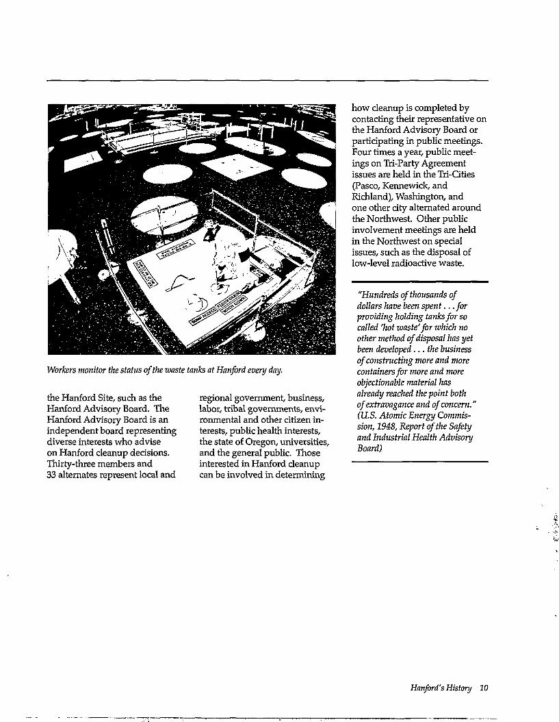
Workers monitor the status of the waste tanks at Hanford every day.
the Hanford Site, such as the Hanford Advisory Board. The Hanford Advisory Board is an independent board representing diverse interests who advise on Hanford cleanup decisions. Thirty-three members and 33 alternates represent local and
regional government, business, labor, tribal governments, environmental and other citizen interests, public health interests, the state of Oregon, universities, and the general public. Those interested in Hanford cleanup can be involved in determining
how cleanup is completed by contacting their representative on the Hanford Advisory Board or participating in public meetings. Four times a year, public meetings on Tri-Party Agreement issues are held in the Tri-Cities (Pasco, Kennewick, and Richland), Washington, and one other city alternated around the Northwest. Other public involvement meetings are held in the Northwest on special issues, such as the disposal of low-level radioactive waste.
"Hundreds of thousands of dollars have been spent. ..for providing holding tanks for so called 'hot waste'for which no other method of disposal has yet been developed.. .the business of constructing more and more containers for more and more objectionable material has already reached the point both of extravagance and of concern.' (U.S. Atomic Energy Commission, 1948, Report of the Safety and Industrial Health Advisory Board)
Hanford's History 10
Tanlkg Today—An Environmental Cleanup Problem.
Much of the waste created from the production of pluto-nium at Hanford is stored in 177 underground tanks. How big are the tanks? How were they constructed and operated? What do they contain? This section addresses these and other questions about the Hanford tanks.
"To reduce costs, the U.S. Government built carbon steel tanks (rather than stainless steel tanks) for storing high-level radioactive waste which was made alkaline by adding sodium hydroxide." (from: "Plutonium: Deadly Gold of the Nuclear Age." International Physicians Press, 1992)
There was also an acute shortage of stainless steel during World War II.
Tank construction Hartford's tanks are cylindrical
reinforced concrete structures with inner carbon steel liners. Tanks are split into two groups based on their design: 149 tanks have a single carbon steel liner and 28 tanks have two steel liners separated by a space called the annulus. The annulus provides a margin of safety in the case of leaks because the leak can be detected and the waste removed before it might escape and enter the underlying soil. The domes of the single-shell tanks are made of concrete without a steel inner
liner. The double-shell tanks are completely enclosed by steel and reinforced by a concrete shell. Both single-shell tanks and double-shell tanks are covered with about 10 feet of soil and gravel.
The total amount of waste in the tanks is approximately 55 million gallons. The volume of waste in the tanks changes for several reasons, including 1) water evaporation, 2) waste transfers between tanks, 3) waste discharge from laboratories and cleanout of production facilities, and 4) pipeline flushes. Water is flushed through pipes for several
reasons, such as to prevent line plugging. For example, in June 1994, pipeline flushing added approximately 62,000 gallons of water to the double-shell tanks.
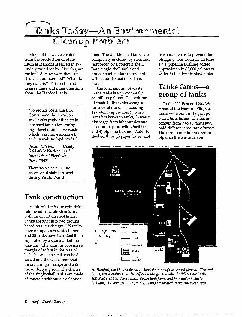
Tanks farms—a group of tanks
In the 200-East and 200-West Areas of the Hanford Site, the tanks were built in 18 groups called tank farms. The farms contain from 2 to 16 tanks and hold different amounts of waste. The farms contain underground pipes so the waste can be
At Hanford, the 18 tank farms are buried on top of the central plateau. The tank farms, reprocessing facilities, office buildings, and other buildings are in the 200-East and 200-West Areas. Seven tank farms and four major facilities (T Plant, U Plant, REDOX, and Z Plant) are located in the 200 West Area.
11 Hanford Tank Clean up
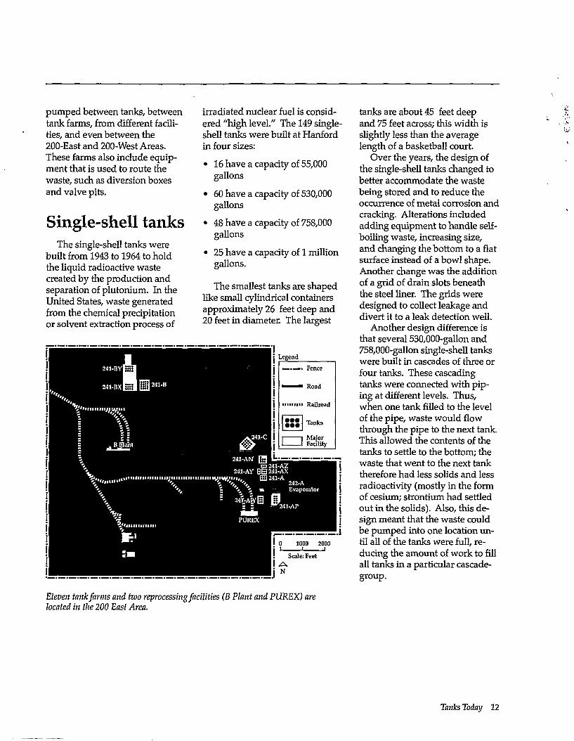
pumped between tanks, between tank farms, from different facilities, and even between the 200-East and 200-West Areas. These farms also include equipment that is used to route the waste, such as diversion boxes and valve pits.
Single-shell tanks The single-shell tanks were
built from 1943 to 1964 to hold the liquid radioactive waste created by the production and separation of plutonium. In the United States, waste generated from the chemical precipitation or solvent extraction process of
irradiated nuclear fuel is considered "high level." The 149 single-shell tanks were built at Hanford in four sizes:
• 16 have a capacity of 55,000 gallons
• 60 have a capacity of 530,000 gallons
• 48 have a capacity of 758,000 gallons
• 25 have a capacity of 1 million gallons.
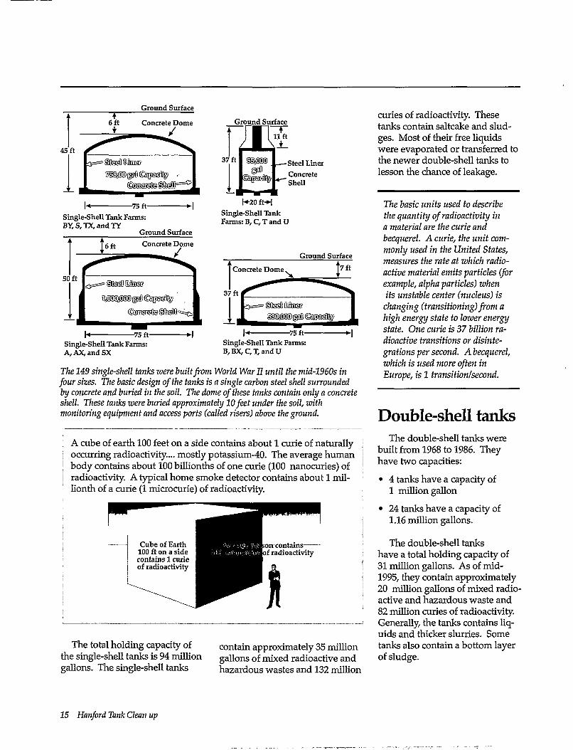
The smallest tanks are shaped like small cylindrical containers approximately 26 feet deep and 20 feet in diameter. The largest
tanks are about 45 feet deep and 75 feet across; this width is slightly less than the average length of a basketball court.
Over the years, the design of the single-shell tanks changed to better accommodate the waste being stored and to reduce the occurrence of metal corrosion and cracking. Alterations included adding equipment to handle self-boiling waste, increasing size, and changing the bottom to a flat surface instead of a bowl shape. Another change was the addition of a grid of drain slots beneath the steel liner. The grids were designed to collect leakage and divert it to a leak detection well.
Another design difference is that several 530,000-gallon and 758,000-gallon single-shell tanks were built in cascades of three or four tanks. These cascading tanks were connected with piping at different levels. Thus, when one tank filled to the level of the pipe, waste would flow through the pipe to the next tank. This allowed the contents of the tanks to settle to the bottom; the waste that went to the next tank therefore had less solids and less radioactivity (mostly in the form of cesium; strontium had settled out in the solids). Also, this design meant that the waste could be pumped into one location until all of the tanks were full, reducing the amount of work to fill all tanks in a particular cascade-group.
Eleven tank farms and two reprocessing facilities (B Plant and PUREX) are located in the 200 East Area.
Tanks Today 22
T-Tank Farm 12 @ 530,000 gal
4 @ 55,000 gal
TY-Tank Farm 6 @ 758,000 gal
TX-Tank Farm 18 @ 530,000 gal
U-TankFarm 12 @ 530,000 gal
4 @ 55,000 gal
S-Tank Farm 12 @ 758,000 gal
SX-Tank Farm 15 @ 1,000,000 gal
N
I I Reprocessing Plant
^ Tank Farms
O Single-Shell Tank
0 Double-Shell Tank
F^ Pipelines (examples)
| | Support Structures
Cross-Transfer -+- Lines to the
200 East Area
SY-TankFarm 3 @ 1,160,000
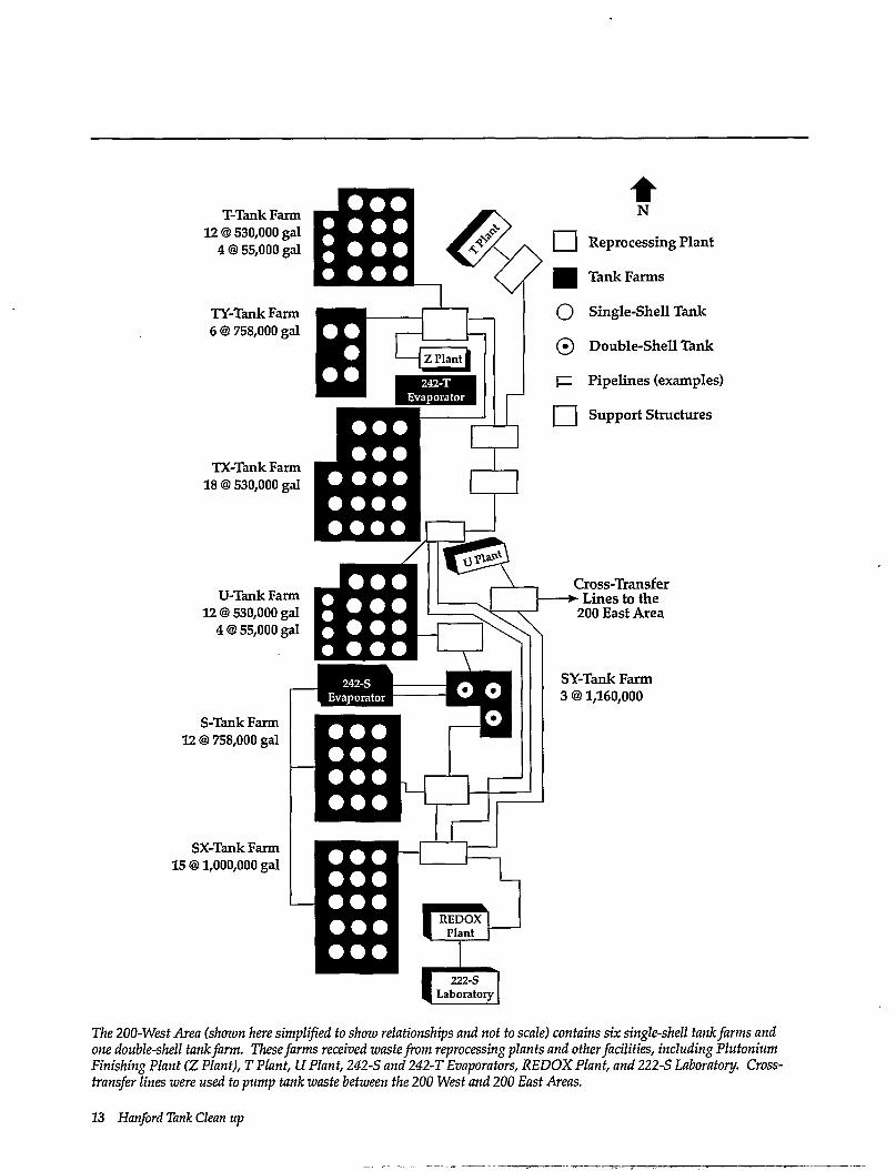
The 200-West Area (shown here simplified to show relationships and not to scale) contains six single-shell tank farms and one double-shell tank farm. These farms received waste from reprocessing plants and other facilities, including Plutonium Finishing Plant (Z Plant), T Plant, U Plant, 242-S and 242-T Evaporators, REDOX Plant, and 222-S Laboratory. Cross-transfer lines were used to pump tank waste between the 200 West and 200 East Areas.
13 Hanford Tank Clean up
BY-TankFarm 12 @ 758,000 gal
B-Tank Fann 12 ©530,000 gal 4 @ 55,000 gal
C-Tank Fann 12 @ 530,000 gal 4 @ 55,000 gal
Cross-Transfer Lines to the -+
200 West Area
N
I J Reprocessing Plant
^M Tank Farms
O Single-Shell Tank
0 Double-Shell Tank
F^ Pipelines (examples)
| | Support Structures
AN-Tank Farm 7 ©1,160,000 gal
AZ-Tank Farm 2 @ 1,000,000 gal
AX-Tank Farm 4 @ 1,000,000 gal
A-Tank Farm 6 @ 1,000,000 gal
o o o o o o o o
AP-Tank Farm 8 ©1,160,000 gal
AW-Tank Farm 6 © 1,160,000 gal
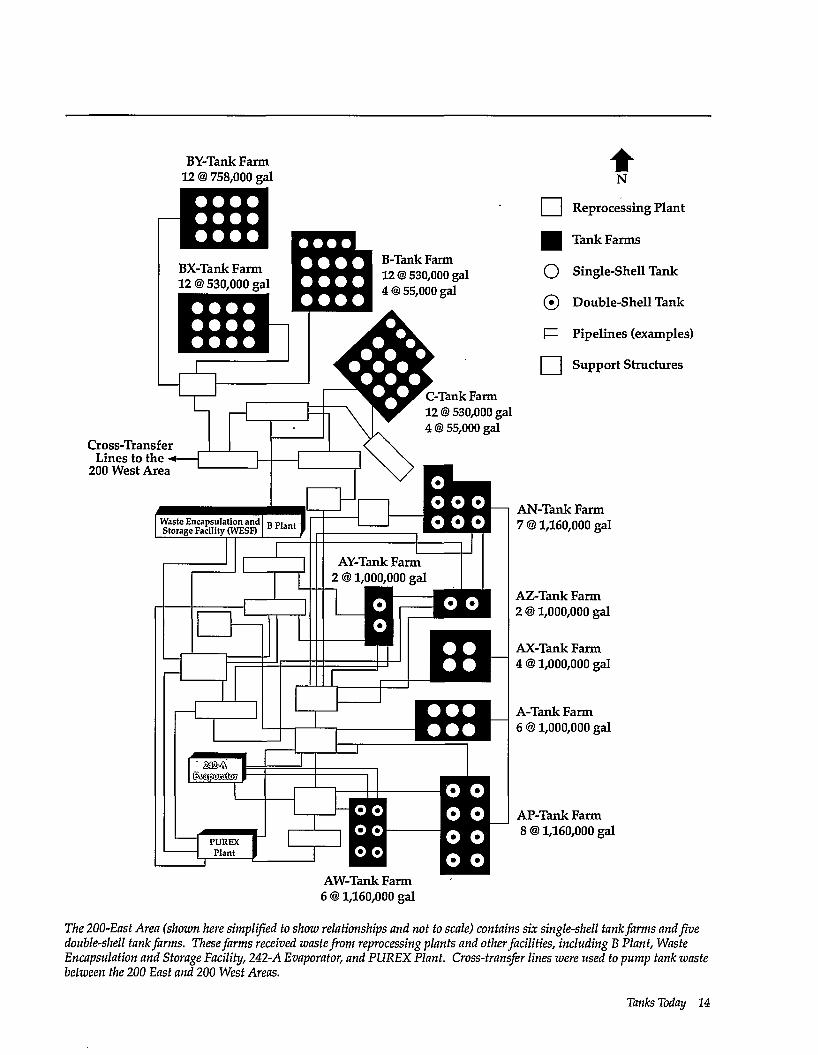
The 200-East Area (shown here simplified to show relationships and not to scale) contains six single-shell tank farms and five double-shell tank farms. These farms received waste from reprocessing plants and other facilities, including B Plant, Waste Encapsulation and Storage Facility, 242-A Evaporator, and PUREX Plant. Cross-transfer lines were used to pump tank waste between the 200 East and 200 West Areas.
Tanks Today 14
Ground Surface
Concrete Dome /
45 ft
Ground Surface
37 ft Steel Liner Concrete Shell
Single-Shell Tank Farms: BY,S,TX,andTY
Ground Surface
r*20 ft-H Single-Shell Tank Farms: B, C, T and U
Ground Surface
Single-Shell Tank Farms: A, AX, and SX
Single-Shell Tank Farms: B,BX,C,T,andU
The 149 single-shell tanks were built from World War II until the mid-1960s in four sizes. The basic design of the tanks is a single carbon steel shell surrounded by concrete and buried in the soil. The dome of these tanks contain only a concrete shell. These tanks were buried approximately 10 feet under the soil, with monitoring equipment and access ports (called risers) above the ground.
A cube of earth 100 feet on a side contains about 1 curie of naturally occurring radioactivity.... mostly potassium-40. The average human body contains about 100 billionths of one curie (100 nanocuries) of radioactivity. A typical home smoke detector contains about 1 millionth of a curie (1 microcurie) of radioactivity.
The total holding capacity of the single-shell tanks is 94 million gallons. The single-shell tanks
contain approximately 35 million gallons of mixed radioactive and hazardous wastes and 132 million
curies of radioactivity. These tanks contain saltcake and sludges. Most of their free liquids were evaporated or transferred to the newer double-shell tanks to lesson the chance of leakage.
The basic units used to describe the quantity of radioactivity in a material are the curie and becquerel. A curie, the unit commonly used in the United States, measures the rate at which radioactive material emits particles (for example, alpha particles) when its unstable center (nucleus) is changing (transitioning) from a high energy state to lower energy state. One curie is 37 billion radioactive transitions or disintegrations per second. A becquerel, which is used more often in Europe, is 1 transition/second.
Double-shell tanks The double-shell tanks were
built from 1968 to 1986. They have two capacities:
• 4 tanks have a capacity of 1 million gallon
• 24 tanks have a capacity of 1.16 million gallons.
The double-shell tanks have a total holding capacity of 31 million gallons. As of mid-1995, they contain approximately 20 million gallons of mixed radioactive and hazardous waste and 82 million curies of radioactivity. Generally, the tanks contains liquids and thicker slurries. Some tanks also contain a bottom layer of sludge.
15 Hanford Tank Clean up
Single-shell tank waste at a glance 149 tanks
• 55,000 to 1 million gallon capacities • 94 million gallon total capacity (originally)
35 million gallons of waste • 23 million gallons of saltcake (moist water-soluble salts like sodium nitrate) • 12 million gallons of sludge (mixture of water and insoluble salts and salt-containing liquids) • average density is 1.6 grams per cubic centimeter
Waste contains • 190,000 tons of chemicals
- 90% sodium nitrates and sodium nitrites - rest as metal (for example, aluminum) phosphates, carbonates, hydroxides, sulfates
• 12 million gallons of drainable and nondrainable water
132 million curies (decayed to the year 1996) • 75% of radioactivity from strontium-90 • 24% of radioactivity from cesium-137 • rest of radionuclides contribute about 1% of total radioactivity • most strontium in sludge • most cesium in saltcake and interstitial liquids
Note: These are rounded numbers and estimates. Values are based upon irradiated fuel reprocessing records, chemical procurement records, and some waste sample analyses.
Liquid Observation
A "typical" single-shell tank has access ports and risers available for monitoring or other entry needs such as waste sampling. Risers suitable for waste sampling are very limited.
Tanks Today
Double-shell tank waste at a glance 28 tanks
• 1.0 to 1.1 million gallon capacities • 31 million gallon total capacity
20 million gallons of waste (see Appendix C for summary of waste types) • 25% low-level radioactive waste not containing complex organic compounds • 30% thick to thin liquid waste with concentrated salts generated from evaporating supernatant liquids • 20% waste containing high concentrations of complex organic compounds • 10% from PLTREX Plant alkaline waste generated from reprocessing N Reactor irradiated fuel • 15% from other sources • average density is 1.5 grams per cubic centimeter
Waste contains • 55,000 tons of chemicals
- 70% sodium nitrates and sodium nitrites - 20% metal hydroxides - rest as metal phosphates, carbonates, oxides, sulfates
• 17 million gallons of water 82 million curies (decayed to the year 1996)
• 72% of radioactivity from cesium-137 • 27% of radioactivity from strontium-90 • rest of radionuclides contribute about 1% of total radioactivity • most strontium in sludge • most cesium in slurry and supernatant liquid
Note: These are rounded numbers and estimates. Values are based upon irradiated fuel reprocessing records, chemical procurement records, and some waste sample analyses.
A "typical" double-shell tank has many access ports and risers used for monitoring the tank and surrounding environment. These access points provide openings for sampling the waste.
Hanfbrd Tank Clean up
Something of a mystery—tank contents
The radioactive and chemical contents of individual tanks are not well known. SomeHanford documents refer to "limited tank sample data" when summarizing our knowledge of tank waste characteristics. Most tank waste was generated from the reprocessing of irradiated uranium (in nuclear fuel) to extract pluto-
nium and recover uranium for recycling. Different chemical processes were used, which added chemicals including organic compounds (for example, hexone, tributyl phosphate, or kerosene) and salts of various metals such as bismuth, iron, and aluminum. Before the acidic waste was discharged to the tanks, it was neutralized with sodium hydroxide (NaOH) because the acid would corrode the carbon-steel tank; this process added large quantities of sodium. Over
Ground Surface
Concrete Dome
55 ft - Steel Liner Concrete Shell'
1,160,000 gal Capacity
. Primary Insulating Tank /Concrete
-75 ft-H Double-Shell Tank Farms: AN, AP, AW, AY, AZ, and SY
The 28 double-shell tanks were designed to provide better -protection from leaks than the single-shell tanks.
Waste concentrators The first tank waste concentrators, called 242-B and 242-T, went into operation in 1951. They were steam-heated pot-like evaporators operated at atmospheric pressure outside the tanks. Waste was piped from the single-shell tanks and into these concentrators to partially boil down the liquids. Slightly concentrated waste was then returned to the tanks where solids precipitated as the solutions cooled.
Another early Hanford technique involved heating the tank's liquids from inside the tank. One approach used an electric heater inserted directly into the waste. The heated waste was then circulated into other tanks. A second approach involved circulating hot air in an individual tank through a perforated pipe.
Evaporators such as the 242-A Evaporator located near the PUREX Plant in the 200 East Area are used to boil off water from tank waste, reducing the volume.
The operation of the 242-S (located in 200-West Area near the REDOX Plant) and 242-A Evaporator-Crystallizers (located in 200-East Area near PUREX Plant) began in 1973 and 1977, respectively. These evaporators were used to boil off water from the tank liquids at a much larger scale than previous techniques. This was accomplished by pumping liquids from the tanks and into the evaporator. Evaporation was carried out under a vacuum; salt crystals were precipitated and grown in the evaporator-crystallizer. Evaporation was carried out until a thick slurry was created containing about 30% by weight of solids. The slightly hot, concentrated slurry was then piped back into a tank where it cooled, crystallized, and or settled to the tank's bottom. When cooled, this solution produced a more permeable saltcake than previous evaporation techniques. The principal product of evaporation was a large volume of sodium nitrate (NaN03) saltcake and thick slurry's rich in chemical compounds such as sodium hydroxide (NaOH) and sodium aluminate (N^AlflJ. Between 1950 and 1995, approximately 203 million gallons of liquids were evaporated from Hanford's tank waste.
Tanks Today 18
the years, portions of the waste were also put through other chemical extraction processes to remove radioactive elements, such as uranium, cesium, and strontium (Appendix B). These neutralization and radionuclide-scavenging processes added other chemicals, making the waste more chemically complex. Miscellaneous materials such as organic ion exchange resin, plastic bottles, and metal parts (for example, steel tapes used to
measure waste levels) are also found in the tanks. In addition, cement and diatomaceous earth were once added to some single-shell tanks to soak up liquids to "stabilize" the tanks. When these materials mixed with the tank liquids, they formed hard crystalline layers rich in aluminum and silica. All these materials add to the difficulties of taking and analyzing samples that are representative of a single tank or group of tanks. Records were sometimes
not kept about the contents of the waste and how much of it was transferred between tanks or tank farms.
Layers of waste The waste in the tanks has
separated into sometimes distinct and other times interfingered layers. The thickness, physical characteristics, and chemical composition of these layers vary between tanks depending on how the waste was generated, processed, reprocessed and mixed. The following are generalized descriptions of the chemical mixture that is sometimes best described in terms of exceptions rather than rules. In general the different layers are:
• supernatant liquid: a clear liquid that can be easily pumped; generally floats above a layer of settled solids.
• interstitial liquid: liquid sometimes found within the pore spaces of saltcake and sludges.
• sludge: a thick layer containing water-insoluble chemicals precipitated or settled to the bottom of a tank when the reprocessing plant's acidic liquid waste was made basic by adding sodium hydroxide or other various in-tank or waste concentration processes were performed. Sludges tend to have small pore spaces not allowing liquids to be easily drained or pumped because of high capillary forces.
Double-Shell Tank
Radionuclides
Cesium Technetium Strontium (Trace) Transuranics (Trace)
Strontium Transuranics
Air with Small Amounts of Hydrogen, Nitrous Oxide,
Ammonia and Water Vapor
lixspsssatesoij h&tfsM
Chemicals
Nitrates Nitrites
~ .. I Phosphates Sodium r" A i U I r ?ir , a ,es
Carbonates Sulfates
Sludge i Single-Shell Tank
Aluminum-] H d r o x i d c s
™ I Okies UraniZ [ gjg£«-
Zirconium J b u I I a t e s
Radionuclides Chemicals
Cesium Technetium Iodine
Strontium Plutonium Technetium
Air with Small Amounts of Hydrogen, Nitrous Oxide, Ammonia and Water Vapor
Saltcake and Interstitial Liquid
Sludge
Nitrates Nitrites Phosphates Aluminates Carbonates Sulfates
Aluminum j Silicon Hydroxides
_. I r o " [ Oxides Bismuth f p h o s p h a t e s
Uranium r
Zirconium J
The tanks contain numerous radionuclides and chemicals that have separated into blended layers. The contents of any individual tank can significantly vary from these two idealized illustrations.
19 Hanford Tank Clean up
Strontium, cesium, and other tank waste radioactivity All naturally occurring cesium occurs as the stable (nonradioactive) element cesium-133. (The number 133 is cesium's atomic weight—that is, the total number of protons and neutrons in the atom's nucleus (see Appendix A). Radioactive cesium also exits. Those isotopes with half lives greater than one year include cesium-134 (2 years), -135 (2 million years), and -137 (30 years). Cesium-137 is the primary cesium radioisotope in the tank waste.
Naturally occurring strontium consists of four stable isotopes (strontium-84, -86, -87, -88). Strontium-88 makes up most (83%) of all naturally occurring strontium. Radioactive strontium also exists. The single isotope having a half life greater than 1 year is strontium-90 (29 years). This is also the primary strontium radioisotope existing in the tank waste.
About 99% of the radioactivity in Hanford's tank waste comes from the longest lived of these radioisotopes: cesium-137 and strontium-90. After 10 half-lives, these isotopes will have essentially decayed away. Therefore, in about 300 years (10 half-lives times 30 years), all but 0.1% of the cesium-137 in the tank waste will have decayed to a stable (nonradioactive) element called barium-137. Over the same time, all but about 0.1% of the strontium-90 will have decayed to the stable element zirconium-90.
After approximately 850 years (28 half-lives), 1 curie remains from the nearly 215 million curies of strontium and cesium found today in Hanford's tanks. After 300 or more years, the radioisotopes of concern in Hanford's tanks will not be cesium and strontium but rather those isotopes having long half-lives. These (along with their half-lives) include plutonium-239 (24,000 years), americium-241 (432 years), and technetium-99 (210,000 years). There is an estimated 200,000 curies of these long-lived radioisotopes in the tank waste. For comparison, the radioactivity from these longer-lived radionuclides equals less than 1 / 10th of 1% of all radioactivity now contained in Hanford's tanks.
saltcake: is a moist material (sometimes like wetbeach sand) created from the crystallization and precipitation of chemicals after the supernatant liquid was evaporated. Saltcake is usually made of water-soluble chemicals. It must be broken into pieces or dissolved to be removed from a tank. The pore spaces in saltcake tend to be relatively large and therefore allow liquids to be drained or be pumped because of low capillary forces.
slurry: a mixture of solid particles suspended in a liquid. While slurry can be pumped, changes in pH, temperature, or chemical composition can cause it to turn into a thick paste capable of plugging pipes and filters.
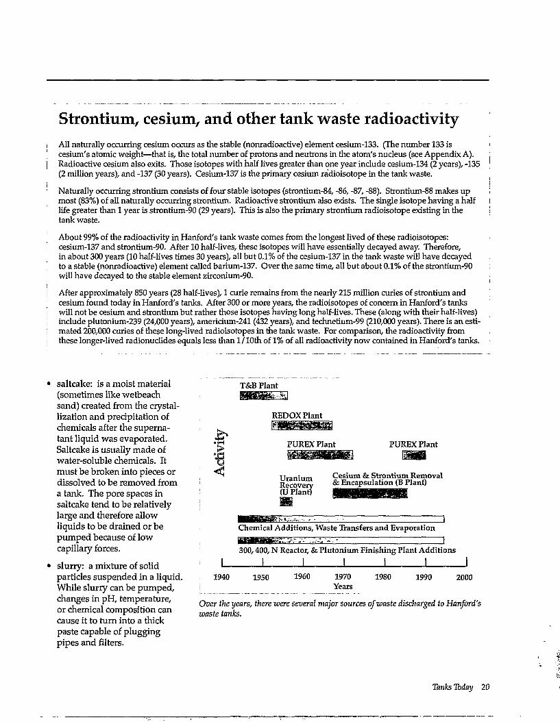
T&B Plant
REDOX Plant
PUREX Plant PUREX Plant
TTraTiiiiin Cesium & Strontium Removal Recovery & Encapsulation (B Plant) (U Plant)
Chemical Additions, Waste Transfers and Evaporation 1
300,400, N Reactor, & Plutonium Finishing Plant Additions 1 I I I I
1940 1950 1960 1970 Years
1980 1990 2000
Over the years, there were several major sources of waste discharged to Hanford's waste tanks.
Tanks Today 20
Organic compounds—complex problems The tank waste contains large amounts of organic compounds. These compounds contain rings or chains of carbon and also include hydrogen with or without oxygen, nitrogen, and other elements (a common example of a complex organic compound is sugar). Some compounds found their way into the waste because they were used in separating out plutonium and uranium. Some waste also contains organic compounds called complexants having simple names like citric acid or scientific names like EDTA (ethylenediaminetetra-acetic acid). These organic compounds and complexants chemically hold onto, or bind to, metals (for example, aluminum or iron) and the waste's radioactive elements. In the 1960s through 1980s, complexants were used at Hanford to remove strontium and cesium from some tank waste.
In the temperatures, pH, and radiation levels found in the tanks today, organic complexants are major contributors to the generation of tank gas (hydrogen, nitrous oxide and ammonia), and therefore the safety problems associated with some tanks. Because complexants are dissolved in the liquids, they are extremely hard to chemically separate from the rest of the tank waste. This complicates the removal of radionuclides and other metals in cleanup.
vapor: gases such as hydrogen, ammonia, nitrous oxide, or other inorganic or organic gases produced by chemical reactions within and radioactive breakdown of organic compounds and water in the tank waste. Most tank vapor space is filled with air circulated in from the outside.
Forming waste layers
When the neutralized waste was discharged from a reprocessing plant, it consisted of liquids and sludges. The liquids contained those compounds (for example, sodium nitrate or ni-
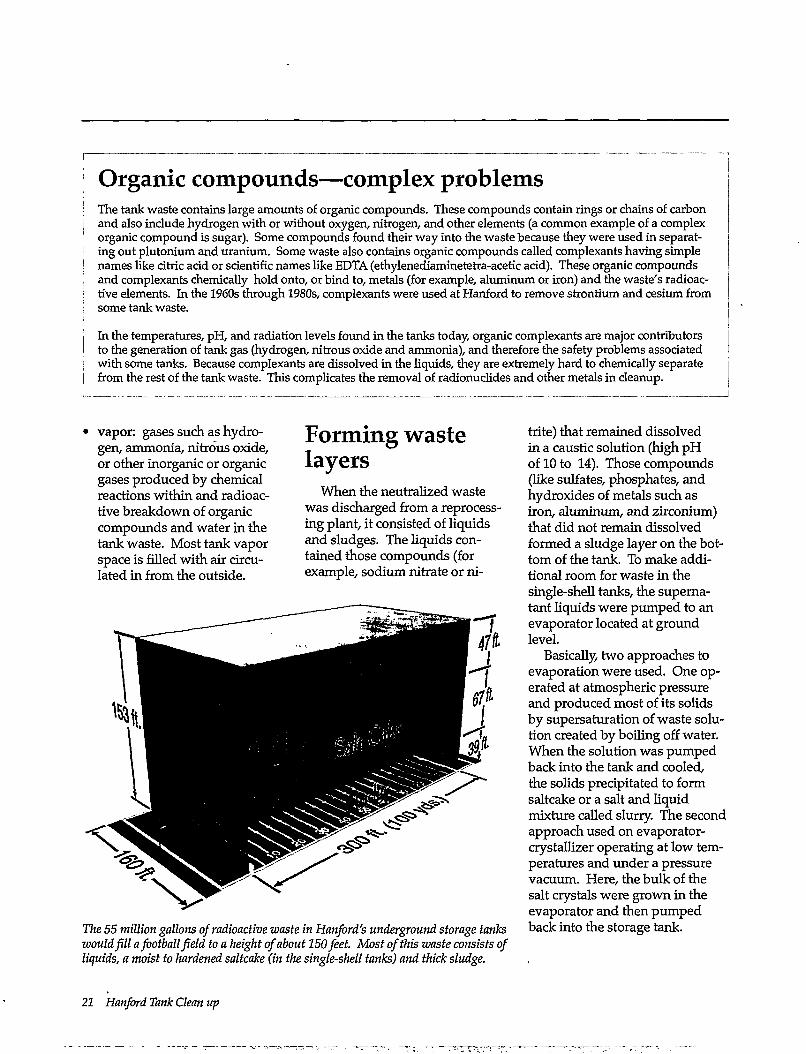
The 55 million gallons of radioactive waste in Hanford's underground storage tanks would fill a football field to a height of about 150 feet. Most of this waste consists of liquids, a moist to hardened saltcake (in the single-shell tanks) and thick sludge.
trite) that remained dissolved in a caustic solution (high p H of 10 to 14). Those compounds (like sulfates, phosphates, and hydroxides of metals such as iron, aluminum, and zirconium) that did not remain dissolved formed a sludge layer on the bottom of the tank. To make additional room for waste in the single-shell tanks, the supernatant liquids were pumped to an evaporator located at ground level.
Basically, two approaches to evaporation were used. One operated at atmospheric pressure and produced most of its solids by supersaturation of waste solution created by boiling off water. When the solution was pumped back into the tank and cooled, the solids precipitated to form saltcake or a salt and liquid mixture called slurry. The second approach used on evaporator-crystallizer operating at low temperatures and under a pressure vacuum. Here, the bulk of the salt crystals were grown in the evaporator and then pumped back into the storage tank.
21 Hanford Tank Clean up
Beginning in the late 1960s, double-shell tanks were built to provide more tank space. The single-shell tank liquids were pumped into the newer, safer double-shell tanks. This left the single-shell tanks containing mostly saltcake and sludge, with some liquids. From then on, the double-shell tanks received supernatant liquids pumped directly from operating reprocessing plants such as the PUREX Plant and supernatant liquids pumped from single-shell tanks. Approximately 75% of the double-shell tank waste consists of waste pumped from single-shell tanks to minimize the potential for leakage.
As of June 1995, the double-shell tanks contained about 20 million gallons of liquids and sludges. Appendix C summarizes the different types of waste found in the double-shell tanks.
A tight squeeze— tank space was limited
Because of the large volume of waste produced, tank space was very limited. Various treatments were used to reduce the amount of liquid. One treatment method caused the precipitation of radioactive chemicals to the bottom portion of the tank, thus making the tank's upper liquid layer less radioactive and less hazardous so it could be disposed in the ground. From 1954 to 1957, radioactive cesium-137 was precipitated out of the solution by adding potassium ferrocyanide
[K4Fe(Cn)6] and nickel sulfate (Ni2S04) to waste piped to the uranium recovery plant. After the cesium settled out, the less radioactive liquid was sent to cribs. A crib is like a shallow buried tile field used to dispose of liquid wastes. Some of the radionuclides in the liquids were adsorbed on the surface of the soil particles. Waste water eventually percolated to the groundwater. With the tank liquids lowered, more plant reprocessing waste could be put in the tanks. Approximately 350 tons of ferrocyanide was added to some tanks in this process.
Tanks Today 22
Since the late 1950s, waste leaks from 67 single-shell tanks have been detected or suspected. This is a key reason why supernatant liquids from the single-shell tanks were pumped into newer and more durable double-shell tanks. With time, more tanks, including double-shell tanks, will exceed their design life expectancy before the waste is removed, processed, and put in some final waste form. Why are leaks a concern? How are leaks detected? Where does the leaked waste go? This section addresses
these and other questions about tank leaks.
Hanf ord's geology and hydrology
Leaks from the single-shell tanks have been a concern because hazardous and radioactive chemicals enter the Hanford soil and potentially groundwater. Sediments underlying the Hanford Site have been deposited in lakes, rivers, and streams over the last 8 million years. The last major sediment
layer was deposited about 13,000 years ago during the last glacial flood.
These sediments have been divided into two major geologic formations or groupings. The uppermost is the Hanford formation, which is 200 to 300 feet thick beneath Hanford's tank farms. This formation is made up of generally very permeable sands and gravels. The lowermost sediment layer is the Ringold Formation. It exhibits different properties because it contains a variety of sediments
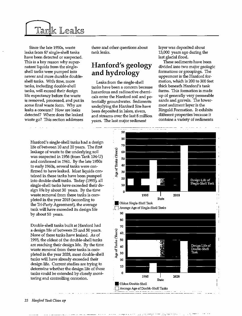
Hanford's single-shell tanks had a design life of between 10 and 20 years. The first leakage of waste to the underlying soil was suspected in 1956 (from Tank 104-U) and confirmed in 1961. By the late 1950s to early 1960s, several tanks were confirmed to have leaked. Most liquids contained in these tanks have been pumped into double-shell tanks. Today (1995), all single-shell tanks have exceeded their design life by about 30 years. By the time waste removal from these tanks is completed in the year 2018 (according to the Tri-Party Agreement), the average tank will have exceeded its design life by about 50 years.
Double-shell tanks built at Hanford had a design life of between 25 and 50 years. None of these tanks have leaked. As of 1995, the oldest of the double-shell tanks are reaching their design life. By the time waste removal from these tanks is completed in the year 2028, most double-shell tanks will have already exceeded their design life. Current studies are trying to determine whether the design life of these tanks could be extended by closely monitoring and controlling corrosion.
Design Life of Single-Shell Tank
i 1995 Date
• Oldest Single-Shell Tank ; []] Average Age of Single-Shell Tanks
90
2018
Date • Oldest Double-Shell
i Q] Average Age of Double-Shell Tanks
23 Hanford Tank Clean up
West Hanford
Formation > a S
CO
a
I
9 0 0 - ,
6 0 0 -
3 0 0 -
0 0 -
Ringold Formation
S -300'
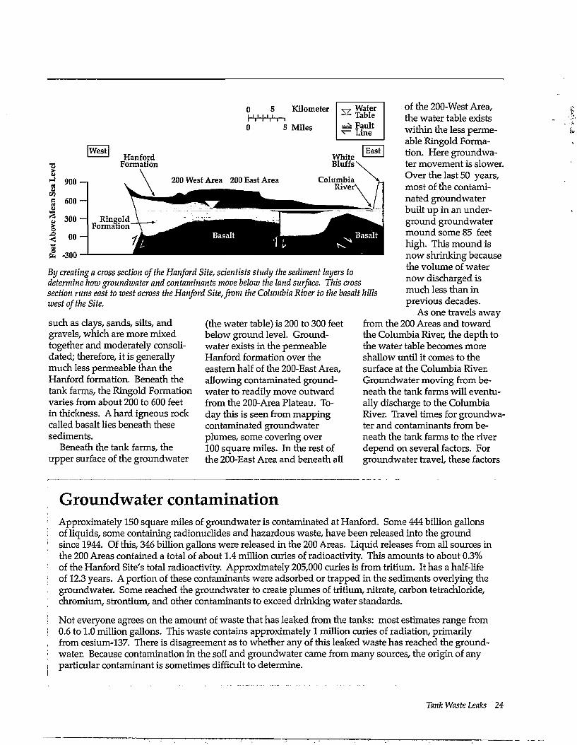
By creating a cross section of the Hanford Site, scientists study the sediment layers to determine how groundwater and contaminants move below the land surface. This cross section runs east to west across the Hanford Site, from the Columbia River to the basalt hills west of the Site.
such as clays, sands, silts, and gravels, which are more mixed together and moderately consolidated; therefore, it is generally much less permeable than the Hanford formation. Beneath the tank farms, the Ringold Formation varies from about 200 to 600 feet in thickness. A hard igneous rock called basalt lies beneath these sediments.
Beneath the tank farms, the upper surface of the groundwater
(the water table) is 200 to 300 feet below ground level. Groundwater exists in the permeable Hanford formation over the eastern half of the 200-East Area, allowing contaminated groundwater to readily move outward from the 200-Area Plateau. Today this is seen from mapping contaminated groundwater plumes, some covering over 100 square miles. In the rest of the 200-East Area and beneath all
ofthe200-WestArea, the water table exists within the less permeable Ringold Formation. Here groundwater movement is slower. Over the last 50 years, most of the contaminated groundwater built up in an underground groundwater mound some 85 feet high. This mound is now shrinking because the volume of water now discharged is much less than in previous decades.
As one travels away from the 200 Areas and toward the Columbia River, the depth to the water table becomes more shallow until it comes to the surface at the Columbia River. Groundwater moving from beneath the tank farms will eventually discharge to the Columbia River. Travel times for groundwater and contaminants from beneath the tank farms to the river depend on several factors. For groundwater travel, these factors
Groundwater contamination Approximately 150 square miles of groundwater is contaminated at Hanford. Some 444 billion gallons of liquids, some containing radionuclides and hazardous waste, have been released into the ground since 1944. Of this, 346 billion gallons were released in the 200 Areas. Liquid releases from all sources in the 200 Areas contained a total of about 1.4 million curies of radioactivity. This amounts to about 0.3% of the Hanford Site's total radioactivity. Approximately 205,000 curies is from tritium. It has a half-life of 12.3 years. A portion of these contaminants were adsorbed or trapped in the sediments overlying the groundwater. Some reached the groundwater to create plumes of tritium, nitrate, carbon tetrachloride, chromium, strontium, and other contaminants to exceed drinking water standards.
Not everyone agrees on the amount of waste that has leaked from the tanks: most estimates range from 0.6 to 1.0 million gallons. This waste contains approximately 1 million curies of radiation, primarily from cesium-137. There is disagreement as to whether any of this leaked waste has reached the groundwater. Because contamination in the soil and groundwater came from many sources, the origin of any particular contaminant is sometimes difficult to determine.
Tank Waste Leaks 24
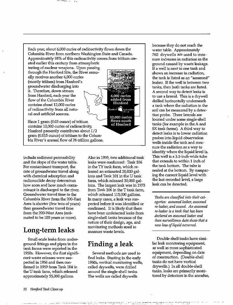
Each year, about 6,000 curies of radioactivity flows down the Columbia River from northern Washington State and Canada. Approximately 98% of this radioactivity comes from tritium created earlier this century from atmospheric testing of nuclear weapons. Upon passing through the Hanf ord Site, the River annually receives another 6,000 curies (mostly tritium) from Hartford's groundwater discharging into it. Therefore, down stream from Hanford, each year the flow of the Columbia River contains about 12,000 curies of radioactivity from all natural and artificial sources.
Since 1 gram (0.03 ounce) of tritium contains 10,000 curies of radioactivity, Hanford presently contributes about 1/2 gram (0.015 ounce) of tritium to the Columbia River's annual flow of 28 trillion gallons.
include sediment permeability and the slope of the water table. For contaminant transport, the rate of groundwater travel along with chemical adsorption and radionuclide decay determines how soon and how much contaminant is discharged to the river. Groundwater travel time to the Columbia River from the 200-East Area is shorter (few tens of years) than groundwater travel time from the 200-West Area (estimated to be 100 years or more).
Long-term leaks Small-scale leaks from under
ground fittings and pipes in the tank farms were reported in the 1950s. However, the first significant waste releases were suspected in 1956 and then confirmed in 1959 from Tank 104 in the U tank farm, which released approximately 55,000 gallons.
Also in 1959, two additional tank leaks were confirmed: Tank 106 in the TY tank farm, which released an estimated 20,000 gallons and Tank 101 in the U tank farm, which released 30,000 gallons. The largest leak was in 1973 from Tank 106 in the T tank farm, which released 115,000 gallons. In many cases, a leak was suspected before it was identified or confirmed. It is likely that there have been undetected leaks from single-shell tanks because of the nature of their design, age, and monitoring methods used to measure waste levels.
Finding a leak Several methods are used to
find leaks. Starting in the early 1960s, vertical monitoring wells, called drywells, were drilled around the single-shell tanks. The wells are called drywells
because they do not reach the water table. Approximately 760 drywells are used to measure increases in radiation in the ground caused by waste leakage. If a well is next to one tank and shows an increase in radiation, the tank is listed as an "assumed" leaker. If the well is between two tanks, then both tanks are listed. A second way to detect leaks is to use a lateral. This is a drywell drilled horizontally underneath a tank where the radiation in the soil can be measured by a detection probe. Three laterals are located under some single-shell tanks (for example in the A and SX tank farms). A third way to detect leaks is to lower radiation probes into liquid observation wells inside the tank and measure the radiation as a way to identify where the liquid level is. This well is a 3.5-inch-wide tube that extends to within 1 inch of the tank bottom. The tube is sealed at the bottom. By comparing the current liquid level with the last recorded level, a large leak can be detected.
Tanks are classified into their categories: assumed leaker, assumed re-leaker, and sound. An assumed re-leaker is a tank that has been declared an assumed leaker and then surveillance data show that a new loss of liquid occurred.
Double-shell tanks have similar leak monitoring equipment, as well as more sophisticated equipment, depending on date of construction. (Double-shell tanks do not have vertical drywells.) In all double-shell tanks, leaks are primarily monitored by detectors in the annulus,
25 Hanford Tank Clean up
200 West Area T-Tank Farm
TY-Tank Farm
TX-Tank Farm
U-Tank Farm
S-TankFarm
SX-Tank Farm
200 East Area
BY-Tank Farm
Legend (g) Leaker or
suspected leaker O Non-leaker
B-Tank Farm
C-Tank Farm
Bs AY-TankFann
B
PUREX Plant
AW-TankFarm ^ ^ U 1 1
AN-Tank Farm
AZ-Tank Farm
AX-Tank Farm
A-Tank Farm
AP-Tank Farm
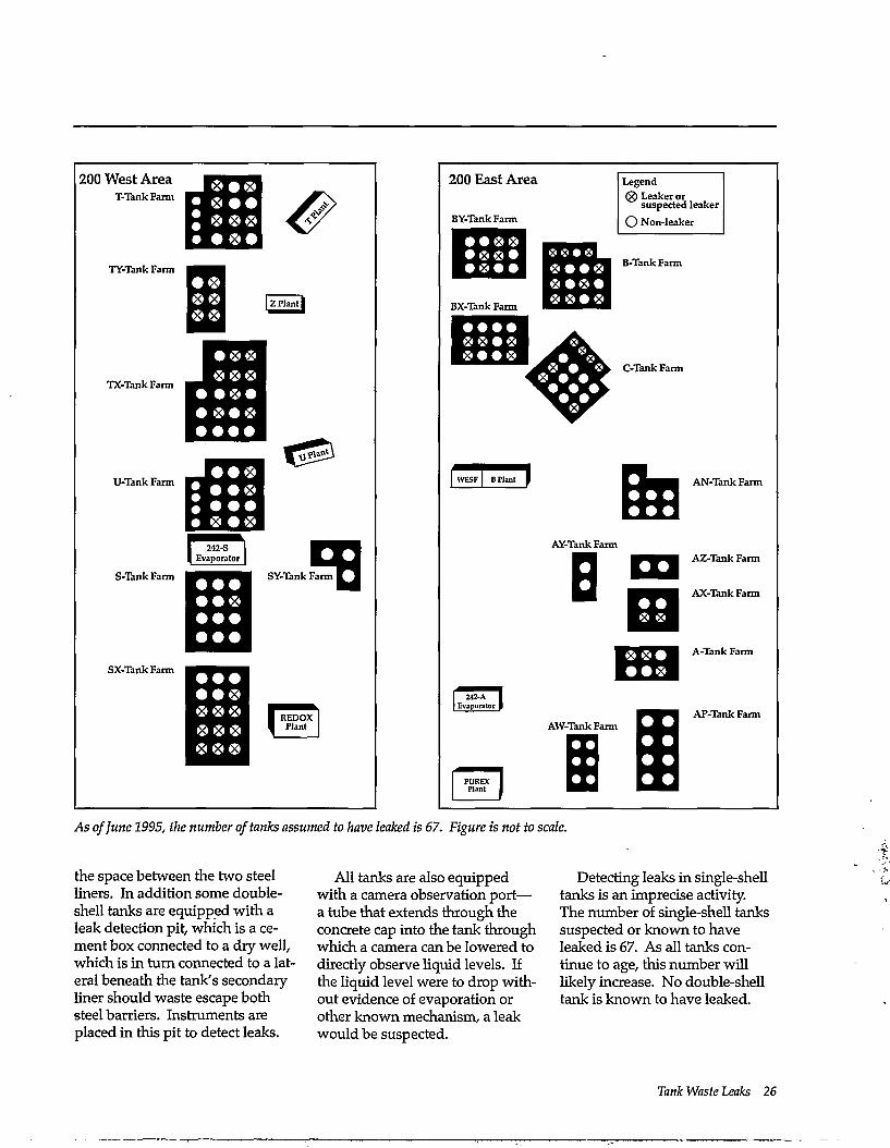
As of June 1995, the number of tanks assumed to have leaked is 67. Figure is not to scale.
the space between the two steel liners. In addition some double-shell tanks are equipped with a leak detection pit, which is a cement box connected to a dry well, which is in turn connected to a lateral beneath the tank's secondary liner should waste escape both steel barriers. Instruments are placed in this pit to detect leaks.
All tanks are also equipped with a camera observation port— a tube that extends through the concrete cap into the tank through which a camera can be lowered to directly observe liquid levels. If the liquid level were to drop without evidence of evaporation or other known mechanism, a leak would be suspected.
Detecting leaks in single-shell tanks is an imprecise activity. The number of single-shell tanks suspected or known to have leaked is 67. As all tanks continue to age, this number will likely increase. No double-shell tank is known to have leaked.
Tank Waste Leaks 26
At what price cleanup? Cleanup means different things to different people. To some, the Hanford Site will only be clean when all areas have been returned to pristine (pre-Hanford) conditions. To others, the Site will be clean when most areas are available for industrial or residential use. Others would settle for having certain areas be "sacrifice" zones, in which hazardous chemicals and radioactive materials could be stored indefinitely. Many interpretations and expectations exist.
Each definition of cleanup will impact cleanup costs, schedules, human health risk, and technology needs. Some existing technology is likely suitable for beginning cleanup of Hanford's tank waste—for example, the high-level waste vitrification technology found in the Defense Waste Reprocessing Facility (DWPF) at the Savannah River Site in South Carolina. However, because of the greater complexities of Hanford tank wastes many existing technologies must be adapted (for example, adapting robotic systems to remove tank waste through the tank's risers). Some problems may only be cost effectively handled by technologies still under development, such as high-efficiency methods to separate radionuclides from chemical waste.
Current estimates for Hanford cleanup range from a few tens of billions to a few hundred billion dollars. The estimates vary because much remains unknown about cleanup, such as
• What level of cleanup is necessary?
• What will the land be used for after cleanup?
• What will the final waste forms be?
• What human health risks do we face? Today? During cleanup? Tomorrow?
• What cleanup approaches will be used?
• How well can existing technologies accomplish cleanup?
• How much could improved technologies reduce cost?
Cleanup money will be allocated by Congress. Money spent on cleanup is money that cannot be spent for other national problems. There is a growing need to demonstrate progress and risk reduction for the money spent.
Reducing leaks To lessen the chance of waste
leaking to the soil from single-shell tanks, the amount of liquid in the tanks was reduced by evaporation and by pumping it to double-shell tanks. Only the drainable liquid is pumped from the tank—not all can be pumped because some is trapped in the
saltcake and sludge. Pumping was temporarily stopped on several tanks because of safety concerns about allowing the waste to become dry waste. It is estimated that approximately 6 million gallons of pumpable liquid remain in single-shell tanks.
The detection and prevention of leaks will become increasingly important as tank cleanup
proceeds. This is because the removal of waste solids (saltcake) and nonpumpable sludges may require the addition of fluids to the tanks. This increases the potential for leaks if there are cracks in the tank walls. With time, even the double-shell tanks will exceed their life expectancy and the potential for their leaking increases.
27 Hanford Tank Clean up
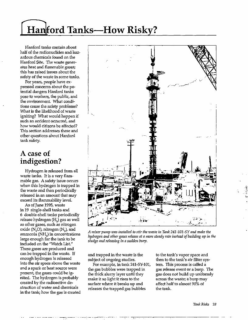
A mixer pump was installed to stir the waste in Tank 241-101-SY and make the hydrogen and other gases release at a more steady rate instead of building up in the sludge and releasing in a sudden burp.
Hanford tanks contain about half of the radionuclides and hazardous chemicals found on the Hanford Site. The waste generates heat and flammable gases; this has raised issues about the safety of the waste in some tanks.
For years, people have expressed concerns about the potential dangers Hanford tanks pose to workers, the public, and the environment. What conditions cause the safety problems? What is the likelihood of waste igniting? What would happen if such an accident occurred, and how would citizens be affected? This section addresses these and other questions about Hanford tank safety.
A case of indigestion?
Hydrogen is released from all waste tanks. It is a very flammable gas. A safety issue occurs when this hydrogen is trapped in the waste and then periodically released in an amount that may exceed its flammability level.
As of June 1995, waste in 19 single-shell tanks and 6 double-shell tanks periodically release hydrogen (HJ gas as well as other gases, such as nitrogen oxide (N20), nitrogen (N2), and ammonia (NHj) in concentrations large enough for the tank to be included on the "Watch List." These gases are produced and can be trapped in the waste. If enough hydrogen is released into the air space above the waste and a spark or heat source were present, the gases could be ignited. The hydrogen is probably created by the radioactive destruction of water and chemicals in the tank; how the gas is created
and trapped in the waste is the subject of ongoing studies.
For example, in tank 241-SY-lOl, the gas bubbles were trapped in the thick slurry layer until they make it so light it rises to the surface where it breaks up and releases the trapped gas bubbles
to the tank's vapor space and then to the tank's air filter system. This process is called a gas release event or a burp. The gas does not build up uniformly across the waste; a burp may affect half to almost 90% of the tank.
Tank Risks 28
Chronology of Hanf ord tank risk evaluations Following is a chronology of key evaluations ofHanford tank risks.
• A1984 report by the Pacific Northwest Laboratory discusses a "highly improbable, worst-case" Hartford tank explosion that would be equivalent to a 36-ton TNT blast.
• DOE's 1987 Environmental Impact Statement (EIS) for Hanford defense waste analyzes what would happen if a tank exploded during cleanup activities. The subsequent public radiation dose would be about the same as that from natural and man-made radiation sources. (That amount is about 365 millirem per year; see the box later in this section called, "A radiation dose perspective.")
• From 1984 through 1992, tank risks, focusing primarily on explosions, are evaluated by DOE, DOE-sponsored independent groups, the States of Washington and Oregon, the U.S. Defense Nuclear Facilities Safety Board, and other groups. These studies say that the probability of an explosion is low, very low, or highly unlikely. Two main reasons are given. One is that a chemical that could cause an explosion—ferrocyanide—is too diluted to cause an explosion. The other reason is that the highest temperatures (135 to 141 °F) measured in Hanford tanks that contain ferrocyanide were lower than the temperatures at which chemical reactions may occur.
• A1990 U.S. Government Accounting Office (GAO) report reviews the studies to date. The GAO concludes that the probability of an explosion may be low, but not enough is known about the waste to rule out the possibility of a spontaneous explosion. Moreover, the report says that the public radiation dose from a tank explosion could be much higher than that estimated in the 1987 EIS. The GAO report says inhaling small particles of tank waste from an explosion could give a 7.3-rem radiation dose to a person over his/her lifetime. According to the U.S. Nuclear Regulatory Commission, this amount could cause one cancer death out of every 160 people who received this dose. (In a group of this size, from 32 to 40 cancer deaths typically occur over time from other causes.)
• A1994 study by Los Alamos National Laboratory and PLG, Inc. investigates the risks from Tank 101-SY. The "highest contributor to risk" is described as a hydrogen "burp" that is ignited by a spark, causing a fire and releasing tank contents to the environment. The highest dose to a worker at about 400 feet from the tank from this kind of accident is estimated at 37.4 rem Effective Dose Equivalent. The highest dose to a member of the public living at the boundary of the Hanford Site is estimated at 0.134 rem Effective Dose Equivalent. These are "lifetime" estimates, which include the dose received over 50 years following the accident. This is because radioactive materials taken into the body, such as through breathing, continue to irradiate a person as long as they remain in the body. The chances of this accident occurring are estimated at up to 4 in 1,000. The report also says that tank chemicals from such an accident could take anywhere from 200 to 2,000 years to reach the Columbia River. By that time, the report says, they would have been reduced to concentrations below those allowed by federal drinking water standards.
A millirem is one-thousa?idth of a rem. A rem is a scientific term that measures the radiation exposure to people. The term, "Effective Dose Equivalent" is an estimate of the total risk of potential health effects from radiation exposure.
• In 1994, Westinghouse Hanford Company revises its hazards assessment for the tanks. The report looks at a variety of risks such as hydrogen burning, explosions, tank filter failure, and chemical releases. The report estimates radiation doses to workers and the public from a worst-case hydrogen explosion and burn. The estimated doses are up to 100,000 rem for a worker near the tank and a lifetime dose of 64 rem to a member of the public near the Site. These worst-case situations assume that air currents carry all the contaminant particles directly to people, and people are assumed to take no protective actions for the entire time tank contents are being released.
• DOE's 1994 Draft Environmental Impact Statement on Safe Interim Storage of Hanford Tank Wastes investigates accidents involving Tanks 101-SY and 103-SY that could occur now and those that could happen if some tank contents were pumped into new tanks. The accidents investigated are a pressurized spray leak, a tank leak, and a flammable gas burn. The report estimates the chances of any of these accidents happening at approximately 5 in 10,000. The highest radiation dose to the public is estimated at 130 person-rem. Person-rem is the total dose to all individuals in a group, in this case, all people living within 50 miles of the tanks. This dose could result in less than one (0.07) additional cancer death in that group of people.
29 Hanford Tank Clean up
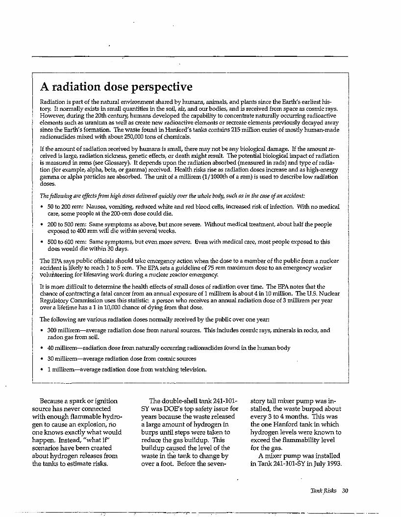
A radiation dose perspective Radiation is part of the natural environment shared by humans, animals, and plants since the Earth's earliest history. It normally exists in small quantities in the soil, air, and our bodies, and is received from space as cosmic rays. However, during the 20th century, humans developed the capability to concentrate naturally occurring radioactive elements such as uranium as well as create new radioactive elements or recreate elements previously decayed away since the Earth's formation. The waste found in Hanford's tanks contains 215 million curies of mostly human-made radionuclides mixed with about 250,000 tons of chemicals.
If the amount of radiation received by humans is small, there may not be any biological damage. If the amount received is large, radiation sickness, generic effects, or death might result. The potential biological impact of radiation is measured in rems (see Glossary). It depends upon the radiation absorbed (measured in rads) and type of radiation (for example, alpha, beta, or gamma) received. Health risks rise as radiation doses increase and as high-energy gamma or alpha particles are absorbed. The unit of a millirem (1/1000th of a rem) is used to describe low radiation doses.
The following are effects from high doses delivered quickly over the whole body, such as in the case of an accident:
• 50 to 200 rem: Nausea, vomiting, reduced white and red blood cells, increased risk of infection. With no medical care, some people at the 200-rem dose could die.
• 200 to 500 rem: Same symptoms as above, but more severe. Without medical treatment, about half the people exposed to 400 rem will die within several weeks.
• 500 to 600 rem: Same symptoms, but even more severe. Even with medical care, most people exposed to this does would die within 30 days.
The EPA says public officials should take emergency action when the dose to a member of the public from a nuclear accident is likely to reach 1 to 5 rem. The EPA sets a guideline of 75 rem maximum dose to an emergency worker volunteering for lifesaving work during a nuclear reactor emergency.
It is more difficult to determine the health effects of small doses of radiation over time. The EPA notes that the chance of contracting a fatal cancer from an annual exposure of 1 millirem is about 4 in 10 million. The U.S. Nuclear Regulatory Commission uses this statistic: a person who receives an annual radiation dose of 3 millirem per year over a lifetime has a 1 in 10,000 chance of dying from that dose.
The following are various radiation doses normally received by the public over one year:
• 300 millirem—average radiation dose from natural sources. This includes cosmic rays, minerals in rocks, and radon gas from soil.
• 40 millirem—radiation dose from naturally occurring radionuclides found in the human body
• 30 millirem—average radiation dose from cosmic sources
• 1 millirem—average radiation dose from watching television.
Because a spark or ignition source has never connected with enough flammable hydrogen to cause an explosion, no one knows exactly what would happen. Instead, "what if" scenarios have been created about hydrogen releases from the tanks to estimate risks.
The double-sheU tank 241-101-SY was DOE's top safety issue for years because the waste released a large amount of hydrogen in burps until steps were taken to reduce the gas buildup. This buildup caused the level of the waste in the tank to change by over a foot. Before the seven-
story tall mixer pump was installed, the waste burped about every 3 to 4 months. This was the one Hanford tank in which hydrogen levels were known to exceed the flammability level for the gas.
A mixer pump was installed in Tank 241-101-SY in July 1993.
Tank Risks 30
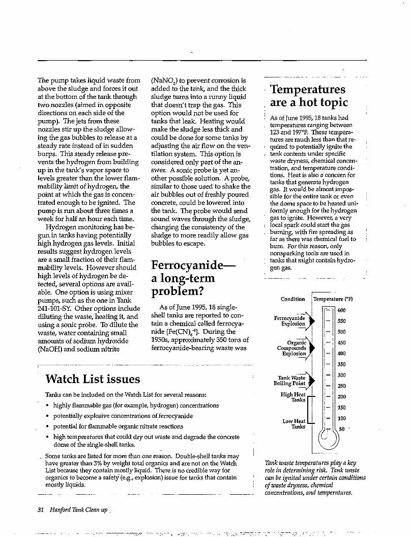
The pump takes liquid waste from above the sludge and forces it out at the bottom of the tank through two nozzles (aimed in opposite directions on each side of the pump). The jets from these nozzles stir up the sludge allowing the gas bubbles to release at a steady rate instead of in sudden burps. This steady release prevents the hydrogen from building up in the tank's vapor space to levels greater than the lower flam-mability limit of hydrogen, the point at which the gas is concentrated enough to be ignited. The pump is run about three times a week for half an hour each time.
Hydrogen monitoring has begun in tanks having potentially high hydrogen gas levels. Initial results suggest hydrogen levels are a small fraction of their flam-mability levels. However should high levels of hydrogen be detected, several options are available. One option is using mixer pumps, such as the one in Tank 241-101-SY. Other options include diluting the waste, heating it, and using a sonic probe. To dilute the waste, water containing small amounts of sodium hydroxide (NaOH) and sodium nitrite
(NaNO z) to prevent corrosion is added to the tank, and the thick sludge turns into a runny liquid that doesn't trap the gas. This option would not be used for tanks that leak. Heating would make the sludge less thick and could be done for some tanks by adjusting the air flow on the ventilation system. This option is considered only part of the answer. A sonic probe is yet another possible solution. A probe, similar to those used to shake the air bubbles out of freshly poured concrete, could be lowered into the tank. The probe would send sound waves through the sludge, changing the consistency of the sludge to more readily allow gas bubbles to escape.
Ferrocyanide— a long-term problem?
As of June 1995,18 single-shell tanks are reported to contain a chemical called ferrocyanide [Fe(CN)6'4]. During the 1950s, approximately 350 tons of ferrocyanide-bearing waste was
Watch List issues Tanks can be included on the Watch List for several reasons: • highly flammable gas (for example, hydrogen) concentrations • potentially explosive concentrations of ferrocyanide • potential for flammable organic nitrate reactions • high temperatures that could dry out waste and degrade the concrete
dome of the single-shell tanks.
Some tanks are listed for more than one reason. Double-shell tanks may have greater than 3% by weight total organics and are not on the Watch List because they contain mostly liquid. There is no credible way for organics to become a safety (e.g., explosion) issue for tanks that contain mostly liquids.
Temperatures are a hot topic As of June 1995,18 tanks had temperatures ranging between 123 and 197°E These temperatures are much less than that required to potentially ignite the tank contents under specific waste dryness, chemical concentration, and temperature conditions. Heat is also a concern for tanks that generate hydrogen gas. It would be almost impossible for the entire tank or even the dome space to be heated uniformly enough for the hydrogen gas to ignite. However, a very local spark could start the gas burning, with fire spreading as far as there was chemical fuel to burn. For this reason, only nonsparking tools are used in tanks that might contain hydrogen gas.
Condition
Ferrocyanide ^ Explosion W
Temperature (°F) 600
Tank Waste Boiling Point
High Heat Tanks
Low Heat l _ Tanks
550 500 450 400 350 300 250 200 150 100 50
Tank waste temperatures play a key role in determining risk. Tank waste can be ignited under certain conditions of waste dryness, chemical concentrations, and temperatures.
31 Hanford Tank Clean up
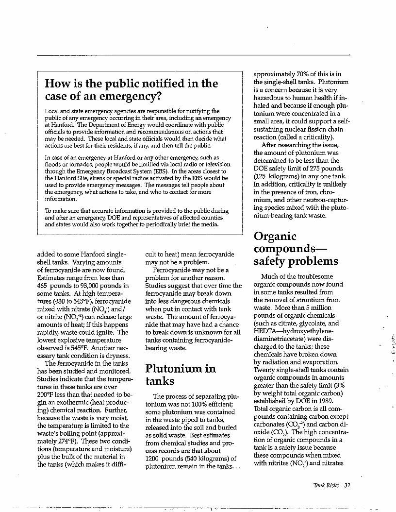
How is the public notified in the case of an emergency? Local and state emergency agencies are responsible for notifying the public of any emergency occurring in their area, including an emergency at Hanford. The Department of Energy would coordinate with public officials to provide information and recommendations on actions that may be needed. These local and state officials would then decide what actions are best for their residents, if any, and then tell the public.
In case of an emergency at Hanford or any other emergency, such as floods or tornados, people would be notified via local radio or television through the Emergency Broadcast System (EBS). In the areas closest to the Hanford Site, sirens or special radios activated by the EBS would be used to provide emergency messages. The messages tell people about the emergency, what actions to take, and who to contact for more information.
To make sure that accurate information is provided to the public during and after an emergency, DOE and representatives of affected counties and states would also work together to periodically brief the media.
added to some Hanford single-shell tanks. Varying amounts of ferrocyanide are now found. Estimates range from less than 465 pounds to 93,000 pounds in some tanks. At high temperatures (430 to 545°F), ferrocyanide mixed with nitrate (N0 3 ' ) and/ or nitrite (N0 2" 2) can release large amounts of heat; if this happens rapidly, waste could ignite. The lowest explosive temperature observed is 545°F. Another necessary tank condition is dryness.
The ferrocyanide in the tanks has been studied and monitored. Studies indicate that the temperatures in these tanks are over 200°F less than that needed to begin an exothermic (heat producing) chemical reaction. Further, because the waste is very moist, the temperature is limited to the waste's boiling point (approximately 274°F). These two conditions (temperature and moisture) plus the bulk of the material in the tanks (which makes it diffi
cult to heat) mean ferrocyanide may not be a problem.
Ferrocyanide may not be a problem for another reason. Studies suggest that over time the ferrocyanide may break down into less dangerous chemicals when put in contact with tank waste. The amount of ferrocyanide that may have had a chance to break down is unknown for all tanks containing ferrocyanide-bearing waste.
Plutonium in tanks
The process of separating plu-tonium was not 100% efficient; some plutonium was contained in the waste piped to tanks, released into the soil and buried as solid waste. Best estimates from chemical studies and process records are that about 1200 pounds (540 kilograms) of plutonium remain in the tanks . . .
approximately 70% of this is in the single-shell tanks. Plutonium is a concern because it is very hazardous to human health if inhaled and because if enough plutonium were concentrated in a small area, it could support a self-sustaining nuclear fission chain reaction (called a criticality).
After researching the issue, the amount of plutonium was determined to be less than the DOE safety limit of 275 pounds (125 kilograms) in any one tank. In addition, criticality is unlikely in the presence of iron, chromium, and other neutron-capturing species mixed with the pluto-nium-bearing tank waste.
Organic compounds— safety problems
Much of the troublesome organic compounds now found in some tanks resulted from the removal of strontium from waste. More than 5 million pounds of organic chemicals (such as citrate, glycolate, and HDEDTA—hydroxyethylene-diaminetriacetate) were discharged to the tanks; these chemicals have broken down by radiation and evaporation. Twenty single-shell tanks contain organic compounds in amounts greater than the safety limit (3% by weight total organic carbon) established by DOE in 1989. Total organic carbon is all compounds containing carbon except carbonates (C0 3
2 ) and carbon dioxide (C0 2). The high concentration of organic compounds in a tank is a safety issue because these compounds when mixed with nitrites (NOz") and nitrates
Tank Risks 32
(N03") at temperature greater than about 430°F can ignite. The situation is similar to wood in a fireplace: until the temperature is raised high enough using a match, for instance, the fire is not sustainable. Currently, these tanks contain a lot of liquids and the temperatures range from about 60°F to~200°F, 230°F below the temperature required for an exothermic chemical reaction. Several double-shell tanks contain waste with greater than 3% by weight total organic carbon and as high as 10%, but these tanks contain primarily liquids and are not considered a risk because the waste is mostly liquid.
Activities that could cause heat to increase to levels above the defined safety levels are limited at the tank. Tank samples
are being analyzed to determine whether chemicals or concentrations of organic material are present and, if present, whether tank conditions (such as moisture) can prevent an explosive chemical reaction between the organic compounds and nitrate.
Organic compounds— waste treatment problems
Organic compounds chemically bind onto radioactive and nonradioactive metals (for example, strontium or aluminum). This is especially true for the more complex organics used in
the solvent extraction process or for the recovery of uranium, cesium, and strontium from tank waste. This chemical bonding makes it difficult to remove radionuclides from the rest of the tanks waste so they can be separated into a waste stream for vitrification. Research is underway in how to breakdown these complex organics.
33 Hanford Tank Clean up
What's in the Tanks? To safely pretreat, separate,
and store tank waste until it can be processed into a form that will remain stable and isolated over the years, the types, concentrations, and forms of chemicals and chemical compounds that are in the tanks must be understand. Why do we need to know? How do we find out what is in the tanks? What can waste samples tell us? This section addresses these and other questions about characterizing tank waste.
Getting to know the waste
One of the-major debates in waste characterization evolves around the issue of how much characterization is enough to proceed. There is no single answer. Rather there are multiple answers because each tank safety, waste handling, or treatment activity has its own characterization needs. However, what is generally agreed to is that characterization data are needed to determine if the waste is stored safely, resolve safety issues, and develop chemical processes and design facilities to treat and dispose of the waste.
- To be effective in treating, storing and disposing the waste, the chemistry of the waste must be understood. To understand how the waste will behave as it is retrieved and processed, data are needed on the physical properties of the waste, including temperature, moisture content, solid particle density, and fluid dynamics (stickiness). Knowing the type
and distribution of chemical compounds in the waste is also critical, because these influence how tightly radionuclides and other metals are chemically bound and how waste fluid flow through pipes will change under varying temperature and pH conditions. (Under various conditions, waste can either flow like water or congeal into a solid to clog pipes.) The type and distribution of chemical compounds also greatly affects what treatment and separation technologies will be effective, because some chemical compounds such as carbonates can be easily dissolved using acids and their contents leached while other compounds such as hydroxides, oxides or aluminates are much less leachable. Also, the presence of some metals such as chromium and aluminum in the final stream of waste going to,a processing plant to be made into a waste form can interfere with glass formation and durability.
Complex history, complex waste
Hanford's tank waste is complex because the nuclear fuel reprocessing history was complex, in many ways more complex than other DOE or international sites because:
• Multiple irradiated fuel reprocessing practices were used.
• Acidic waste from the reprocessing plants was made caustic by adding sodium hydroxide (NaOH). This caused some
of the waste to form solid particles as well as precipitate to the bottom of the tanks. Some chemical compounds (such as iron hydroxide and aluminum hydroxide) and their bonded radionuclides such as pluto-nium settled to the bottom of the tank while cesium normally remained in solution.
• Evaporation of some tank liquids led to the formation of hard saltcakes and thick slurries. This also contributed to an uneven distribution of chemical compounds and radionuclides.
• Ferrocyanides were added to some tanks to precipitate (settle to the bottom of the tank) ce-sium-137 and strontium-90 so that less-radioactive liquids could be discharged to the soil.
• Waste was transferred between tanks and between tank farms (sometimes few records were kept).
• The tanks received several sources of waste having diverse chemical characteristics besides that discharged from the reprocessing plants. These included waste from processing campaigns to remove uranium, strontium, and cesium from the tanks (see Appendix C).
• In early attempts to stabilize some tank wastes in place, cement or diatomaceous earth was added to soak up liquids.
This history makes it more difficult and costly to determine what the waste contents are
Tank Characterization 34
Waste characterization: key questions Deterrnining what is in the waste and how it will affect the ability to treat, store, and dispose of it, is an ongoing process, with many scientists and engineers offering different opinions. Some of the key characterization issues involve:
• collecting samples for analyses that adequately represent the tank's waste contents (solids, liquids, sludges, and slurries)
• lowering the cost of waste sample analyses by improving analytical techniques
• when possible, conducting chemical, physical, and radiological analyses inside the tank instead of a laboratory to reduce the cost of laboratory analyses and lower the production of new (called secondary) wastes
• using in-tank surface and subsurface scanning and imaging techniques to remotely map the major physical properties of a tank's waste
• characterizing waste for those key element and chemical compounds that will affect waste treatment, processing, and final waste form development. These includes the aluminum, phosphorus, chromium, and strontium content of the waste and their chemical nature—how they are bound, for example, with the nitrates, hydroxides, oxides, and phosphates contained in the waste.
• assessing quality assurance and data reporting requirements to ensure they add value rather than just cost.
because any one waste sample is unlikely to be representative of the contents of a single tank or of a single waste type distributed between several tanks. Hartford has 177 tanks. Multiple waste samples may be needed from each tank and waste layer (sludge, slurry, and supernatant liquids). Also pound-size quantities of waste will be needed to research waste treatment options. Otherwise, the waste treatment and disposal technologies used must be designed to safely handle a wide range of partially known chemical and radiological waste.
Getting in and getting it out
Several methods of waste sampling have been developed. Samples may be taken by core drilling, grab sampling, auger use, or various types of vapor sampling. Sampling of any kind is difficult not only because the openings in the tanks (called risers) are limited in number, size, and location but also because the waste is radioactive, requiring special precautions for personnel -and handling of equipment and samples.
Core sampling is used to obtain solid or supernatant waste samples. The sampler's drill bit is either pushed (push-mode sampling) or rotated (rotary-core sampling) through the waste. Each sampler is approximately 1 inch in diameter and 20 inches long. Only the area entered into by the sampler is sampled. Rotary-core sampling is mainly used to sample the hard saltcake; however, it may be used to sample supernatant liquid or soft sludge. Push-mode sampling, on the other hand," is used to sample only the supernatant liquid and soft sludge.
35 Hanford Tank Clean up
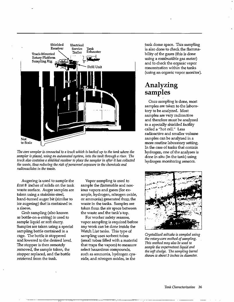
Shielded Electrical Receiver Service Tank
The core sampler is connected to a truck which is backed up to the tank where the sampler is placed, using an automated system, into the tank through a riser. The truck also contains a shielded receiver to place the sampler in after it has collected the waste, thus reducing the risk of personnel exposure to the chemicals and radionuclides in the waste.
Augering is used to sample the first 8 inches of solids on the tank waste surface. Auger samples are taken using a stainless-steel, hand-turned auger bit (similar to ice augering) that is contained in a sleeve.
Grab sampling (also known as bottle-on-a-string) is used to sample liquid or soft slurry. Samples are taken using a special sampling bottle contained in a cage. The bottle is stoppered and lowered to the desired level. The stopper is then remotely removed, the sample taken, the stopper replaced, and the bottle retrieved from the tank.
Vapor sampling is used to sample the flammable and noxious vapors and gases (for example, hydrogen, nitrogen oxide, or ammonia) generated from the waste in the tanks. Samples are taken from the air space between the waste and the tank's top.
For worker safety reasons, vapor sampling is required before any work can be done inside the Watch List tanks. This type of sampling uses sorbent tubes (small tubes filled with a material that traps the vapors) to measure select hazardous compounds, such as ammonia, hydrogen cyanide, and nitrogen oxides, in the
tank dome space. This sampling is also done to check the flamma-bility of the gases (this is done using a combustible gas meter) and to check the organic vapor concentration within the tanks (using an organic vapor monitor).
Analyzing samples
Once sampling is done, most samples are taken to the laboratory to be analyzed. Most samples are very radioactive and therefore must be analyzed in a specially shielded facility called a "hot cell." Less radioactive and smaller volume samples can be analyzed in a more routine laboratory setting. In the case of tanks that contain hydrogen, one of the analyses is done in situ (in the tank) using hydrogen monitoring sensors.
Crystallized saltcake is sampled using the rotary-core method of sampling. This method may also be used to sample the supernatant liquid and the soft sludge. The sampling barrel shown is about 3 inches in diameter.
Tank Characterization 36
Waste samples are routinely analyzed using different technologies. For example, inductively coupled plasma (ICP) or atomic absorption is used to determine what metallic elements are present. Other technologies include ion chromatography, gamma energy analysis, alpha energy analysis, and gas chroma-tography-mass spectrometry (GC/MS). As needs are identified for cleanup, new analysis technologies may be developed, or existing ones modified. For example, more rapid analysis techniques are needed to assess the changing physical and chemical conditions of the waste during waste treatment and processing.
One of the main concerns when analyzing waste samples is personnel exposure to radiation. High-level waste is analyzed in hot cells (shielded laboratory rooms) using remote robotics "arms" to handle the samples. Samples with lower
levels of radiation may be analyzed in smaller shielded containers such as gloveboxes or under ventilation hoods. Because of these precautions, analyses take longer compared to nonradioactive analyses and operations in other industries.
Getting to knowledge
Sample characterization can be expensive. To characterize one core sample, the cost, which includes the cost of obtaining the sample, can average a few hundred thousand dollars. This cost is due to a combination of factors, including:
• worker protection precautions
• quality assurance and data reporting requirements
• sample collection, analysis, and storage methods
• nonroutine analyses.
Is all tank waste highly radioactive?
This is a critical question because the answer can impact the cost, schedule, and cleanup approach used for treating and disposing of Hanford's tank waste.
In most countries, the definition of high-level and low-level radioactive waste is determined by levels of radioactivity. However, in the United States waste categories are based upon waste sources rather than radioactivity. For example, all waste from the first cycle of solvent extraction in Hanford's REDOX and PUREX Plants could be classified as high-level waste based upon definitions contained DOE Order 5820.2A. That order states high-level waste is:
"The highly radioactive material that results from the reprocessing of spent nuclear
What is low-level radioactive waste? Low-level radioactive waste is waste not classified as high-level radioactive waste, transuranic waste, spent nuclear fuel, or certain uranium or thorium containing waste. Commercially generated low-level waste comes from nuclear power plants, hospitals, research facilities, and radiopharmaceutical manufactures. DOE examples include contaminated materials such as clothing, air filters, paint residues, and soils.
For commercially generated low-level waste, the Nuclear Regulatory Commission has defined four disposal categories requiring increasingly stringent waste handling, confinement, shipment, and monitoring: Classes A, B, C, and Greater-Than-Class-C. Class A, B, and C waste is generally suitable for insitu or near-surface disposal. States are responsible for the disposal of these wastes. Disposal of Greater-Than-Class-C waste is the responsibility of the federal government. It generally requires more rigorous disposal such as in a geologic repository.
37 Hanford Tank Clean up
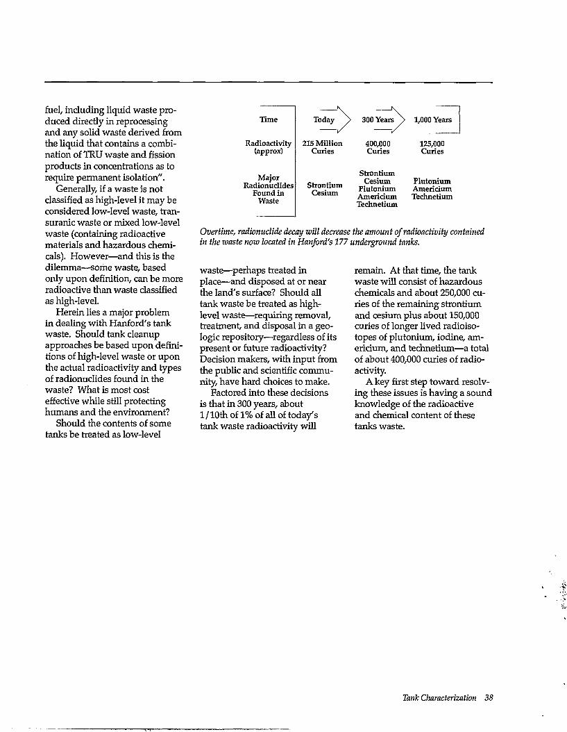
Time
Radioactivity (approx)
Major Radionuclides
Found in Waste
Today \
215 Million Curies
Strontium Cesium
400,000 Curies
Strontium Cesium
Plutonium Americium Technetium
1,000 Years
125,000 Curies
Plutonium Americium Technetium
Overtime, radionuclide decay will decrease the amount of radioactivity contained in the waste now located in Hanford's 177 underground tanks.
fuel, including liquid waste produced directly in reprocessing and any solid waste derived from the liquid that contains a combination of TRU waste and fission products in concentrations as to require permanent isolation".
Generally, if a waste is not classified as high-level it may be considered low-level waste, tran-suranic waste or mixed low-level waste (containing radioactive materials and hazardous chemicals). However—and this is the dilemma—some waste, based only upon definition, can be more radioactive than waste classified as high-level.
Herein lies a major problem in dealing with Hanford's tank waste. Should tank cleanup approaches be based upon definitions of high-level waste or upon the actual radioactivity and types of radionuclides found in the waste? What is most cost effective while still protecting humans and the environment?
Should the contents of some tanks be treated as low-level
waste—perhaps treated in place—and disposed at or near the land's surface? Should all tank waste be treated as high-level waste—requiring removal, treatment, and disposal in a geologic repository—regardless of its present or future radioactivity? Decision makers, with input from the public and scientific community, have hard choices to make.
Factored into these decisions is that in 300 years, about 1 / 10th of 1% of all of today's tank waste radioactivity will
remain. At that time, the tank waste will consist of hazardous chemicals and about 250,000 curies of the remaining strontium and cesium plus about 150,000 curies of longer lived radioisotopes of plutonium, iodine, americium, and technetium—a total of about 400,000 curies of radioactivity.
A key first step toward resolving these issues is having a sound knowledge of the radioactive and chemical content of these tanks waste.
Tank Characterization 38
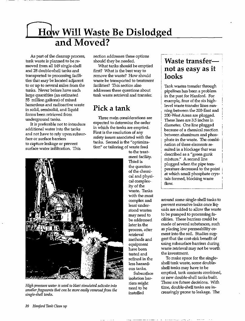
and Moved? As part of the cleanup process,
tank waste is planned to be removed from all 149 single-shell and 28 double-shell tanks and transported to processing facilities that may be located adjacent to or up to several miles from the tanks. Never before have such large quantities (an estimated 55 million gallons) of mixed hazardous and radioactive waste in solid, semisolid, and liquid forms been retrieved from underground tanks.
It is preferable not to introduce additional water into the tanks and not have to rely upon subsurface or surface barriers to capture leakage or prevent surface water infiltration. This
High pressure water is used to blast simulated saltcake into smaller fragments that can be more easily removed from the single-shell tanks.
section addresses these options should they be needed.
What tanks should be emptied first? What is the best way to remove the waste? How should waste be transported to treatment facilities? This section also addresses these questions about tank waste retrieval and transfer.
Pick a tank Three main considerations are
expected to determine the order in which the tanks are emptied. First is the resolution of any safety issues associated with the tanks. Second is the "optimization" or tailoring of waste feed
to the treatment facility. Third is the question of the chemical and physical complexity of the waste. Tanks with the most complex and least understood wastes may need to be addressed later in the process, after retrieval methods and equipment have been tested and refined in the less hazardous tanks.
Subsurface isolation barriers might need to be installed
Waste transfer— not as easy as it looks Tank wastes transfer through pipelines has been a problem in the past for Hanford. For example, four of the six high-level waste transfer lines running between the 200-East and 200-West Areas are plugged. These lines are 3.5 inches in diameter. One line plugged because of a chemical reaction between aluminum and phosphate in the waste. The combination of these elements resulted in a blockage that was described as a "green gunk mixture." A second line plugged when the pipe temperature decreased to the point at which small phosphate crystals formed, blocking waste flow.
around some single-shell tanks to prevent excessive leaks once liquids are added to allow the waste to be pumped to processing facilities. These barriers could be made of several substances, such as placing low permeability cement into the soil. Studies suggest that the cost-risk benefit of using subsurface barriers during waste retrieval may not be worth the investment.
To make space for the single-shell tank waste, some double-shell tanks may have to be emptied, tank contents combined, or new double-shell tanks built. These are future decisions. With time, double-shell tanks are increasingly prone to leakage. The
39 Hanford Tank Clean up
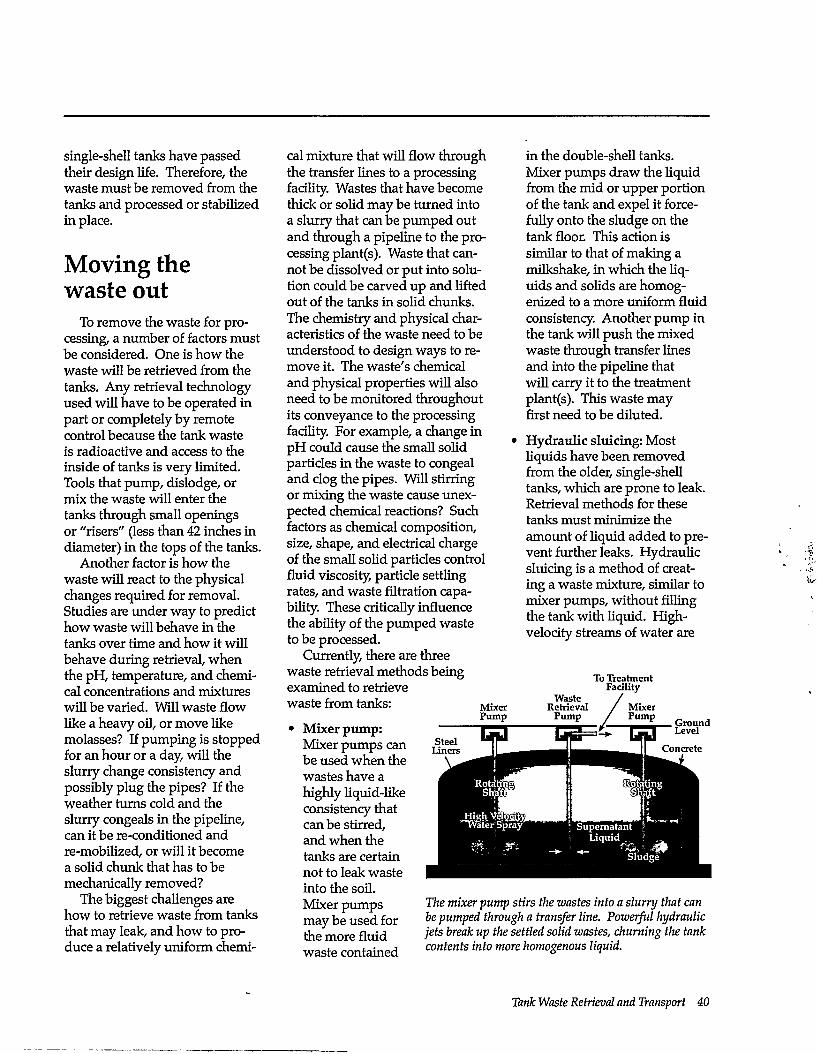
single-shell tanks have passed their design life. Therefore, the waste must be removed from the tanks and processed or stabilized in place.
Moving the waste out
To remove the waste for processing, a number of factors must be considered. One is how the waste will be retrieved from the tanks. Any retrieval technology used will have to be operated in part or completely by remote control because the tank waste is radioactive and access to the inside of tanks is very limited. Tools that pump, dislodge, or mix the waste will enter the tanks through small openings or "risers" (less than 42 inches in diameter) in the tops of the tanks.
Another factor is how the waste will react to the physical changes required for removal. Studies are under way to predict how waste will behave in the tanks over time and how it will behave during retrieval, when the pH, temperature, and chemical concentrations and mixtures will be varied. Will waste flow like a heavy oil, or move like molasses? If pumping is stopped for an hour or a day, will the slurry change consistency and possibly plug the pipes? If the weather turns cold and the slurry congeals in the pipeline, can it be re-conditioned and re-mobilized, or will it become a solid chunk that has to be mechanically removed?
The biggest challenges are how to retrieve waste from tanks that may leak, and how to produce a relatively uniform chemi
cal mixture that will flow through the transfer lines to a processing facility. Wastes that have become thick or solid may be turned into a slurry that can be pumped out and through a pipeline to the processing plant(s). Waste that cannot be dissolved or put into solution could be carved up and lifted out of the tanks in solid chunks. The chemistry and physical characteristics of the waste need to be understood to design ways to remove it. The waste's chemical and physical properties will also need to be monitored throughout its conveyance to the processing facility. For example, a change in pH could cause the small solid particles in the waste to congeal and clog the pipes. Will stirring or mixing the waste cause unexpected chemical reactions? Such factors as chemical composition, size, shape, and electrical charge of the small solid particles control fluid viscosity, particle settling rates, and waste filtration capability. These critically influence the ability of the pumped waste to be processed.
Currently, there are three waste retrieval methods being examined to retrieve waste from tanks:
in the double-shell tanks. Mixer pumps draw the liquid from the mid or upper portion of the tank and expel it forcefully onto the sludge on the tank floor. This action is similar to that of making a milkshake, in which the liquids and solids are homogenized to a more uniform fluid consistency. Another pump in the tank will push the mixed waste through transfer lines and into the pipeline that will carry it to the treatment plant(s). This waste may first need to be diluted.
Hydraulic sluicing: Most liquids have been removed from the older, single-shell tanks, which are prone to leak. Retrieval methods for these tanks must minimize the amount of liquid added to prevent further leaks. Hydraulic sluicing is a method of creating a waste mixture, similar to mixer pumps, without filling the tank with liquid. High-velocity streams of water are
• Mixer pump: Mixer pumps can be used when the wastes have a highly liquid-like consistency that can be stirred, and when the tanks are certain not to leak waste into the soil. Mixer pumps may be used for the more fluid waste contained
Mixer Pump
Waste Retrieval
Pump
To Treatment Facility
Ground Level
The mixer pump stirs the wastes into a slurry that can be pumped through a transfer line. Powerful hydraulic jets break up the settled solid wastes, churning the tank contents into more homogenous liquid.
Tank Waste Retrieval and Transport 40
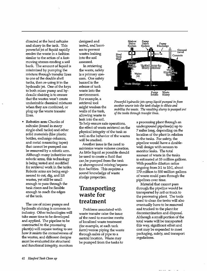
directed at the hard saltcake and slurry in the tank. This powerful jet of liquid rapidly erodes the waste in a fashion similar to the action of a fast-moving stream eroding a soil bank. The amount of liquid is minimized by pumping the mixture through transfer lines to one of the double shell tanks, then re-using it in the hydraulic jet. One of the keys to both mixer pump and hydraulic sluicing is to ensure that the wastes won't create undesirable chemical mixtures when they are combined, or plug up the waste transfer lines.
• Robotics arm: Chunks of saltcake (found in many single-shell tanks) and other solid materials (like plastic bottles, exchange columns, and metal measuring tapes) that cannot be pumped can be removed by a robotic arm. Although many industries use robotic arms, this technology is being tested and modified for retrieval work in the tanks. Robotic arms are being engineered to cut, dig, and lift wastes, yet still be small enough to pass through the tank risers and be flexible enough to reach the edges of the tank.
The use of mixer pumps and hydraulic sluicing is common to industry. Other technologies will take more time to be developed and applied. The pipeline to be constructed to the processing plant(s) will require testing to see how it resists the corrosiveness of the wastes, and different designs must be evaluated for structural and functional integrity, monitors
designed and tested, and barriers to prevent wastes leaking into the soil assessed.
In retrieving the waste, safety is a primary concern. One safety hazard is the release of tank waste into the environment. For example, a retrieval tool might weaken the walls of the tank, allowing waste to leak into the soil. To help ensure safe operations, the effect of waste retrieval on the physical integrity of the tank as well as the behavior of the wastes will be studied.
Another issue is the need to minimize waste volume creation. As little liquid as possible should be used to create a fluid that canbe pumped from the tank or aboveground mixing/separation facilities. This requires a sound knowledge of waste sludge properties.
Transporting waste for treatment
Problems associated with waste transfer raise the issue of the need to examine merits of localized waste treatment (for example, at each tank farm) versus piping the waste through miles of pipe to a central location. Waste may be pumped from the tanks to
Sluicer Drive
System Pump Drive
System Pump
Discharge Ground Level
Pump Waste Intake Slurry
Powerful hydraulic jets spray liquid pumped in from another source into the tank sludge to dilute and mobilize the waste. The resulting slurry is pumped out of the tanks through transfer lines.
a processing plant through an underground pipeline(s) up to 7 miles long, depending on the location of the plant in relation to the tanks. For safety, the pipeline would have a double-wall design with sensors to monitor leaks. The total amount of waste in the tanks is estimated at 55 million gallons. With possible dilution ratios ongoing from 3:1 to 10:1, about 170 million to 550 million gallons of waste could pass through the pipelines over time.
Material that cannot pass through the pipeline would be transported by rail or truck to the processing plant. The tools used to clean the tanks will also eventually have to be removed and trucked to the plant for decontamination and disposal. Although a small portion of the total waste will be transported this way, significant effort and cost may be expended to meet packaging, safety, and transport regulations.
41 Hanford Tank Clean up
Containing some waste in place?
Nearly 50% of Hanford's single-shell tanks are known or suspected to have leaked. More tanks will leak as they continue to age. Because large volumes of fluid may be added to tanks to retrieve the thicker wastes, subsurface barriers may be needed beneath a tank or group of tanks to contain potential leaks. Barriers can also minimize the chance for new leaks to drive previously leaked waste deeper into the soil.
Surface barriers can be used to minimize surface water from infiltrating contaminated soil and carrying toxic materials deeper into the soil.
Three major challenges are faced in developing barriers. The first is developing or identifying the best materials. The barriers must meet containment criteria, and the materials may have to fulfill many functions: effectively capture or block the movement of contaminants, last tens to hundreds of years, and /or be resistant to high-pH liquids or radioactivity. The second challenge is developing enabling technology—how is a
large barrier emplaced? Avenues such as directional well drilling, subsurface cement or chemical injection, and soil freezing or superheating are being explored. The final challenge is how to find out whether the barrier was put in place correctly and is working. Ways are needed to check the integrity of barriers that may be located tens of feet below the surface, and then measure the barriers' effectiveness. Devices such as in-situ sensors and sound-wave scanners are possible methods.
Simulating waste Possibly one of the most sig
nificant problems affecting the success of the waste retrieval process is how the chemicals in the waste will interact when they are mixed into a slurry and piped to the processing plant(s). Samples of tank waste are expensive to get and time-consuming to analyze, so computer programs are being designed that simulate how waste is expected to behave. Nonradioactive simulated wastes that behave like real wastes are being developed to test waste transport processes safely.
These simulated wastes minimize the risk of worker exposure to hazardous radioactive materials and lower costs associated with using actual tank wastes. For example, simulated wastes are being used as part of an investigation into the causes of the periodic hydrogen gas "burps" from double-shell tank 241-SY-101. Using nonradioactive mixtures that simulate the chemical and physical behavior of the waste in this tank, specialists are studying the mechanisms involved in the generation and release of the gas. Data gathered from experiments with simulated waste are compared to data derived from tank waste to make sure the simulants reflect actual waste behavior. This research will help discover safe, effective methods of preventing hydrogen gas buildup and allow prediction of similar occurrences in other tanks.
How well simulated waste mimics the chemical and physical properties of the actual waste remains an open question. How many actual waste samples must be studied before a representative simulant is made is unknown.
Tank Waste Retrieval and Transport 42
Once the waste has been retrieved from the tanks, it must be treated and packaged into a form that will prevent radiation and hazardous chemicals from reaching humans and the environment. Preparing waste for final treatment is called pretreatment. This is a critical step in tank cleanup for it is when most radionuclides are first separated from the bulk of the chemicals and metals making up the waste. Efficient pretreatment processes save time and money. They also lessen the volume of high-level waste to be later stored onsite or in a geologic repository. At the same time, there are major waste processing risks and performance uncertainties unsolved in waste pretreatment. How much pretreatment and separation is necessary? This section addresses this and other questions about waste pretreatment and separation.
Two separate streams
Most of the waste in the tanks is composed of nonradioactive material, such as water and sodium salts (for example, sodium nitrate and sodium nitrite). For reference, Hartford's 149 single-shell tanks contain about 190,000 tons of chemicals and 12 million gallons of drainable and non-drainable water; the 28 double-shell tanks hold 55,000 tons of chemicals and 17 million gallons of water. Radionuclides are typically a few tenths of one percent of the waste mass. Nonetheless, this small fraction makes some of the tank waste dangerous if
it should come in contact with humans. The tanks contain approximately 215 million curies of radioactivity (about 99% is from cesium, strontium, and their decay products). Radiation within some tanks can reach several hundred rad per hour, much higher than exposure safety standards. If the radionuclides can be separated from this waste, the larger volume of chemical waste, containing trace amounts of radioactivity, can be disposed of at much less expense than the more highly radioactive waste. For this reason, waste processing at Hartford is often described as containing two "streams": one each for low-level and high-level waste. (Low-level and high-level refer to the amount of radiation in the waste. See Glossary.)
A lot divided is a little
Leaving the waste unseparated means that all 55 million gallons (65% in single-shell tanks and 35% in double-shell tanks) of tank waste could be classified as high-level waste. High-level waste may eventually be disposed of in a deep geologic repository in Nevada (see section on Storing the Waste Forms). This repository is designed to hold 77,000 tons (70,000 metric tons) of waste from all over the country. The repository program was designed before DOE began its environmental cleanup program beginning in 1989. Experts estimate that the Hartford tank waste could make thousand's of glass "logs." Commonly quoted numbers range from 10,000 to
40,000 logs. The number of logs created will depend upon the efficiency of waste processing, glass chemistry, and waste loading within each log. For example, if no low-level waste was created and therefore all tank waste was processed into glass logs, approximately 200,000 logs could be manufactured. Because high-level waste is difficult and costly to handle, transport, and process, the volume of disposed waste needs to be reduced. When most of the radionuclides are separated from the waste, the remaining chemical waste is easier and less costly to process and dispose.
Gathering information
To determine what is in each tank, chemically and radiologi-cally, and how best to pretreat it requires waste characterization. Historical records of plutonium production at Hanford show that many tanks contain some general components used to dissolve uranium (for example, nitric acid) and organic chemicals used to separate plutonium (for example, bismuth phosphate or tributyl phosphate; see Appendix B). Caustic chemicals (sodium hydroxide) were added to neutralize the corrosiveness of this acidic mixture before it was discharged to the tanks. Some tanks also contain ferrocyanide, which was used to settle radioactive byproducts such as cesium out of tank liquids for later removal. Physically, the tank waste is a mixture of liquids, slurries, sludges, and solids.
43 Hanford Tank Clean up
Researchers need access to actual tank samples to develop technologies to pretreat the waste. Experiments on simulated wastes provide some information; however, proof that new technologies really work can only be confirmed through testing on actual waste samples. The key issue involves risk. How much risk (in terms of technical success/failure, cost, schedule, and potential human health impact) is acceptable before proceeding with each critical step of tank cleanup? Technology demonstrations using actual waste samples will decrease long-term risks. New technologies in waste process control, dissolution, washing, and leaching must be demonstrated to prove they are safe, efficient, and cost-effective.
Only then can chemists and engineers knowledgeably design the facilities and waste treatment processes to turn the tank waste into a final form for permanent storage.
Pretreat and wash Pretreatment begins by sepa
rating the solids from the liquids and washing the solids to remove any liquid retained between the solid particles and to dissolve soluble materials. The liquid contains a high concentration of dissolved salts (for example, sodium nitrate and nitrite) and also the radionuclide cesium. Once the cesium is removed (probably by ion exchange), the remaining radioactivity may be
low enough that the liquid can be converted to an insoluble form and disposed of as low-level waste. The solids and liquids may either be separated in the tanks by settling the solids (which contain most of the strontium and plutonium) and pumping out the liquid. Because this liquid will still contain some suspended solids, a second separation or "polishing" step might be done in a processing facility using filtration or centrifuge technology.
If these are the only steps taken to pretreat the waste before packaging it into its final form, the remaining waste would still be classified as high-level waste because the liquid contains cesium. By removing the cesium, the liquids might be treated as
Waste Processing Activities sm Chemicals
Radionuclides
I T a n k I W Liquids, W m- Solids, W> Y Slurry W I Sludge J
Sludge Dissolving
Solid/Liquid Separation
Radionuclide Separation
Chemical Separation
Organic Destuction
\
• if Interim
• if Interim
ODDDD DDD •
Waste Waste Pre-Treatment/ Interim Waste Waste Characterization Retrieval Separation Storage Processing/
Immobilization Disposal
I Low-Level I k Waste W ^ F Vitrification ^ t V (Mostly F | Chemical) j
Onsite Vaults
I High-Level J k Waste k ^ F Vitrification ^ F Y (Mostly F
Radionuclides)
Onsite Storage
Offsite Repository
Some pretreatment
and separation done
Note: Liquid evaporation and effluent treatment used as required throughout process
Scientists must use a variety of methods to reduce the amount of high-level waste created.
Pretreatment and Separation 44
Tank waste can he separated into a low-level and high-level radioactive waste stream. By making assumptions about waste separation efficiency and waste loading, the volumes of final waste material generated can he estimated. This example assumes a 25% waste loading.
low-level radioactive waste. This could significantly reduce the amount of high-level radioactive waste sent to a geologic repository or stored onsite.
The issue of potentially approaching high-level waste treatment and disposal based upon concentration limits versus being source-based is contentious. Its resolution will impact the technologies needed for Hanford cleanup.
Ways are being studied to wash and dissolve waste in strong chemical solutions (acids or bases) to either remove chemicals that would hinder putting waste into its final form or unnecessarily add to the volume of this waste. For example, if the waste were to be vitrified into a glass, the amount of aluminum, phosphorus, and chromium would need to be reduced because they tend to interfere with forming a durable, high-level waste glass. In addition, removal of these metals reduces the overall volume of high-level waste glass logs created.
Remove the radionuclides
The amount of separation needed will depend on what amount of radioactivity is allowable in the final low-level waste. This radioactivity, in turn, affects how the waste can be disposed and what kind of protection workers and equipment will need to process the waste. Most of the radionuclides will be processed into a high-level waste glass form.
The volume of low-level waste created from tank cleanup is projected to be about 10 times greater than the volume of high-level waste. However, the high-level waste is more dangerous than the low-level waste and will require isolation for thousands of years.
Separate the chemicals
One challenge of tank waste cleanup is to separate the radionuclides from the nonradioactive chemicals and irunimize the amount of high-level and low-level waste to be stored. Other waste streams generated by the cleanup process can also be minimized and some chemicals, such
as sodium hydroxide and nitric acid, can be recycled.
Chemical separations methods are under development because there are different chemical constituents in the tank waste that respond to some methods and not to others. For example, cesium and technetium, expected to be in the liquid fraction of the waste, require separation using similar but different processes: a cation ion exchange process for the cesium (attracted to a negative charge), and an anion exchange process for technetium (attracted to a positive charge). These exchange processes work in much the same way as a common water softener used in homes, which releases sodium into the water flowing through the unit and
45 Hanford Tank Clean up
Specially developed resins such as resorcinol-formaldehyde, packed into an exchanger column, can capture and hold some hazardous and radioactive chemicals when liquid waste flows through the column. This process is called ion exchange.
Electron microscope photos show the before and after results of unwashed and base-washed phosphate-rich sludge. Fine particles and large grains are removed, leaving only larger uranium-rich particles that can be treated separately.
holds the water's calcium and magnesium cations in the exchanger column. With specially developed materials packed into the exchanger columns, these processes can release harmless components into the liquid waste while attracting and holding radionuclides or other
hazardous chemicals. Cesium extraction is a proven technology. However, technetium extraction is an unknown.
Uranium, strontium, pluto-nium, aluminum, phosphates, and silica that have little solubility in alkaline (basic) solutions are likely to remain as solid particles in the waste. Stronger chemical separation methods such as acid washing (adding nitric acid or hydrofluoric acid to the waste) may be required to dissolve these chemical compounds so the fission products that are in solid form with them can be separated from the liquid by other pro
cesses such as solvent extraction (adding an immiscible liquid solvent to the waste that attracts specific chemical elements out of the waste that can then be removed). The need for these and other separation measures is driven by waste form composition criteria and cost.
Destroy the organic compounds
As radiation breaks down the organic compounds in the tanks, flammable gases such as hydrogen are produced. Some tanks contain organic complexants that, along with small suspended particles, could interfere with separation processes to remove radionuclides such as strontium from the low-level waste. Therefore, the quantity of organic compounds in the waste and which specific compounds are present need to be known. If waste washing cannot remove these compounds, other methods will be developed to destroy the compounds.
The final cycle Even though tank waste, as a
whole, forms a mixture of radioactive and inorganic chemicals, some of the wastes are less complex than others. For this reason, existing technologies are believed adequate to begin the waste cleanup in some tanks—especially the less complex waste found in some of the double-shell tanks (see Appendix C). There is no substitute for actual cleanup experience. However, technologies must be developed to clean up other Hanford tanks. This is driven not only by the nature of the waste but also by the need to reduce human and environmental risks, significantly lesson the cost of cleanup, and minimize the volume of waste end-products.
Pretreatment and Separation 46
olMifying Tank Waste for Disposal Tank waste must be converted
into a durable solid form before it is disposed. This is so that after hundreds to thousands of years, radioactive and chemical materials remaining in the waste can't easily escape and come into contact with plants, animals, or humans at concentrations that exceed acceptable limits. The low-level portions of the tank waste can be turned into a waste form and stored to allow retrieval if needed. The high-level radioactive waste must be turned into a form that is safe for interim storage likely on the Hanford Site until a permanent waste repository is opened to receive the waste. What kinds of materials are strong enough to hold waste for generations into the future? How are these solid materials made? And what is science's role in designing the best possible waste form? This section addresses these and other questions about solidifying tank waste.
Liquids in, solids out
As this booklet discussed in earlier sections, waste is removed from the tanks to be pretreated. The resulting waste has the consistency of watery mud. This can't just be placed in metal containers and disposed. The waste is too liquid, which would make it easier to leak chemicals and radionuclides into the environment. Therefore, it is converted into a stable, solid form.
Hard as a rock and acts like one, too
For years, scientists have been exploring the best ways to solidify waste. One approach is to trap the waste in a rocklike glass mixture. Most disposal options for Hartford's high-and low-level radioactive waste use glass as a final waste form. Glass is resistant to radiation damage, durable, won't catch on fire, and is not susceptible to biodegradation. Glass can be melted or softened at temperatures above 1400°F to 1500°F. Another idea is to make the waste into a ceramic product made by baking of a nonmetallic mineral such as cement or brick. A third alternative is a combined glass and ceramic form. An alternate being considered for low-level waste resembles pieces of broken glass mixed in cement. The glass pieces contain the waste.
These forms physically and chemically "lock in" the waste materials. In fact, the waste materials become trapped in the molecular structure of the glass or ceramic material. It's like making a rock—once the waste materials are hardened inside, they can't easily be released.
When high-level tank waste is turned into glass, it looks like this — hard, shiny, and rocklike. This glass traps radioactive and chemical materials and keep them from easily escaping, even if the glass cracks or gets wet.
Waste forms are created in a ceramic-lined metal container called a melter. During operation melters have a useful life expectancy of about 2 years. Therefore, the 15 plus year processing of Hanford's waste will require many melters to be used and disposed.
In the melter, tank waste and dry materials that form glass or ceramics are mixed together at high temperatures, ranging from 1400°F to 2700°F. This mixture is poured into log-shaped, steel containers (often about 2 feet in diameter and 10 to 15 feet long), where it cools and hardens. DOE plans to store and monitor the containers until a permanent disposal area is selected. The chemical form for the storage of low-level radioactive waste remains under study. Alternatives considered have included creating large glass monoliths; mixing glass in a
47 Hanford Tank Clean up
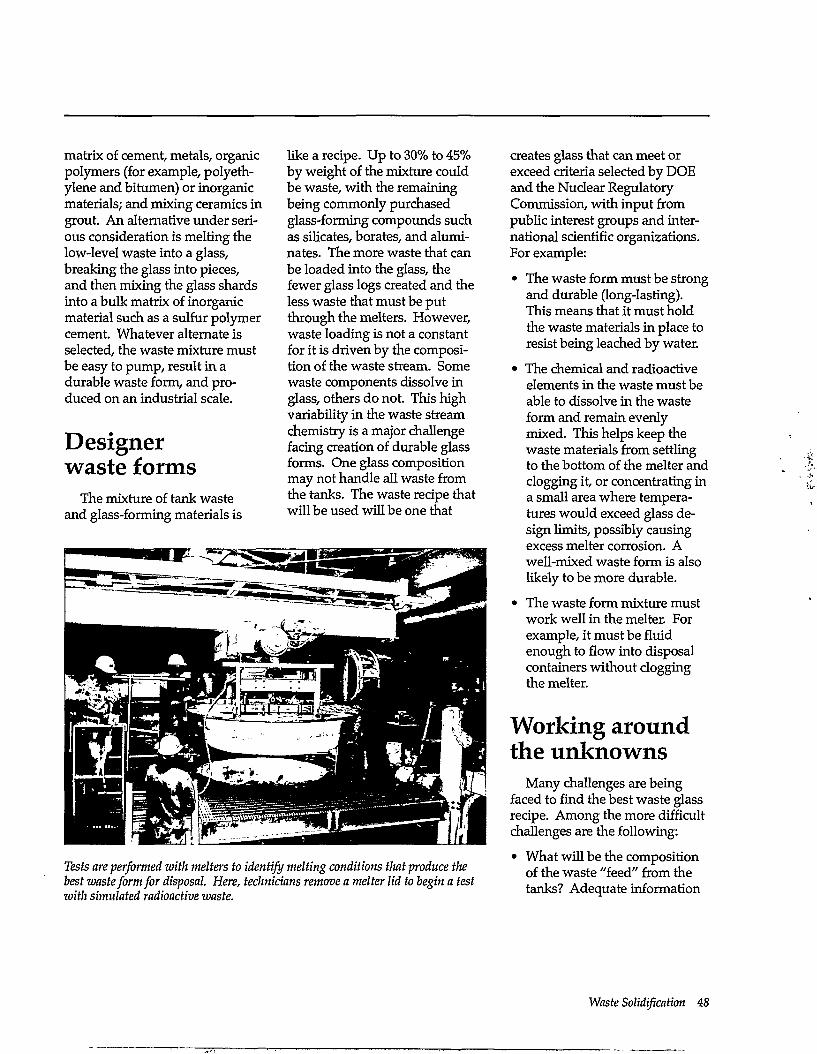
matrix of cement, metals, organic polymers (for example, polyethylene and bitumen) or inorganic materials; and mixing ceramics in grout. An alternative under serious consideration is melting the low-level waste into a glass, breaking the glass into pieces, and then mixing the glass shards into a bulk matrix of inorganic material such as a sulfur polymer cement. Whatever alternate is selected, the waste mixture must be easy to pump, result in a durable waste form, and produced on an industrial scale.
Designer waste forms
The mixture of tank waste and glass-forming materials is
like a recipe. Up to 30% to 45% by weight of the mixture could be waste, with the remaining being commonly purchased glass-forming compounds such as silicates, borates, and alumi-nates. The more waste that can be loaded into the glass, the fewer glass logs created and the less waste that must be put through the melters. However, waste loading is not a constant for it is driven by the composition of the waste stream. Some waste components dissolve in glass, others do not. This high variability in the waste stream chemistry is a major challenge facing creation of durable glass forms. One glass composition may not handle all waste from the tanks. The waste recipe that will be used will be one that
Tests are performed with melters to identify melting conditions that produce the best waste form for disposal. Here, technicians remove a melter lid to begin a test with simulated radioactive waste.
creates glass that can meet or exceed criteria selected by DOE and the Nuclear Regulatory Commission, with input from public interest groups and international scientific organizations. For example:
• The waste form must be strong and durable (long-lasting). This means that it must hold the waste materials in place to resist being leached by water.
• The chemical and radioactive elements in the waste must be able to dissolve in the waste form and remain evenly mixed. This helps keep the waste materials from settling to the bottom of the melter and clogging it, or concentrating in a small area where temperatures would exceed glass design limits, possibly causing excess melter corrosion. A well-mixed waste form is also likely to be more durable.
• The waste form mixture must work well in the melter. For example, it must be fluid enough to flow into disposal containers without clogging the melter.
Working around the unknowns
Many challenges are being faced to find the best waste glass recipe. Among the more difficult challenges are the following:
• What will be the composition of the waste "feed" from the tanks? Adequate information
Waste Solidification 48
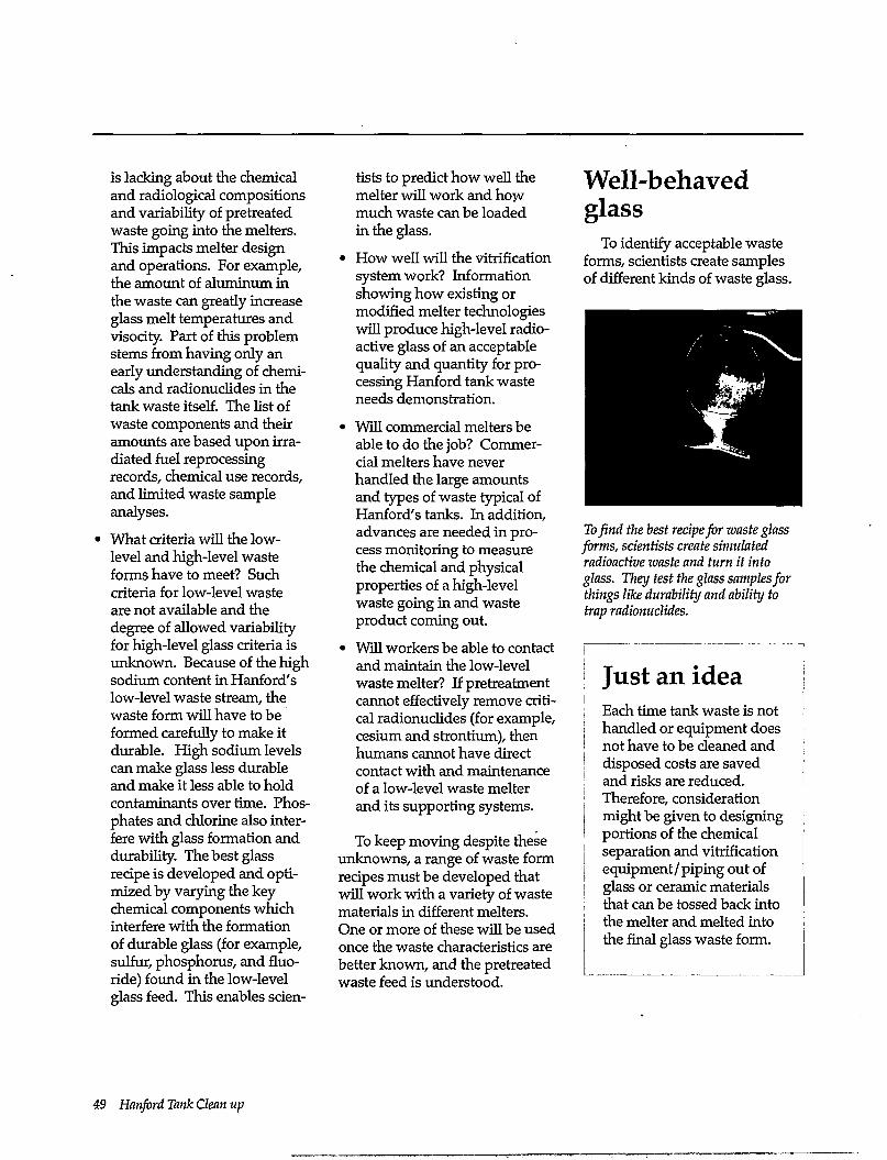
is lacking about the chemical and radiological compositions and variability of pretreated waste going into the melters. This impacts melter design and operations. For example, the amount of aluminum in the waste can greatly increase glass melt temperatures and visocity. Part of this problem stems from having only an early understanding of chemicals and radionuclides in the tank waste itself. The list of waste components and their amounts are based upon irradiated fuel reprocessing records, chemical use records, and limited waste sample analyses.
What criteria will the low-level and high-level waste forms have to meet? Such criteria for low-level waste are not available and the degree of allowed variability for high-level glass criteria is unknown. Because of the high sodium content in Hanford's low-level waste stream, the waste form will have to be formed carefully to make it durable. High sodium levels can make glass less durable and make it less able to hold contaminants over time. Phosphates and chlorine also interfere with glass formation and durability. The best glass recipe is developed and optimized by varying the key chemical components which interfere with the formation of durable glass (for example, sulfur, phosphorus, and fluoride) found in the low-level glass feed. This enables scien
tists to predict how well the melter will work and how much waste can be loaded in the glass.
• How well will the vitrification system work? Information showing how existing or modified melter technologies will produce high-level radioactive glass of an acceptable quality and quantity for processing Hanford tank waste needs demonstration.
• Will commercial melters be able to do the job? Commercial melters have never handled the large amounts and types of waste typical of Hanford's tanks. In addition, advances are needed in process monitoring to measure the chemical and physical properties of a high-level waste going in and waste product coming out.
• Will workers be able to contact and maintain the low-level waste melter? If pretreatment cannot effectively remove critical radionuclides (for example, cesium and strontium), then humans cannot have direct contact with and maintenance of a low-level waste melter and its supporting systems.
To keep moving despite these unknowns, a range of waste form recipes must be developed that will work with a variety of waste materials in different melters. One or more of these will be used once the waste characteristics are better known, and the pretreated waste feed is understood.
Well-behaved glass
To identify acceptable waste forms, scientists create samples of different kinds of waste glass.
To find the best recipe for waste glass forms, scientists create simulated radioactive waste and turn it into glass. They test the glass samples for things like durability and ability to trap radionuclides.
| Just an idea ; Each time tank waste is not ! handled or equipment does 1 not have to be cleaned and J disposed costs are saved ! and risks are reduced.
Therefore, consideration might be given to designing portions of the chemical separation and vitrification equipment/piping out of
| glass or ceramic materials that can be tossed back into the melter and melted into the final glass waste form.
49 Hanford Tank Clean up
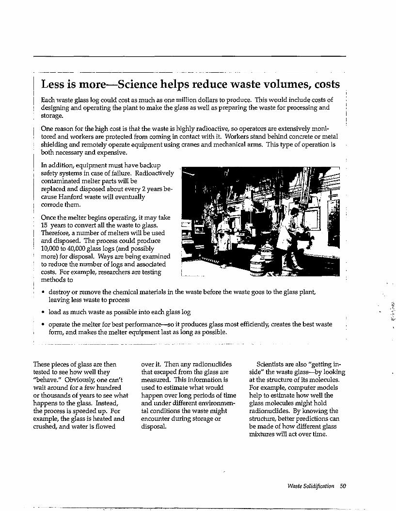
Less is more—Science helps reduce waste volumes, costs Each waste glass log could cost as much as one million dollars to produce. This would include costs of designing and operating the plant to make the glass as well as preparing the waste for processing and storage.
One reason for the high cost is that the waste is highly radioactive, so operators are extensively monitored and workers are protected from coming in contact with it. Workers stand behind concrete or metal shielding and remotely operate equipment using cranes and mechanical arms. This type of operation is both necessary and expensive.
In addition, equipment must have backup safety systems in case of failure. Radioactively contaminated melter parts will be replaced and disposed about every 2 years because Hanford waste will eventually corrode them.
Once the melter begins operating, it may take 15 years to convert all the waste to glass. Therefore, a number of melters will be used and disposed. The process could produce 10,000 to 40,000 glass logs (and possibly more) for disposal. Ways are being examined to reduce the number of logs and associated costs. For example, researchers are testing methods to
• destroy or remove the chemical materials in the waste before the waste goes to the glass plant, leaving less waste to process
• load as much waste as possible into each glass log
• operate the melter for best performance—so it produces glass most efficiently, creates the best waste form, and makes the melter equipment last as long as possible.
These pieces of glass are then tested to see how well they "behave." Obviously, one can't wait around for a few hundred or thousands of years to see what happens to the glass. Instead, the process is speeded up. For example, the glass is heated and crushed, and water is flowed
over it. Then any radionuclides that escaped from the glass are measured. This information is used to estimate what would happen over long periods of time and under different environmental conditions the waste might encounter during storage or disposal.
Scientists are also "getting inside" the waste glass—by looking at the structure of its molecules. For example, computer models help to estimate how well the glass molecules might hold radionuclides. By knowing the structure, better predictions can be made of how different glass mixtures will act over time.
Waste Solidification 50
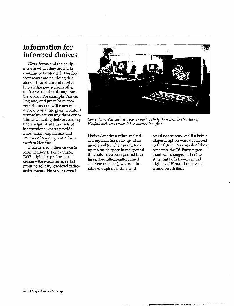
Information for informed choices
Waste forms and the equipment in which they are made continue to be studied. Hanford researchers are not doing this alone. They share and receive knowledge gained from other nuclear waste sites throughout the world. For example, France, England, and Japan have converted—or soon will convert— nuclear waste into glass. Hanford researches are visiting these countries and sharing their processing knowledge. And hundreds of independent experts provide information, experience, and reviews of ongoing waste form work at Hanford.
Citizens also influence waste form decisions. For example, DOE originally preferred a cement-like waste form, called grout, to solidify low-level radioactive waste. However, several
Computer models such as these are used to study the molecular structure of Hanford tank waste when it is converted into glass.
Native American tribes and citizen organizations saw grout as unacceptable. They said it took up too much space in the ground (it would have been poured into large, 1.4-million-gallon, lined concrete trenches), was not durable enough over time, and
could not be removed if a better disposal option were developed in the future. As a result of these concerns, the Tri-Party Agreement was changed in 1994 to state that both low-level and high-level Hanford tank waste would be vitrified.
51 Hanford Tank Clean up
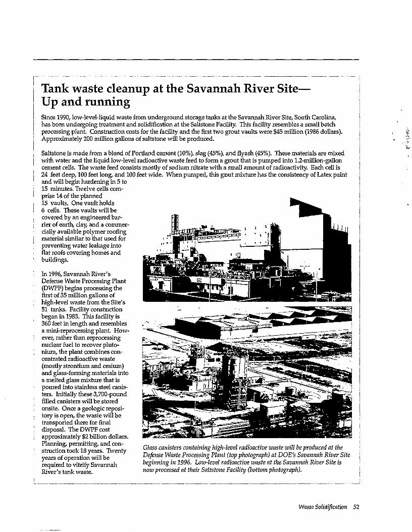
Tank waste cleanup at the Savannah River Site— Up and running Since 1990, low-level-liquid waste from underground storage tanks at the Savannah River Site, South Carolina, has been undergoing treatment and solidification at the Saltstone Facility. This facility resembles a small batch processing plant. Construction, costs for the facility and the first two grout vaults were $45 million (1986 dollars). Approximately 200 million gallons of saltstone will be produced.
Saltstone is made from a blend of Portland cement (10%), slag (45%), and flyash (45%). These materials are mixed with water and the liquid low-level radioactive waste feed to form a grout that is pumped into 1.2-million-gallon cement cells. The waste feed consists mostly of sodium nitrate with a small amount of radioactivity. Each cell is 24 feet deep, 100 feet long, and 100 feet wide. When pumped, this grout mixture has the consistency of Latex paint and will begin hardening in 5 to 15 minutes. Twelve cells comprise 14 of the planned 15 vaults. One vault holds
j 6 cells. These vaults will be I covered by an engineered bar-j rier of earth, clay, and a commer
cially available polymer roofing material similar to that used for preventing water leakage into flat roofs covering homes and buildings.
In 1996, Savannah River's Defense Waste Processing Plant (DWPF) begins processing the first of 35 million gallons of high-level waste from the Site's 51 tanks. Facility constriction began in 1983. This facility is 360 feet in length and resembles a mini-reprocessing plant. However, rather than reprocessing nuclear fuel to recover pluto-nium, the plant combines concentrated radioactive waste (mostly strontium and cesium) and glass-forming materials into a melted glass mixture that is poured into stainless steel canisters. Initially these 3,700-pound filled canisters will be stored onsite. Once a geologic repository is open, the waste will be transported there for final disposal. The DWPF cost
i approximately $2 billion dollars. I Planning, permitting, and con-I struction took 18 years. Twenty ! years of operation will be j required to vitrify Savannah I River's tank waste.
Glass canisters containing high-level radioactive waste will be produced at the Defense Waste Processing Plant (top photograph) at DOE's Savannah River Site beginning in 1996. Low-level radioactive waste at the Savannah River Site is now processed at their Saltstone Facility (bottom photograph).
Waste Solidification 52
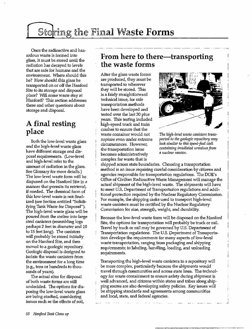
torins: the Final Waste Forms Once the radioactive and haz
ardous waste is formed into glass, it must be stored until the radiation has decayed to levels that are safe for humans and the environment. Where should this be? How should this glass be transported on or off the Hanford Site to its storage and disposal place? Will some waste stay at Hanford? This section addresses these and other questions about storage and disposal.
A final resting place
Both the low-level waste glass and the high-level waste glass have different storage and disposal requirements. (Low-level and high-level refer to the amount of radiation in the glass. See Glossary for more details.) The low-level waste form will be disposed on the Hanford Site in a manner that permits its retrieval, if needed. The chemical form of this low-level waste is not finalized (see Section entitled "Solidifying Tank Waste for Disposal"). The high-level waste glass will be poured from the melter into large steel canisters (resembling logs perhaps 2 feet in diameter and 10 to 15 feet long). The canisters will probably be stored initially on the Hanford Site, and then moved to a geologic repository. Geologic disposal is designed to isolate the waste canisters from the environment for a long time (e.g., tens or hundreds to thousands of years).
The actual sites for disposal of both waste forms are still undecided. The options for disposing the low-level waste glass are being studied, considering issues such as the effects of soil,
The high-level waste canisters transported to the geologic repository may look similar to this spent-fuel cask containing irradiated uranium from a nuclear reactor.
From here to there—transporting the waste forms After the glass waste forms are produced, they must be transported to wherever they will be stored. This is a fairly straightforward technical issue, for safe transportation methods have been developed and tested over the last 30 plus years. This testing included high-speed truck and train crashes to ensure that the waste container would not rupture even under extreme circumstances. However, the transportation issue becomes administratively complex for waste that is shipped across state boundaries. Choosing a transportation method is an issue requiring careful consideration by citizens and agencies responsible for transportation regulations. The DOE's Office of Civilian Radioactive Waste Management will manage the actual shipment of the high-level waste. The shipments will have to meet U.S. Department of Transportation regulations and additional protection required by the Nuclear Regulatory Commission. For example, the shipping casks used to transport high-level waste canisters must be certified by the Nuclear Regulatory Commission for size, strength, weight, and durability.
Because the low-level waste form will be disposed on the Hanford Site, the options for transportation will probably be truck or rail. Travel by truck or rail may be governed by U.S. Department of Transportation regulations. The U.S. Department of Transportation develops the requirements for many aspects of low-level waste transportation, ranging from packaging and shipping requirements; to labeling, handling, loading, and unloading requirements.
Transporting the high-level waste canisters to a repository will be more complex, particularly because the shipments would travel through communities and across state lines. The technology for waste containment to ensure safety during shipment is well advanced, and citizens within states and tribes along shipping routes are also developing safety policies. Key issues will be shipping standards and agreements among communities and local, state, and federal agencies.
53 Hanford Tank Clean up
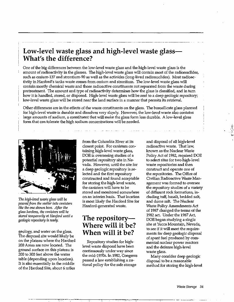
I Low-level waste glass and high-level waste glass— | What's the difference?
One of the big differences between the low-level waste glass and the high-level waste glass is the amount of radioactivity in the glasses. The high-level waste glass will contain most of the radionuclides, such as cesium-137 and strontium-90 as well as the actinides (long-lived radionuclides). Most radioactivity in Hartford's tanks waste comes from cesium and strontium. The low-level waste glass will contain mostly chemical waste and those radioactive constituents not separated from the waste during pretreatment. The amount and type of radioactivity determines how the glass is classified, and in turn
J how it is handled, stored, or disposed. High-level waste glass will be sent to a deep geologic repository; I low-level waste glass will be stored near the land surface in a manner that permits its retrieval. !
Other differences are in the effects of the waste constituents on the glass. The borosilicate glass planned ' for high-level waste is durable and dissolves very slowly. However, the low-level waste also contains
large amounts of sodium, a constituent that will make the glass form less durable. Alow-level glass form that can tolerate the high sodium concentrations will be needed.
The high-level waste glass will be poured from the melter into canisters like the one shown here. After the glass hardens, the canisters will he stored temporarily at Hanford until a geologic repository is ready.
geology, and water on the glass. The disposal site would likely be on the plateau where the Hanford 200 Areas are now located. The ground surface on this plateau is 200 to 300 feet above the water table (depending upon location). It is also essentially in the middle of the Hanford Site, about 6 miles
from the Columbia River at its closest point. For canisters containing high-level waste glass, DOE is overseeing studies of a potential repository site in Nevada. However, until the site for a deep geologic repository is selected and the first repository constructed and found acceptable for storing the high-level waste, the canisters will have to be stored and monitored somewhere on an interim basis. That location is most likely the Hanford Site for Hanford-generated waste.
The repository— Where will it be? When will it be?
Repository studies for high-level waste disposal have been continuously under way since the mid-1970s. In 1982, Congress passed a law establishing a national policy for the safe storage
and disposal of all high-level radioactive waste. That law, known as the Nuclear Waste Policy Act of 1982, required DOE to select sites for two high-level waste repositories and then construct and operate one of the repositories. The Office of Civilian Radioactive Waste Management was formed to oversee the repository studies of a variety of different rock formations, including tuff, basalt, bedded salt, and dome salt. The Nuclear Waste Policy Amendments Act of 1987 changed the terms of the 1982 act. Under the 1987 Act, DOE began studying a single site at Yucca Mountain, Nevada, to see if it will meet the requirements for deep geologic disposal of spent fuel produced by commercial nuclear power reactors and the defense high-level waste glass.
Many consider deep geologic disposal to be a reasonable method for storing the high-level
Waste Storage 54
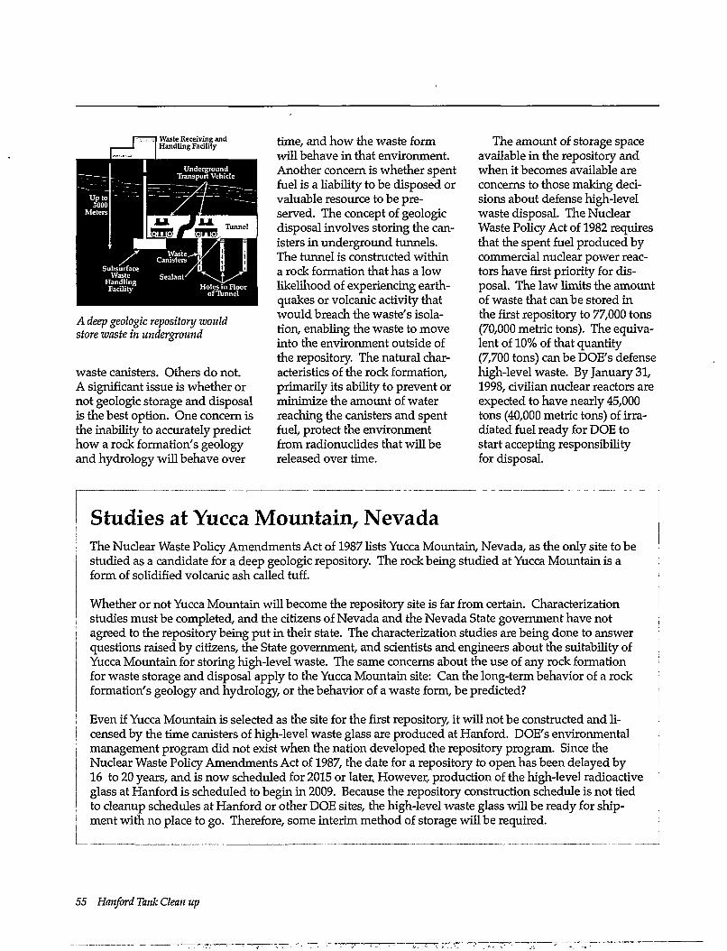
Waste Receiving and Handling Facility
Underground Transport Vehicle
Waste.. Canisters
Subsurface Waste
Handling Facility Holes
of Tunnel
A deep geologic repository would store waste in underground
waste canisters. Others do not. A significant issue is whether or not geologic storage and disposal is the best option. One concern is the inability to accurately predict how a rock formation's geology and hydrology will behave over
time, and how the waste form will behave in that environment. Another concern is whether spent fuel is a liability to be disposed or valuable resource to be preserved. The concept of geologic disposal involves storing the canisters in underground tunnels. The tunnel is constructed within a rock formation that has a low likelihood of experiencing earthquakes or volcanic activity that would breach the waste's isolation, enabling the waste to move into the environment outside of the repository. The natural characteristics of the rock formation, primarily its ability to prevent or minimize the amount of water reaching the canisters and spent fuel, protect the environment from radionuclides that will be released over time.
The amount of storage space available in the repository and when it becomes available are concerns to those making decisions about defense high-level waste disposal. The Nuclear Waste Policy Act of 1982 requires that the spent fuel produced by commercial nuclear power reactors have first priority for disposal. The law limits the amount of waste that can be stored in the first repository to 77,000 tons (70,000 metric tons). The equivalent of 10% of that quantity (7,700 tons) can be DOE's defense high-level waste. By January 31, 1998, civilian nuclear reactors are expected to have nearly 45,000 tons (40,000 metric tons) of irradiated fuel ready for DOE to start accepting responsibility for disposal.
Studies at Yucca Mountain, Nevada The Nuclear Waste Policy Amendments Act of 1987 lists Yucca Mountain, Nevada, as the only site to be studied as a candidate for a deep geologic repository. The rock being studied at Yucca Mountain is a form of solidified volcanic ash called tuff.
Whether or not Yucca Mountain will become the repository site is far from certain. Characterization studies must be completed, and the citizens of Nevada and the Nevada State government have not agreed to the repository being put in their state. The characterization studies are being done to answer questions raised by citizens, the State government, and scientists and engineers about the suitability of Yucca Mountain for storing high-level waste. The same concerns about the use of any rock formation for waste storage and disposal apply to the Yucca Mountain site: Can the long-term behavior of a rock formation's geology and hydrology, or the behavior of a waste form, be predicted?
Even if Yucca Mountain is selected as the site for the first repository, it will not be constructed and licensed by the time canisters of high-level waste glass are produced at Hanford. DOE's environmental management program did not exist when the nation developed the repository program. Since the Nuclear Waste Policy Amendments Act of 1987, the date for a repository to open has been delayed by 16 to 20 years, and is now scheduled for 2015 or later. However, production of the high-level radioactive glass at Hanford is scheduled to begin in 2009. Because the repository construction schedule is not tied to cleanup schedules at Hanford or other DOE sites, the high-level waste glass will be ready for shipment with no place to go. Therefore, some interim method of storage will be required.
55 Hanford Tank Clean up
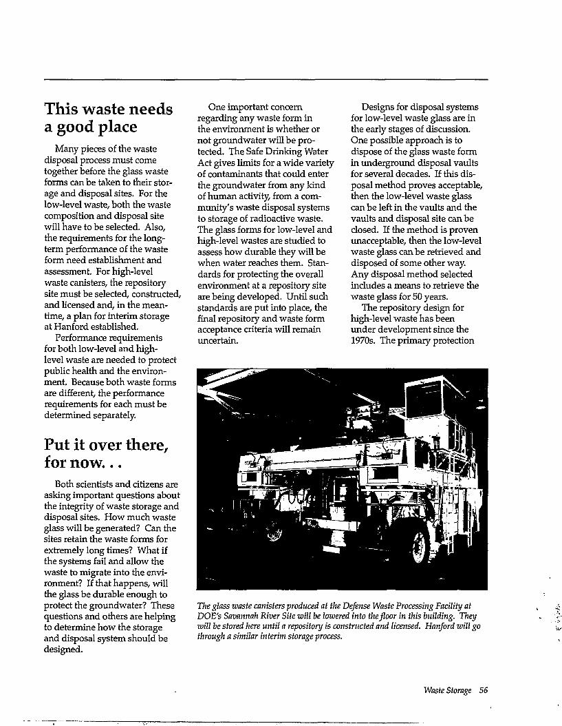
This waste needs a good place
Many pieces of the waste disposal process must come together before the glass waste forms can be taken to their storage and disposal sites. For the low-level waste, both the waste composition and disposal site will have to be selected. Also, the requirements for the long-term performance of the waste form need establishment and assessment. For high-level waste canisters, the repository site must be selected, constructed, and licensed and, in the meantime, a plan for interim storage at Hanford established.
Performance requirements for both low-level and high-level waste are needed to protect public health and the environment. Because both waste forms are different, the performance requirements for each must be determined separately.
Put it over there, for now...
Both scientists and citizens are asking important questions about the integrity of waste storage and disposal sites. How much waste glass will be generated? Can the sites retain the waste forms for extremely long times? What if the systems fail and allow the waste to migrate into the environment? If that happens, will the glass be durable enough to protect the groundwater? These questions and others are helping to determine how the storage and disposal system should be designed.
One important concern regarding any waste form in the environment is whether or not groundwater will be protected. The Safe Drinking Water Act gives limits for a wide variety of contaminants that could enter the groundwater from any kind of human activity, from a community's waste disposal systems to storage of radioactive waste. The glass forms for low-level and high-level wastes are studied to assess how durable they will be when water reaches them. Standards for protecting the overall environment at a repository site are being developed. Until such standards are put into place, the final repository and waste form acceptance criteria will remain uncertain.
Designs for disposal systems for low-level waste glass are in the early stages of discussion. One possible approach is to dispose of the glass waste form in underground disposal vaults for several decades. If this disposal method proves acceptable, then the low-level waste glass can be left in the vaults and the vaults and disposal site can be closed. If the method is proven unacceptable, then the low-level waste glass can be retrieved and disposed of some other way. Any disposal method selected includes a means to retrieve the waste glass for 50 years.
The repository design for high-level waste has been under development since the 1970s. The primary protection
The glass waste canisters produced at the Defense Waste Processing Facility at DOE's Savannah River Site will be lowered into the floor in this building. They will be stored here until a repository is constructed and licensed. Hanford will go through a similar interim storage process.
Waste Storage 56
from waste releases in unacceptable quantities is the engineered barriers surrounding the waste canisters and the local geology. The canisters and barrier materials are placed in the repository. After the repository is full, it is backfilled.
Designs for interim disposal methods for the high-level waste form are still being determined. At DOE's Savannah River Site, the Defense Waste Processing
Facility, where that site's high-level waste is made into glass, includes a building designed for interim storage of the high-level waste canisters. The canisters are lowered into the building floor, which is constructed to allow monitoring and eventual retrieval of the canisters. A similar method may be considered for Hanford's canisters of high-level waste glass.
Another issue is what methods could be used to warn future generations about the presence of a low-level waste disposal site or a deep geologic repository. Symbols and warning signs placed on top of and around the sites, plus historical records, may offer the best protection to warn others interested in exploring, drilling, or otherwise using these waste sites.
57 Hanford Tank Clean up
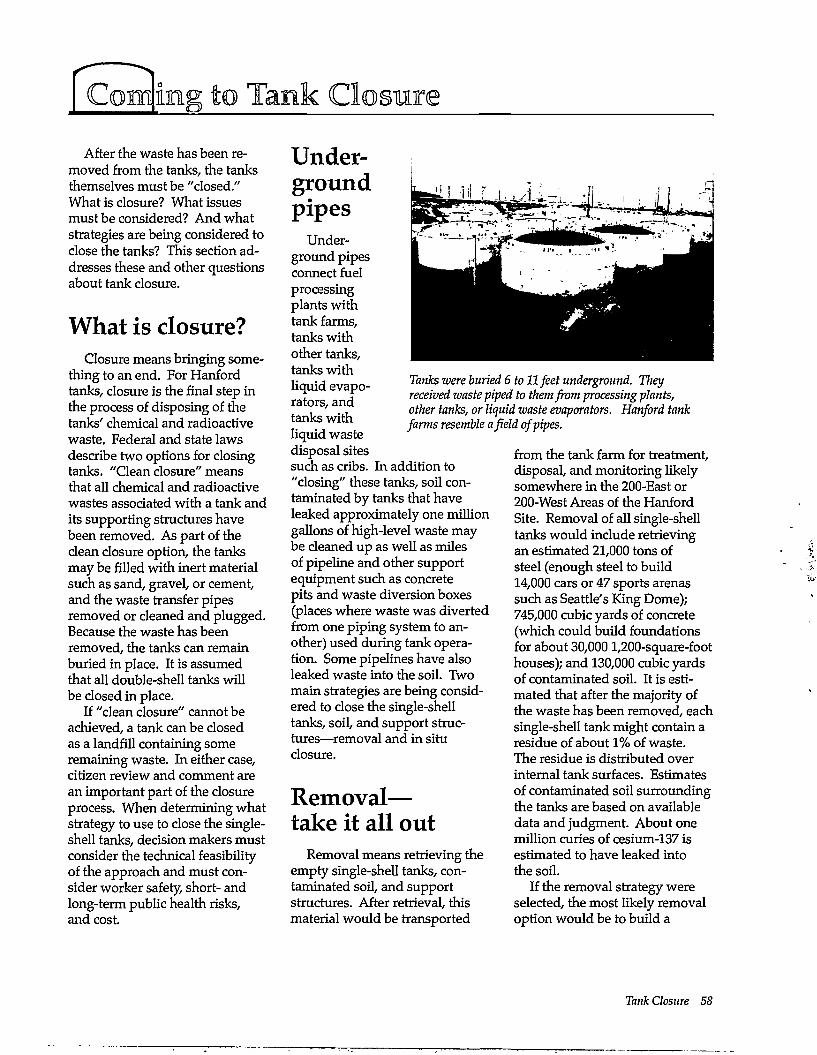
Coming to Tank Closure After the waste has been re
moved from the tanks, the tanks themselves must be "closed." What is closure? What issues must be considered? And what strategies are being considered to close the tanks? This section addresses these and other questions about tank closure.
What is closure? Closure means bringing some
thing to an end. ForHanford tanks, closure is the final step in the process of disposing of the tanks' chemical and radioactive waste. Federal and state laws describe two options for closing tanks. "Clean closure" means that all chemical and radioactive wastes associated with a tank and its supporting structures have been removed. As part of the clean closure option, the tanks may be filled with inert material such as sand, gravel, or cement, and the waste transfer pipes removed or cleaned and plugged. Because the waste has been removed, the tanks can remain buried in place. It is assumed that all double-shell tanks will be closed in place.
If "clean closure" cannot be achieved, a tank can be closed as a landfill containing some remaining waste. In either case, citizen review and comment are an important part of the closure process. When determining what strategy to use to close the single-shell tanks, decision makers must consider the technical feasibility of the approach and must consider worker safety, short- and long-term public health risks, and cost.
Underground pipes
Underground pipes connect fuel processing plants with tank farms, tanks with other tanks, tanks with liquid evaporators, and tanks with liquid waste disposal sites such as cribs. In addition to "closing" these tanks, soil contaminated by tanks that have leaked approximately one million gallons of high-level waste may be cleaned up as well as miles of pipeline and other support equipment such as concrete pits and waste diversion boxes (places where waste was diverted from one piping system to another) used during tank operation. Some pipelines have also leaked waste into the soil. Two main strategies are being considered to close the single-shell tanks, soil, and support structures—removal and in situ closure.
Removal— take it all out
Removal means retrieving the empty single-shell tanks, contaminated soil, and support structures. After retrieval, this material would be transported
Tanks were buried 6 to 11 feet underground. They received waste piped to them from processing plants, other tanks, or liquid waste evaporators. Hanford tank farms resemble afield of pipes.
from the tank farm for treatment, disposal, and monitoring likely somewhere in the 200-East or 200-West Areas of the Hanford Site. Removal of all single-shell tanks would include retrieving an estimated 21,000 tons of steel (enough steel to build 14,000 cars or 47 sports arenas such as Seattle's King Dome); 745,000 cubic yards of concrete (which could build foundations for about 30,0001,200-square-foot houses); and 130,000 cubic yards of contaminated soil. It is estimated that after the majority of the waste has been removed/each single-shell tank might contain a residue of about 1% of waste. The residue is distributed over internal tank surfaces. Estimates of contaminated soil surrounding the tanks are based on available data and judgment. About one million curies of cesium-137 is estimated to have leaked into the soil.
If the removal strategy were selected, the most likely removal option would be to build a
Tank Closure 58
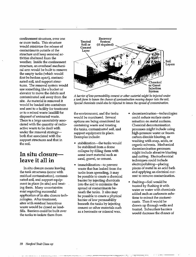
A barrier of low-permeability cement or other material might be injected under a tank farm to lessen the chance of contamination moving deeper into the soil. Special chemicals could also be injected to lessen the spread of contamination.
confinement structure, over one or more tanks. This structure would minimize the release of contaminants outside of the structure and keep removal activities sheltered from the weather. Inside the confinement structure, an overhead mechanical arm would be built to remove the empty tanks (which would first be broken apart), contaminated soil, and support structures. The removal system would use something like a bucket or elevator to move the debris and contaminated soil away from the site. As material is removed it would be loaded into containers and sent to a facility for treatment or to a mixed waste landfill for disposal of untreated waste. There is a large uncertainty associated with the quantity of radioactive waste to be dealt with under the removal strategy— both that associated with the support structures and that in the soil.
In situ closure— leave it all in
In situ closure means leaving the tank structures (some with residual contamination), contaminated soil, and support equipment in place (in situ) and treating them. Many uncertainties exist regarding successful application of in situ closure technologies. After treatment, sites with residual hazardous waste would be closed as landfills. Barriers could be built over the tanks to isolate them from
the environment, and the tanks would be monitored. Several options are being considered for containing waste and treating the tanks, contaminated soil, and support equipment in place. Examples include:
• stabilization—the tanks would be stabilized from a dome collapse by filling them with some inert material such as sand, gravel, or cement.
• immobilization—to prevent waste that has leaked from the tanks from spreading, it may be possible to create a chemical barrier by injecting chemicals into the soil to minimize the spread of contaminants beneath the tanks. It also may be possible to create a physical barrier of low permeability beneath the tanks by injecting cement or other materials such as a bentonite or mineral wax.
• decontamination—technologies could reduce surface contamination on metal surfaces. Chemical decontamination processes might include using high-pressure water or frozen carbon dioxide blasting, or washing with soap, acids, or organic solvents. Mechanical decontamination processes might include abrasive blasting and cutting. Electrochemical techniques could include electropolishing—placing pieces of metal in an acid bath and applying an electrical current to remove contamination.
• flushing—Soil would be treated by flushing it with water or water with chemicals added such as carbonate solutions to extract the contaminants. Then it would be drawn up through wells and treated. Subsurface barriers would decrease the chance of
59 Hanford Tank Clean up
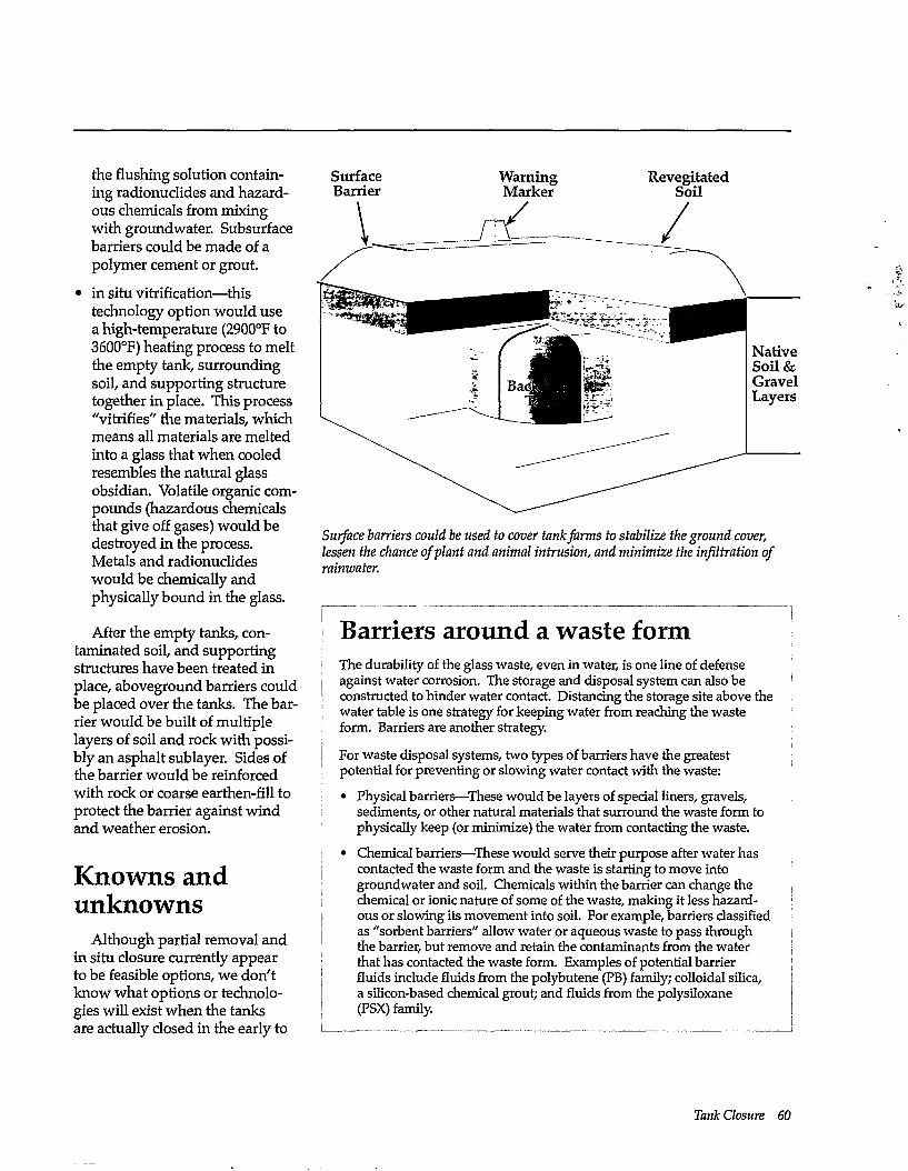
the flushing solution containing radionuclides and hazardous chemicals from mixing with groundwater. Subsurface barriers could be made of a polymer cement or grout.
• in situ vitrification—this technology option would use a high-temperature (2900°F to 3600°F) heating process to melt the empty tank, surrounding soil, and supporting structure together in place. This process "vitrifies" the materials, which means all materials are melted into a glass that when cooled resembles the natural glass obsidian. Volatile organic compounds (hazardous chemicals that give off gases) would be destroyed in the process. Metals and radionuclides would be chemically and physically bound in the glass.
After the empty tanks, contaminated soil, and supporting structures have been treated in place, aboveground barriers could be placed over the tanks. The barrier would be built of multiple layers of soil and rock with possibly an asphalt sublayer. Sides of the barrier would be reinforced with rock or coarse earthen-fill to protect the barrier against wind and weather erosion.
Knowns and unknowns
Although partial removal and in situ closure currently appear to be feasible options, we don't know what options or technologies will exist when the tanks are actually closed in the early to
Surface Barrier
Warning Marker
Revegitated Soil
Native Soil& Gravel Layers
Surface barriers could be used to cover tank farms to stabilize the ground cover, lessen the chance of plant and animal intrusion, and minimize the infiltration of rainwater.
Barriers around a waste form The durability of the glass waste, even in water, is one line of defense against water corrosion. The storage and disposal system can also be constructed to hinder water contact. Distancing the storage site above the water table is one strategy for keeping water from reaching the waste form. Barriers are another strategy.
For waste disposal systems, two types of barriers have the greatest potential for preventing or slowing water contact with the waste:
• Physical barriers—These would be layers of special liners, gravels, sediments, or other natural materials that surround the waste form to physically keep (or minimize) the water from contacting the waste.
• Chemical barriers—These would serve their purpose after water has contacted the waste form and the waste is starting to move into groundwater and soil. Chemicals within the barrier can change the chemical or ionic nature of some of the waste, making it less hazardous or slowing its movement into soil. For example, barriers classified as "sorbent barriers" allow water or aqueous waste to pass through the barrier, but remove and retain the contaminants from the water that has contacted the waste form. Examples of potential barrier fluids include fluids from the polybutene (PB) family; colloidal silica, a silicon-based chemical grout; and fluids from the polysiloxane (PSX) family.
Tank Closure 60
perhaps mid-twenty-first century. What we do know is that tank closure options selected will depend upon:
• the health risk and cost of removing tanks and their support structures versus leaving them in place
• the efficiency and effectiveness of tank waste cleanup
• state of future technology such as in place immobilization and stabilization techniques
• regulatory policy and stakeholder preferences.
One of the most important questions about Hanford cleanup and tank waste cleanup is land use. The land currently occupied by the tank farms might eventually be used for agriculture, for industrial purposes, or be withdrawn from uses other than waste management. Each use would require a different closure strategy and different cost to taxpayers. Land use planning can be a tool for identifying realistic cleanup goals; however, as a 1994 report from the U.S. General Accounting Office mentions, land use planning should not be used
as a "crutch for not cleaning up." The need for cleanup standards tied to land use is particularly urgent. Unfortunately, no federal standards exist for cleaning up radionuclides in soil, aside from standards for uranium mill tailings. These issues must be dealt with before the tanks can be closed, and, indeed, before the Hanford Site can be cleaned up.
61 Hanford Tank Clean up
How to Get Involved in Hanf ord Tank Waste Cleanup
The DOE, EPA, and Washington State Department of Ecology are working together to cleanup Hanford wastes, including those in the tanks. Quarterly information meetings are held in the Tri-Cities and one other city alternated in the Northwest to update the public on cleanup progress and issues. To get on the mailing list for this and other information or to express a concern, call 1-800-321-2008 or write to
Hanford Mailing List: Informational Mailings P.O. Box 1970 B3-35 Richland, WA 99352
or
Hanford Update Department of Ecology P.O. Box 47600 Olympia, WA 98504
Other agencies and organizations to contact include the following: Federal and State Organizations Oregon Department of Energy Dirk Dunning (503) 378-3187 or in Oregon 1-800-221-8035 625 Marion Street NE Salem, OR 97310
U.S. Department of Energy/ Hanford Advisory Board JonYerka 509-376-9628 Public Involvement Coordinator U.S. Department of Energy P.O. Box 550 Richland, WA 99352
U.S. Environmental Protection Agency Dennis Faulk (509)376-8631 712 Swift Blvd., Suite S. Richland, WA 99352
Washington State Department of Ecology Nuclear and Mixed Waste Management Program Laurie Davies (360) 407-7113 P.O.Box 47600 Olympia, WA 98504
Environmental and Professional Organizations American Nuclear Society Gerald Woodcock (509) 376-5224 1851 Alder Ave. Richland, WA 99352
Columbia River United Cyndy DeBruler (509)493-2808 P.O. Box 912 Bingen, WA 98605
Hanford Education Action League Lynne Stembridge (509)326-3370 N. 1720 Ash Street Spokane, WA 99205
Heart of America Northwest Gerald Pollett (206) 382-1014 1305 4th Ave., Suite 208 Seattle, WA 98101
Indian Nations The Confederated Tribes and Bands of the Yakama Indian Nation Russell Jim (509) 865-5121 Route 1 Box 78A White Swan, WA 98952
Confederated Tribes of the Umatilla Indian Reservation Bill Burke (503) 276-3165 P.O. Box 638 Pendleton, OR 97801
Nez Perce Tribe Allen Slickpoo, Sr. (208) 843-2253 P.O. Box 305 Lapwai, ID 83540
Getting Involved 62
Resources For more information on
Hanford waste tanks or cleanup, please consult information materials at the following public reading rooms:
Branford-Price Miller Library (503) 725-3690 Portland State University S. W. Harrison and Park P.O. Box 1151 Portland, OR 97201
DOE Public Reading Room (509) 376-8583 Washington State University at Tri-Cities Campus 100 Sprout Road Room 130 West Richland, WA 99352
Foley Center (509) 328-4420, extension 3125 Gonzaga University E. 502 Boone Spokane, WA 99258
Suzzallo Library (206) 543-4664 Government Publications Room FM-25 University of Washington Seattle, WA 98195
Additional information can be found in the resources listed in the reference list of this guide.
63 Hanford Tank Clean up
ssary aquifer—a permeable geologic formation that can hold and transmit large quantities of groundwater
background radiation—radiation from natural radioactive materials always present in the environment, including radiation from the sun and outer space, and radioactive elements in the upper atmosphere, the ground, building materials, and the human body. The national average radiation dose from natural sources is about 300 millirem per year.
CERCLA—Comprehensive Environmental Response, Compensation, and Liability Act of 1986; the federal statute that provides for the compensation, liability, cleanup, and emergency response for hazardous substances released into the environment and for the cleanup of inactive waste disposal sites. CERCLA was amended in 1986 and applied to waste sites owned by the federal government.
contamination— radioactive or hazardous chemical materials where they are not wanted or in a concentration that threatens human health or environmental health.
critical mass—the mass of radioactive material that is enough to begin a nuclear chain reaction. For plutonium-239 and uranium-235, this is about 25 and 110 pounds, respectively.
curie (Ci)—a basic unit to describe the intensity (strength) of radioactivity in a material. A curie is a measure of the rate at which a radioactive material gives off particles and disintegrates. It is also the amount of radioactivity in 1 gram of the isotope radium-226. One curie equals 37 billion disintegrations per second. A typical home smoke detector contains about 1 millionth of a curie of radioactivity.
defense waste—radioactive waste resulting from weapons research and development, the operation of naval reactors, the production of weapons material such as plutonium, the reprocessing of defense spent fuel, and the decommissioning of nuclear-powered ships and submarines.
disposal—removal of contamination or contaminated material from the human environment, although with provisions for monitoring, control, and maintenance
dose—a quantity of radiation or energy absorbed; measured in rads or rem
double-shell tank—a reinforced concrete underground vessel with two inner steel liners. Instruments are placed in the space between the liners (the annulus) to detect liquid waste leaks from the inner liner.
effective dose equivalent—an estimate of the total risk of potential health effects from radiation exposure.
engineered barrier—a human-made structure, such as an earthen mound, used to improve the isolation or stabilization potential of a waste site.
exposure—the act of being exposed to a harmful agent, such as breathing air containing some hazardous agent like radioactive materials, smoke, lead, or germs; coming in contact with some hazardous agent (for example getting radioactive material or poison ivy on the skin); being present in an energy field such as sunlight or other external radiation; or ingesting a hazardous agent.
fission—the process of an atom splitting into roughly equal parts. It is triggered by absorption of a neutron.
hazardous waste—nonradioactive waste such as metals (lead, mercury) and other compounds that pose a risk to the environment and human health.
high-level waste—highly radioactive material (containing fission products, traces of uranium and plutonium, and other radioactive elements); it usually results from chemical reprocessing of nuclear fuel used in nuclear reactors.
isotopes—different forms of the same chemical element distinguished by different numbers of neutrons in the nucleus. A single element may have many isotopes; for example, there are 14 isotopes ofamericium. Some isotopes may be radioactive; others may not be radioactive.
Glossary 64
low-level waste—waste containing radioactive elements that are generally short-lived (decay to nonradioactive materials quickly usually in less than a few months) or that has low levels of radioactivity This waste is not classified as high-level waste, transuranic waste, or spent nuclear fuel.
mixed waste—waste that contains both radioactive and hazardous waste components.
rad—acronym for radiation absorbed dose; a unit of radioactivity that measures the amount, or dose, of radiation absorbed by any material, such as human tissue. Rad is the amount of radiation absorbed; rem (see below) is the potential damage done to a human from that absorption.
radiation—particles or energy waves emitted from an unstable element or nuclear reaction.
radioactivity—property possessed by some isotopes of elements of emitting radiation (alpha, beta, or gamma rays) spontaneously in their decay process.
radionuclide—radioactive atomic species or isotopes of an element.
65 Hanford Tank Clean up
rem—an acronym for roentgen equivalent man; a unit of radiation dose that indicates the potential for impact on human cells. "Quality factors" (such as 10 for beta particles and 20 for alpha particles) are given to different kinds of radiation to convert rad to rem.
RCRA—Resource Conservation and Recover Act of 1976, the federal law that regulates the management of hazardous waste, including the hazardous component of radioactive mixed waste, at operating facilities. Sometimes referred to as the "cradle to grave" management of hazardous waste. With respect to DOE site cleanup, RCRA is concerned with the assessment and cleanup of waste sites and sites associated with operating facilities.
risk—the probability that a detrimental effect will occur. Examples include an unwanted health effect from exposure to a toxic substance or the failure of a technology to perform as expected.
single-shell tank—an older-style underground vessel with a single steel wall liner surrounded by reinforced concrete. The domes of single-shell tanks are made of concrete without an inner covering of steel.
tank—underground vessel used to store waste materials. At Hanford, two types exist— single-shell tanks and double-shell tanks.
tank waste—radioactive mixed waste materials left over from the production of nuclear materials and stored in underground tanks.
transuranic element—elements, such as plutonium and neptunium, that have atomic numbers (number of protons in the nucleus) greater than 92. All are radioactive.
transuranic waste—waste contaminated with alpha-emitting transuranic elements with half-lives greater than 20 years in concentrations of more than 1 ten-millionth of a curie per gram (0.03 ounce) of waste.
waste—unwanted materials left over from production of nuclear materials. Waste was either stored in above or below ground structures or released into the environment.
Watch List—a list of tanks published in Public Law 101-510, Section 3137; also called the Wyden Bill. The law requires DOE to treat listed tanks in such a way as to avoid any potential releases of materials to the environment.
water table—the upper surface in an aquifer where the pore spaces in the geologic formation are filled with water that moves down a hydraulic gradient.
Reference List 10 CFR 61, "Licensing Requirements for Land Disposal of Radioactive Wastes." U.S. Nuclear Regulatory Commission, Code of Federal Regulations.
1991. "U.S. Department of Energy Report to U.S. Congress on Waste Tank Safety Issues at the Hanford Site." (Wyden report)
1991. "Minutes of Meeting of the Advisory Committee on Nuclear Facility Safety." Washington, DC.
10 CFR 61.55, "Waste Classification." U.S. Nuclear Regulatory Commission, Code of Federal Regulations.
40 CFR 264, Subpart G. "Closure and Post Closure." U.S. Environmental Protection Agency, Code of Federal Regulations.
Alumkal, W T., H. Babad, H. D. Harmon, and D. D. Wodrich. 1994. The Hanford Site Tank Waste Remediation System: An Update. WHC-SA-2124-FP, Westinghouse Hanford Company, Richland, Washington.
Anderson, J. D. 1990. A History of the 200 Area Tank Farms. WHC-MR-0132, Westinghouse Hanford Company, Richland, Washington.
Babad, H., and J. L. Deichman. 1991. Hanford High-Activity Waste Tank Safety Issues. WHC-SA-1017-FP, Westinghouse Hanford Company, Richland, Washington.
Babad, H., R. J. Cash, J. L. Deichman, and G. D. Johnson. 1993. "High-Priority Hanford Site Radioactive Waste Storage Tank Safety Issues: An Overview," Journal of Hazardous Materials, 35(1993):427-441.
Babad, H., M. D. Crippen, D. A. Truner, and M. A. Gerber. 1993. "Resolving the Safety Issue for Radioactive Waste Tanks with High Organic Content." WHC-SA-1671 in Hanford Site Tank Waste Remediation System Waste Management 1993 Symposium Papers and Viewgraphs, WHC-MR-0413, Westinghouse Hanford Company, Richland, Washington.
Bamberger, J. A., B. M. Wise, and W. C. Miller. Retrieval Technology Development for Hanford Double-Shell Tanks. Proceedings of the International Topical Meeting on Nuclear and Hazardous Waste Management and Spectrum 92, American Nuclear Society Grange Park, Illinois, pp 700-705.
Boomer, K. D., J. S. Garfield, K. A. Giese, B. A. Higly, J. S. Layman, A. L. Boldt, N. R. Croskrey, C. E. Golberg, L. J. Johnson, and R. J. Parazin. 1990. Functional Requirements Baseline for the Closure of Single-Shell Tanks. WHC-EP-0338, Westinghouse Hanford Company, Richland, Washington.
Boomer, K. D., et al. 1993. Tank Waste Options Report. WHC-EP-616, Westinghouse Hanford Company, Richland, Washington.
Broz,R.E. 1994. Tank Farms Hazards Assessment. WHC-SD-PRP-HA-013, Rev. 0, Westinghouse Hanford Company, Richland, Washington.
Bunker, B. C, J. W. Virden, W. L. Kuhn, and R. K. Quinn. 1995. "Nuclear Materials, Radioactive Tank Wastes." In Encyclopedia of Energy Technology and the Environment, John Wiley & Sons Inc., New York.
Clever, D., and L. Lange. 1994. "Steam Eruption Averted in Waste Tank at Hanford." Seattle Post-Intelligencer, Thursday, August 4.
Colton,N.G. 1995. Sludge Pre-treatment Chemistry Evaluation: Enhanced Sludge Washing Separation Factors. PNL-10512, Pacific Northwest Laboratory, Richland, Washington.
Cox, J. L., S. A. Bryan, D. M. Camaioni, R. T. Hallen, M. A. Lilga, G. J. Lumetta, J. R. Morrey, V. B. Schneider, D. W Wester, and C. R. Yonker. 1993. Proceedings of the First Hanford Separation Science Workshop. PNL-SA-21775, Pacific Northwest Laboratory, Richland, Washington.
deBruler,G. 1994. Hanford and the River. Columbia River United, Bingen, Washington.
Defense Nuclear Safety Board. 1993. Recommendations of the Defense Nuclear Safety Board Regarding Hanford Single-Shell Waste Tanks.
Dirkes, R. L., R. W. Hanf, R. K. Woodruff, and R. E. Lundgren. 1994. Hanford Site Environmental Report for Calendar Year 1993. PNL-9823, Pacific Northwest Laboratory, Richland, Washington.
DOE (U.S. Department of Energy). Reprint 1986. Managing the Nation's Nuclear Waste. DOE/RW-0036, U.S. Department of Energy, Office of Civilian Radioactive Waste Management, Washington, D.C.
References 66
DOE (U.S. Department of Energy). 1987. Final Environmental Impact Statement, Disposal of Hanford Defense High-Level, Transuranic and Tank Waste, Hanford Site, Richland, Washington. DOE/EIS-0113, U.S. Department of Energy, Washington, D.C.
DOE (U.S. Department of Energy) Order 5820.2A "Radioactive Waste Management." September 26 1988.
DOE (U.S. Department of Energy) and Lawrence Berkeley Laboratory. 1990. "Investigation of Potential Flammable Gas Accumulation in Hanford Tank 101-SY." Investigation team of DOE West Valley, DOE Savannah River, and Lawrence Berkeley Laboratory.
DOE (U.S. Department of Energy). 1993. 2993 Year in Review: A Look at Waste Management and Environmental Restoration at Hanford. U.S. Department of Energy, Richland, Washington.
DOE (U.S. Department of Energy). 1993. Overview of the 1993 Site-Specific Plan. U.S. Department of Energy, Richland, Washington.
DOE (U.S. Department of Energy). 1994. Efficient Separations and Processing Integrated Program (ESP-IP) Technology Summary. 1994. DOE/EM-0126P, National Technical Information Service, Springfield, Virginia.
DOE (U.S. Department of Energy). 1994. Tank Waste Remediation System Integrated Technology Plan. DOE/RL-92-61, Rev. 1, U.S. Department of Energy, Richland, Washington.
Dresel, P. E., S. P. Luttrell, J. C. Evans, W. D. Webber, P. D. Thorne, M. A. Chamness, B. M. Gillespie, B. E. Opitz, J. T. Rieger, andJ.KMerz. 1994. Hanford Site Ground-Water Monitoring for 1993. PNL-10082, Pacific Northwest Laboratory, Richland, Washington.
Elmore, M. R., N. G. Colton, and E. O. Jones. 1994. Development of Simulated Tank Wastes for the U.S. Department of Energy's Underground Storage Tank Integrated Demonstration. Pacific Northwest Laboratory, Richland, Washington.
GAO (U.S. General Accounting Office). 1990. "Consequences of Explosion of Hartford's Single-Shell Tanks Are Understated." GAO/RCED/91-34 Nuclear Energy, U.S. GAO Report to the Chairman, Environment, Energy, and Natural Resources Subcommittee, Committee on Government Operations, House of Representatives, U.S. General Accounting Office, Washington, D.C.
GAO (U.S. General Accounting Office). Yucca Mountain Project Behind Schedule and Facing Major Scientific Uncertainties. GAO/ RCED-93-124, U.S. General Accounting Office, Washington, D.C.
GAO (U.S. General Accounting Office). 1994. Nuclear Cleanup: Completion of Standards and Effectiveness of Land Use Planning Are Uncertain. GAO/RCED-94-114, U.S. General Accounting Office, Washington, D.C.
Gerber,M.A. 1992. Review of Technologies for the Pretreatment of Retrieved Single-Shell Tank Waste at Hanford. PNL-7810, Pacific Northwest Laboratory, Richland, Washington.
Gerber,M. S. 1992. Legend and Legacy: Fifty Years of Defense Production at the Hanford Site. WHC-MR-0293, Revision 2, Westinghouse Hanford Company, Richland, Washington.
Gerber,M. S. 1992. On the Home Front: The Cold War Legacy of the Hanford Nuclear Site. University of Nebraska Press, Omaha.
Groves, L.R. 1962. Now It Can Be Told. Harper and Brothers, New York.
Hanlon,B.M. 1995. Waste Tank Summary for Month Ending June 30,1995. WHC-EP-0182-87, Westinghouse Hanford Company, Richland, Washington.
Heart of America Northwest. Date unknown. Fact Sheet. "Heart of American Northwest Analysis Reveals High Levels of Radioactive Contaminants Found in Columbia River From Hanford." Heart of America Northwest, Seattle, Washington.
High-Level Tank Advisory Panel. 1992. "Approach to Resolution of Safety Issues Associated with Fer-rocyanides in the Hanford Waste Tanks."
Izatt, R. D., H. Babad, W. T. Dixon, and R. L. Lerch. 1990. The Hanford Site: Then, Now, and Tomorrow. WHC-SA-0708-FP, Westinghouse Hanford Company, Richland, Washington.
67 Hanford Tank Clean up
League of Women Voters. 1993. The Nuclear Waste Primer. League of Women Voters Education Fund, New York, New York.
Long, J. T. 1967. Engineering for Reactor Fuel Reprocessing. Gordon and Breach Science Publishers, Inc., New York.
MacFarlane, D. R., J. F. Bott, L. F. Brown, D. W Stack, J. Kindinger, R. K. Deremer, S. R. Medhekar, andT.J.Mikschl. 1994. "Probabilistic Safety Assessment for Hanford High-Level Waste Tank 241-SY-101." LA-UR-93-2730, TSA-6-93-R111, Los Alamos National Laboratory and PLG, Inc., Los Alamos, New Mexico.
Martin, T. 1993. "Milestone Review: Progress Toward What End?" Perspective: Hanford Tank Wastes: Chaos for Cleanup. Winter: 14-16, Hanford Education Action League, Spokane, Washington.
Martin, T. 1993. "Tank Wastes'R Us: Hanford's Tank Remediation System," Perspective: Hanford Tank Wastes: Chaos for Cleanup. Winter: 4-7, Hanford Education Action League, Spokane, Washington.
McGuire, S. A., and C. A. Peabody. 1982. Working Safely in Gamma Radiography: A Training Manual for Industrial Radiographers. NUREG/ BR-0024, U.S. Nuclear Regulatory Commission, Washington, D.C.
Meacham, J. E., R. J. Cash, and A. K. Postma. "Resolving the Ferrocyanide Safety Issue at the Hanford Site." In Proceedings of Waste Management 94, Volume 1, page 405-409. Tucson, Arizona.
Mendel, J. E. 1978. The Storage and Disposal of Radioactive Waste as Glass in Canisters. PNL-2764, Pacific Northwest Laboratory, Richland, Washington.
Mendel, J. E., W. A. Rawest, R. P. Turcotte, and J. L. McElroy. 1980. "Physical Properties of Glass for Immobilization of High-Level Radioactive Waste." Nuclear and Chemical Waste Management (1): 17-28.
Murray, R.L. 1989. Understanding Radioactive Waste. Battelle Press, Columbus, Ohio.
Orme,R.M. 1994. TWRS Process Flowsheet. WHC-DS-WM-TT-613, Westinghouse Hanford Company, Richland, Washington.
Pacific Northwest Laboratory. 1993 (reprinted). Hanford's Cultural Resources: Preserving Our Past. Pamphlet distributed by the Office of Hanford Environment, Pacific Northwest Laboratory, Richland, Washington.
Pajunen, A. L. et al. 1994. Hanford Strategic Analysis Study. WHC-EP-0549,5 volumes, Westinghouse Hanford Company, Richland, Washington.
Peterson, M. E. 1994. "In Situ Remediation Integrated Program: Development of Containment Technology." In Proceedings of Spectrum '94, Volume 3, pp. 2357-2361. Nuclear and Hazardous Waste Management International Topical Meeting, August 14-18, 1994, Atlanta, Georgia. American Nuclear Society, Inc. La Grange Park, Illinois.
Reep,I.E. 1993. Status Report on Resolution of Waste Tank Safety Issues at the Hanford Site. WHC-EP-0600, Westinghouse Hanford Company, Richland, Washington.
Roetman, V. E., S. P. Roblyer, and H.Toffer. 1994. Estimation of Plutonium in Hanford Site Waste Tanks Based on Historical Records. WHC-EP-0793, Westinghouse Hanford Company, Richland, Washington.
Sanger, S. L., and R. W Mull. 1989. Hanford and the Bomb: An Oral History of World War II. Living History Press, Seattle, Washington.
State of Washington Department of Ecology and Department of Health. 1990. "Special Report: Ferrocyanide in Single-Shell High-level Waste Tanks at Hanford." Olympia, Washington.
Strachan, D. M., W W. Schulz, and D. A. Reynolds. 1993. Hanford Site Organic Waste Tanks: History, Waste Properties, and Scientific Issues. PNL-8473, Pacific Northwest Laboratory, Richland, Washington.
"Study Focuses on Future Solutions for 'Burping' Tanks." August 15,1994. Hanford Reach, p. 11.
Technical Steering Panel of the Hanford Environmental Dose Reconstruction Project. 1992. "Radiation and Health Impact Facts." Washington Department of Ecology, Olympia, Washington.
References 68
"Treaty between the United States and the Yakima" 1855, 12 Stat. 95.
"Treaty with the Nez Perce," 1855,12 Stat. 951.
"Treaty with the Walla Walla, Cayuse, etc." 1855,12 Stat. 95.
U.S. Congress. 1991. hong-Lived Legacy: Managing High-Level and Transuranic Waste at the DOE Nuclear Weapons Complex. IOTA-BP-O-83, Office of Technology Assessment, U.S. Government Printing Office, Washington, D.C.
U.S. Department of Energy— see DOE.
U.S. Energy Research and Development AdLministration. 1975. Final Environmental Statement, Hanford Management Operations. ERDA-1538, U.S. Energy Research and Development Administration (a precursor to DOE), Washington, D.C.
U.S. General Accounting Office— see GAO.
U.S. Nuclear Waste Technical Review Board. 1994. Report to the U.S. Congress and the Secretary of Energy, January to December 1993. Tenth in a series of reports by the Nuclear Waste Technical Review Board, U.S. Government Printing Office, Washington, D.C.
WAC173-303-610, "Closure and Post Closure." Washington State Department of Ecology, Washington Administrative Code.
Washington State Department of Ecology and U.S. Department of Energy. 1994. "Draft Environmental Impact Statement, Safe
Interim Storage of Hanford Tank Wastes." DOE/EIS-0212,U.S. Department of Energy, Richland, Washington.
Washington Nuclear Waste Advisory Council. 1991. Who to Talk to About Hanford: A Resource Guide. Nuclear Waste Advisory Council, Olympia, Washington.
Welty, R. K. 1988 (release date). Waste Storage Tank Status and Leak Detection Criteria. SD-WM-TI-356, Vol. 1, Westinghouse Hanford Company, Richland, Washington.
Westinghouse Hanford Company. 1992. Tank Waste Remediation System Progress Report. Westinghouse Hanford Company, Richland, Washington.
Westinghouse Hanford Company. 1993. "Second Mixer Pump Being Readied as Spare for Hanford's Waste Tank 101-SY." Press Release. August 17,1993. Media Relations, Westinghouse Hanford Company, Richland, Washington.
Westinghouse Hanford Company. 1994. Overview of the Performance Objectives and Scenarios of the TWRS Low-Level Waste Disposal Program. WHC-EP-0827, Rev. 0, Westinghouse Hanford Company, Richland, Washington.
Westinghouse Hanford Company. 1994. "TWRS Process Flowsheet." WHC-SD-MN-TI-613, Westinghouse Hanford Company, Richland, Washington.
Westinghouse Hanford Company. 1994. "Update on Hanford Waste Tank C-106." Media Advisory Information Update. August 9,1994.
Media Relations, Westinghouse Hanford Company, Richland, Washington.
Wicks, G. G., and D. E Bickford. 1989. High-Level Radioactive Waste - Doing Something About It. DP-1777, E.I. du Pont de Nemours & Co., Savannah River Laboratory, Aiken, South Carolina.
Wilson, C.L. 1979. "Nuclear Energy: What Went Wrong?" Bulletin of the Atomic Scientists 35(6): June.
Wilson, G. R. and I. E. Reep. 1991. A Plan to Implement Remediation of Waste Tank Safety Issues at the Hanford Site. WHC-EP-0422, Rev. 1. Westinghouse Hanford Company, Richland, Washington.
Wodrich, D.D. 1991. Historical Perspective ofRadioactively Contaminated Liquid and Solid Wastes Discharged or Buried in the Ground at Hanford. TRAC-0151-VA, Westinghouse Hanford Company, Richland, Washington.
Woodruff, R. K., R. W. Hanf, and R. E. Lundgren. 1992. Hanford Site Environmental Report for Calendar Year 1991, PNL-8148, Pacific Northwest Laboratory, Richland, Washington.
Woodruff, R. K, R. W. Hanf, and R. E. Lundgren. 1993. Hanford Site Environmental Report for Calendar Year 1992. PNL-8682, Pacific Northwest Laboratory, Richland, Washington.
Yates, R., and C. Yates. 1994. 1994 Washington State Yearbook. Public Sector Information, Eugene, Oregon.
69 Hanford Tank Clean up
Applendix A—Some Physics and Chemistry Basics
Atoms of elements are made up of three types of elementary particles: proton, neutrons, and electrons. The atom's central nucleus is made of a tightly bound core of neutrons and protons. Neutrons are slightly heavier than protons. A proton has a positive electric charge. A neutron is electrically neutral and can be thought of as containing both a proton and an electrically negative electron. The atom is surrounded by a cloud of electrons. An electron has a mass 1/1837 that of a proton.
This cloud of electrons contains the same number of electrons as the nucleus has protons. Therefore, the atom is electrically neutral—the positive and negative charges cancel each other. Electrons are shared with other atoms to form chemical compounds such as water (hydrogen and oxygen atoms) or salt (sodium and chloride atoms). The type of atoms and the nature of their electron sharing determines the chemical and physical properties of a substance. Sometimes one or more electrons can be removed or added to make a positively or negatively charged element called an ion.
The number of protons within the nucleus is called its atomic number. For example, calcium has an atomic number of 20. The lightest nucleus belongs to hydrogen. It contains one proton. The heaviest naturally occurring element is uranium with an atomic number of 92. All elements with atomic numbers greater than 92 are called transu-ranic elements. All transuranic
elements are radioactive. Examples include plutonium, neptunium, and americium.
If one adds the number of protons and neutrons within an atom, the sum is called its atomic weight. The atomic weight of one form of carbon is 12 (6 protons and 6 neutrons). The most common form of naturally occurring uranium (over 99% of all uranium) is uranium-238 having a nucleus containing 92 protons and 146 neutrons (92 plus 146 equals 238).
All atoms of an element may not be identical. While some atoms have the same number of protons and electrons, the number of neutrons can vary. Therefore, a given element may consist of different types of atoms having different atomic weights. These are called isotopes. For example, there are 14 isotopes of uranium (uranium-227 through 240) and 15 isotopes of plutonium (plutonium 232 through 246). The isotopes of uranium-235 and plutonium-239 are used in nuclear weapons. (Large quantities of uranium-235 are obtained by separating it from naturally occurring uranium, which consists of 99.3% uranium-238 and 0.7% uranium-235. In general, plutonium-239 is produced in a nuclear reactor by uranium-238 capturing a neutron.) These two isotopes can be produced in relatively large quantities and have the ability to sustain a nuclear reaction releasing large amounts of energy—explosive energy in a bomb or controlled energy to heat water for generating steam in a nuclear reactor.
The chemical properties of isotopes are the same for they have the same number of electrons. However, they can have slightly difference physical properties, allowing them to be separated from other chemicals and isotopes of the same atom. At Hanford, this separation was done on a large industrial scale in reprocessing plants.
The nuclei of some isotopes are stable. Others are unstable causing them to split in two in a process called fission. Such unstable isotopes are radioactive. The whole process of fission and the accompanying release of energy is called radioactive decay.
The time it takes for a given isotope decay is called its half-life. Half-lives range from less than one second to billions of years. After one half-life, only half of the original isotope remains. After ten half-lives, only one-thousandth remains and for all practical purposes, the isotope is considered to have decayed away. Tritium (a radioactive isotope of hydrogen) has a half-life of 12.3 years. Therefore, after 123 years (10 times 12.3 equals 123 years), most of the original tritium will have decayed away. Cesium-137 has a half-life of 30 years. Some 300 years ae needed for it to decay away. Longer-lived isotopes like plutonium-239 (half-life of 24,000 years) aE around for hundreds of thousands of years.
The energy given off during radioactive decay is in the form of high-energy gamma-rays or lower energy beta and alpha particles. Gamma rays are
Appendix A—Basics A.l
high-energy photons (massless particles). Beta radiation is the most common form of radiation. It consists of electrons or positrons (particle like an electron but having a positive charge) traveling near the speed of light and emitted from the neutron within an atom's nucleus. Alpha radiation is emitted from mostly the longer-lived isotopes like plutonium-239 and radium-226. It is a particle consisting of two protons and two neutrons—thus, having the same nucleus as a helium atom.
The penetration range of these radiation types differs. Alpha particles are easily stopped by a paper-thin layer of material. Beta radiation can penetrate a fraction of an inch into water or solid material. Gamma radiation travels inches or more through matter.
Inside the human body, alpha radiation is particularly dangerous. It can cause genetic mutations and cancer more readily than other forms of radiation because it releases all of its energy within a small area.
Nuclear fission Nuclear fission takes place
when heavy nuclei (having large atomic weights) of an atom such as uranium-238 are struck by a neutron. Uranium-238 is the principal metal contained within nuclear fuel. Because the uranium contains a larger number of neutrons compared to protons, these collisions result in extra neutrons being released. Under the right conditions, these new neutrons
strike the nuclei of other uranium atoms causing a domino-like nuclear chain reaction to form.
A nuclear reactor is designed to initiate and control such reactions. Excess neutrons from the chain reactions also create new radioactive isotopes such as plutonium-239 used in weapons. Fission products such as yttrium-90 or cesium-137 are used as medical isotopes. Such radioactive fission products undergo radioactive decay over short to long periods of time. The emission of radiation takes place at an ever decreasing rate over those periods.
A.2 Hanford Tank Clean up
Apppndix B—Producing Tank Waste The chemical processes used
at Hanford to produce plutonium for nuclear weapons also produced other byproducts and waste that was sent to the soil, air, and underground storage tanks. Additional processes were used to concentrate or reduce waste volumes so the tanks could hold more waste. This appendix briefly describes these operations.
The evolution of fuel-reprocessing methods
The bismuth phosphate(BiP04) process was first operated on an industrial scale at the Hanford Site on December 26,1944. While it was successful in extracting plutonium from other process wastes, it had two weaknesses. First, it could not recover uranium for recycling back into new nuclear fuel and it produced large quantities of waste. Following World War n, advances were made in using solvent extraction chemical processes. These new processes worked because uranium and plutonium could be made soluble in certain organic liquids (ethers, esters, and ketones) while unwanted fission products like cesium and strontium, in general, were insoluble in the same liquids.
In a typical solvent extraction process, metals in the dissolved irradiated fuel are chemically converted to nitrates in a liquid acid solution, separated by extraction with an organic solvent, and then treated for final purification by adsorption or ion exchange.
The first successful solvent extraction process used methyl isobutyl ketone (hexone) as the
organic solvent with aluminum nitrate added to improve uranium and plutonium separation from other radionuclides. This new process was called the REDOX (for Reduction and Oxidation). The first large scale operation of the REDOX process began at Hanford in October 1952. It offered several advantages over the bismuth phosphate process by 1) reducing waste volume, 2) recovering both uranium and plutonium, and 3) allowing continuous plant operation.
An improved solvent-extraction process called PUREX (for Plutonium and Uranium Extraction) was then developed. It differed from REDOX in the use of tributyl phosphate [C4H9)3P04] as the organic solvent and of nitric acid (rather than aluminum nitrate)
in the liquid phase. The PUREX process was placed in use at Savannah River, Aiken, South Carolina, in 1954 and at the Hanford Site in January 1956. It offered several advantages compared to the REDOX process: 1) reduction in waste volume, 2) greater flexibility in process conditions and application, 3) less fire hazard, and 4) decreased operation costs.
Bismuth phosphate separations process
This process separated plutonium from uranium and other radionuclides in the nuclear fuel
These 1994 photographs show T Plant and B Plant, two of the earliest separation facilities on the Hanford Site. These plants are about 800 feet in length and 100 feet in height (includes both above and below ground portions).
Appendix B—Producing Waste B.l
at T Plant and B Plant. Irradiated fuel is nuclear reactor fuel that has been bombarded by neutrons (irradiated) in reactors. At Hanford, these reactors are located in the 100 Areas along the Columbia River. T Plant, located in the 200-West Area, was built between June 1943 and October 1944 and operated until 1956. It was Hartford's (and the world's) first reprocessing plant. B Plant, located in the 200-East Area, was built between August 1943 and February 1945 and operated until 1952.
The fuel and other materials (including uranium metal and the metal cladding or jacket of the fuel) were dissolved. The aluminum jacket was dissolved using sodium hydroxide (NaOH); the fuel was dissolved using nitric add(HN0 3). Then, the liquid was run through several precipitation processes to separate the dissolved plutonium from the other dissolved radioactive elements. Some elements decayed quickly, and others decayed slowly. Precipitation occurs when a dissolved chemical in a solution becomes a solid, usually small crystals, and accumulates in the container. One of the ways that precipitation can be brought about is by adding chemicals. This precipitation involved using the chemicals bismuth phosphate (BiP04) and lanthanum fluoride (LaF3). After precipitating, the plutonium was separated and then redissolved with nitric acid so it would be concentrated. The final product was plutonium nitrate (PuN03) paste. The waste from this process was not evaporated or concentrated. It contained uranium and was very acidic. The waste was neutralized (chemicals were added to
change the waste from being an acid to a base) and sent to the tank farms. The waste from B Plant was sent to the B, BX, C, and BY farms. The waste from T Plant was sent to the T TX, TY, and U farms.
Uranium recovery process
From 1952 to 1958, uranium was recovered at U Plant, located in the 200 West Area. Originally this plant was built for the bismuth phosphate process; however, it was modified and used for uranium recovery instead.
Uranium, a valuable metal, had been sent to the single-shell tanks with the rest of the waste generated by the bismuth phosphate process. To retrieve this material, water was added to stir up the tank's solids and make them easier to pump. This process is called sluicing. The waste was sent to U Plant, where it was dissolved in nitric acid and put through a solvent extraction
process consisting of tributyl phosphate mixed with kerosene. The acidic waste from this process was made basic and returned to the single-shell tanks. Then, the waste was treated with potassium ferrocya-nide to precipitate the cesium from the tank's upper liquids. This liquid was than discharged to the soil through underground cribs.
Reduction and oxidation (REDOX) process
From October 1952 to July 1967, the REDOX Plant, located in the 200-West Area, separated out both plutonium and uranium. This process used continuous solvent extraction to separate the plutonium and uranium from the chemical tangle of other materials. The waste from this process was then made caustic (with a pH of 12 to 14) and sent to the single-shell tanks. The amount of
Originally, the uranium was discharged to the single-shell tanks as waste. This uranium was valuable, and could be used again. Thus, the decision was made to "mine" it out of the single-shell tanks using a -process involving the organic compound, tributyl phosphate. This was done at Hanford's U Plant.
B.2 Hanford Tank Clean up
The REDOX Plant used solvent extraction to separate out plutonium and uranium from the other radioactive waste materials. The organic solvent hexone was used.
waste created was much less than that created in the previous separation process, bismuth phosphate. Part of the reason for this reduction was that this plant had a concentrator that boiled the liquid and thus concentrated the waste sent to the tanks.
Plutonium and uranium extraction (PUREX) process
This advanced process for separating plutonium and uranium from the dissolved fuel was done at the PUREX Plant, which is located in the 200-East Area. The plant operated from January 1956 until it was shutdown in 1972. PUREX had essentially reprocessed all aluminum-clad fuel before the 1972 shutdown. (Most of the irradiated fuel stored in the 100-K Area near the Columbia River resulted from operation of N Reactor from 1972 to 1983.) The plant operated again from November 1983 to December 1988 to process N Reactor fuel, except that stored in the 100-K
Area. It operated again from November 1989 to April 1990 to clean out waste contained in facility pipes and reprocessing vessels. The PUREX Plant received irradiated fuel from N Reactor that was covered with a layer of zirconium metal. This "jacket" was dissolved in a solution of ammonium fluoride (NH4F). The waste contained residual nitric acid, which was neutralized and sent to the tanks. Initially, PUREX waste was sent to single-shell tanks until 1971 when the first double-shell tanks went into service.
Plutonium recovery and finishing plant operations
Starting in late 1949, plutonium was recovered and "finished" at the Plutonium Finishing Plant, originally called Z Plant, located in the 200-West Area. This process created plutonium metal from plutonium nitrate. The waste from this plant contained small amounts of fission products including low concentrations of plutonium and other transuranic elements and was high in metallic nitrates. Originally, this waste was sent to nearby cribs, which let the liquids drain to the soil. The soil was used as a type of natural sorter; it held some of the more adsorptive radioactive elements (for example, plutonium, strontium, and cesium) in place. Beginning in 1973, the waste was sent to the tanks because a new operational requirement was established for placing transuranic-contaminated
The PUREX Plant operated from more than 20 years, separating out plutonium and uranium from other materials using solvent extraction with the organic compound tributyl phosphate mixed in kerosene. The PUREX Plant is about 1000 feet long.
Appendix B—Producing Waste B.3
Until the Plutonium Finishing Plant (Z Plant) began operation, the purified plutonium was sent off the Hanford Site in the form of a plutonium nitrate paste. Beginning in the late 1950s, plutonium was shipped as a 94% pure plutonium metal button that resembled a hockey puck.
waste in 20-year retrievable storage rather than disposing of it into the ground.
Adding ferrocyanide
Cesium-137 is one of the major radioactive isotopes found in tank waste, making the waste dangerous and thermally hot. Two approaches were used to add ferrocyanide for chemically precipitating cesium from the tank liquids so the liquids could be discharged to the soil. This opened up more tank space for receipt of additional high-level waste. First, an in-tank process involved adding sodium ferrocyanide and nickel sulfate to the tank (dumped into tanks via pipe openings called risers). This caused a chemical reaction to take place forming sodium nickel ferrocyanide in the tank waste. Since some sodium atoms replaced cesium atoms during this process, the result was that much of the tank's cesium settled to the bottom of the tank. Therefore, the tank's upper liquids became less radioactive. These liquids were pumped out of the tank and
to cribs where they were discharged to the soil. With less liquid in the tank, more tank space was made available for receiving additional waste.
Second, ferrocyanide was added via an in-plant process. This was done at U Plant. In this case, sodium ferrocyanide and nickel sulfate were added directly to the acidic waste stream coming out of the plant. When the waste stream was made caustic (high pH) by adding sodium hydroxide, the cesium precipitated to the tank's bottom. As before, the less radioactive liquid was then pumped out of the tank and into the soil.
Removing cesium and strontium
In the late 1960s and 1970s, there was an additional effort to remove cesium and strontium from PUKEX-generated single-shell tank waste. This was done to reduce the radioactively generated heat load in these tanks. Therefore, the liquid could be evaporated (made into saltcake and thick slurries) to lessen its chance of leaking out of the tanks.
Cesium was removed from the supernatant liquids in many single-shell tanks. This alkaline waste was passed through ion exchange columns to recover the cesium. In the late stages of the cesium and strontium recovery campaign, acid waste was pumped directly from the PUREX Plant to B Plant for cesium and strontium removal. That is when the phosphotungstic acid (H3P04»12W03»xH20) process was used. Strontium was recovered from A and AX tank farm waste by sluicing sludges to the AR vault, acidifying the material, and sending it toB Plant wheE a solvent extraction process was used.
This process produced a waste referred to as complex concentration (see Appendix C). The cesium solution was converted to cesium chloride (CsCl) by the addition of hydrochloric acid (HC1). The resultant solution was then evaporated to a cesium chloride salt. The strontium was precipitated as strontium fluoride (SrF2) by the addition of sodium fluoride (NaF) and then dried to a fine powder. The strontium recovery rate was about 90% and the cesium recover rate was about 93%.
Today, these two radionculides are contained in 1,900 stainless steel or Hastelloy cylinders (capsules) stored in pools of water in the Waste Encapsulation and Storage Facility (WESF) located on the west end of B Plant. These capsules are 2.6 inches in diameter by 20.5 inches long. They contain some 150 million curies of radioactivity.
B.4 Hanford Tank Clean up
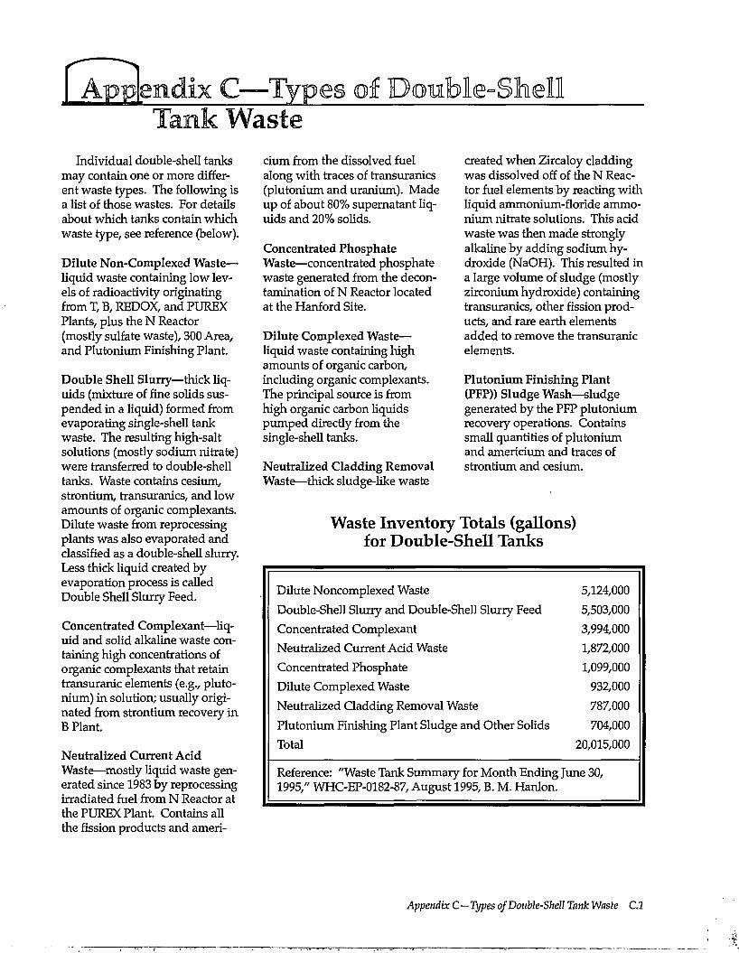
Types of Double-Shell
Individual double-shell tanks may contain one or more different waste types. The following is a list of those wastes. For details about which tanks contain which waste type, see reference (below).
Dilute Non-Complexed Waste— liquid waste containing low levels of radioactivity originating from T, B, REDOX, and PUREX Plants, plus the N Reactor (mostly sulfate waste), 300 Area, and Plutonium Finishing Plant.
Double Shell Slurry—thick liquids (mixture of fine solids suspended in a liquid) formed from evaporating single-shell tank waste. The resulting high-salt solutions (mostly sodium nitrate) were transferred to double-shell tanks. Waste contains cesium, strontium, transuranics, and low amounts of organic complexants. Dilute waste from reprocessing plants was also evaporated and classified as a double-shell slurry. Less thick liquid created by evaporation process is called Double Shell Slurry Feed.
Concentrated Complexant—liquid and solid alkaline waste containing high concentrations of organic complexants that retain transuranic elements (e.g., plutonium) in solution; usually originated from strontium recovery in B Plant.
Neutralized Current Acid Waste—mostly liquid waste generated since 1983 by reprocessing irradiated fuel from N Reactor at the PUREX Plant. Contains all the fission products and ameri-
cium from the dissolved fuel along with traces of transuranics (plutonium and uranium). Made up of about 80% supernatant liquids and 20% solids.
Concentrated Phosphate Waste—concentrated phosphate waste generated from the decontamination of N Reactor located at the Hartford Site.
Dilute Complexed Waste— liquid waste containing high amounts of organic carbon, including organic complexants. The principal source is from high organic carbon liquids pumped directly from the single-shell tanks.
Neutralized Cladding Removal Waste—thick sludge-like waste
created when Zircaloy cladding was dissolved off of the N Reactor fuel elements by reacting with liquid ammonium-floride ammonium nitrate solutions. This acid waste was then made strongly alkaline by adding sodium hydroxide (NaOH). This resulted in a large volume of sludge (mostly zirconium hydroxide) containing transuranics, other fission products, and rare earth elements added to remove the transuranic elements.
Plutonium Finishing Plant (PFP)) Sludge Wash—sludge generated by the PFP plutonium recovery operations. Contains small quantities of plutonium and americium and traces of strontium and cesium.
Waste Inventory Totals (gallons) for Double-Shell Tanks
Dilute Noncomplexed Waste 5,124,000 Double-Shell Slurry and Double-Shell Slurry Feed 5,503,000 Concentrated Complexant 3,994,000 Neutralized Current Acid Waste 1,872,000 Concentrated Phosphate 1,099,000 Dilute Complexed Waste 932,000 Neutralized Cladding Removal Waste 787,000 Plutonium Finishing Plant Sludge and Other Solids 704,000 Total 20,015,000
Reference: "Waste Tank Summary for Month Ending June 30, 1995," WHC-EP-0182-87, August 1995, B. M. Hanlon.
Appendix C—Types of Double-Shell Tank Waste C.l
Can We Make This More Useful for Yom? The writers, artists, and sponsors of this guide on technology issues of Hanford tanks tried to make it easy
to read and useful. To help us continue this effort, please take a few minutes to let us know if the guide meets your needs. Then tear out this page and mail to
Regina Lundgren Pacific Northwest Laboratory P.O.Box999,MSINK9-01 Richland, WA 99352 (509)372-6012
1. How do you use the information in this guide? Q to learn general information about the Hanford Site Q to learn about science and technology issues Q to prepare for public meetings on Hanford cleanup Q other (please explain)
2. What parts of the booklet do you use? Q history/background Q closing the tanks Q public involvement information Q safety issues Q storing waste
Q tank description Q disposal of waste Q leaks of tank waste Q retrieval of waste Q risks associated with tanks
3. Does this guide contain Q enough detail Comment:
Q too much detail Q too little detail
4. If you could change this guide to make it more readable and useful to you, what would you change?
5. What is your affiliation? Q Hanford Site contractor Q State agency Q public interest group Q member of Native American Nation Q university Q other
Q DOE Q Federal agency Q member of the public Q local government Q industry
6. Other Comments
Thank You!


![rss~'Dce- a.,]) R.e-1ssu1](https://img.pdfslide.us/doc/110x75/5f8f63b590e69168e30c6c5c/rssdce-a-re-1ssu1.jpg)