Embed Size (px)
Citation preview

Two-Way Development Update
Presented byMicrocom Design, Inc.
April 2020
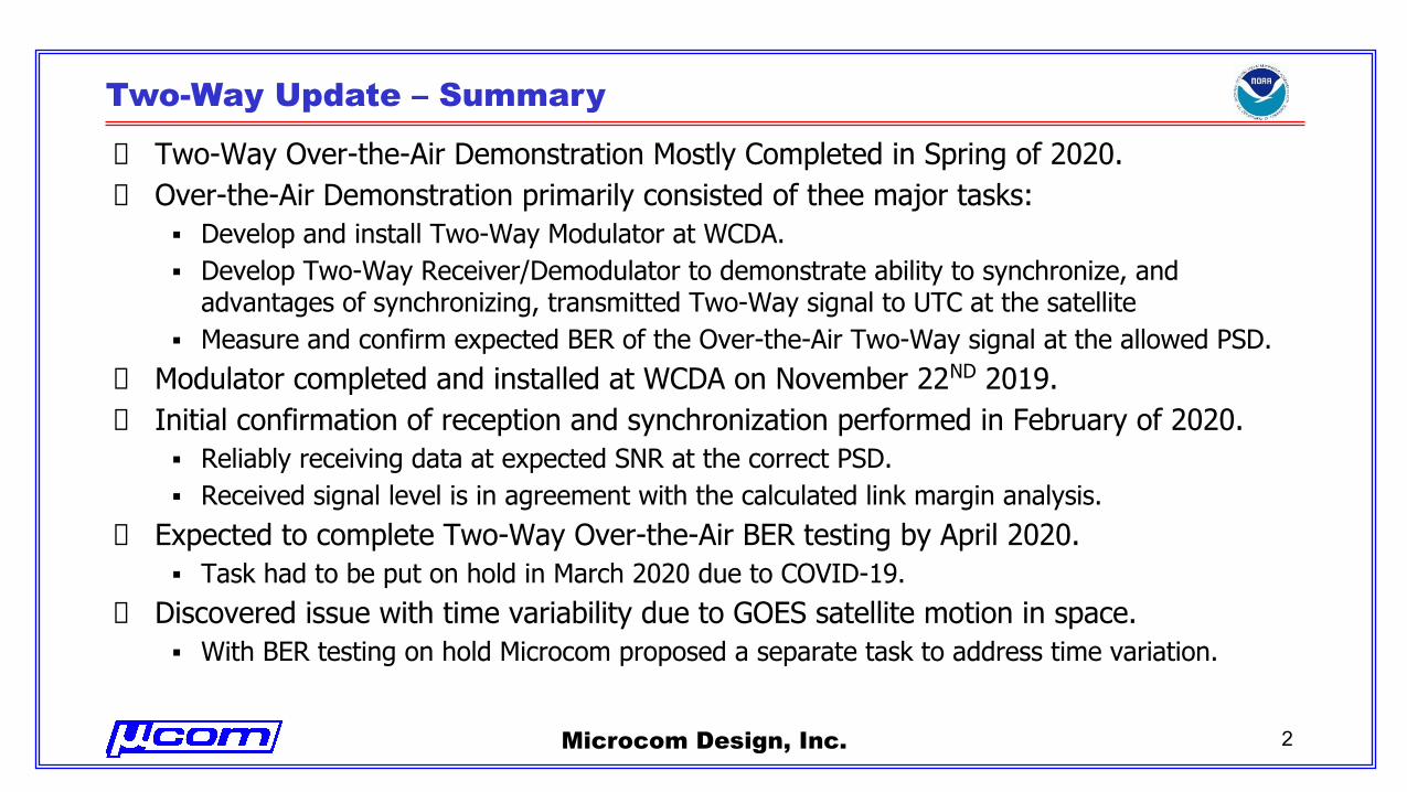
Two-Way Update – Summary
Two-Way Over-the-Air Demonstration Mostly Completed in Spring of 2020.Over-the-Air Demonstration primarily consisted of thee major tasks:▪ Develop and install Two-Way Modulator at WCDA.▪ Develop Two-Way Receiver/Demodulator to demonstrate ability to synchronize, and
advantages of synchronizing, transmitted Two-Way signal to UTC at the satellite▪ Measure and confirm expected BER of the Over-the-Air Two-Way signal at the allowed PSD.
Modulator completed and installed at WCDA on November 22ND 2019.Initial confirmation of reception and synchronization performed in February of 2020.▪ Reliably receiving data at expected SNR at the correct PSD.▪ Received signal level is in agreement with the calculated link margin analysis.
Expected to complete Two-Way Over-the-Air BER testing by April 2020.▪ Task had to be put on hold in March 2020 due to COVID-19.
Discovered issue with time variability due to GOES satellite motion in space.▪ With BER testing on hold Microcom proposed a separate task to address time variation.
Microcom Design, Inc. 2
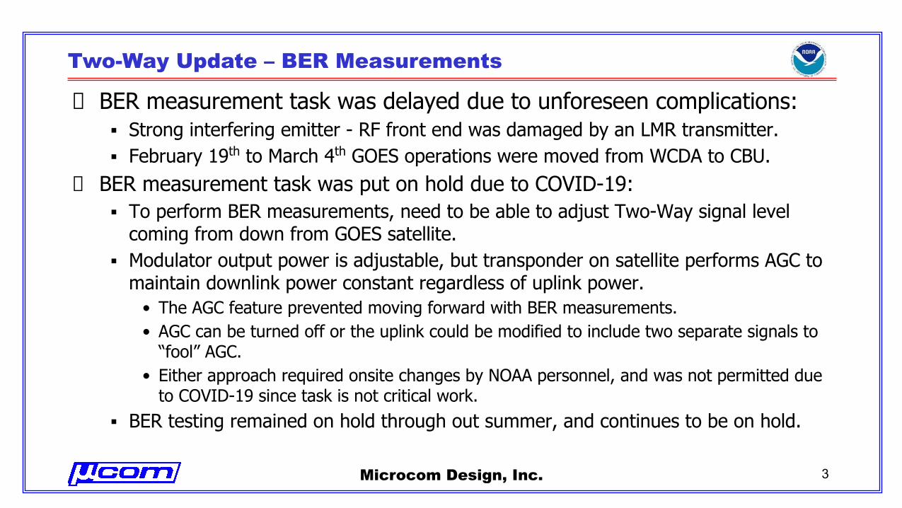
Two-Way Update – BER Measurements
BER measurement task was delayed due to unforeseen complications:▪ Strong interfering emitter - RF front end was damaged by an LMR transmitter.▪ February 19th to March 4th GOES operations were moved from WCDA to CBU.
BER measurement task was put on hold due to COVID-19:▪ To perform BER measurements, need to be able to adjust Two-Way signal level
coming from down from GOES satellite.▪ Modulator output power is adjustable, but transponder on satellite performs AGC to
maintain downlink power constant regardless of uplink power.• The AGC feature prevented moving forward with BER measurements.• AGC can be turned off or the uplink could be modified to include two separate signals to
“fool” AGC.• Either approach required onsite changes by NOAA personnel, and was not permitted due
to COVID-19 since task is not critical work.▪ BER testing remained on hold through out summer, and continues to be on hold.
Microcom Design, Inc. 3
Two-Way Update – Satellite Movement Task
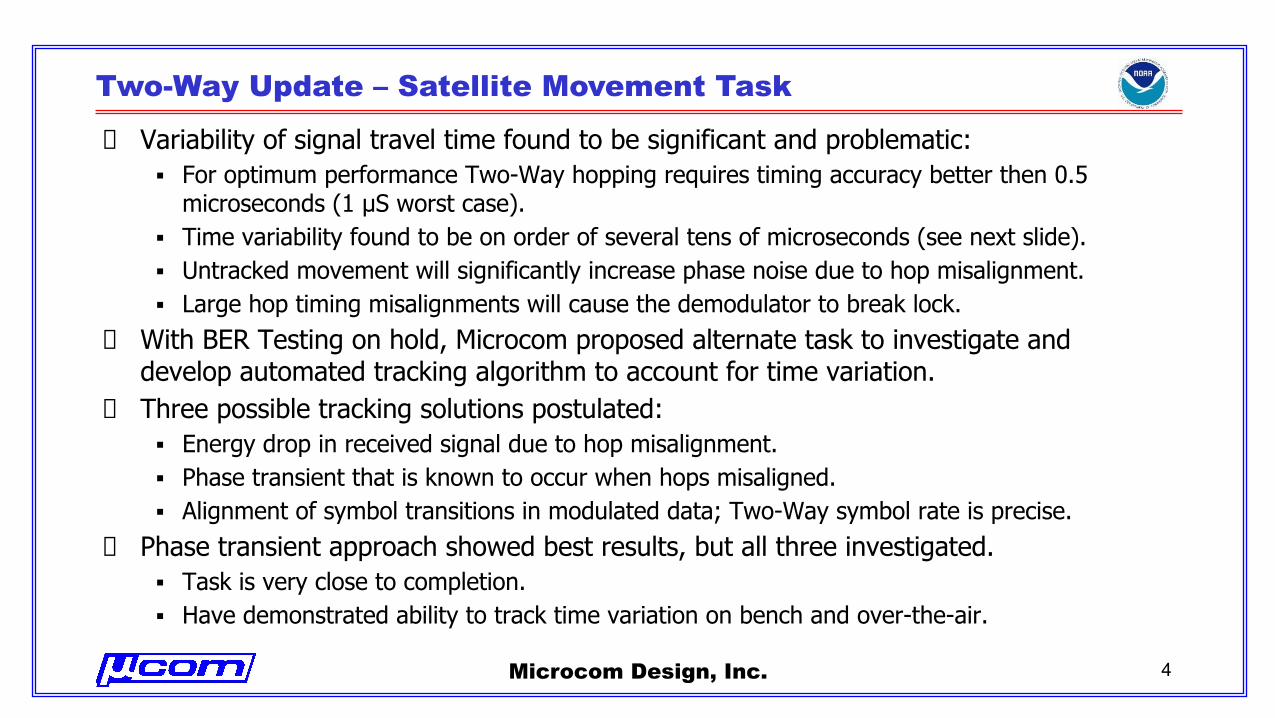
Variability of signal travel time found to be significant and problematic:▪ For optimum performance Two-Way hopping requires timing accuracy better then 0.5
microseconds (1 µS worst case).▪ Time variability found to be on order of several tens of microseconds (see next slide).▪ Untracked movement will significantly increase phase noise due to hop misalignment.▪ Large hop timing misalignments will cause the demodulator to break lock.
With BER Testing on hold, Microcom proposed alternate task to investigate and develop automated tracking algorithm to account for time variation.Three possible tracking solutions postulated:▪ Energy drop in received signal due to hop misalignment.▪ Phase transient that is known to occur when hops misaligned.▪ Alignment of symbol transitions in modulated data; Two-Way symbol rate is precise.
Phase transient approach showed best results, but all three investigated.▪ Task is very close to completion.▪ Have demonstrated ability to track time variation on bench and over-the-air.
Microcom Design, Inc. 4
Two-Way Update – Satellite Movement
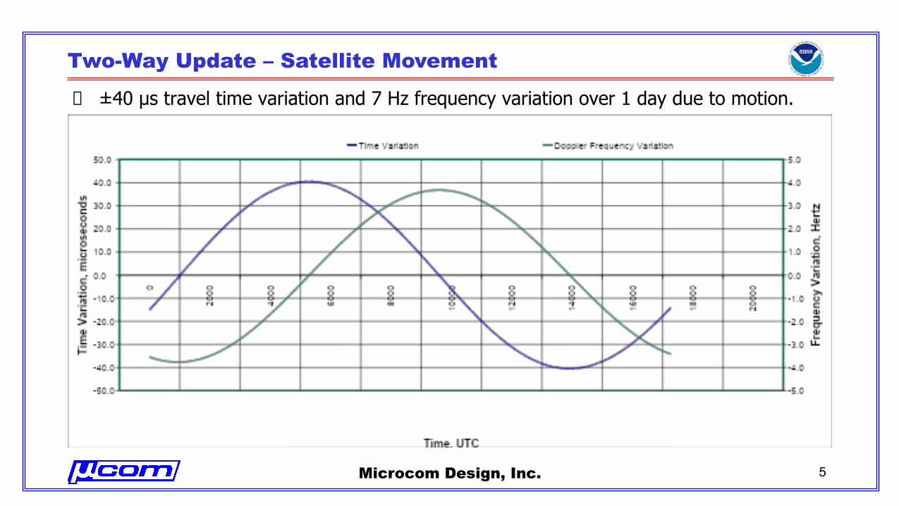
±40 μs travel time variation and 7 Hz frequency variation over 1 day due to motion.
Microcom Design, Inc. 5
Two-Way Update – Energy Drop Misalignment Investigation
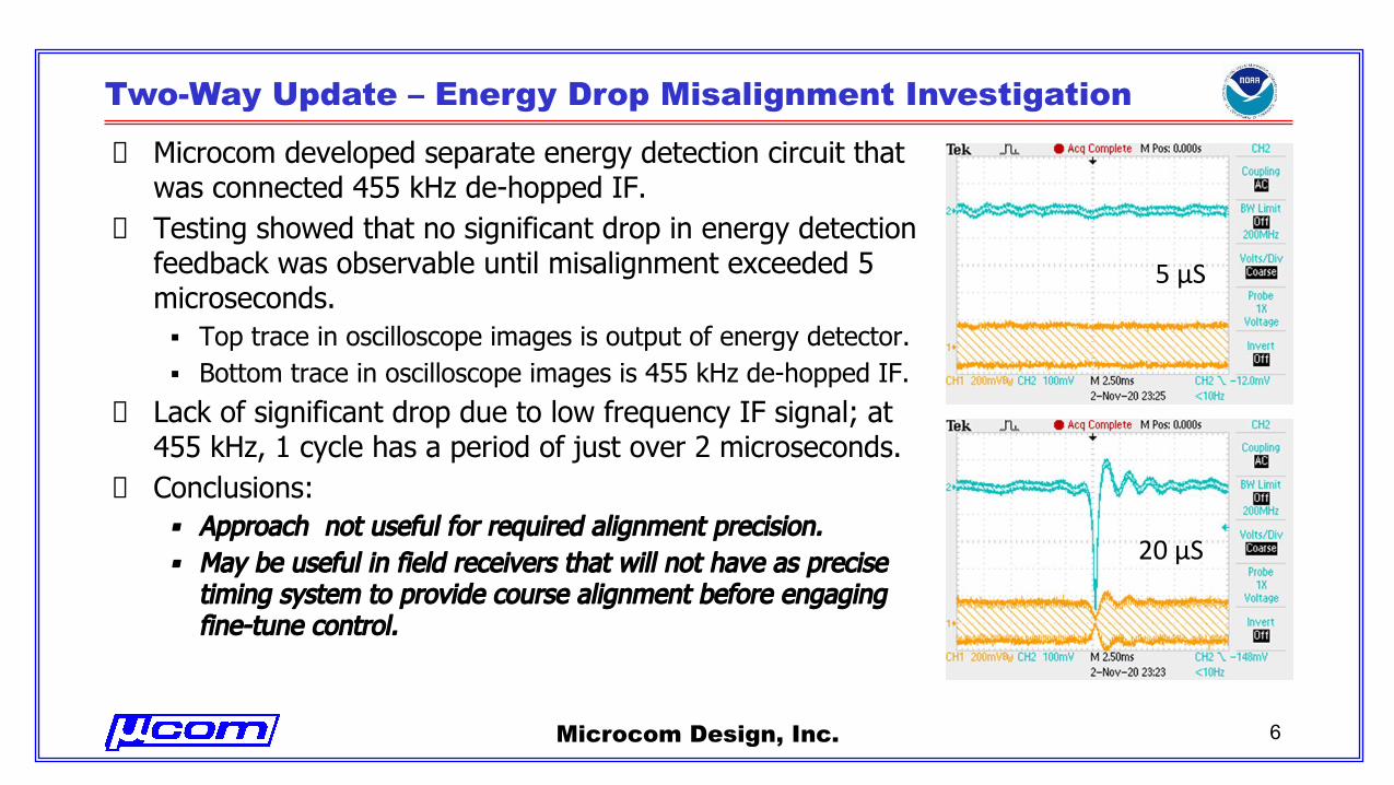
Microcom developed separate energy detection circuit that was connected 455 kHz de-hopped IF.Testing showed that no significant drop in energy detection feedback was observable until misalignment exceeded 5 microseconds.▪ Top trace in oscilloscope images is output of energy detector.▪ Bottom trace in oscilloscope images is 455 kHz de-hopped IF.
Lack of significant drop due to low frequency IF signal; at 455 kHz, 1 cycle has a period of just over 2 microseconds. Conclusions: ▪ Approach not useful for required alignment precision.▪ May be useful in field receivers that will not have as precise
timing system to provide course alignment before engaging fine-tune control.
Microcom Design, Inc. 6
5 µS
20 µS
Two-Way Update – Symbol Transition Initial Investigation
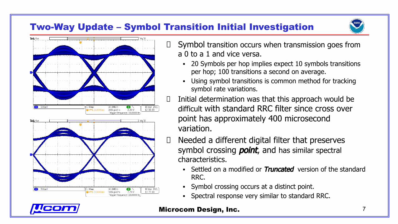
Symbol transition occurs when transmission goes from a 0 to a 1 and vice versa. ▪ 20 Symbols per hop implies expect 10 symbols transitions
per hop; 100 transitions a second on average.▪ Using symbol transitions is common method for tracking
symbol rate variations.
Initial determination was that this approach would be difficult with standard RRC filter since cross over point has approximately 400 microsecond variation.Needed a different digital filter that preserves symbol crossing point, and has similar spectral characteristics. ▪ Settled on a modified or Truncated version of the standard
RRC.▪ Symbol crossing occurs at a distinct point.▪ Spectral response very similar to standard RRC.
Microcom Design, Inc. 7
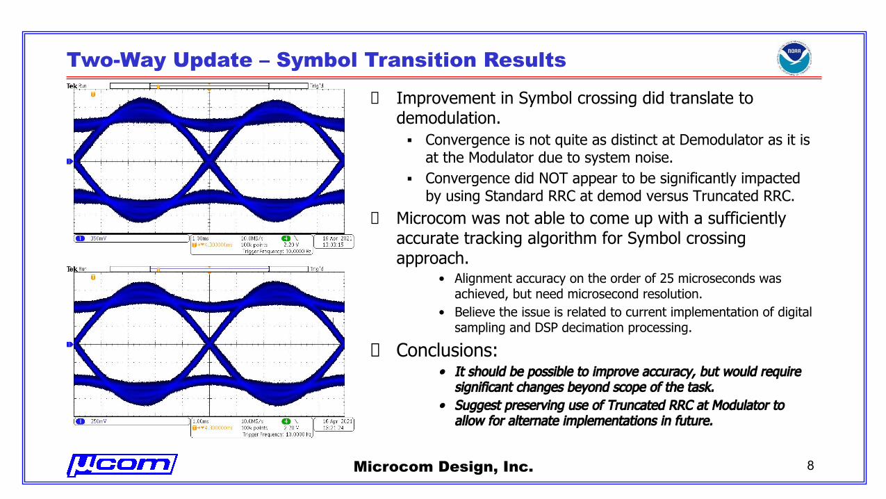
Two-Way Update – Symbol Transition Results
Improvement in Symbol crossing did translate to demodulation.▪ Convergence is not quite as distinct at Demodulator as it is
at the Modulator due to system noise.▪ Convergence did NOT appear to be significantly impacted
by using Standard RRC at demod versus Truncated RRC.Microcom was not able to come up with a sufficiently accurate tracking algorithm for Symbol crossing approach.
• Alignment accuracy on the order of 25 microseconds was achieved, but need microsecond resolution.
• Believe the issue is related to current implementation of digital sampling and DSP decimation processing.
Conclusions: • It should be possible to improve accuracy, but would require
significant changes beyond scope of the task.• Suggest preserving use of Truncated RRC at Modulator to
allow for alternate implementations in future.
Microcom Design, Inc. 8
Two-Way Update – Symbol Transition – RRC Comparison Mod
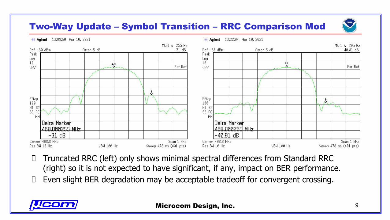
Truncated RRC (left) only shows minimal spectral differences from Standard RRC (right) so it is not expected to have significant, if any, impact on BER performance.Even slight BER degradation may be acceptable tradeoff for convergent crossing.
Microcom Design, Inc. 9
Two-Way Update – Symbol Transition – RRC Comparison Demod
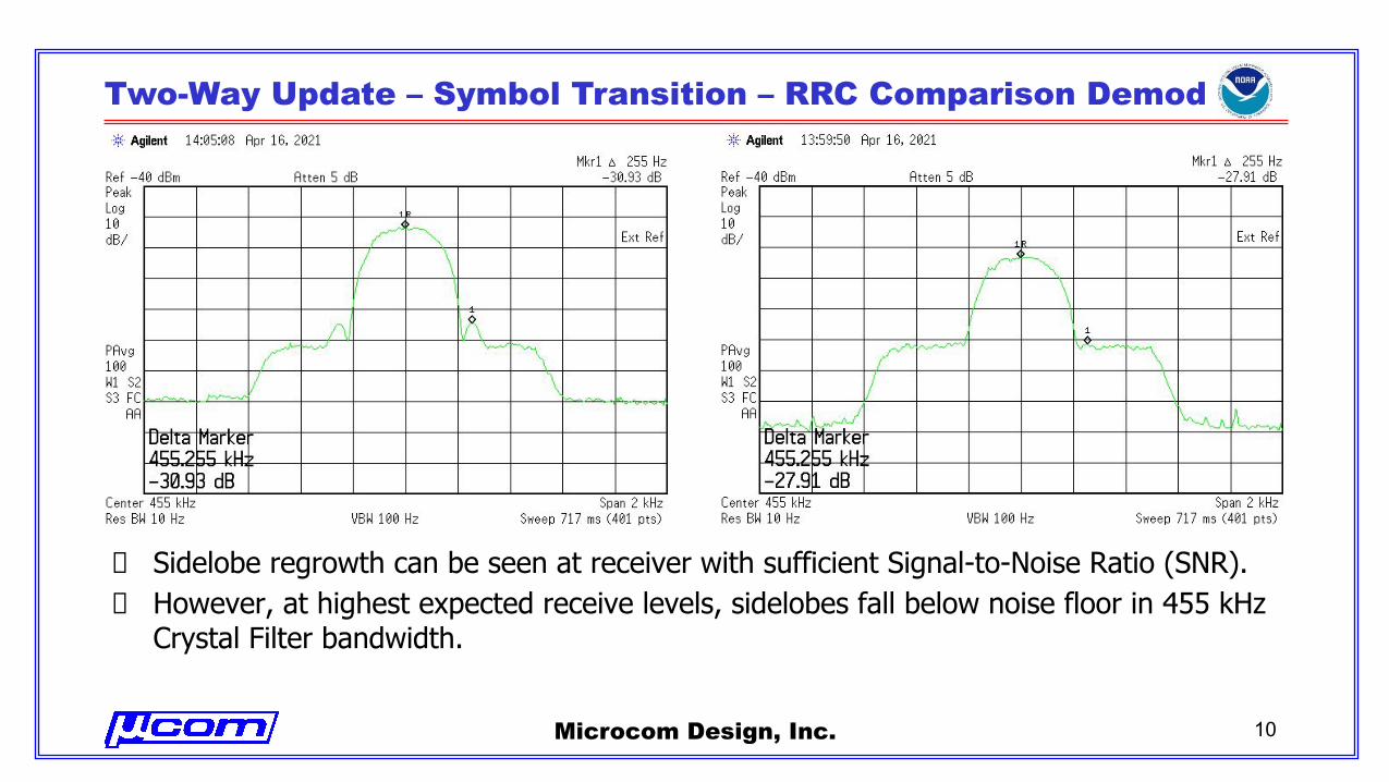
Sidelobe regrowth can be seen at receiver with sufficient Signal-to-Noise Ratio (SNR). However, at highest expected receive levels, sidelobes fall below noise floor in 455 kHz Crystal Filter bandwidth.
Microcom Design, Inc. 10
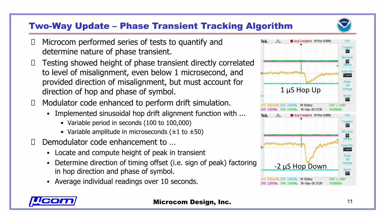
Two-Way Update – Phase Transient Tracking Algorithm
Microcom performed series of tests to quantify and determine nature of phase transient.Testing showed height of phase transient directly correlated to level of misalignment, even below 1 microsecond, and provided direction of misalignment, but must account for direction of hop and phase of symbol.Modulator code enhanced to perform drift simulation.▪ Implemented sinusoidal hop drift alignment function with ...
• Variable period in seconds (100 to 100,000)• Variable amplitude in microseconds (±1 to ±50)
Demodulator code enhancement to … ▪ Locate and compute height of peak in transient▪ Determine direction of timing offset (i.e. sign of peak) factoring
in hop direction and phase of symbol.▪ Average individual readings over 10 seconds.
Microcom Design, Inc. 11
1 µS Hop Up
-2 µS Hop Down
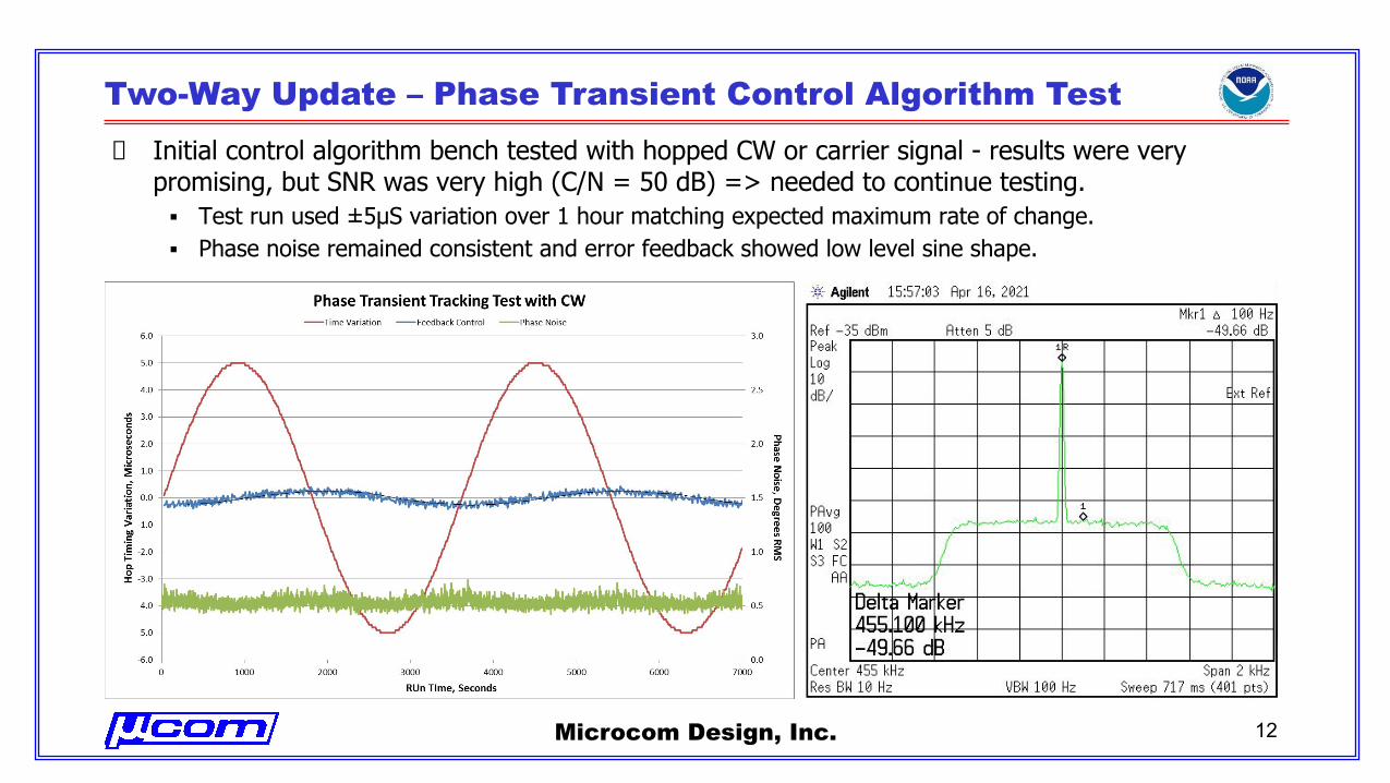
Two-Way Update – Phase Transient Control Algorithm Test
Initial control algorithm bench tested with hopped CW or carrier signal - results were very promising, but SNR was very high (C/N = 50 dB) => needed to continue testing.▪ Test run used ±5µS variation over 1 hour matching expected maximum rate of change.▪ Phase noise remained consistent and error feedback showed low level sine shape.
Microcom Design, Inc. 12
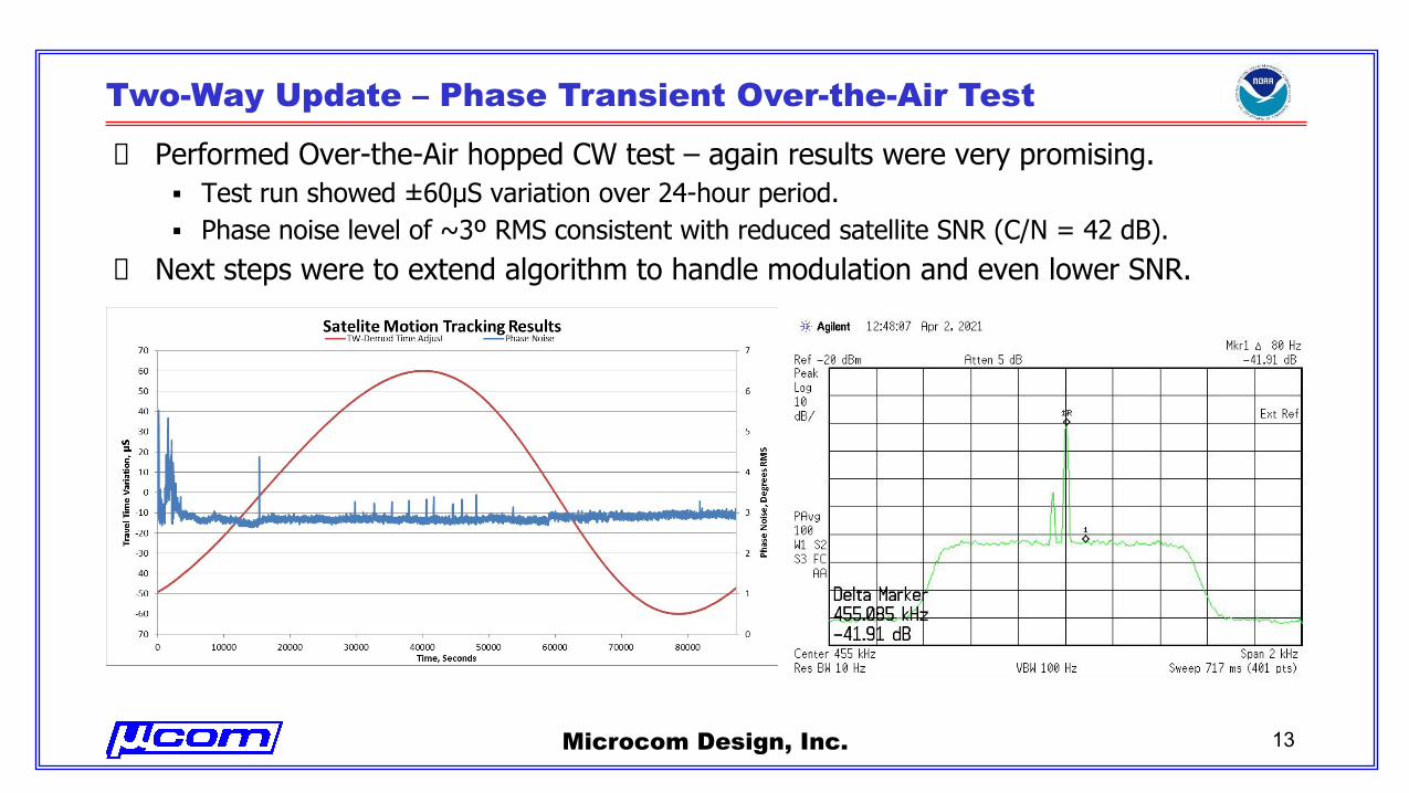
Two-Way Update – Phase Transient Over-the-Air Test
Performed Over-the-Air hopped CW test – again results were very promising.▪ Test run showed ±60µS variation over 24-hour period.▪ Phase noise level of ~3º RMS consistent with reduced satellite SNR (C/N = 42 dB).
Next steps were to extend algorithm to handle modulation and even lower SNR.
Microcom Design, Inc. 13
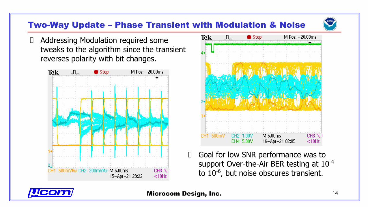
Two-Way Update – Phase Transient with Modulation & Noise
Addressing Modulation required some tweaks to the algorithm since the transient reverses polarity with bit changes.
Microcom Design, Inc. 14
Goal for low SNR performance was to support Over-the-Air BER testing at 10-4 to 10-6, but noise obscures transient.
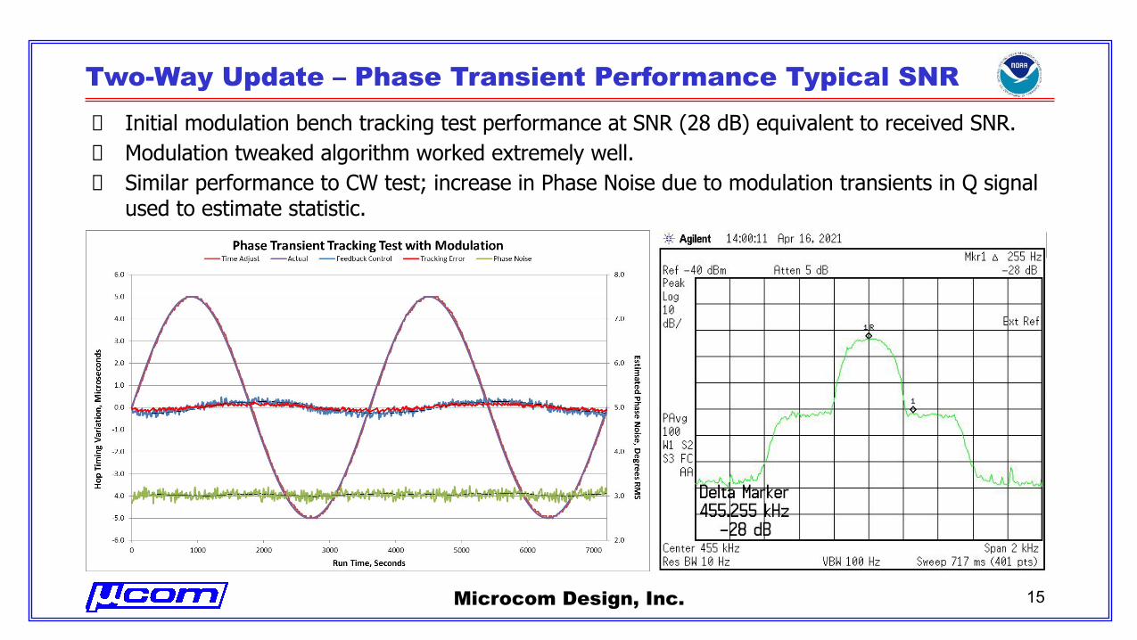
Two-Way Update – Phase Transient Performance Typical SNR
Initial modulation bench tracking test performance at SNR (28 dB) equivalent to received SNR.Modulation tweaked algorithm worked extremely well.Similar performance to CW test; increase in Phase Noise due to modulation transients in Q signal used to estimate statistic.
Microcom Design, Inc. 15
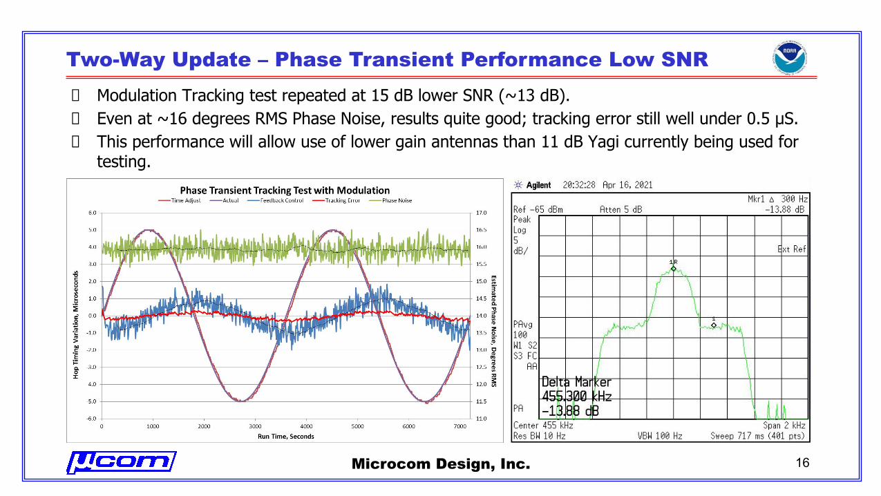
Two-Way Update – Phase Transient Performance Low SNR
Modulation Tracking test repeated at 15 dB lower SNR (~13 dB).Even at ~16 degrees RMS Phase Noise, results quite good; tracking error still well under 0.5 µS.This performance will allow use of lower gain antennas than 11 dB Yagi currently being used for testing.
Microcom Design, Inc. 16
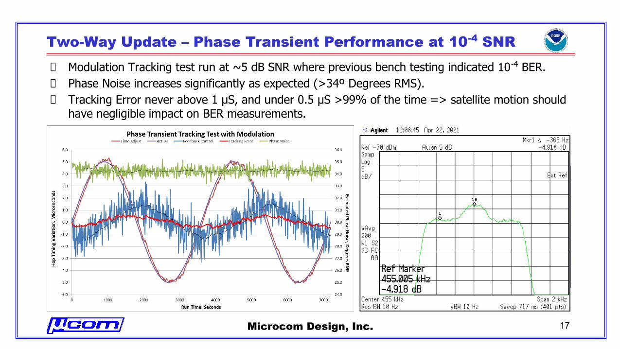
Two-Way Update – Phase Transient Performance at 10-4 SNR
Modulation Tracking test run at ~5 dB SNR where previous bench testing indicated 10-4 BER.Phase Noise increases significantly as expected (>34º Degrees RMS).Tracking Error never above 1 µS, and under 0.5 µS >99% of the time => satellite motion should have negligible impact on BER measurements.
Microcom Design, Inc. 17
Two-Way Update – Summary, Conclusion & Next Steps
Summary ▪ All 3 approaches (energy drop, symbol crossing, and phase transient) investigated
may ultimately prove useful.▪ Satellite motion confirmed and tracked on bench and over-the-air with phase
transient implementation.
Conclusion▪ Phase Transient Tracking Algorithm meets Objective of 1µS Alignment.▪ Tracking Algorithm will support final BER Testing.
Next Steps: Finish Over-the-Air Testing once power control is addressed.▪ First confirm modulation tracking over-the-air at various SNRs.▪ Perform BER measurements with Standard and Truncated RRC at Modulator.▪ Prepare and submit final Over-the-Air Testing report.
Microcom Design, Inc. 18