Embed Size (px)
Citation preview
Two types of single-beam deflectionand asymmetric transmission in photonicstructures without interface corrugationsANDRIY E. SEREBRYANNIKOV,1,* EVRIM COLAK,2 THORE MAGATH,3 AND EKMEL OZBAY4
1Adam Mickiewicz University, Faculty of Physics, 61-614 Poznan, Poland2Ankara University, Electrical Engineering Department, Golbasi, 06830 Ankara, Turkey3Panasonic Electron Devices Europe GmbH, European Technology Center, D-21337 Luneburg, Germany4Bilkent University, Nanotechnology Research Center–NANOTAM, 06800 Ankara, Turkey*Corresponding author: [email protected]
Received 15 August 2016; revised 14 October 2016; accepted 31 October 2016; posted 1 November 2016 (Doc. ID 273334);published 28 November 2016
We study single-beam deflection and asymmetry in transmission, two aspects of the same phenomenon thatappear in the topologically simple, nonsymmetric, photonic crystal (PhC)-based structures without corrugationsat the interfaces. Strong diffractions enabling efficient blazing, i.e., redistribution of the incident wave energy infavor of the desired higher diffraction order(s), can be achieved owing to the defect-like layer(s) embedded in aregular slab of PhC. The main features, together with the peculiarities of the two basic transmission types andrelevant coupling and deflection scenarios, are discussed, for one of which a part of the PhC works in theevanescent-wave regime. Performances are suggested, in which efficient single-beam deflection and asymmetryin transmission can be obtained even when the irregular layer is deeply embedded. More than 97% of the incidentwave energy can be converted into a single deflected beam that is associated with the first negative diffractionorder, even though the entire structure is nonsymmetric and the diffractive element is located at some distancefrom the incidence interface. © 2016 Optical Society of America
OCIS codes: (050.1940) Diffraction; (050.2770) Gratings; (050.5298) Photonic crystals; (120.7000) Transmission.
https://doi.org/10.1364/JOSAA.33.002450
1. INTRODUCTION
Advanced functionality and operation regimes can be realizedin photonic structures made of linear, isotropic, passive materi-als, in which the effects of different periodicities are properlycombined. Among them, one should mention those knownas photonic crystal (PhC) gratings [1–5]. Initially, PhC gratingswere proposed for the reflection mode [1,6] and later for thetransmission mode [3,7]. The interest in PhC gratings has beengrowing in the connection with diffraction-inspired asymmet-ric transmission [2–5] and locations of frequency-domainthresholds for higher diffraction orders [7], which are unusualcompared to the classical grating theory [8]. To obtain theseregimes, the spatial inversion symmetry must be broken.The structures for asymmetric transmission are Lorentzreciprocal and, thus, provide regimes of directional selectivitythat are distinguished from those achievable in the nonrecip-rocal structures with the aid of anisotropic materials (see[9,10]). Different regimes of diffraction-inspired asymmetrictransmission have also been demonstrated in nonsymmetricgratings made of ultralow-index natural materials [11,12],
nonsymmetric metamaterial gratings [13,14], and finite-thick-ness metallic slabs with branched slots creating different periodsat two interfaces [15].
The role and scenarios of suppression of the zero order forwideband asymmetric transmission have been studied [2,4].Indeed, for any grating with broken structural symmetry,forward (further indicated by → ) and backward (indicatedby ← ) transmission is exactly the same for the zero order,i.e., t0 � t→0 � t←0 due to the reciprocity, but it is different(in the general case) for higher orders, i.e., t→m ≠ t←m whenjmj > 0. Thanks to the latter, we have T→ ≠ T←, whereT→ and T← mean the forward and backward transmittancesthat include the contributions of all propagating orders. Ifdispersion block coupling of the zero order to a Floquet–Bloch wave of PhC and different corrugations are used atthe front-side and the back-side interfaces so coupling is pos-sible only at one of the interfaces, the most interesting regime ofasymmetric transmission (known as unidirectional transmission)can be realized due to the common effects of diffraction anddispersion. For this regime, transmission is nonzero only for
2450 Vol. 33, No. 12 / December 2016 / Journal of the Optical Society of America A Research Article
1084-7529/16/122450-09 Journal © 2016 Optical Society of America
one of the two opposite incidence directions. Additionally,asymmetry in transmission can be achieved owing to the ori-entation of the interfaces, such as in PhC prisms [16,17], or theuse of two orthogonal polarizations, as is done for coupledmetasurfaces built of subwavelength resonators [18,19].Further examples of asymmetric effects include those relatedto transmission through a subwavelength slit that can be en-hanced by the effect of surface waves [20,21], propagationin a waveguide in a PhC slab [22,23], and transmission throughgraded-index (chirped) PhCs [24]. It can also be obtained byusing structures with parity-time symmetry [25,26]. Hence,asymmetry in transmission is a very general phenomenon thatmay enable various operation regimes.
Single-beam unidirectional deflection [4], a regime of asym-metric transmission inspired by diffractions, has been a focus ofinterest also because of its connection with the classical problemof blazing [27], i.e., the redistribution of the incident wave en-ergy in favor of one of higher diffraction orders. While echelettereflection mode gratings are known as the classical structures thatenable blazing, alternative structures have later been proposed,e.g., those based on binary gratings with several ridges andgrooves per period and complex gratings with a period contain-ing multiple subwavelength holes and pillars [28–30]. Today,blazing and deflection remain important for the further develop-ment of advanced photonic and microwave components and de-vices. In particular, Huygens metasurfaces have recently beensuggested that allow one to obtain single-beam deflection inthe reflection-free regime [31,32]. Similar regimes are highly de-manded for PhC-based platforms, which are widely used in pho-tonic circuitry. Moreover, the richness of the dispersion typesachievable in one PhC provides the principal possibility of multi-functionality, i.e., different functions can be realized within dif-ferent frequency ranges in one structure. Until now, single-beamdeflection has been studied in PhC-based structures with a cor-rugated interface that imposes significant restrictions on the re-sulting design. At the same time, the recent results on dual-beamunidirectional splitting, another regime inspired by diffractions,indicate the possibility of strong diffractions in photonic struc-tures without a corrugated interface [33].
In this paper, our hypothesis about the possibility of strongsingle-beam deflection and blazing and related asymmetrictransmission in topologically simple PhC-based structureswithout interface corrugations, which may involve evanes-cent-wave components, is validated and the generality of thebasic effects is demonstrated. The required diffractions are ob-tained in the proposed approach due to the irregular layer of therods that has a different period than the layers belonging to theregular part of PhC, into which the irregular layer is embedded.Its location is chosen so the entire structure is nonsymmetric,i.e., the necessary condition of asymmetric transmission is ful-filled. The results are presented for well-selected structures thatprovide illustrative results at different locations of the irregularlayer with respect to the interfaces. The main attention will bepaid to the case when a sole irregular layer is embedded in aregular PhC. Such defect-type irregular layers are expectedto enable deflection in one frequency range and to be utilizedfor the realization of another functionality, e.g., defect-modewave guiding [34], in another frequency range but in the same
structure. Most of the presented results are related to thetransmittance; a brief comparison with the dispersion resultsis also included. Transmission results are obtained with theaid of the coupled integral equation technique [35], whileCST Microwave Studio [36], a full-wave software based onthe finite integration method, and a self-made post-processingcode were used to compute the dispersion.
2. GEOMETRY AND OPERATION PRINCIPLES
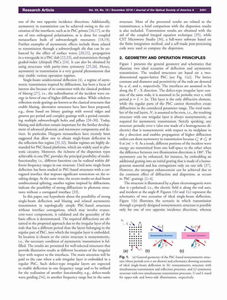
Figure 1 presents the general geometry and schematics thatillustrate two ideal scenarios of deflection and asymmetrictransmission. The studied structures are based on a two-dimensional square-lattice PhC [see Fig. 1(a)]. The latticeconstant and diameter and permittivity of the rods are denotedby a, d , and ε, respectively. The interfaces are assumed to bealong the Γ − X direction. The defect-type irregular layer con-sists of the same rods; it is assumed to be periodic over x, withperiod p � L � 2a. This layer is the only diffractive element,while the regular parts of the PhC cannot themselves creatediffractions in the considered parameter range. The total num-ber of the rod layers,N , is assumed to be even, i.e., the resultingstructure with one irregular layer is always nonsymmetric, asrequired for asymmetric transmission. Strictly speaking, anystructure periodic over x (also one made of a homogeneous di-electric) that is nonsymmetric with respect to its midplane inthe y direction and enables propagation of higher diffractionorders can show asymmetry in transmission because t→m ≠ t←m ≠0 at jmj > 0. As a result, different portions of the incident waveenergy are transmitted from one half-space to the other whenthe difference between two illumination directions is 180°. Theasymmetry can be enhanced, for instance, by embedding anadditional grating into an initial grating that is made of a homo-geneous material and has corrugations only on one side [37].However, the strongest enhancement can be achieved due tothe common effect of diffraction and dispersion, as occursin PhC gratings [2–4].
The structure is illuminated by a plane electromagnetic wavethat is s-polarized, i.e., the electric field is along the rod axes,and incident at the angle θ. Figures 1(b) and 1(c) represent theschematics of two scenarios of ideal single-beam deflection.Figure 1(b) illustrates the scenario in which transmissionthrough a properly designed nonsymmetric structure is possibleonly for one of two opposite incidence directions, whereas
Fig. 1. (a) General geometry of the PhC-based nonsymmetric struc-ture (three periods over x are shown) and schematics showing scenariosof ideal single-beam deflection in (b) nonsymmetric structure withsimultaneous transmission and reflection processes, and (c) symmetricstructure with two simultaneous transmission processes. U and L standfor upper-side and lower-side illumination, respectively.
Research Article Vol. 33, No. 12 / December 2016 / Journal of the Optical Society of America A 2451
specular reflection occurs for the second direction. In [4], thisscenario has been discussed for PhC gratings with nondeepone-side interface corrugations. However, it is not clear yethow a similar scenario can be realized when the diffractiveelement is located inside the structure.
According to [4], the main role of dispersion is to block cou-pling and transmission for an undesired range of the tangentialwavenumber and provide coupling for a desired one. In linewith Lorentz reciprocity, it can even be realized only due tothe effect of diffractions. In contrast with the previous case,it can be done only in a narrow band because of the absenceof the wideband blocking effect of dispersion (see [4]).
An important feature illustrated in Fig. 1(b) is that thedirections of the outgoing beams for upper-side and lower-side incidence do not coincide in the general case, i.e.,φ ≠ θ, where
φ � ϕ−1 � arcsin�sin θ − 2π∕�kL�� (1)
is the diffraction angle for the order m � −1 [8]; k � ω∕c isfree-space wave number. Thus, two simultaneous processes canbe independent, at least if the deflection is ideal. The only ex-ception is related to the case when θ � φ, i.e., sin θ � π∕�kL�.Then, two beams are combined into one. For comparison, inFig. 1(c), the ideal blazing is schematically shown for a sym-metric structure, in which it may occur for both opposite in-cidence directions. Even in this case, two processes can beindependent, provided the deflection is ideal. This regime issimilar to one of those studied in [20] for metallic gratings withnonsymmetric corrugations and a subwavelength slit. From theabove given reasons, the advantages of ideal deflection are ob-vious. In this paper, consideration is restricted to the scenario inFig. 1(b) and similar but nonideal deflection scenarios.
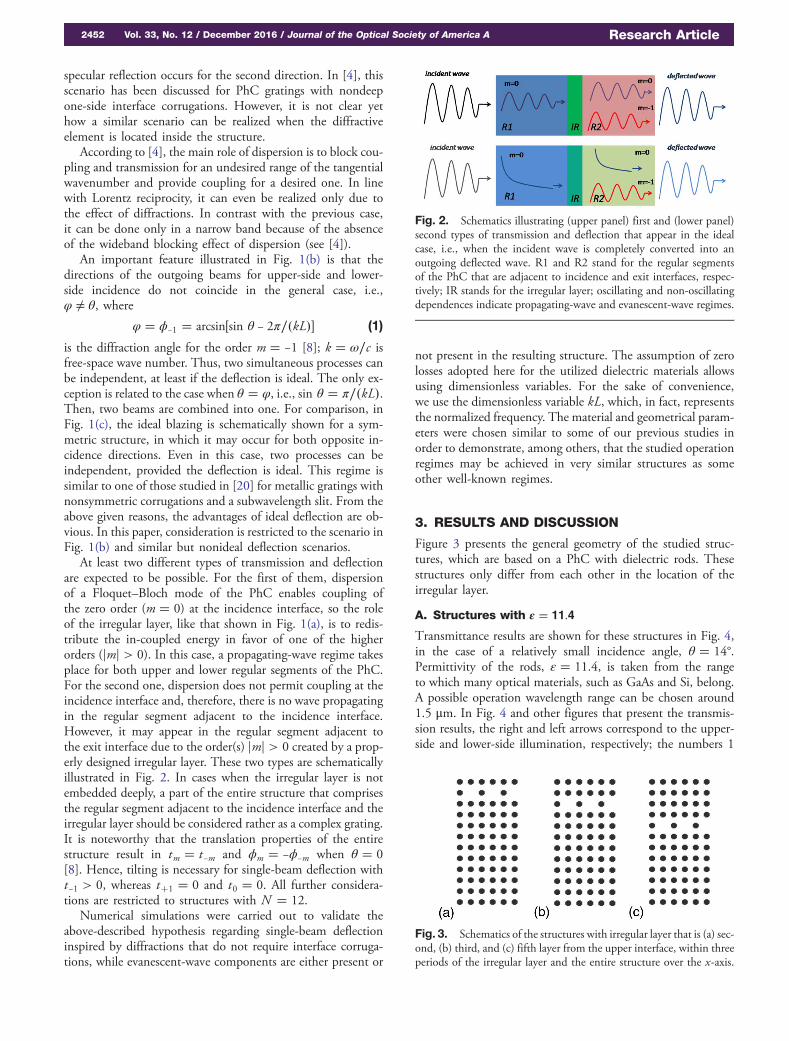
At least two different types of transmission and deflectionare expected to be possible. For the first of them, dispersionof a Floquet–Bloch mode of the PhC enables coupling ofthe zero order (m � 0) at the incidence interface, so the roleof the irregular layer, like that shown in Fig. 1(a), is to redis-tribute the in-coupled energy in favor of one of the higherorders (jmj > 0). In this case, a propagating-wave regime takesplace for both upper and lower regular segments of the PhC.For the second one, dispersion does not permit coupling at theincidence interface and, therefore, there is no wave propagatingin the regular segment adjacent to the incidence interface.However, it may appear in the regular segment adjacent tothe exit interface due to the order(s) jmj > 0 created by a prop-erly designed irregular layer. These two types are schematicallyillustrated in Fig. 2. In cases when the irregular layer is notembedded deeply, a part of the entire structure that comprisesthe regular segment adjacent to the incidence interface and theirregular layer should be considered rather as a complex grating.It is noteworthy that the translation properties of the entirestructure result in tm � t−m and ϕm � −ϕ−m when θ � 0[8]. Hence, tilting is necessary for single-beam deflection witht−1 > 0, whereas t�1 � 0 and t0 � 0. All further considera-tions are restricted to structures with N � 12.
Numerical simulations were carried out to validate theabove-described hypothesis regarding single-beam deflectioninspired by diffractions that do not require interface corruga-tions, while evanescent-wave components are either present or
not present in the resulting structure. The assumption of zerolosses adopted here for the utilized dielectric materials allowsusing dimensionless variables. For the sake of convenience,we use the dimensionless variable kL, which, in fact, representsthe normalized frequency. The material and geometrical param-eters were chosen similar to some of our previous studies inorder to demonstrate, among others, that the studied operationregimes may be achieved in very similar structures as someother well-known regimes.
3. RESULTS AND DISCUSSION
Figure 3 presents the general geometry of the studied struc-tures, which are based on a PhC with dielectric rods. Thesestructures only differ from each other in the location of theirregular layer.
A. Structures with ε � 11.4
Transmittance results are shown for these structures in Fig. 4,in the case of a relatively small incidence angle, θ � 14°.Permittivity of the rods, ε � 11.4, is taken from the rangeto which many optical materials, such as GaAs and Si, belong.A possible operation wavelength range can be chosen around1.5 μm. In Fig. 4 and other figures that present the transmis-sion results, the right and left arrows correspond to the upper-side and lower-side illumination, respectively; the numbers 1
Fig. 2. Schematics illustrating (upper panel) first and (lower panel)second types of transmission and deflection that appear in the idealcase, i.e., when the incident wave is completely converted into anoutgoing deflected wave. R1 and R2 stand for the regular segmentsof the PhC that are adjacent to incidence and exit interfaces, respec-tively; IR stands for the irregular layer; oscillating and non-oscillatingdependences indicate propagating-wave and evanescent-wave regimes.
Fig. 3. Schematics of the structures with irregular layer that is (a) sec-ond, (b) third, and (c) fifth layer from the upper interface, within threeperiods of the irregular layer and the entire structure over the x-axis.
2452 Vol. 33, No. 12 / December 2016 / Journal of the Optical Society of America A Research Article
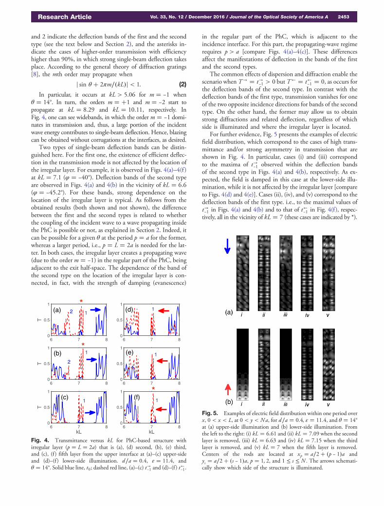
and 2 indicate the deflection bands of the first and the secondtype (see the text below and Section 2), and the asterisks in-dicate the cases of higher-order transmission with efficiencyhigher than 90%, in which strong single-beam deflection takesplace. According to the general theory of diffraction gratings[8], the mth order may propagate when
j sin θ� 2πm∕�kL�j < 1: (2)
In particular, it occurs at kL > 5.06 for m � −1 whenθ � 14°. In turn, the orders m � �1 and m � −2 start topropagate at kL � 8.29 and kL � 10.11, respectively. InFig. 4, one can see widebands, in which the order m � −1 domi-nates in transmission and, thus, a large portion of the incidentwave energy contributes to single-beam deflection. Hence, blazingcan be obtained without corrugations at the interfaces, as desired.
Two types of single-beam deflection bands can be distin-guished here. For the first one, the existence of efficient deflec-tion in the transmission mode is not affected by the location ofthe irregular layer. For example, it is observed in Figs. 4(a)–4(f )at kL � 7.1 (φ � −40°). Deflection bands of the second typeare observed in Figs. 4(a) and 4(b) in the vicinity of kL � 6.6(φ � −45.2°). For these bands, strong dependence on thelocation of the irregular layer is typical. As follows from theobtained results (both shown and not shown), the differencebetween the first and the second types is related to whetherthe coupling of the incident wave to a wave propagating insidethe PhC is possible or not, as explained in Section 2. Indeed, itcan be possible for a given θ at the period p � a for the former,whereas a larger period, i.e., p � L � 2a is needed for the lat-ter. In both cases, the irregular layer creates a propagating wave(due to the order m � −1) in the regular part of the PhC, beingadjacent to the exit half-space. The dependence of the band ofthe second type on the location of the irregular layer is con-nected, in fact, with the strength of damping (evanescence)
in the regular part of the PhC, which is adjacent to theincidence interface. For this part, the propagating-wave regimerequires p > a [compare Figs. 4(a)–4(c)]. These differencesaffect the manifestations of deflection in the bands of the firstand the second types.
The common effects of dispersion and diffraction enable thescenario when T→ � t→−1 > 0 but T← � t←−1 � 0, as occurs forthe deflection bands of the second type. In contrast with thedeflection bands of the first type, transmission vanishes for oneof the two opposite incidence directions for bands of the secondtype. On the other hand, the former may allow us to obtainstrong diffractions and related deflection, regardless of whichside is illuminated and where the irregular layer is located.
For further evidence, Fig. 5 presents the examples of electricfield distribution, which correspond to the cases of high trans-mittance and/or strong asymmetry in transmission that areshown in Fig. 4. In particular, cases (i) and (iii) correspondto the maxima of t→−1 observed within the deflection bandsof the second type in Figs. 4(a) and 4(b), respectively. As ex-pected, the field is damped in this case at the lower-side illu-mination, while it is not affected by the irregular layer [compareto Figs. 4(d) and 4(e)]. Cases (ii), (iv), and (v) correspond to thedeflection bands of the first type. i.e., to the maximal values oft→−1 in Figs. 4(a) and 4(b) and to that of t←−1 in Fig. 4(f), respec-tively, all in the vicinity of kL � 7 (these cases are indicated by *).
6 7 80
0.5
1
T
6 7 80
0.5
1
6 7 80
0.5
1
T
6 7 80
0.5
1
6 7 80
0.5
1
kL
T
6 7 80
0.5
1
kL
(a)
(f)
(b)
1
1
1
1
1
2
(c)
1
*
*
*
2
(e)
(d)
Fig. 4. Transmittance versus kL for PhC-based structure withirregular layer (p � L � 2a) that is (a), (d) second, (b), (e) third,and (c), (f ) fifth layer from the upper interface at (a)–(c) upper-sideand (d)–(f ) lower-side illumination. d∕a � 0.4, ε � 11.4, andθ � 14°. Solid blue line, t0; dashed red line, (a)–(c) t→−1 and (d)–(f ) t
←−1.
Fig. 5. Examples of electric field distribution within one period overx, 0 < x < L, at 0 < y < Na, for d∕a � 0.4, ε � 11.4, and θ � 14°at (a) upper-side illumination and (b) lower-side illumination. Fromthe left to the right: (i) kL � 6.61 and (ii) kL � 7.09 when the secondlayer is removed, (iii) kL � 6.63 and (iv) kL � 7.15 when the thirdlayer is removed, and (v) kL � 7 when the fifth layer is removed.Centers of the rods are located at xp � a∕2� �p − 1�a andys � a∕2� �s − 1�a, p � 1; 2, and 1 ≤ s ≤ N . The arrows schemati-cally show which side of the structure is illuminated.
Research Article Vol. 33, No. 12 / December 2016 / Journal of the Optical Society of America A 2453
One can see that the fields do not vanish over the entire thicknessof the structure for both illumination directions, although theymay be distinguished in strength of coupling and extent of con-tribution of different diffraction orders.
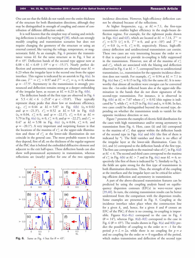
It is well known that the simplest way of tuning and switch-ing deflections is realized by varying θ [38], which can stronglymodify coupling and transmission scenarios but does notrequire changing the geometry of the structure or using anexternal control, like varying the voltage, temperature, or mag-netostatic field. As an example, Fig. 6 presents the transmit-tance versus kL for the same structure as in Fig. 4 but atθ � 45°. Deflection bands of the second type appear now at6.08 < kL < 6.49 (−19° < φ < −15.1°). Nearly perfect de-flection and asymmetric transmission are obtained near kL �6.23 when the irregular layer is the second one from the upperinterface. This regime is indicated by an asterisk in Fig. 6(a). Inthis case, T→ � t→−1 > 0.97 and T← � t←−1 � t0 � 0, whereasφ � −17.5°. Asymmetry in the transmission is strongly pro-nounced and deflection remains strong at a deeper embeddingof the irregular layer, as occurs at kL � 6.23 in Fig. 6(b).
The deflection bands of the first type are observed in Fig. 6at 5.5 < kL < 6 (−25.8° < φ < −19.8°). They typicallyrepresent sharp peaks that show low or moderate efficiency,e.g., t→−1 � 0.44 at kL � 5.87 in Fig. 6(b) (t0 ≈ 0.02and φ � −21.3°), t←−1 � 0.52 at kL � 5.8 in Fig. 6(d)(t0 ≈ 0.04, t→−1 ≈ 0, and φ � −22.1°), t←−1 � 0.4 at kL �5.79 in Fig. 6(e) (t0 ≈ 0, t→−1 ≈ 0, and φ � −22.2°), and t←−1 �0.47 at kL � 5.98 in Fig. 6(e) (t0 ≈ 0.04, t→−1 ≈ 0, andφ � −20.1°). A very important and surprising feature is thatthe locations of the maxima of t→−1 at the upper-side illumina-tion and those of t←−1 at the lower-side illumination do notcoincide in the general case. The most probable reason is thatthey depend, first of all, on the thickness of the regular segmentof the PhC that is behind the embedded diffractive element andadjacent to the exit half-space. These deflection bands can alsoshow well-pronounced asymmetry in transmission, whereasreflections are (nearly) perfect for one of the two opposite
incidence directions. However, high-efficiency deflection can-not be obtained because of the reflections.
At higher frequencies, e.g., at kL � 7.1, the first-typetransmission enables higher efficiency in the single-beam de-flection regime. For example, for the rightmost peaks shownin Figs. 6(e) and 6(f ), which are located at kL � 7.14, T← �t←−1 � 0.73 (t→−1 ≈ 0, T→ ≈ 0, and φ ≈ −10°) and T← �t←−1 � 0.8 (t0 � 0, t→−1 ≈ 0), respectively. Hence, high-effi-ciency deflection and unidirectional transmission can coexist.These two cases are very interesting because the order m �0 that is expected to provide in-coupling is fully suppressedin the transmission. However, not all of the maxima of t→−1and t←−1, which are associated with the blazing and deflectionobserved in Fig. 6 at kL > 7, correspond here to unidirectionaltransmission, i.e., transmission for the opposite incidence direc-tion does not vanish. For example, t←−1 � 0.94 at kL � 7.1 inFig. 6(e) but t→−1 ≈ 0.15 in Fig. 6(b) for the same kL. It is note-worthy that almost all incident wave energies can be convertedinto the −1st-order deflected beam also at the upper-side illu-mination in the bands that do not show signatures of thesecond-type transmission. For instance, it is observed inFig. 6(b) at kL � 7.07 where t→−1 > 0.92 (this regime is indi-cated by *), while t←−1 ≈ 0.25 in Fig. 6(e) and t0 ≈ 0.06. In fact,two cases could be distinguished beyond the second type, de-pending on whether the transmission tends to vanish for theopposite incidence direction or not.
Figure 7 presents the examples of electric field distribution forthe cases with high transmittance and/or strong asymmetry intransmission from Fig. 6. Here, cases (ii) and (iii) correspondto the maxima of t→−1 that appear within the deflection bandsof the second type in Figs. 6(a) and 6(b) (the first of them isindicated by *). The field vanishes and there is no effect ofthe irregular layer at the lower-side illumination. Cases (i),(iv), and (v) correspond to the deflection bands of the first type.The first case corresponds to the maximal value of t←−1 in Fig. 6(d)at kL < 6. The second and third cases correspond to the maximaof t→−1 in Fig. 6(b) at kL > 7 and in Fig. 6(c) near kL � 6, re-spectively (the first of them is indicated by *). Similarly to Fig. 5,the fields are quite strong for the first type of transmission inboth illumination directions. Thus, the strength of the couplingat the interfaces and the irregular layer can be critical for achiev-ing efficient deflection and asymmetry in transmission.
A part of the above-discussed transmission features can bepredicted by using the coupling analysis based on equifre-quency dispersion contours (EFCs) in wave-vector space[39,40]. In turn, the existing transmission results can be betterunderstood from the comparison with the dispersion results.Some examples are presented in Fig. 8. Coupling at theincidence interface takes place when the construction linefor a given kx and, hence, for a given k and θ crosses anEFC of the PhC; if there is no crossing, in-coupling is impos-sible. Figures 8(a)–8(c) correspond to the case in Fig. 4(θ � 14°), whereas Figs. 8(d)–8(f ) correspond to the case inFig. 6 (θ � 45°). The results shown in Figs. 8(a) and 8(b) pre-dict the possibility of coupling to the order m � −1 for theperiod p � L � 2a, while there is no coupling for p � aand no coupling for the order m � 0 regardless of the period,which makes transmission and deflection of the second type
6 6.5 70
0.5
1
T
6 6.5 70
0.5
1
6 6.5 70
0.5
1
T
6 6.5 70
0.5
1
6 6.5 70
0.5
1
kL
T
6 6.5 70
0.5
1
kL
(a)
(c)
(e)
(f)
*
**(b)
*
(d)
2
2
2
1
1
1
1
1
1
1
1
1
1
1
Fig. 6. Same as Fig. 4 but for θ � 45°.
2454 Vol. 33, No. 12 / December 2016 / Journal of the Optical Society of America A Research Article
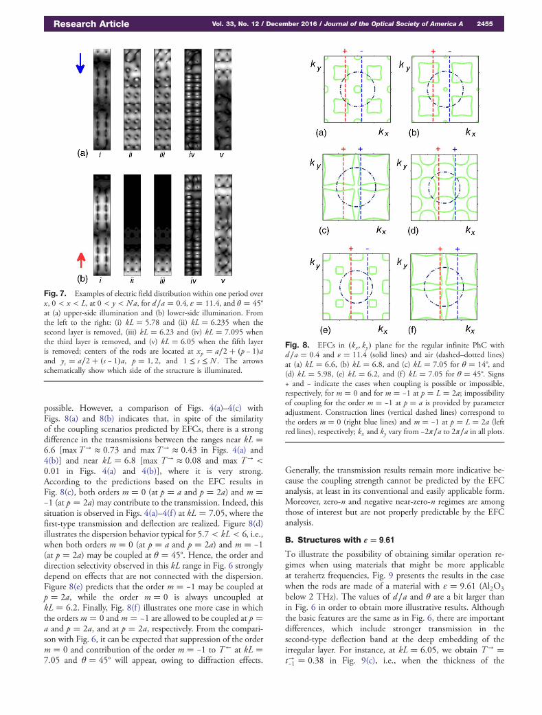
possible. However, a comparison of Figs. 4(a)–4(c) withFigs. 8(a) and 8(b) indicates that, in spite of the similarityof the coupling scenarios predicted by EFCs, there is a strongdifference in the transmissions between the ranges near kL �6.6 [maxT→ ≈ 0.73 and maxT→ ≈ 0.43 in Figs. 4(a) and4(b)] and near kL � 6.8 [max T→ ≈ 0.08 and max T→ <0.01 in Figs. 4(a) and 4(b)], where it is very strong.According to the predictions based on the EFC results inFig. 8(c), both orders m � 0 (at p � a and p � 2a) and m �−1 (at p � 2a) may contribute to the transmission. Indeed, thissituation is observed in Figs. 4(a)–4(f ) at kL � 7.05, where thefirst-type transmission and deflection are realized. Figure 8(d)illustrates the dispersion behavior typical for 5.7 < kL < 6, i.e.,when both orders m � 0 (at p � a and p � 2a) and m � −1(at p � 2a) may be coupled at θ � 45°. Hence, the order anddirection selectivity observed in this kL range in Fig. 6 stronglydepend on effects that are not connected with the dispersion.Figure 8(e) predicts that the order m � −1 may be coupled atp � 2a, while the order m � 0 is always uncoupled atkL � 6.2. Finally, Fig. 8(f ) illustrates one more case in whichthe ordersm � 0 andm � −1 are allowed to be coupled at p �a and p � 2a, and at p � 2a, respectively. From the compari-son with Fig. 6, it can be expected that suppression of the orderm � 0 and contribution of the order m � −1 to T← at kL �7.05 and θ � 45° will appear, owing to diffraction effects.
Generally, the transmission results remain more indicative be-cause the coupling strength cannot be predicted by the EFCanalysis, at least in its conventional and easily applicable form.Moreover, zero-n and negative near-zero-n regimes are amongthose of interest but are not properly predictable by the EFCanalysis.
B. Structures with ε � 9.61
To illustrate the possibility of obtaining similar operation re-gimes when using materials that might be more applicableat terahertz frequencies, Fig. 9 presents the results in the casewhen the rods are made of a material with ε � 9.61 (Al2O3
below 2 THz). The values of d∕a and θ are a bit larger thanin Fig. 6 in order to obtain more illustrative results. Althoughthe basic features are the same as in Fig. 6, there are importantdifferences, which include stronger transmission in thesecond-type deflection band at the deep embedding of theirregular layer. For instance, at kL � 6.05, we obtain T→ �t→−1 � 0.38 in Fig. 9(c), i.e., when the thickness of the
Fig. 7. Examples of electric field distribution within one period overx, 0 < x < L, at 0 < y < Na, for d∕a � 0.4, ε � 11.4, and θ � 45°at (a) upper-side illumination and (b) lower-side illumination. Fromthe left to the right: (i) kL � 5.78 and (ii) kL � 6.235 when thesecond layer is removed, (iii) kL � 6.23 and (iv) kL � 7.095 whenthe third layer is removed, and (v) kL � 6.05 when the fifth layeris removed; centers of the rods are located at xp � a∕2� �p − 1�aand ys � a∕2� �s − 1�a, p � 1; 2, and 1 ≤ s ≤ N . The arrowsschematically show which side of the structure is illuminated.
Fig. 8. EFCs in �kx ; ky� plane for the regular infinite PhC withd∕a � 0.4 and ε � 11.4 (solid lines) and air (dashed–dotted lines)at (a) kL � 6.6, (b) kL � 6.8, and (c) kL � 7.05 for θ � 14°, and(d) kL � 5.98, (e) kL � 6.2, and (f ) kL � 7.05 for θ � 45°. Signs+ and − indicate the cases when coupling is possible or impossible,respectively, for m � 0 and for m � −1 at p � L � 2a; impossibilityof coupling for the order m � −1 at p � a is provided by parameteradjustment. Construction lines (vertical dashed lines) correspond tothe orders m � 0 (right blue lines) and m � −1 at p � L � 2a (leftred lines), respectively; kx and ky vary from −2π∕a to 2π∕a in all plots.
Research Article Vol. 33, No. 12 / December 2016 / Journal of the Optical Society of America A 2455
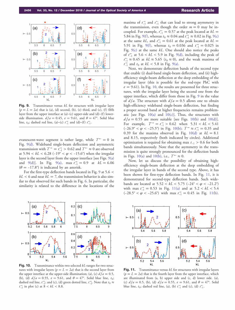
evanescent-wave segment is rather large, while T← � 0 inFig. 9(d). Wideband single-beam deflection and asymmetrictransmission with T→ � t→−1 > 0.62 and T← ≈ 0 are observedat 5.94 < kL < 6.28 (−19° < φ < −15.6°) when the irregularlayer is the second layer from the upper interface [see Figs. 9(a)and 9(d)]. In Fig. 9(a), max t→−1 � 0.9 at kL � 6.06(θ � −17.8°) is indicated by an asterisk.
For the first-type deflection bands located in Fig. 9 at 5.6 <kL < 6 and near kL � 7, the transmission behavior is also sim-ilar to that observed for such bands in Fig. 6. In particular, thesimilarity is related to the difference in the locations of the
maxima of t→−1 and t←−1 that can lead to strong asymmetry inthe transmission, even though the order m � 0 may be in-coupled. For example, t←−1 � 0.57 at the peak located at kL �5.84 in Fig. 9(f ), whereas t0 ≈ 0.04 and t→−1 ≈ 0.02 in Fig. 9(c)at the same kL, and t←−1 � 0.61 at the peak located at kL �5.91 in Fig. 9(f ), whereas t0 � 0.036 and t→−1 � 0.025 inFig. 9(c) at the same kL. One should also notice the peaksof t←−1 at 5.6 < kL < 5.9 in Fig. 9(d), including the peak oft←−1 ≈ 0.45 at kL ≈ 5.65 (t0 ≈ 0), and the weak maxima oft→−1 and t0 at kL < 5.8 in Fig. 9(a).
Next, we demonstrate deflection bands of the second typethat enable (i) dual-band single-beam deflection, and (ii) high-efficiency single-beam deflection at the deep embedding of theirregular layer (this is possible for the rod-type PhC withε � 9.61). In Fig. 10, the results are presented for three struc-tures, with the irregular layer being the second one from theupper interface, which differ from those in Fig. 9 in the valueof d∕a. The structure with d∕a � 0.5 allows one to obtainhigh-efficiency wideband single-beam deflection, but findinga proper second band at higher frequencies remains problem-atic [see Figs. 10(a) and 10(c)]. Thus, the structures withd∕a � 0.55 are more suitable [see Figs. 10(b) and 10(d)].For example, T→ � t→−1 > 0.62 when 5.31 < kL < 5.41(−26.9° < φ < −25.5°) in Fig. 10(b); T→ ≈ t→−1 � 0.35 and0.39 for the maxima observed in Fig. 10(d) at kL � 8.1and 8.15, respectively (both indicated by circles). Additionaloptimization is required for obtaining max t−1 > 0.6 for bothbands simultaneously. Note that the asymmetry in the trans-mission is quite strongly pronounced for the deflection bandsin Figs. 10(a) and 10(b), i.e., T← ≈ 0.
Now, let us discuss the possibility of obtaining high-efficiency single-beam deflection at the deep embedding ofthe irregular layer in bands of the second type. Above, it hasbeen shown for first-type deflection bands. In Fig. 11, it isdemonstrated for second-type deflection bands. Such wide-bands are located at 5.52 < kL < 5.75 (−24° < φ < −21.2°)with max t→−1 � 0.53 in Fig. 11(a) and at 5.2 < kL < 5.4(−28.5° < φ < −25.6°) with max t→−1 � 0.45 in Fig. 11(b).
5.5 6 6.5 70
0.5
1T
5.5 6 6.5 70
0.5
1
5.5 6 6.5 70
0.5
1
T
5.5 6 6.5 70
0.5
1
5.5 6 6.5 70
0.5
1
kL
T
5.5 6 6.5 70
0.5
1
kL
1
1
1
12
1 1
1
1
*
(c)
(d)
(e)
(f)
(b)
2
2
(a)
Fig. 9. Transmittance versus kL for structure with irregular layer(p � L � 2a) that is (a), (d) second, (b), (e) third, and (c), (f ) fifthlayer from the upper interface at (a)–(c) upper-side and (d)–(f ) lower-side illumination. d∕a � 0.45, ε � 9.61, and θ � 47°. Solid blueline, t0; dashed red line, (a)–(c) t→−1 and (d)–(f ) t←−1.
Fig. 10. Transmittance within two selected kL-ranges for two struc-tures with irregular layers (p � L � 2a) that is the second layer fromthe upper interface at the upper-side illumination; (a), (c) d∕a � 0.5,(b), (d) d∕a � 0.55, ε � 9.61, and θ � 47°. Solid blue line, t0;dashed red line, t→−1; and (c), (d) green dotted line, t→−2. Note that t0 ≈t→−2 in plot (c) at 8 < kL < 8.8.
Fig. 11. Transmittance versus kL for structures with irregular layers(p � L � 2a) that is the fourth layer from the upper interface, whichare illuminated from (a, b) upper side and (c, d) lower side. (a),(c) d∕a � 0.5, (b), (d) d∕a � 0.55, ε � 9.61, and θ � 47°. Solidblue line, t0; dashed red line, (a), (b) t→−1 and (c), (d) t←−1.
2456 Vol. 33, No. 12 / December 2016 / Journal of the Optical Society of America A Research Article
A similar band can be obtained for d∕a � 0.6 at 4.95 < kL <5.1 (−32.5° < φ < −30°) with max t→−1 � 0.58. Hence, wide-band deflection and unidirectional transmission can be ob-tained for the second-type bands also at the deepembedding. In this case, weak damping in the regular partof the PhC, which is located between the incidence interfaceand the irregular layer, is critical. It is noteworthy that the ad-vancements presented in Figs. 10 and 11 have not yet beenfound in the structures with ε � 11.4 but are expected to existat different values of d∕a.
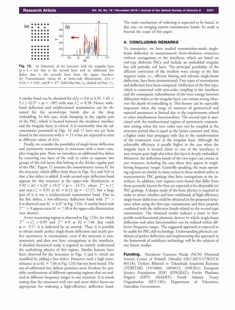
Finally, we consider the possibility of single-beam deflectionand asymmetric transmission in structures with a more com-plex irregular part. Now, we introduce an additional line defectby removing one layer of the rods in order to separate twogroups of the rod layers that belong to the thicker regular partof the PhC. Figure 12 presents the transmittance versus kL forthe structure, which differs from those in Figs. 9(a) and 9(d) inthat a line defect is added. A wide second-type deflection bandappears for this structure at the upper-side illumination at5.92 < kL < 6.29 (−19.3° < φ < −15.5°), where T→ ≈ t→−1and max t→−1 � 0.91 at kL � 6.12 (φ � −17.2°), but a largepart of it is not a unidirectional transmission band. Due tothe line defect, a low-efficiency deflection band with T← >0 is observed near kL � 6.07 in Fig. 12(b). A similar band withT→ > 0 appears near kL � 7.38 at the upper-side illumination(not shown).
A very interesting regime is observed in Fig. 12(b), for whichT← � t←−1 > 0.99 and T→ ≈ 0 at kL � 7.06 that yieldsφ � −9.1°; it is indicated by an asterisk. Thus, it is possibleto obtain nearly perfect single-beam deflection and nearly per-fect asymmetry in transmission, even if the structure is non-symmetric and does not have corrugations at the interfaces.A detailed theoretical study is required to entirely understandthe underlying physics of this regime. Similar features havebeen observed for the structures in Figs. 4 and 6, which aremodified by adding a line defect. However, such a high trans-mittance as at kL � 7.06 in Fig. 12(b) has not been found. Theuse of additional line defects promises more freedom for pos-sible combinations of different operating regimes that are real-ized in different frequency ranges in one structure. It is worthnoting that the structures with two and more defect layers areappropriate for widening a high-efficiency deflection band.
The main mechanism of widening is expected to be based, inthis case, on merging narrow transmission bands. Its study isbeyond the scope of this paper.
4. CONCLUDING REMARKS
To summarize, we have studied transmission-mode single-beam deflection in nonsymmetric finite-thickness structureswithout corrugations at the interfaces, which are based onrod-type dielectric PhCs and include an embedded irregularbut still periodic rod layer. The principal possibility of theefficient conversion of the incident wave energy to the firstnegative order, i.e., efficient blazing and relevant single-beamdeflection, have been demonstrated. Two types of transmissionand deflection have been compared. Deflection of the first type,which is connected with zero-order coupling at the interfacesand the consequent redistribution of the wave energy betweendiffraction orders at the irregular layer, can remain strong what-ever the depth of embedding is. This feature can be especiallyimportant when the range of variation of geometrical andmaterial parameters is limited due to the requirements relatedto other simultaneous functionalities. The second type is asso-ciated with the unidirectional regime of asymmetric transmis-sion arising when the zero order may not be coupled at thestructure period that is equal to the lattice constant and, thus,a higher order may propagate only due to the transformationof the evanescent wave at the irregular layer. Although theachievable efficiency is usually higher in the case when theirregular layer is located closer to one of the interfaces, itmay remain quite high also when this layer is deeply embedded.Moreover, the deflection bands of the two types can coexist inone structure, including the case when they appear in neigh-boring frequency ranges. Generally speaking, the main operat-ing regimes are similar in many senses to those studied earlier innonsymmetric PhC gratings that have corrugations at the in-terfaces. In addition, new regimes were found that differ fromthose presently known for (but are expected to be obtainable in)PhC gratings. A deeper study of the basic physics is required inorder to detect whether and how widebands of high-efficiencysingle-beam deflection could be obtained in the proposed struc-tures when using the first-type transmission and then properlycombined with the deflection bands related to the second-typetransmission. The obtained results indicate a route to low-profile multifunctional photonic devices in which single-beamdeflection and other functionalities can be realized within dif-ferent frequency ranges. The suggested approach is expected tobe usable for PhC slab technology. Understanding physical con-ditions of perfect deflection and implementing this approach inthe framework of multilayer technology will be the subjects ofour future studies.
Funding. Narodowe Centrum Nauki (NCN) (NationalScience Center of Poland) (MetaSel DEC-2015/17/B/ST3/00118); Türkiye Bilimsel ve Teknolojik Araştirma Kurumu(TÜBİTAK) (107A004, 109A015, 109E301); EuropeanScience Foundation (ESF) (EPIGRAT); Devlet PlanlamaÖrgütü (DPT) (HAMIT); North Atlantic TreatyOrganization (SET-181); Department of Education,Australian Government.
Fig. 12. (a) Schematic of the structure with the irregular layer(p � L � 2a) that is the second layer and an additional linedefect that is the seventh layer from the upper interface.(b) Transmittance versus kL at lower-side illumination. d∕a �0.45, ε � 9.61, and θ � 47°. Solid blue line, t0; dashed red line, t←−1.
Research Article Vol. 33, No. 12 / December 2016 / Journal of the Optical Society of America A 2457
Acknowledgment. The contribution of A. E. S. was par-tially supported by the Australian Government under theEndeavour Fellowship Programme. E. O. acknowledges partialsupport from the Turkish Academy of Sciences.
REFERENCES
1. D. Maystre, “Photonic crystal diffraction gratings,” Opt. Express 8,209–216 (2001).
2. A. E. Serebryannikov and E. Ozbay, “One-way Rayleigh–Woodanomalies and tunable narrowband transmission in photonic crystalgratings with broken structural symmetry,” Phys. Rev. A 87,053804 (2013).
3. A. Mandatori, M. Bertolotti, and C. Sibilia, “Asymmetric transmission ofsome two-dimensional photonic crystals,” J. Opt. Soc. Am. B 24, 685–690 (2007).
4. A. E. Serebryannikov, A. O. Cakmak, and E. Ozbay, “Multichanneloptical diode with unidirectional diffraction relevant total transmission,”Opt. Express 20, 14980–14990 (2012).
5. L. Zinkiewicz, J. Haberko, and P. Wasylczyk, “Highly asymmetric nearinfrared light transmission in an all-dielectric grating-on-mirror pho-tonic structure,” Opt. Express 23, 4206–4211 (2015).
6. S. Collardey, A.-C. Tarot, P. Pouliguen, and K. Mahdjoubi, “Use ofelectromagnetic band-gap materials for RCS reduction,” MicrowaveOpt. Technol. Lett. 44, 546–550 (2005).
7. A. E. Serebryannikov, T. Magath, and K. Schuenemann, “Braggtransmittance of s-polarized waves through finite-thickness photoniccrystals with periodically corrugated interface,” Phys. Rev. E 74,066607 (2006).
8. R. Petit, Electromagnetic Theory of Gratings (Springer, 1980).9. A. Figotin and I. Vitebskiy, “Electromagnetic unidirectionality in
magnetic photonic crystals,” Phys. Rev. B 67, 165210 (2003).10. F. D. M. Haldane and S. Raghu, “Possible realization of directional
optical waveguides in photonic crystals with broken time-reversalsymmetry,” Phys. Rev. Lett. 100, 013904 (2008).
11. A. E. Serebryannikov and E. Ozbay, “Unidirectional transmission innon-symmetric gratings containing metallic layers,” Opt. Express17, 13335–13345 (2009).
12. A. E. Serebryannikov, E. Ozbay, and S. Nojima, “Asymmetric trans-mission of terahertz waves using polar dielectrics,” Opt. Express 22,3075–3088 (2014).
13. Y. Fu, L. Xu, Z. H. Hang, and H. Chen, “Unidirectional transmissionusing array of zero-refractive-index metamaterials,” Appl. Phys. Lett.104, 193509 (2014).
14. P. Rodriguez-Ulibarri, M. Beruete, M. Navarro-Cia, and A. E.Serebryannikov, “Wideband unidirectional transmission with tunablesign-switchable refraction and deflection in nonsymmetric structures,”Phys. Rev. B 88, 165137 (2013).
15. M. J. Lockyear, A. P. Hibbins, K. R. White, and J. R. Sambles, “One-way diffraction grating,” Phys. Rev. E 74, 056611 (2006).
16. C. Wang, C.-Z. Zhou, and Z.-Y. Li, “On-chip optical diode based onsilicon photonic crystal heterojunctions,” Opt. Express 19, 26948–26955 (2011).
17. J. H. Oh, H. W. Kim, P. S. Ma, H. M. Seung, and Y. Y. Kim, “Invertedbi-prism phononic crystals for one-sided elastic wave transmissionapplications,” Appl. Phys. Lett. 100, 213503 (2012).
18. J. H. Shi, H. F. Ma, C. Y. Guan, Z. P. Wang, and T. J. Cui, “Broadbandchirality and asymmetric transmission in ultrathin 90°-twisted Babinet-inverted metasurfaces,” Phys. Rev. B 89, 165128 (2014).
19. C. Pfeiffer, C. Zhang, V. Ray, L. J. Guo, and A. Grbic, “High perfor-mance bianisotropic metasurfaces: asymmetric transmission of light,”Phys. Rev. Lett. 113, 023902 (2014).
20. S. Cakmakyapan, A. E. Serebryannikov, H. Caglayan, and E. Ozbay,“Spoof-plasmon relevant one-way collimation and multiplexing atbeaming from a slit in metallic grating,” Opt. Express 20, 26636–26648 (2012).
21. E. Battal, T. A. Yogurt, and A. K. Okyay, “Ultrahigh contrast one-wayoptical transmission through a subwavelength slit,” Plasmonics 8,509–513 (2013).
22. F. V. Liu, D. A. B. Miller, and S. Fan, “Ultra-compact photonic crystalwaveguide spatial mode converter and its connection to the opticaldiode effect,” Opt. Express 20, 28388–28397 (2012).
23. H. Ye, D. Wang, Z. Yu, J. Zhang, and Z. Chen, “Ultra-compact broad-band mode converter and optical diode based on linear rod-type pho-tonic crystal waveguide,” Opt. Express 23, 9673–9680 (2015).
24. H. Kurt, D. Yilmaz, A. E. Akosman, and E. Ozbay, “Asymmetric lightpropagation in chirped photonic crystal waveguides,” Opt. Express20, 20635–20646 (2012).
25. L. Feng, M. Ayache, J. Huang, Y.-L. Xu, M.-H. Lu, Y. F. Chen, Y.Fainman, and A. Scherer, “Nonreciprocal light propagation in a siliconphotonic circuit,” Science 333, 729–733 (2011).
26. Y.-L. Xu, L. Feng, M.-H. Lu, and Y.-F. Chen, “Asymmetric opticalmode conversion and transmission by breaking PT-symmetry on sil-icon photonic circuits,” Phys. Lett. A 376, 886–890 (2012).
27. M. C. Hutley, Diffraction Gratings (Academic, 1982).28. P. Lalanne, S. Astilean, P. Chavel, E. Cambril, and H. Launois,
“Design and fabrication of blazed binary diffractive elements with sam-pling periods smaller than the structural cutoff,” J. Opt. Soc. Am A 16,1143–1156 (1999).
29. P. Lalanne, “Waveguiding in blazed-binary diffractive elements,” J.Opt. Soc. Am A 16, 2517–2520 (1999).
30. C. Ribot, M.-S. L. Lee, S. Collin, S. Bansropun, P. Plouhinec, D.Thenot, S. Cassette, B. Loiseaux, and P. Lalanne, “Broadband andefficient diffraction,” Adv. Opt. Mater. 1, 489–493 (2013).
31. C. Pfeiffer and A. Grbic, “Metamaterial Huygens’ surfaces: tailoringwave fronts with reflectionless sheets,” Phys. Rev. Lett. 110,197401 (2013).
32. A. Epstein and G. Eleftheriades, “Huygens’ metasurfaces via theequivalence principle: design and applications,” J. Opt. Soc. Am. B33, A31–A50 (2016).
33. E. Colak, A. E. Serebryannikov, P. V. Usik, and E. Ozbay, “Diffractioninspired unidirectional and bidirectional beam splitting in defect-containing photonic structures without interface corrugations,” J.Appl. Phys. 119, 193108 (2016).
34. K. Inoue and K. Othaka, eds., Photonic Crystals: Physics, Fabricationand Applications (Springer, 2004).
35. T. Magath and A. E. Serebryannikov, “Fast iterative, coupled-integral-equation technique for inhomogeneous profiled and periodicslabs,” J. Opt. Soc. Am. A 22, 2405–2418 (2005).
36. See www.cst.com for software details.37. W.-M. Ye, X.-D. Yuan, C.-C. Guo, and C. Zen, “Unidirectional trans-
mission in non-symmetric gratings made of isotropic material,” Opt.Express 18, 7590–7595 (2010).
38. J. H. Wu, L. K. Ang, A. Q. Liu, H. G. Teo, and C. Lu, “Tunable high-Qphotonic-bandgap Fabry–Perot resonator,” J. Opt. Soc. Am. B 22,1770–1777 (2005).
39. A. E. Serebryannikov, E. Colak, A. Petrov, P. V. Usik, and E. Ozbay,“Multifrequency spatial filtering: a general property of two-dimensionalphotonic crystals,” Photon. Nanostr. Fundam. Appl. 18, 1–9(2016).
40. S. Foteinopoulou and C. M. Soukoulis, “Electromagnetic wavepropagation in two-dimensional photonic crystals: a study of anoma-lous refractive effects,” Phys. Rev. B 72, 165112 (2005).
2458 Vol. 33, No. 12 / December 2016 / Journal of the Optical Society of America A Research Article