Embed Size (px)
Citation preview
VOL.12 No. 6, pp. 157-184 DEGEMBER 1950
Philips Technical ReviewDEAIJNG ~TH TEC~CAL PROBLE~
RELATING TO THE PRODUCTS, PROCESSES AND INVESTIGATIONS OFTHE PHILIPS INDUSTRIES
EDITED BY THE RESEARCH LABORATORY OF N.V. PHILIPS' GLOEILAMPENFABRIEKEN, EINDHOVEN, NETHERLAND
TWO TRANSMITTING VALVES FOR USE IN MOBILE INSTALLATIONS
by E. G. DORGELO and P. ZIJLSTRA. 621.385.4:621.396.61 :62I.396.72
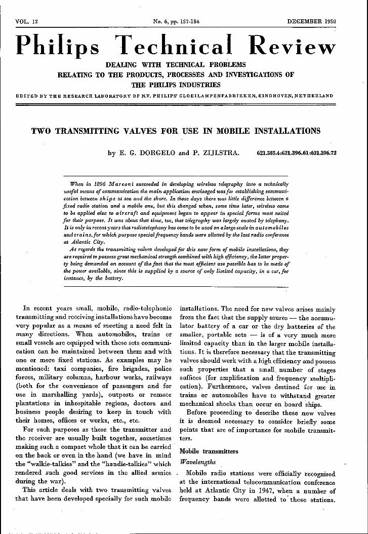
When in 1896 Marconi succeeded in developing wireless telegraphy into a technicallyuseful means of communication the main application envisaged was [or estobliehing communi-cation between ships at sea and the shore. In those days there was little difference between afixed radio station and a mobile one, but this changed when, some time later, toireless cameto be applied also to a ircraft and equipment began to appear in special forms most suitedfor their purpose. It was about that time, too, that telegraphy was largely ousted by telephony.It is only in recent years that radiotelephony has come to be used on a largescale in a uta mob ilesand tr ai n s.for which purpose specialfrequency bands were allotted by the last radio conferenceat Atlantic City.
As regards the transmitting valves developed for this new form of mobile installations, theyare required to possess great mechanical strength combined with ltigh efficiency, the lauer proper-ty being demanded on account of the fact that the most efficient use possible has to be made ofthe power available, since this is supplied by a source of only limited capacity, in a car, forinstance, by the battery.
In recent years small, mobile, radio-telephonictransmitting and receiving installations have becomevery popular as a means of meeting a need felt inmany directions. When automobiles, trains orsmall vessels are equipped with these sets communi-cation can be maintained between them and withone or more fixed stations. As examples may bementioned: taxi companies, fire brigades, policeforces, military columns, harbour works, railways(both for the convenience of passengers and foruse in marshalling yards), outposts or remoteplantations in inhospitable regions, doctors andbusiness people desiring to keep in touch withtheir homes, offices or works, etc., etc.
For such purposes as these the transmitter andthe receiver are usually built together, sometimesmaking such a compact whole that it can be carriedon the back or even in the hand (we have in mindthe "walkie-talkies" and the "handle-talkies" whichrendered such good services in the allied armiesduring the war).
This article deals with two transmIttmg valvesthat have been developed specially for such mobile
installations. The need for new valves arises mainlyfrom the fact that the supply source - the accumu-lator battery of a car or the dry batteries of thesmaller, portable sets - is of a very much morelimited capacity than in the larger mobile installa-tions. It is therefore necessary that the transmittingvalves should work with a high efficiency and possesssuch properties that a small. number of stagessuffices (for amplification and frequency multipli-cation). Furthermore, valves destined fur use intrains or automobiles have to withstand greatermechanical shocks than occur on board ships.Before proceeding to' describe these new valves
it is deemed necessary to consider briefly somepoints that are of importance for mobile transmit-ters.
Mobile transmitters
Wavelengths
Mobile radio stations were officially recognisedat the international telecommunication conferenceheld at Atlantic City in 1947, when a number offrequency bands were allotted to' these stations.

158 PHILIPS TECHNICAL REVIEW VOL. 12, No. 6
For such of these bands as lie between 54 and 420Mc/s (5.55 to 0.714 m waves) their distributionis indicated in fig. 1.
The other bands outside these limits have notbeen inc1uded in this diagram for the followingreasons. At frequencies below a certain limit thereis a risk of the waves being reflected by the iono-sphere and reaching the earth again in parts farremoved from the transmitter 1); welcome use ismade of this for long-distance radio communication,but for transmitters intended only for short-rangework, like mobile transmitters, this reflection bythe ionosphere is undesirable because it is apt tolead to interference over wide ranges where thesame wavelengths are being used. At frequenciesof 54 Mc/s and higher there is no need to takeaccount of this effect, although at the highest allot-
There are some exceptions however: the 85-87.5 Mc/s banddoes not apply for Great Britain, which has instead the dis-posal of the 66.5-68 Mcfs band; South Africa and .its mandatoryterritories have been allotted, instead of the 100-108 Mc/s band,the bands 133-144 and 146-174 Mc/s and also, but only formobile stations used for broadcasting, the 54-68 Mc/s band.
Zone Il, comprising mainly North and South America, hasbeen allotted the 54-88, 132-144, 148-220, 225-328.6 and 335.4-420 Mc/s bands.
Zone TlI, consisting mainly of that part ofAsia not includedin zone I and of Australia and New Zealand, has the disposalofthe bands 54-68, 70-78, 80·87 (in Australia and New Zealand80-85),132-144 (not in Australia and New Zealand), 148-200(in Australia limited to 156-170 and 178-200, in New Zealandlimited to 156-200), 235-328.6 and 335.4-420 Mc/s.
In order to avoid interference with or from otherradio communications, mobile transmitters arenot allowed to work outside the fixed frequency
Zone I_" r---nODOr: n f--lf~-I I I 1 1,- lIfels,II
, ,50 iD 150 200 _f 250 300 :ia 400 I
Zone!1~ 1 nl, I I1250
, I 1 J50 400 411-50 1()() 150 200 300
Zon,UI nn01 fl rur.n I , 3bo I 1 :ia 400 Ja,_.5ö 100 150 200 250
67949
Fig. 1. The frequency bands allotted to mobile transmitters by the International Tele-communications Conference held at Atlantic City in 1947, for so far as these bands liebetween 54 and 420 Mc/s. Roughly speaking zone I comprises Europe, Africa and part ofAsia, zone Il North and South America, and zone III the part of Asia not belongingto zone I, and AUl!tralia and NewZealand. The bands denoted by dotted lines can onlybe used in certain parts of the respective zone. For further details see the text in small type.
, ted frequencies under certain atmospheric condi-tions an inversion of the temperature gradientoccurs and the signals may cover a range of somehundreds of kilometres, but then the ionospherehas nothing to do with this; such conditions, how-ever, very seldom occur.The other limit, 420 Mc/s, is about the highest
frequency at which the transmitting valves to bedescribed here still work with a satisfactory efficien-cy; for still higher frequencies entirely differenttypes of valves would be required.
For the allocation of frequencies for working mobile trans-'mitters the world has been divided into three zones, wherethe following arrangements apply for the frequencies between54 and 420 Mc/s.In zone I, covering Europe, Africa and some parts of Asia,
the frequency bands that may be used are: 70-72.8, 75.2-78,80-83, 85-87.5,100-108, 156-174, 235-328.6 and 335.4-420 Mc/s.
1) See, e.g.: C. J. Bakker, Radio investigation of the iono-sphere, Philips Techn. Rev. 8, 111-120, 1946.
bands, and in order to avoid any mutual inter-ference their frequency has to be highly constant.For this reason crystal control has to be applied.
Power and range'The power of mobile transmitters is closely related
on the one hand to the minimum range requiredand on the other hand to the permissible weightand volume of the apparatus, including the powersupply unit.The range depends not only upon the power
radiated by the aerial but also to a large extentupon the construction and height of the aerial,whilst also the surroundings are of great influence.The aerial constructions most favourable for radia-tion are generally too cumbersome to be of use onan automobile or train. The higher the aerial thegreater is the range, but then of course the heightis limited for travelling vehicles; on an automobile,for instance, as a rule a simple vertical rod onthe roof is used. In open spaces the range is much

DECEMBE;R 1950 TRANSl\:lITTING VALVES FOR MOBILE INSTALLATIONS 159
greater. than in built-up areas; the adverse influenceof buildings is, roughly speaking, felt most at thehighest frequencies, though there are exceptionsto this rule. In New York, for instance, it hasbeen found that in narrow streets shorter wavesare more readily reflected downward by buildingsthan 'are longer ones. A second reason for shorterwaves being sometimes more satisfactory in a townis that in ~ street standing waves are apt to heset up; when driving through such a street onetherefore passes through maxima and minima,and the quicker these follow each other - thesmaller the wavelength - the less does intelli-gibility suffer.
Intermittent working
If a call is to he heard at once, the receiver ina mobile radio station must be continuously inthe stand-by position. Mter a call has been received,or when another station has to be called up, theinstallation is changed ov~r to transmission, mostlyby means of a switch built into the microphonehandle. This changing over is then repeated asthe conversatien proceeds to and fro. Since as arule the intervals of rest between talks are muchlonger than the talks themselves, in practice thetransmitter is working only a fraction of the time,while the receiver is working almost continuously.Thanks to these long intervals, for some trans-mitting valves operating conditions are allowedwhich permit of a somewhat larger output thanwould be permissible for continuous working.
Number of stages of the transmitter
Notwithstanding the relatively short workingtime of the transmitter, it is necessary to aim atthe least possible power consumption, i.e. at ahigh total efficiency of the transmitter. We shallpresently deal further with the steps that have beentaken in the new transmitting valves in order tolimit the losses as far as possible, but anotherequally important factor upon which the totalefficiency depends is the number of stages requiredbetween the aerial and the quartz crystal determ-ining the carrier frequency.
This number of stages is closely related to thesystem of modulation. Two systems, amplitudemodulation and frequency modulation, are to heconsidered, both of which are applied in mobiletransmitters; it is not the place here to explainwhy in one case amplitude modulation is employedand frequency modulation in another.Where amplitude modulation is employed
one has a constant carrier frequency, which ofcourse has to lie in one of the frequency bandsallotted. Now the frequencies of these bands areso high that they cannot he generated directlyby means of a crystal. Owing to the .fragility ofthe crystal, especially when it is exposed to theshocks occurring in a mobile transmitter, about0.15 mm is the least thickness it may have, andthis eorresponds to a natural frequency of about20 Mc/s 2). For a carrier frequency of say 320 Mc/sit is therefore necessary to apply at least a Ifi-foldfrequency multiplication. In such cases it is advan-tageous to use do uble valves with the two electrodesystems, mounted in one envelope, connectedin cascade. By frequency doubling in each systemno more than two of these double valves are thenrequired to multiply the input (crystal) frequency16 times.In addition an output valve and a modulator
valve are needed and one or two stages of A.F.amplification between the microphone and themodulator.With frequency modulation a system can
he followed, for instance, as described by Braak 3),where the microphone voltage brings about aphase shift between two currents having the fre-quency of the quartz crystal, in such a way thatthe phase ep of the sum of these currents variesaccording to the equation
cp = wot + a sin 2n'Vt
where Wo = angular frequency of the crystal,t = time, a = amplitude of the phase shift (phasesweep), 'V = frequency of the incident sound atthe microphone. Corresponding to the phase modu-lation of the total current is a frequency modu-lation, the instantaneous value W of the varyingangular frequency being defined by
depW = de = Wo+ a' 2n'V cos 2n'Vt,
so that the instantaneous value f = w/2n of themodulated frequency is:
f= fo + a 'V cos 2n'Vt
(fo = wo/2n). The sweep of this frequency is av,For undistorted reproduetion the frequency sweep
9) Crystals are also being used, especially in the U.S.A. andin Great Britain, which oscillate with (practically) amultiple of the natural frequency (see, e.g., the articleby W. Parrish inthis number, p. 166), so thatfrequencieshigher than 20 Mcfs can be generated with still crystals.
8) D. J. Braak, Mobile radio equipment, type SRR 192,Communication News 10, 120-125, 1949 (No. 4).

160 PHILIPS TECHNICAL REVIEW VOL. 12, No. 6
has to be proportional to the intensity of the soundand independent of the audio frequency v,, whichmeans to say that the phase sweep a has to beproportional to the sound intensity and inversely'proportional to V 4). 'If an n-fold frequency multiplication is applied
between the modulating stage and the output stagethe sweep of the aerial frequency will thereforeamount to navo For transmitters which are modu-lated only with spe ech - as is the case with mobiletransmitters - this sweep has been limited byinternational agreement to 15,000 cis, and, in orderto derive the utmost benefit from frequency modu-lation this sweep has to be used to the full. Toprevent prohibitive non-linear distortion the phasesweep a has to be limited to an angle of about0.5 radian. Hence the frequency multiplicationrequired to get an aerial frequency sweep of 15,000cis with the maximum phase sweep, i.e. at thelowest audio frequency V occurring in telephony(300 cis), and with full phase modulation (a R:i 0.5radian), is
15,000n R:i ----- = 100 .
0.5 X 300
(Since this value of n is greater than that found inthe case of amplitude modulation, with frequencymodulation the mechanical strength of the crystalis not a determining factor.)A frequency multiplication of about 100 can be
obtained with three double valves, for instance asfollows: (3 X 2) X (2 X 2) X (2 X 2) = 96. For thefirst of these valves a low-power type suffices,which need not be made for particularly highfrequencies, e.g. the double triode ECC 40, butfor the third valve (and possibly also for the secondone), in which the frequency is much higher thanthe crystal frequency, it is preferable to use oneof the double tetrodes of the type QQC 04/15 orQQE 06/40 5) to be described in this article. Thesame types of valves can also be used as outputvalves (with either frequency or amplitude modula-tion), though then the two systems have to be con-nected in push-pull instead of in cascade; we shallrevert to this later.
4) The latter can be reached to a sufficient approximationby means of a correcting network between the microphoneand the phase modulator.
6) Here the letter Q means tetrode, QQ doubl? t;trode,C "directly-heàted 'oxide-coated cathode, E mdlr?ct!y-heated oxide-coated cathode. The figures 04 and 06 SIgnifythat the valve is intended for a supply voltage of 0.4 or
, 0.6 kV respectively, while the numbers 15 and 40 denotethe order of the output in watts (as will presently be seen,in suitably chosen circuits these valves can yield muchhigher outputs than 15 or 40 W).
Choice of the type. of valve
A tetrode, rather than a triode or a pentode,has been chosen because of a number of considera-tions, most of which apply in general to all trans-mitting valves for the frequency range in question,without being limited to valves for mobile trans-mitters. These considerations are the following.
At high frequencies a triode is in two respectsat a disadvantage compared with a screen-gridvalve (tetrode or pentode]; in the first place atriode requires a greater driving power 6) and thusalso necessitates a larger number of amplifyingstages, whilst in the second place with screen-gridvalves, compared with triodes, it is possible towork with fairly high frequencies without (external)neutralization, i.e. compensation of undesiredfeedback such as arises, for instance, owing to thecapacitance between anode and control grid.
That is why a screen-grid valve has been chosen.Of the two kinds to be considered, the tetrode andthe pentode, the former is to be preferred at veryhigh frequencies, since the absence of the thirdgrid permits of a smaller anode capacitance, î.e.the capacitance between the anode and the otherelectrodes together. The absence of the third grid,however, makes it necessary to take certain stepsfor preventing any secondary electrons emittedby the anode reaching the screen grid; the purposeof the third grid (suppressor grid) in a pentode isto bring about between the anode and the screengrid a potential minimum suppressing the undesiredsecondary emission. Such a pofential minimum,however, can be obtained by other means too, bygiving a tetrode system such dimensions that, withthe normal working currents and voltages, betweenthe anode and the screen grid a concentration ofspace charge is brought about which provides thedesired potential minimum 7).
Furthermore, the secondary emission itself canbe counteracted by coating the anode with a layerof a material from which the electrons do not easilyemerge' (see the article quoted in footnote 7)).Both these measures have been applied in the newtypes of transmitting valves.
The anode capacitance, already small owing tothe absence of a third grid, can be still furtherred~ced by dividing the electrode system into two
G) See J: P. Heyboer, Five-electrode transmit~g val,:es(pentodes), Philips Techn. Rev. 2, 257-265, 1937, ill partic-ular pp 260 and 261.
7) See, e.g.: J. L. H. Jonker, Secondary emission in outputvalves, Philips Techn. Rev. 10, 346-351, 1948, fig. 3,curve 1. The difficulty therein mentioned, which makesthis method unsuitable for output valves of low-frequencyamplifiers, applies in a much less degree for transmittingvalves.
DECEMBER 1950 TRANSMITTING VALVES FOR MOBILE INSTALLATIONS 161
parts and connecting the two halves to the externalcircuits in push-pull. With given total dimensionsof the electrodes (thus with a certain permissibleheat dissipation iii the valve) and certain distancesbetween the electrodes, the input and outputcapacitances are then four times smaller, since. thepartial capacitances are in series instead of inparallel.
When the two electrode systems of the doublevalve obtained by this division are connected incascade instead of. in push-pull the same type ofvalve can advantageously be used also for frequencymultiplying, as we have seen above.Transmitting valves with two electrode systems
in one envelope have in fact been known somefifteen years already. In the old designs the elec-trodes not carrying any high-frequency voltage(the cathodes and the screen grids) were connectedin pairs by short wires or strips, and the centres(neutral points) of the interconnections were led
A'
III . 16l! 62
--u --u-
"..---. ,....--.
K' K"
'l
, "---''----'
6; 61'~
n
IHI lAl
62951
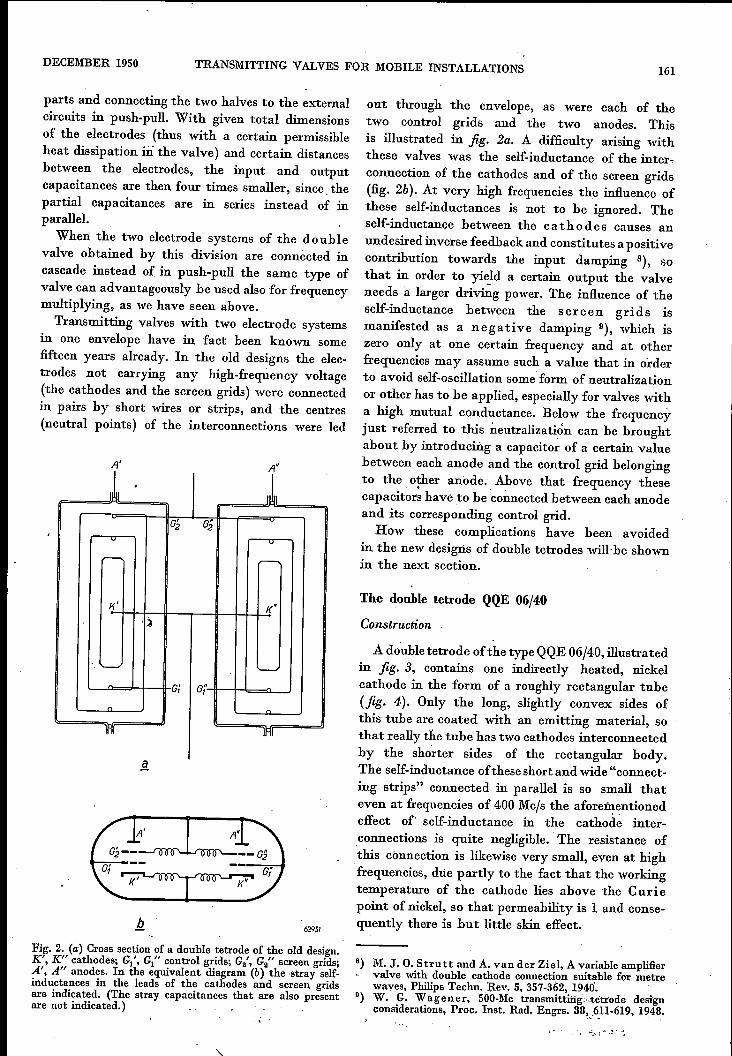
Fig. 2. (a) Cross section of a double tetrode of the old design.K', K" cathodes; G/, Gl" control grids; G2', G2" screen grids;A', A" anodes. In the equivalent diagram (b) the -stray self-inductances in the leads of the cathodes and screen gridsare indicated. (The stray capacitances that are also presentare not indicated.)
out through the envelope, as were each of thetwo control grids and the two anodes. Thisis illustrated in fig. 2a. A difficulty arising withthese valves was the self-inductance of the inter.connection of the cathodes and of the screen grids(fig. 2b). At very high frequencies the influence ofthese self-inductances is not to be ignored. Theself-inductance between the cathodes causes anundesired inverse feedback and constitutes a positivecontribution towards the input damping 8), sothat in order to yield a certain output the valveneeds a larger driving power. The influence of theself-inductance between the. screen grids ismanifested as a negative damping 9), which iszero only at one certain frequency and at otherfrequencies may assume such a value that in orderto avoid self-oscillation some form of neutralizationor other has to be applied, especially for valves witha high mutual conductance. Below the frequencyjust referred to this neutralization can be broughtabout by introducing a capacitor of a certain valuebetween each anode and the control grid belongingto the other anode. Above that frequency thesecapacitors have to be connected between each anodeand its corresponding control grid.How these complications have been avoided
in the new designs of double tetrodes will-he shownin the next section.
The double tetrode QQE 06/40
Construction
A double tetrode ofthe type QQE 06/40, illustratedin fig. 3, contains one indirectly heated, nickelcathode in the form of a roughly rectangular tube(fig· 4). Only the long, slightly convex sides ofthis tube are coated with an emitting material, sothat really the tube has two cathodes interconnectedby the shorter sides of the rectangular body.The self-inductance of these short and wide "connect-ing strips" connected in parallel is so small thateven at frequencies of 400 Mc/s the aforementionedeffect of' self-inductance in the cathode inter-connections is quite negligible. The resistance of'this connection is likewise very small, even at highfrequencies, due partly to the fact that the workingtemperature of the cathode lies above the Curiepoint of nickel, so that permeability is 1 and conse-quently there is but little skin effect.
B) M. J. O. Strutt and A. van der Ziel, A variable amplifiervalve with double cathode connection suitable for metrewaves, Philips Techn. Rev. 5, 357-362, 1940.
0) W. G. Wagener, 500-Mc transmirting.ctetrode designconsiderations, Proc. Inst. Rad. Engrs. 38~,6_11-619,1948.•
. . '::,.. .. : ,..~. -:
162 PHILlPS TECHNICAL REVIEW VOL. 12, No. 6
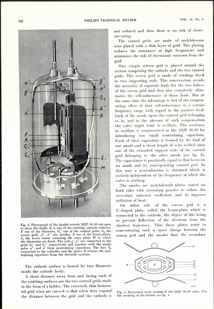
Fig. 3. Photograph of the double tetrode QQE 06/40 cut opento show the inside.K is one of the emitting cathode surfaces,F one of the filaments, G1' one of the control grids, G2 thescreen grid, A', A" the anodes, B one of the beam-plates,S1 the lower screen screening the mica plate M in whichthe electrodes are fixed. The rods g', gIf are connected to thegrids G1' and G1" respectively and together with ,the anodepoles a" and a' form neutralizing capacitors. The box S2connected to the cathodes and the plates B screens the neu-tralizing capacitors from the electrode systems.
The cathode surface is heated by two filamentsinside the cathode body.A short distance away from and facing each of
the emitting surfaces are the two control grids madein the form of a ladder. The extremely thin horizon-tal grid wires are curved so that when they expandthe distance between the grid and the cathode is
not reduced and thus there is no risk of short-circuiting.The control grids are made of molybdenum
wire plated with a thin layer of gold. This platingreduces the resistance at high frequencies andminimizes the risk of thermionic emission from thegrid.
One single screen grid is placed around thesystem comprising the cathode and the two controlgrids. This screen grid is made of windings fixedto two supporting rods. This construction avoidsthe necessity of separate leads for the two halvesof the screen grid and thus also completely elim-inates the self-inductance of those leads. But atthe same time the advantage is lost of the compen-sating effect of that self-inductance in a certainfrequency range with regard to the positive feed-back of the anode upon the control grid belongingto it, and in the absence of such compensationthe valve might tend to oscillate. This tendencyto oscillate is counteracted in the QQE 06/40 byintroducing two small neutralizing capacitors.Each of these capacitors is formed by the lead ofone anode and a short length of wire welded ontoone of the extended support rods of the controlgrid belonging to the other anode (see fig. 3).The capacitance is practically equal to that betweenan anode and its corresponding control griel. Inthis way a neutralization is obtained which isentirely independent of the frequency at which thevalve is working.
The anodes are molybdenum plates coated onboth sides with zirconium powder to reduce thesecondary emission coefficient and to improveradiation of heat.
On either side of the screen grid IS aU-shaped plate, called the beam-plate, which isconnected to the cathode, the object of this beingto prevent deflection of the electrons from theshortest trajectory. Thus these plates assist inconcentrating such a space charge between thescreen grid and the anodes that the secondary
-----L:__-----G2
~=----A"
62952
Fig. 4. Horizontal cross section of the QQE 06/40 valve. Forthe meaning of the letters see fig. 3.

DECEMBER 1950 TRANSMITTING VALVES ·FOR MOBILE INSTALLATIONS 163
electrons cannot reach the screen grid when theanode current is large.
Since the beam-plates prevent them fromfollowing long trajectories, all the electronshave about the same and the shortest possibletransit time. Without such a measure there wouldbe differences in transit time and at very highfrequencies these differences would adversely affectthe efficiency of the valve.As is the case with receiving valves, in the QQE
06/40 a mica disc is used for fixing the mutualpositions of the electrodes. This plate is screenedfrom the strong electric field of the anodes, so thatthere are practically no dielectric losses in themica, which again makes for good efficiency.
Except for the anodes, whose leads and support-ing rods pass through the top end of the hard-glassenvelope (fig. 3), the rest of the electrode systemis mounted on a base of sintered glass 10), into whichseven rods of molybdenum have been fused. Threeof these rods extend farther into the envelopethan the others and carry the screening of themica plate. This screening plate together with thebeam-plates welded onto it form a framework,in which the cathode and the grids are fixed.Thus an exceptionally rugged construction isobtained, which makes the valve resistant to severeshocks.
Electrical properties
As already mentioned, the cathode is heated bymeans of two filaments interconnected at one end.These filaments can be connected either in parallelor in series as required, in view of the fact thatsome motorcars have 6 V batteries while othershave batteries of 12 V; the total consumption isthus 6.3 V, 1.8 A or 12.6 V, 0.9 A respectively.
The D.C. anode voltage is max. 600 V at frequen-cies below 250 Mc/s, max. 400 V at frequenciesabove 300 Mc/s and max. 500 V in the intermediatefrequency range; the screen-grid voltage is 250 V.These voltages can be derived from a rotary con-verter or from a transformer working together witha vibrator. The dissipation of each of the anodesmay amount to 20 W and that of the screen gridto 7 W.
The input capacitance measured between thetwo control grids is about 6.7 pF, while the outputcapacitance between the two anodes is about 2.1 pF.The feed-back of each anode upon its correspon-
ding control grid is quite insignificant, thanks to the
10) E. G. Dorgelo, Sintered glass, Philips Techn. Rev. 8,2-7, 1946.
built-in neutralizing capacitors, so that the QQE06/40 cannot oscillate unless feedback is purposelyapplied externally. In amplifiers the absence of in-tern~l feedback ensures a high degree of stabilityOwing to the self-inductance and the resistanceof the cathode lead being extremely small, only asmall driving power is needed, which can be taken,for instance, from an EL 41 valve.
The highest frequency at which the QQE 06/40can still operate with a reasonable efficiency isabout 430 Mc/s (wavelength 0.70 m). It can workat still higher frequencies but then the power gainis no greater than that of an equivalent triode.
100
w,% H{,,~
t80
60
40
20
i 20
400 200
Il
3 4 _). Sm
1()() f- 6OMc/s6$605
Fig. 5. Output Wo and efficiency 7] 11) of the QQE 06/40 vah;eas functions of the wavelength ..1. and the frequency f.
Infig. 5 the output and the efficiency 11) have beenplotted as functions of the wavelength. It is seen,for instance, that at frequencies below 200 Mc/s90 W can be generated with an efficiency ofabout 75%, and that at a frequency of 300 Mc/sthese figures are 70 Wand 65% respectively.
The double tetrode QQC 04/15
Construction
In cases where a lower output suffices there isneed of a smaller and less expensive valve, and itis with a view to meeting this need that the QQC04/15 valve has been developed, an illustrationof which is given in fig. 6.
The construction is analogous to that of theQQE 06/40 in that the QQC 04/15 is likewise adouble tetrode with one screen grid common toboth the electrode systems (see the cross sectioninfig. 7).
11) As usual, here efficiency is understood to be the ratio ofthe output Wo to the D.C. power fed to the anodes.

164 PHILIPS TECHNICAL REVIEW VOL. 12, No. (>
Fig. 6. Photograph of the double tetrode QQC 04/15 cut opento show the inside. F' one of the directly heated cathodes,G/ one of the control grids, G2 screen grid, A', A" anodes,B beam-plates, M mica disc, V springs keeping the filamentsstretched.
One point of difference, however, lies in thecathodes, which in this construction are directlyheated and each consists of a V-shaped, oxide-coated filament. Such a cathode requires lessheating power than that needed for a correspon-ding indirectly-heated cathode, whilst also thethermal inertia is much less. The cathode of theQQC 04/15, which consumes 4.3 W, reaches itsworking temperature 1.5 seconds after switchingon, so that, in order to avoid unnecesary drainingof the battery, the filament current can quite wellbe switched offwhile the transmitter is not working.The two V-shaped filaments are connected in
series and the common point is connected to abase pin.A directly heated cathode causes a greater
input damping than an indirectly heated one,
anel for this reason it was not necessary to useneutralizing capacitors in the QQC 04/15, but onthe other hand a relatively larger driving poweris needed.
The envelope is made of soft glass. This, it istrue, cannot withstand such a high temperatureas the hard glass of the QQE 06/40, but it has theadvantage that the valve can be manufacturedon the machines equipped for the mass productionof receiving valves. Thus the QQC 04/15 has theappearance of a receiving valve (fig. 6), namelythat of one of the key type.
~ L A'G; 02
G Bai' A"Lr[L__
62953
Fig. 7. Horizontal cross section of the QQC 04/15 valve. F',F" cross section of the two V-shaped, directly heated cathodes,between which is a screen D. The other letters are as indicatedin fig. 4.
A difference compared with normal rece1vmgvalves lies in the base pins, which are of chromeiron and coated over their entire length with athin layer of copper, in such a way, of course, thatthe leads are vacuum-tight. The resistance of thislayer at very high frequencies is much less thanthat of non-coated pins 12).
The QQC 04/15 is well able to withstand themechanical shocks occurring in automobiles andtrains, just as well as the other valves used in thetransmitter and in the receiver.
Electrical properties
At a voltage of 6.3 V the filament current ofthe QQC 04/15 is 0.68 A. When a 12 V battery isused two of these valves can be connected in series.
The D.C. anode voltage is max. 400 V and thescreen-grid voltage 200 V. Each of the anodes hasa dissipation of 8 Wand the screen grid 7 W.When used in push-pull the QQC 04/15 has an
input capacitance of 5.7 pF and an outputcapacitance of 1.7 pF. The capacitance between ananode and its corresponding control grid is 0.05 pF.
12) Cf. K. Rodenhuis, Two triodes for reception of decirnetricwaves, Philips Techn. Rev'. 11, 79-89, 1949 (No. 3), inparticular p. 81.

DECEMBER 1950 TRANSMITTING VALVES FOR MOBILE INSTALLATIONS 165
25W 100 %
Wo
t20 80
15 60
10 40
5 20
2 4 ---...). Sm
Fig. 8. Output Wo and efficiency 1) 11) of the QQC04/15valveplotted as functions of the wavelength A and the frequencyf.
Fig. 8 shows the output and efficiency of thisvalve as functions of the wavelength. The outputat frequencies of 150 and 300 Mc/s, for instance,is respectively 22.5 Wand 9 W, with efficienciesof over 70% and 34%.
Mobile installations with the new valves
Philips' Telecommunication Industry (Hilver-sum, Holland) is turning out a mobile installation,type SRR 192, with the transmitter and the
Fig. 9. Mobile transmitter and receiver, type SRR 192, inthe boot of a motorcar.
receiver built together in a metal case that can becarried in the boot of a car (jig. 9). The controlpanel, the microphone and the loudspeaker aremounted in front of the driver's seat. The whole ofthe installation is tropic-proof.The transmitter has a QQE 06/40 as output
valve and offers the choice of two frequencieswithin a range of 300kc/soFrequency-multiplicationis obtained by means of three EF 42 valves andone EL 41 valve. Frequency modulation is applied.When this apparatus is used for a fixed station
it can be supplied from the A.C. mains. Betweentwo of these sets, one mobile and the other installedat a fixed point with an aerial 25 m above theground, in open country a range of 20 to 25 km canbe covered.
For further particulars reference is made to thearticle quoted in footnote 3).One of the authors of the present article (P.Z.)
has designed a smaller mobile installation whichlikewise works on the frequency-modulation systemand has a carrier frequency of 186.24 Mc/s 13).This employs four QQC04/15 valves, one of whichin the output stage and three for frequency multi-plication.
13) This design is fully describedin "QQC04/15Double Tetrodefor Mobile Transmitting Equipment", a technical publi-cation issued by the Electronic Tube Division of Philips,Eindhoven, Holland.
Summary. Following upon some introductory remarks con-cerning mobile radio stations such as are now being used forcommunication between automobiles or trains (mutuallyand with a fixed point), a description is given of two trans-mitting valves that have been specially developed for thispurpose. These are both double tetrodes (types QQE 06/40and QQC 04/15) in which the two electrode systems are soconstructed that the screengrids form mechanically one whole,by this means completely avoiding the complications arisingfrom stray self-inductance in separate screen-grid leads. Inan output stage the two electrode systems of a valve arepreferably used in push-pull. For frequency multiplicationthey can be connected in cascade. The QQE 06/40 type hasan indirectly-heated cathode of a special construction, owingto which only a very little driving power and thus few stagesare needed. Two built-in neutralizing capacitors provide forgood stability. The cathodes of the QQC 04/15 type of valveare directly heated and consequently there is little thermalinertia. At frequencies of 200Mc/s and below the QQE 06/40can generate 90 W with an efficiency of about 75%, and at300 Mc/s the output is 70 W with 65% efficiency. For theQQC 04/15 these figures are respectively about 22.5 W withover 70% and 9 W with 34% efficiency.


![RESEARCHARTICLE TheMagicalActivationofLeftAmygdala ......Introduction Literaryreading bringspleasures that areunique andimportanttohuman beings [1–3].Inter-estingly, part ofthese](https://img.pdfslide.us/doc/110x75/60d55f5c8dbfc8320e1615fe/researcharticle-themagicalactivationofleftamygdala-introduction-literaryreading.jpg)
![RESEARCHARTICLE …BIB_07FE0253499C.P001/REF.pdf · acutebrain injury(BI),nearly 20%ofpatients suffer fromDOC[6];themajority ofthese patients fallintoacoma,whichis associatedwith](https://img.pdfslide.us/doc/110x75/5aa3d65a7f8b9a2f048b681d/researcharticle-bib07fe0253499cp001refpdfacutebrain-injurybinearly-20ofpatients.jpg)