Embed Size (px)
Citation preview
LEADING THE SEARCH FOR NEW SOLUTIONS
4840 West Kearney Street, P. O. Box 2877Springfield, Missouri USA 65801-2877Tel 417 865-8715 800 825-6937 Fax 417 865-2950http://vacuum.tuthill.com
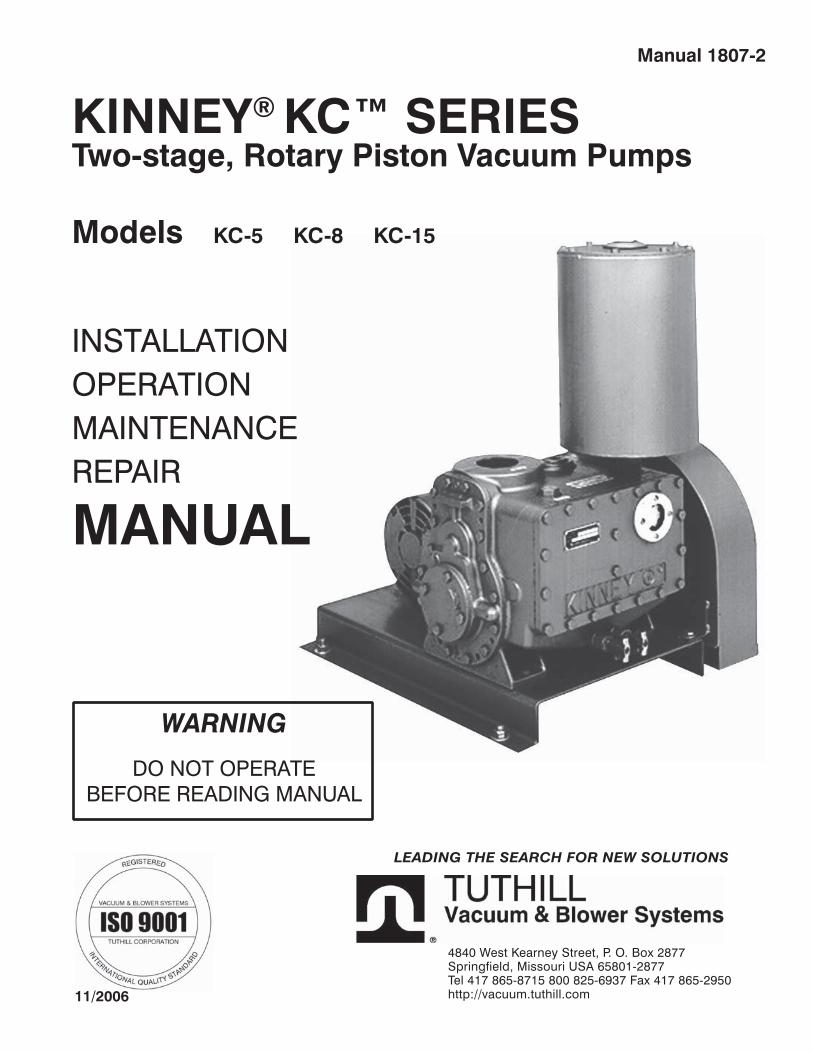
KINNEY® KC™ SERIESManual 1807-2
Two-stage, Rotary Piston Vacuum Pumps
Models KC-5 KC-8 KC-15
INSTALLATIONOPERATIONMAINTENANCEREPAIR
MANUAL
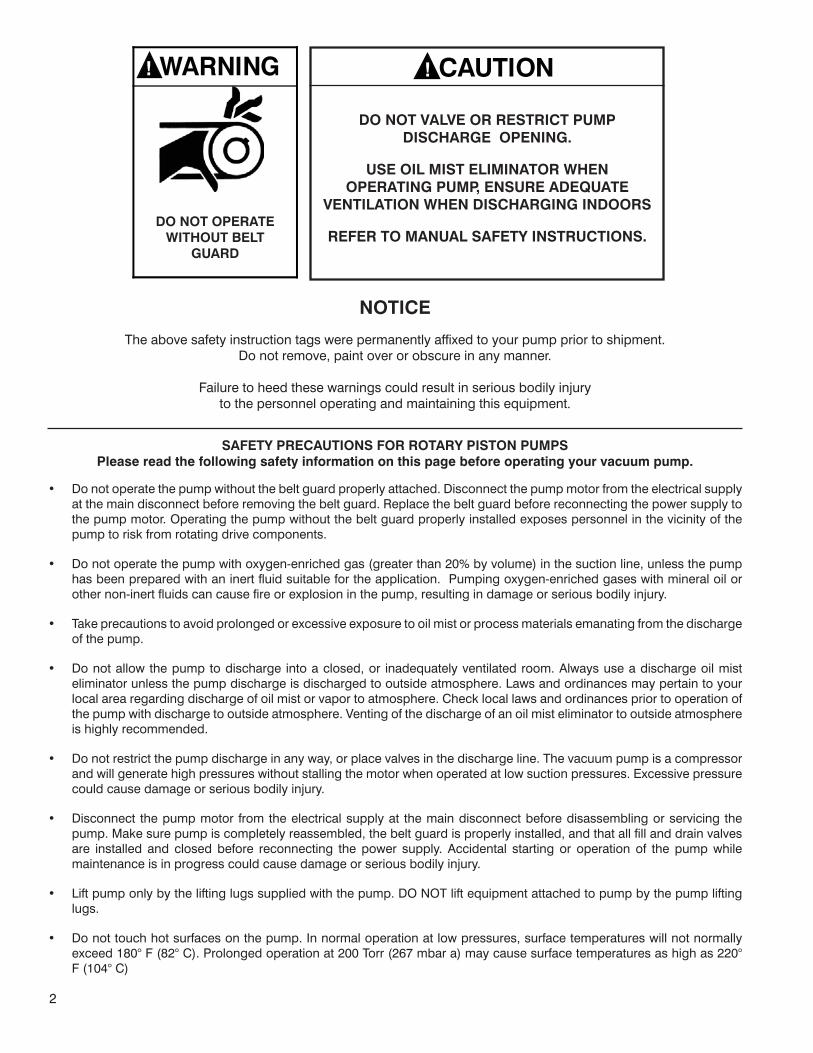
WARNING
DO NOT OPERATEBEFORE READING MANUAL
11/2006
2
SAFETY PRECAUTIONS FOR ROTARY PISTON PUMPSPlease read the following safety information on this page before operating your vacuum pump.
NOTICE
The above safety instruction tags were permanently affixed to your pump prior to shipment. Do not remove, paint over or obscure in any manner.
Failure to heed these warnings could result in serious bodily injury to the personnel operating and maintaining this equipment.
Do not operate the pump without the belt guard properly attached. Disconnect the pump motor from the electrical supply at the main disconnect before removing the belt guard. Replace the belt guard before reconnecting the power supply to the pump motor. Operating the pump without the belt guard properly installed exposes personnel in the vicinity of the pump to risk from rotating drive components.
Do not operate the pump with oxygen-enriched gas (greater than 20% by volume) in the suction line, unless the pump has been prepared with an inert fluid suitable for the application. Pumping oxygen-enriched gases with mineral oil or other non-inert fluids can cause fire or explosion in the pump, resulting in damage or serious bodily injury.
Take precautions to avoid prolonged or excessive exposure to oil mist or process materials emanating from the discharge of the pump.
Do not allow the pump to discharge into a closed, or inadequately ventilated room. Always use a discharge oil mist eliminator unless the pump discharge is discharged to outside atmosphere. Laws and ordinances may pertain to your local area regarding discharge of oil mist or vapor to atmosphere. Check local laws and ordinances prior to operation of the pump with discharge to outside atmosphere. Venting of the discharge of an oil mist eliminator to outside atmosphere is highly recommended.
Do not restrict the pump discharge in any way, or place valves in the discharge line. The vacuum pump is a compressor and will generate high pressures without stalling the motor when operated at low suction pressures. Excessive pressure could cause damage or serious bodily injury.
Disconnect the pump motor from the electrical supply at the main disconnect before disassembling or servicing the pump. Make sure pump is completely reassembled, the belt guard is properly installed, and that all fill and drain valves are installed and closed before reconnecting the power supply. Accidental starting or operation of the pump while maintenance is in progress could cause damage or serious bodily injury.
Lift pump only by the lifting lugs supplied with the pump. DO NOT lift equipment attached to pump by the pump lifting lugs.
Do not touch hot surfaces on the pump. In normal operation at low pressures, surface temperatures will not normally exceed 180° F (82° C). Prolonged operation at 200 Torr (267 mbar a) may cause surface temperatures as high as 220° F (104° C)
•
•
•
•
•
•
•
•
! WARNING
DO NOT OPERATEWITHOUT BELT
GUARD
DO NOT VALVE OR RESTRICT PUMP DISCHARGE OPENING.
USE OIL MIST ELIMINATOR WHEN OPERATING PUMP, ENSURE ADEQUATE
VENTILATION WHEN DISCHARGING INDOORS
REFER TO MANUAL SAFETY INSTRUCTIONS.
! CAUTION
3
TABLE OF CONTENTS
SECTION PAGESAFETY PRECAUTIONS AND WARNINGS 2INTRODUCTION 4OPERATING DATA 4DESCRIPTION 5
General 5Pump Components 5Operating Cycle 5Sealing and Lubrication 6Oil Types 6Specifications Table 6
INSTALLATION 7Mounting 7V-Belt Drive 7Discharge Piping 7Vacuum Piping 7Vacuum Gauges 8Electrical Connections 8General 8Filling the Pump with Oil 8Prestart Checks 9
OPERATION 9Starting the Pump 9Stopping the Pump 9Gas Ballast 10Special Refrigeration Service Units 10
MAINTENANCE 11Pump Periodic Maintenance 11Changing the Oil 11Flooding 11Oil Mist Eliminator 11Stalling 12
TROUBLESHOOTING 13Checking Pump Performance 13Pump Leaks 14Checking Process Equipment 14Process Equipment Leaks 14Leak Checking Techniques 15Oil Contamination 15Discharge Valve 15Shaft Seal 16
DISASSEMBLY 17REASSEMBLY 18REPLACEMENT PARTS 19PARTS LISTS & EXPLODED VIEWS 20
KC-5/KC-8 20, 21KC-8C 22, 23KC-15D 24, 25KC-15L 26, 27
WARRANTY STATEMENT 28

4
INTRODUCTION
CONGRATULATIONS on your purchase of a new KINNEY® KC™ Two-stage, Rotary Piston Vacuum Pump from Tuthill Vacuum & Blower Systems. Please examine the pump for shipping damage, and if any damage is found, report it immediately to the carrier. If the blower is to be installed at a later date make sure it is stored in a clean, dry location and rotated regularly. Make sure covers are kept on all openings. If blower is stored outdoors be sure to protect it from weather and corrosion.
KINNEY KC vacuum pumps are built to exacting standards and if properly installed and maintained will provide many years of reliable service. We urge you to take time to read and follow every step of these instructions when installing and maintaining your blower. We have tried to make these instructions as straightforward as possible. We realize getting any new piece of equipment up and running in as little time as possible is imperative to production.
WARNING: Serious injury can result from operating or repairing this machine without first reading the service manual and taking adequate safety precautions.
IMPORTANT: Record the pump model and serial numbers in the OPERATING DATA form below. You will save time and expense by including this reference identification on any replacement part orders, or if you require service or application assistance.
OPERATING DATA
It is to the user’s advantage to have the requested data filled in below and available in the event a problem should develop in the blower or the system. This information is also helpful when ordering spare parts.
Model No. V-Belt Size Length
Serial No. Type of Lubrication:
Startup Date
Pump RPM Operating Vacuum
Pump Sheave Diameter Any other special accessories supplied or in use:
Motor Sheave Diameter
Motor RPM HP
NOTES:
(Recorded from nameplate on unit)

5
KINNEY® KC™ SERIES MANUAL 1807-2© 2006, Tuthill Corporation
DESCRIPTION
GENERAL
The KC series of compound high vacuum pumps covered by these instructions consist of two basic pump groups, models: • KC-5 AND KC-8 • KC-15
The pumps within each of the first two groups are identical except for the motor and v-belt drive, which are changed to give different rotational speeds. Specifically, the models KC-5 and KC-8 are the same except that the KC-8 is driven faster.
Each Kinney KC pump is an air-cooled rotary piston high vacuum pump consisting of two rotary piston pumping stages, which operate, in series. These pumps attain low ultimate pressures of less than 2 x 10⁻⁴ Torr (McLeod gauge). The rugged, simple design ensures dependable service under the most severe applications without costly or complicated maintenance. All components are easily serviced and no special tools are required. Reliable, leak-free shaft seals require no adjustments or maintenance.
Each pump is equipped with a gas ballast valve, which regulates the vapor handling capacity of the pump. Gas ballast aids in increasing the operation period between oil changes by preventing oil contamination by most condensable vapors. It can also be used to clean the oil once it has become contaminated. Use of gas ballast will also reduce pump operating noise.
A combination oil separator and oil mist eliminator is used in place of a conventional design oil separator. This unit provides thorough filtering of the pump exhaust and results in a cleaner pump area, without expensive and space consuming exhaust piping systems.
Pump specifications are shown in Figure 2 on page 7.
PUMP COMPONENTS
Each pump basically consists of two rotary piston pumping stages connected in series - a high vacuum stage and a backing stage. The two rotary pistons are driven by two eccentric cams keyed to a common shaft. Each rotary piston has a hollow extension (slid) that moves through a slide pin and leads to the inlet of the particular pumping stage. Ports are cast into the inlet side of each piston and these ports together with the slide pins form automatic inlet valves.The two pumping stages are connected in series by an internal duct and are enclosed in a single cylinder. The ends of the cylinder are enclosed by an open head, through which the shaft extends, and a closed head. The open head contains a shaft seal to prevent leakage along the shaft.
A spring loaded discharge valve is located at the discharge side of the backing stage (on the open head end of the pump). An oil mist eliminator is mounted above the backing stage.
A sight gauge is provided for checking the oil level in the pump. When operating at low inlet pressure, the level should be in the center of the sight gauge. Note that the oil level will change with large changes in pump inlet pressure.
OPERATING CYCLE
The operating cycle is shown in diagram form in Figure 1. Gas from the system enters through the pump inlet. It passes through the hollow piston slide and out through the piston slide port into the space being created between the piston and cylinder wall. As the piston rotates, this space increases and more gas is drawn in. At the same time, the gas taken in and trapped on the previous revolution is on the compression side of the piston and slide where it is compressed and discharged into the cored passageway that leads to the inlet of the backing stage.
The rotary piston pumping cycle is repeated in the backing stage. The gas is compressed and forced out through the discharge valves along with a small amount of oil and then into the oil mist eliminator where the oil is separated from the gas. The gas is discharged to atmosphere and the oil drains back to the reservoir.
6
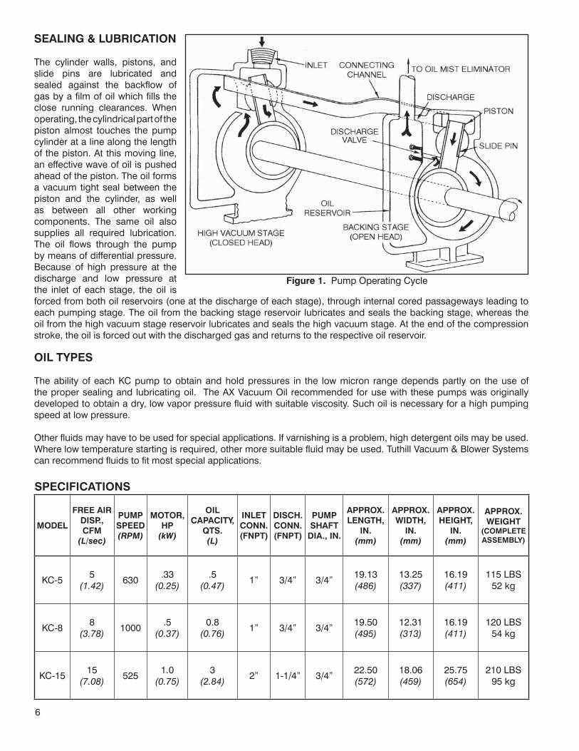
SEALING & LUBRICATION
The cylinder walls, pistons, and slide pins are lubricated and sealed against the backflow of gas by a film of oil which fills the close running clearances. When operating, the cylindrical part of the piston almost touches the pump cylinder at a line along the length of the piston. At this moving line, an effective wave of oil is pushed ahead of the piston. The oil forms a vacuum tight seal between the piston and the cylinder, as well as between all other working components. The same oil also supplies all required lubrication. The oil flows through the pump by means of differential pressure. Because of high pressure at the discharge and low pressure at the inlet of each stage, the oil is forced from both oil reservoirs (one at the discharge of each stage), through internal cored passageways leading to each pumping stage. The oil from the backing stage reservoir lubricates and seals the backing stage, whereas the oil from the high vacuum stage reservoir lubricates and seals the high vacuum stage. At the end of the compression stroke, the oil is forced out with the discharged gas and returns to the respective oil reservoir.
OIL TYPES
The ability of each KC pump to obtain and hold pressures in the low micron range depends partly on the use of the proper sealing and lubricating oil. The AX Vacuum Oil recommended for use with these pumps was originally developed to obtain a dry, low vapor pressure fluid with suitable viscosity. Such oil is necessary for a high pumping speed at low pressure.
Other fluids may have to be used for special applications. If varnishing is a problem, high detergent oils may be used. Where low temperature starting is required, other more suitable fluid may be used. Tuthill Vacuum & Blower Systems can recommend fluids to fit most special applications.
SPECIFICATIONS
MODEL
FREE AIR DISP., CFM
(L/sec)
PUMP SPEED (RPM)
MOTOR,HP
(kW)
OILCAPACITY,
QTS.(L)
INLETCONN.(FNPT)
DISCH.CONN.(FNPT)
PUMPSHAFT
DIA., IN.
APPROX.LENGTH,
IN.(mm)
APPROX. WIDTH,
IN.(mm)
APPROX.HEIGHT,
IN.(mm)
APPROX. WEIGHT
(COMPLETEASSEMBLY)
KC-55
(1.42)630
.33(0.25)
.5(0.47)
1” 3/4” 3/4”19.13(486)
13.25(337)
16.19(411)
115 LBS52 kg
KC-88
(3.78)1000
.5(0.37)
0.8(0.76)
1” 3/4” 3/4”19.50(495)
12.31(313)
16.19(411)
120 LBS54 kg
KC-1515
(7.08)525
1.0(0.75)
3(2.84)
2” 1-1/4” 3/4”22.50(572)
18.06(459)
25.75(654)
210 LBS95 kg
Figure 1. Pump Operating Cycle

7
INSTALLATION
MOUNTING
If only a bare shaft pump has been supplied, mount it on a level, rigid base. Connect it to a motor and operate it at the rotational speed shown in the specification chart. Wire the motor so that the direction of the shaft rotation is as shown by the arrow cast on the pump. On standard units, this is clockwise when facing the pump pulley.
V-BELT
When installing a V-belt drive, loosen the motor mounting screws and slide the motor towards the pump. Position the v-belt on the pulleys. Move the motor away from the pump to tighten the drive.
Check the tension of the V-belt drive by applying normal thumb pressure to the top of the V-belt midway between the two pulleys. Note that the tightest belt should not depress more than its own thickness. Adjust the belt tension as required, but do not over-tighten or under-tighten the drive. A general rule for correct V-belt tension is to tighten the drive just enough to prevent slippage when operating at full load, (that is, with the pump gas ballast valve fully opened). Recheck the tension of the V-belts after the first 48 hours of operation.
DISCHARGE PIPING
If desired, connect discharge piping to the discharge fitting on top of the oil mist eliminator to vent or reclaim the exhaust gases.
When connecting the discharge piping, use a dropout trap at the connection to the oil mist eliminator. Otherwise, condensate from the discharge piping will drip back into the oil separator and may contaminate the oil.
A simple dropout trap consists of a tee equipped with a drain cock for condensate removal. Place a flexible connection, possibly rubber hose, at the discharge of the pump to eliminate a rigid connection and to provide a convenient disconnect point for servicing. Turn down the outside end of the discharge line to prevent entry of rain.
VACUUM PIPING
The vacuum piping to the pump inlet should be as large and as short as possible. Use manifolding that is no smaller than the pump inlet. It is recommended that the inlet manifolding be arranged to prevent oil migration back into the system. See Figure 3 for recommended arrangements of vacuum manifolding with integral oil baffles.
As with all rotary mechanical pumps, it is best to install a flexible member in the suction manifold of the pump to avoid alignment problems and to reduce the possibility of transmitting vibration to and from other components. Self-supporting bellows type flexible connectors are recommended and are available from Tuthill Vacuum & Blower Systems.
Figure 3. Vacuum Manifolding with Integral Oil Baffles

8
Other types may be too hard and transmit vibration, or too soft and may exert considerable force on the pump and piping when collapsing under atmospheric pressure. Pour a small quantity of oil into the pump suction before connecting the inlet piping to ensure proper lubrication at initial start-up.
Make all inlet connections vacuum tight. As a check, note that the pressure at the end of the connecting manifold should be very close to that obtained with the pump inlet blanked-off. All demountable joints should be O-ring sealed.
If threaded connections are used, clean the threads and turn them together about two turns. Cover the remaining exposed threads with a sealing compound such as Loctite 567 or Teflon Tape for piping up to 1” in diameter. Use Titeseal (Radiator Specialty Company, North Carolina), on large pipe sizes. Screw the joint together tightly.
Install a vacuum isolation valve between the system and the pump with a means for connecting a vacuum gauge on both sides of the valve and an air admittance valve on the pump side of the isolation valve. With such an arrangement, it is possible to check either the system or the pump for leaks without disconnecting the vacuum piping. This isolation valve will also allow the system to be kept under vacuum while the pump is not running, or the pump operating while the system is open to atmospheric pressure.
VACUUM GAUGES
Two general types of vacuum gauges are used for the testing of vacuum equipment, total pressure reading types, such as Thermistor or Thermocouple gauges, and partial pressure reading McLeod gauges. The McLeod gauge indicates the partial pressure of permanent gases. It does not indicate the component of pressure due to condensable gases such as water vapor. It is not greatly affected by vapor contamination unless the contamination pressure is quite high. It is most useful in confirming pump performance and for determining the absence or presence of real leaks. Thermistor or Thermocouple gauges are preferable for leak checking and indicating the degree of contamination.
A high Thermistor or Thermocouple gauge reading may indicate that the pump is contaminated, that it leaks, or both. A high McLeod gauge reading means that a real leak is present.
WARNING: Disconnect pump from electrical power source prior to making repairs or adjustments to any electric component of the unit.
ELECTRICAL CONNECTIONS
Check the operating voltage of the motor by comparing the lead connections with the markings on the motor. Connect it to the proper power source through necessary switching and safety equipment. After wiring is complete, momentarily start and stop the motor to check the direction of rotation against the arrow cast on the pump. If it rotates in the wrong direction, change the motor windings as indicated in the motor instructions. (These are generally printed on the connections cover plate.) Note that standard pumps rotate clockwise when facing the pump pulley.
WARNINGS:When operating the pump in an enclosed area it is necessary, for health reasons, to have the area well ventilated. If ventilation is not adequate, the pump discharge should be filtered or piped to open air.Do not block or restrict the flow of gas from the pump discharge. Back pressure could cause severe damageThe belt guard must be properly secured to the pump at all times while the pump is running.
GENERAL
Kinney KC Model pumps are designed for low-pressure operation. They are generally not suitable for prolonged periods of operation at high pressures. Each pump has been thoroughly tested and is ready for operation as soon as it is installed and filled with oil. If the vacuum system is tight, including the connections to the pump, the ultimate system pressure should be close to that obtained with the pump inlet closed off.
FILLING THE PUMP WITH OIL
Refer to the specifications chart for the quantity of oil required for the particular pump. On initial startup, pour a small quantity of oil into the pump inlet to insure adequate lubrication on starting. Pour the remainder of the required oil quantity into the pump as follows:
•
•
•

9
On the KC-5, KC-8 and KC-15, unscrew the oil mist eliminator from the pump. Remove the high vacuum stage oil fill plug. Pour approximately one-third of the required quantity of oil into the high vacuum stage of the pump. Pour the remaining quantity of oil through the threaded hole from which the oil mist eliminator was removed. Check that the fill plug and gasket are clean and in good condition. Replace the plug and gasket, making a vacuum tight seal. Replace the oil mist eliminator on the pump.
PRE-START CHECKS
Check that the suction lines are tight and absolutely free of all foreign matter.
Check that the pump has been filled with oil.
Check that the pump can be turned over by hand without mechanical interference. Note that the inlet should be open to atmospheric pressure and that additional turning force is required when the pump discharges.
Check the v-belt tension by applying normal thumb pressure to the top of the tightest belt about midway between the two pulleys. The tightest belt should depress about its own thickness indicating proper tension. In general, v-belts should be tightened just enough to prevent slippage when operating the pump under load (that is, operating with a fully open gas ballast valve).
Check that all wiring is completed and correct. Momentarily, start and stop the pump to check the direction of pump shaft rotation. On standard pumps, it should be clockwise facing the pump pulley.
OPERATION
STARTING THE PUMP
Perform the pre-start checks as indicated previously. Note that the minimum starting temperature is 50°F.
Depress the motor start switch to start the pump. It is recommended that the pump be warmed up before starting process work. This requires operation for about 10 minutes with the pump isolated from the process equipment.
Open the pump isolation valve, if one is provided, allowing the pump to evacuate the process equipment.
To reduce the operating sound of the pump, slightly open the gas ballast valve. This is a preferred method of operation since it helps to keep the oil clean.
Note that the oil level should change when operating the pump at high and low inlet pressures. This indicates proper oil flow through the pump. When the pump is first started, the oil level will rise in the backing stage. When the inlet pressure is reduced to the micron (10-3 Torr) range, the oil level will drop to about the center of the sight glass.
If the pump is used in an application where excessive amounts of water vapor are encountered, remove the mist eliminator element to prevent condensation. Periodically stop the pump and open the backing stage oil drain to drain out water accumulation. Drain out all water accumulation each time before starting the pump, because if the water level rises above the oil inlet port, the pump may be damaged on start up.
STOPPING THE PUMP
If a vacuum valve is provided between the pump and the process equipment, place this valve in the closed position.
Vent the pump suction to atmospheric pressure by opening a vent valve. Turn off the power to the pump motor. Note that if the system does not have a pump isolation valve, vent the system to atmospheric pressure to prevent oil from being drawn into the vacuum system. Oil flooding of the pump cylinder could make restarting difficult. Note that a solenoid operated air inlet vent valve is offered as an accessory on the Model KC-15 pump. This valve is wired across the motor so that it will automatically open to vent the pump inlet when the pump power is turned off. Note that this valve is adequate for venting only a small volume. It is not large enough to vent an attached system.
1.
2.
3.
4.
5.
1.
2.
3.
4.
5.
1.
2.

10
GAS BALLAST
Gas ballast is an operating mechanism, which is used to prevent the condensation of vapor in a vacuum pump. Vapor present in the gas being pumped can condense during the vacuum pump compression cycle and mix with the vacuum pump oil. Since this oil is recirculated through the pump, the condensate is carried with the oil and allowed to re-evaporate, causing poor pump performance and making frequent oil changes necessary. By using gas ballast, most vapors can be passed through a vacuum pump without condensing and then discharged with the pump exhaust.In addition to preventing vapor condensation, the use of gas ballast also reduces discharge valve noise to a low level. It is generally possible to eliminate valve noise with a small gas ballast flow, which does not seriously increase the ultimate pressure. If the ultimate pressure is tolerable, this is a preferred method of operating since it also helps to keep the oil clean.
The setting of the gas ballast valve is best determined by trial and error because the amount of condensable vapor, as well as the system operating conditions, vary with different processes. In addition, the motor power consumption and the ultimate pressure increase in proportion to the gas ballast airflow.
To use the gas ballast technique, proceed as follows:
Continuous gas ballast. With the pump operating, open the gas ballast valve until the ultimate pressure is slightly below that needed for the process. Operate the pump in this manner continuously to aid in preventing oil contamination.
Intermittent gas ballast. With the pump operating, fully open the gas ballast valve during periods when this will not affect the process (work preparation, recycling, etc.). This will aid in cleaning up oil contamination. If not inconvenient, operate the pump in this manner overnight to clean up badly contaminated oil.
If it is necessary to clean up the oil in the shortest period, the length of time needed can be estimated as follows: Observe the pump’s blank-off pressure with the gas ballast valve fully closed. Open the gas ballast valve fully and operate the pump for a short period (15 to 20 minutes). Close the gas ballast valve fully and observe the pressure change in that time period.
Use this as a rough guide to estimate the total time required to obtain the desired blank-off pressure. The oil is clean when there is no further reduction in pressure.
SPECIAL REFRIGERATION SERVICE UNITS
Kinney offers high vacuum pumps that are specifically engineered for servicing refrigeration equipment, which includes thorough vacuum drying, degassing, and fast leak detection.
When connecting a pump to a refrigeration unit, use 1/2”, 5/8”, or 3/4” copper tubing.
1.
2.
Figure 4. Identification of Pump Components

11
Smaller tubing is not recommended because of the restriction to gas flow. If it is necessary to vent the pump exhaust outside, use ordinary hose of suitable diameter. Do not position the hose so that condensate can collect and cause blockage, such as in a loop or sag in the hose.
Before and after using a pump on refrigeration equipment, remove the cap in the drop-out trap to drain all liquid condensate. Drain the pump, flush, and recharge it with fresh oil each time after using it, if the pump will not be used again for two or three days. This will protect the pump during storage from rust and contaminants, which are frequently encountered in this type of pump service.
MAINTENANCE
PUMP PERIODIC MAINTENANCE
Check the oil level daily for the first week of operation and weekly thereafter. The oil level should be about midway on the sight gauge when operating at low inlet pressures. However, the oil level will change with large changes in pump inlet pressure. If there are no changes in the oil level, check for obstructed oil passages. Check the condition of the oil periodically by draining a small quantity of oil into a clean container and visually inspecting it for solid or liquid contaminants. Change the oil when contaminated. There is no fixed interval for changing the pump oil, since applications vary widely. This can be determined only by experience or deterioration of pump performance. As a minimum, the pump oil should be changed after each three-month operating (not storage or idle) period.
CHANGING THE OIL
All moisture as well as other vapors present in the system will be drawn into the pump. Some may be condensed and will collect in the backing stage oil reservoir; contaminating the pump oil and causing poor pump performance. Proper use of gas ballast will minimize the amount of condensate and reduce the frequency of oil changes.
Change the oil when it becomes contaminated with foreign matter or with chemicals. The period between changes can be best determined by the user for his particular operation.
To drain the oil, remove both drain plugs on the side of the cylinder.
If drain valves are provided, open both drain valves.
To clear all of the oil out of the cylinder, open the pump inlet (suction) to atmosphere. Turn the pump over a few revolutions to drive the oil out of the cylinder.
Replace the drain plugs.
Fill the pump with oil as directed under the OPERATION section per Filling The Pump With Oil.
NOTE: that if the oil is badly contaminated, it may be necessary to flush the pump by changing the oil several times, with a short period of operation between each change to check the pump’s blank-off pressure.
FLOODING
If the pump is not vented to atmosphere when stopped under vacuum, it is possible for oil to flood the pump cylinder causing a hydraulic lock. When this occurs, difficulty may be experienced in starting the pump. To release this lock, fully open the gas ballast valve and try to turn or rock the pump pulley by hand to force out the oil. Do not apply excessive force to turn the pump pulley (such as with a long pry bar).
OIL MIST ELIMINATOR
It may be necessary to clean out the oil separator or change the replaceable filter element after the pump has been in service for a long period, or quite frequently if mechanical contaminants are present, or if oil sludging due to chemical attack takes place. To do this, remove the top cover of the oil separator and clean it as required.
Since pump applications vary greatly, operating experience is the best guide when determining the interval for replacing the oil mist eliminator element. NOTE: Drain valves in the OME are application-specific.
1.
2.
3.
4.
5.

12
Change the oil mist eliminator if:
Visual inspection shows the oil mist eliminator element to be blocked by foreign matter.
Pump back pressure as read at inlet to the oil mist eliminator (or the oil fill plug) reads over 4 to 6 PSIG (275 to 400 mbar g). This indicates element is contaminated.
Motor current exceeds manufacturer’s recommendations shown on motor nameplate. This indicates element is contaminated.
Mist discharged from the oil mist eliminator. This indicates element is ruptured or gasket is not sealing.
Flooding of the oil separator-mist eliminator assembly can happen if the pump is operated for prolonged periods above 5 Torr (6.7 mbar a). This oil buildup will cause oil droplets to be discharged when the pump is operating. To remove this trapped oil, lower the pump operating pressure below 5 Torr (6.7 mbar a) until the trapped oil can return to the pump.
If it is not feasible to operate the pump at 5 Torr (6.7 mbar a) or below to prevent flooding the oil separator-mist eliminator assembly, then an oil return line should be installed, see Figure 5 below. If the pump operating range is 5 to 150 Torr (6.7 to 200 mbar a), the return line should connect to the gas ballast valve in which case the valve must not be closed. If the operating range is above 150 Torr (200 mbar a) the oil return line should connect to the pump at the suction port area.
STALLING
If the pump stalls at any time it may be due to loose belt, lack of lubrication or foreign matter in the pump. If the pump cannot be turned over by hand after cooling down, the pump must be cleaned. Cleaning and inspection of the pump is covered in the disassembly section.
1.
2.
3.
4.
Figure 5. Oil Return Line
Figure 6. Breakdown of Common Faults in Vacuum Systems
* Pressure rises due to internal causes such as contaminationby high vapor pressure materials outgassing from associated
equipment work, and leaking from trapped volumes of air.
System notOperating
Pressure notAttainable
AssociatedProcess
Equipment
VacuumPump
Virtual Leaks*
Leaks
Operator ErrorContamination
LeaksMalfunctions

13
TROUBLESHOOTING
Although KINNEY® KC™ rotary piston vacuum pumps are well-designed and manufactured, problems may occur due to normal wear and the need for readjustment. The chart below lists symptoms that may occur along with probable causes and remedies.
SYMPTOM PROBABLE CAUSE REMEDY
System ultimate pressure
excessively high
Process equipment faulty. Vacuum pump improperly operating or malfunctioning
Check pump performance. See “Checking Pump Performance”.
Process equipment contaminated by high vapor pressure material.
Clean equipment with acetone, alcohol, or either.
Pump down with vacuum pump overnight.
Process equipment leaks. Leak check process equipment. See “ Process Equipment Leaks”.
Improper vacuum pump oil flow. Clean oil ducts.
Vacuum pump oil contaminated. Change pump oil, see “Changing the Oil” & “Oil Contamination”
Discharge valves malfunctioning. Check valves per “Discharge Valves”.
Vacuum pump leaks. Leak check pump per “Pump Leaks”.
Vacuum pump shaft seal malfunctioning Check shaft seal per “Shaft Seal”.
Vacuum pump internal parts worn or damaged.
Disassemble pump and inspect internal part. See “Disassembly”.
Excessive pump noiseat low pressures. Hydraulic noise of pump discharge. Open gas ballast valve.
Pump stalls.
Electrical power loss. Check power at pump.
Pump malfunctioning. Pump oil contaminated or pump is insufficiently lubricated.
See “Stalling”. Refer to maintenance paragraphs on “V-Belt Drive” and “ “Changing the Oil”.
Pump discharge line blocked. Clear pump discharge line. Check oil mist eliminator element for blockage.
Pump will not start.
Electrical failure. Check for power at pump. Check motor start controls and motor.
Pump flooded with oil. Clear oil from pump by turning over by hand or disassembling the pump. See “Flooding”.
Temperature excessively low. Heat pump to minimum starting temperature of 50° F (10° C).
Oil discharged from oil mist
eliminator.
Excess oil on discharge side of oil mist eliminator.
Unscrew oil mist eliminator and pour oil through the discharge fitting back into the pump.
As an alternative, on KC-5, KC-8 and KC-15 pump reduce pump inlet pressure below 10 Torr to allow collected oil to drain back through the integral check valve in the oil mist eliminator.
CHECKING PUMP PERFORMANCE
If the processing time increases or the ultimate pressure becomes poor with no recent changes in the process or in the system configuration, test the pump to determine if the trouble is in the pump or the connected process equipment. To check the condition of the pump, measure the blank-off pressure ads directed below using a McLeod gauge.
If possible, also read the blank-off pressure with a thermistor or thermocouple gauge. Refer to Figure 6 on page 13 and the Troubleshooting chart on page 14 for a listing of common faults in vacuum systems. Figure 7. Pump Test Manifolding

14
To read the pump blank-off pressure:
Close off the pump inlet by means of a vacuum valve or short segment of manifolding as shown in Figure 8.
Connect a vacuum gauge to the pump side of the valve or manifolding. Position the gauge connection so that it will not become flooded or blocked by splashing pump oil.
Operate the pump for a short period, about 15 minutes, until the lowest pressure is reached. Note the reading obtained.
The reading obtained should be between the pump’s specification blank-off pressure (low end) and the pressure needed for the process (high end). Average blank-off readings are 0.5 to 2.0 microns with a McLeod gauge reading.
Note that for practical consideration, pumps need not obtain pressures lower than 90% of the required operating pressure to be usable. If the McLeod gauge reading is low and the Thermocouple gauge reading is high, the pump oil is contaminated. Change the oil and re-check the pump blank-off pressure. (In some instances it is necessary to change the oil several times to flush all traces of contamination from the pump.) Note that if a Thermocouple gauge is not available and the pump oil has been in service for an appreciable period, it is best to change the pump oil several times to eliminate pump oil contamination as a possible cause of poor pump performance. After changing the oil, re-check the blank-off pressure.
If both the McLeod and Thermocouple gauge readings are high, indication that the oil is not contaminated, the pump is leaking. Proceed as directed in “Pump Leaks”.
PUMP LEAKS
If the pump is suspected of leaking (after eliminating oil contamination as the cause of poor performance), use a plastic sealing compound, such as Apiezon Q, to seal over suspected areas, and check pump blank-off performance before making permanent repairs with Loctite 515. If gasketed connections are suspected, remake the connections with temporary gaskets of plastic sealing compound; these should not be made too thick since the material may be squeezed into the equipment.
Check carefully around the head-to-cylinder joints, securing bolts, plugs, shaft seal housing joints, and generally any penetration into the vacuum pumping portion of the pump. Check the shaft seal for mechanical defects, such as a cracked carbon washer or hardened rubber components.
CHECKING PROCESS EQUIPMENT
If the blank-off test shows that the vacuum pump is functioning properly but that the process equipment is faulty, the trouble can be isolated further by applying the following procedures:
Pump down each segment of the process equipment individually, starting at the segment closest to the vacuum pump.
Check the lowest pressure attainable when each segment is added. If the pressure is close to that obtained previously, add the next segment. If the pressure is not, leak test the last segment. When leak checking process chambers, start at the air and gas inlet valves, doors, sight ports, electrical and mechanical feedthroughs, gauge tube fittings, and any other penetrations, especially threaded, gasketed and o-ring connections. After a suspected leak has been found, cover it with plastic sealing compound, such as Apiezon® Q, and check the equipment performance before sealing the leak permanently. Thus, all permanent repairs can be made at the same time.
PROCESS EQUIPMENT LEAKS
Attach a vacuum gauge to the connection on the system side of the vacuum valve. For this test, clear the system of any process work, which might give off vapors and change the reading. Run the pump to obtain the lowest possible pressure and close the valve. Observe the pressure rise. If the pressure rise is greater than desired, or if the ultimate pressure is too high, check and eliminate all leaks. Check the system carefully for loose joints and obvious leaks. Use a leak detector if available. If a leak detector is not available, proceed as directed in “Leak Checking Techniques” below.
1.
2.
3.
1.
2.

15
LEAK CHECKING TECHNIQUES
If a leak detector is not available, use the following methods to locate leaks:
Cover suspected leaks with a low vapor pressure sealing compound such as Apiezon Q, Duct Seal or Plasticine®.
Do this while pumping on the equipment and monitoring the pressure. A sudden decrease in pressure indicates that a leak has been covered. Repair leaks permanently as necessary.
If the leak is large, causing pressures in the Torr range, pressurize the process equipment with one PSIG of clean compressed air and paint a soap solution on suspected leak areas. Bubbles indicate leaks. De-energize and isolate the pump during the leak checking. Repair leaks as required.
If the leak is small, causing pressures in the sub Torr range, use a fast acting thermocouple or thermistor gauge in conjunction with a probing medium such as acetone, alcohol, or helium. Position the vacuum gauge head downstream from the suspected leak area, between the leak and the pump. When the pressure has been reduced so that the gauge may be used, apply probing medium to suspected leak areas. (A squirt gun or brush may be used for applying liquid probing media.) If the probing fluid is directed at the leak or an area close to it, a sudden change in pressure will occur. Cover suspected leaks with plastic sealing compound and continue leak checking until the desired pressure is obtained.
If leak checking fails, disassemble and remake all demountable joints and connections using new gaskets or vacuum sealing compound such as Loctite 515. Temporary gaskets may be fabricated from plastic sealing compound but these should not be made too thick since the material may be squeezed into the equipment.
OIL CONTAMINATION
When the pressure has been satisfactory for some time and then gradually increases, this indicates oil contamination. Clean up the oil by applying gas ballast, or change the oil as directed in “Changing The Oil”. A change in the color of the oil does not necessarily mean that it is not satisfactory for use. On the other hand, vapors may contaminate it and not show any color change.
DISCHARGE VALVE
If the cause of poor pump performance was not due to leaks or oil contamination, the next step is to inspect the discharge valve. The discharge valve is located at the exhaust port of the backing stage. It should not cause trouble unless mechanically damaged or prevented from sealing properly due to foreign matter on the valve seat. When pump is operating without gas ballast, a sharp valve noise (click) indicates proper valve closing.
To inspect the discharge valve, proceed as follows:
Drain the pump oil by removing both drain plugs (or by opening the drain valves if provided). Remove the cylinder cover to expose the discharge valve.
Remove both guide rods, discharge valve springs, discharge valve block, and discharge valve. Note how the components were removed so they can be replaced correctly.
Check the discharge valve; it should be flat and not worn thin on the edges or kinked. The valve will normally show the outline of the cylinder discharge holes. Clean this from the valve and check that the holes are not worn into the valves.
Check the discharge valve block; it should not be worn out of round in the holes or damaged around the lower edge. Check for flatness with a straight edge.
1.
2.
3.
4.
1.
2.
3.
4.
Figure 8. Typical Discharge Valve Assembly

16
Check the springs; they should show no signs of weakening such as unevenness or bulging of coils.
Check the guide rods; these should be smooth and not worn in ridges, damaged, or worn in any way that would allow the block to bind as it slides up and down. Check the valve seat in the cylinder; it should be smooth and flush with surrounding area.
Replace worn components as required.
Replace the discharge valve, valve block, springs, and the guide rods in the same order and position as removed. Replace the cylinder cover and secure it in place. Replace the oil drain plugs (or close the drain valves) and fill the pump with oil as directed “Under Filling The Pump With Oil”. Test the pump per “Checking Pump Performance”.
SHAFT SEAL
Under normal conditions, the shaft seal X has a long, trouble free life. It may become worn or scratched on the sealing faces by contaminated oil or it may be damaged by adequate lubrication.
To inspect the shaft seal, proceed as follows:
Position the pump so that it rests on the closed head to prevent oil from draining out of the shaft seal housing.
Remove the belt guard and belts. Remove the pump pulley and drive key from the pump shaft.
Remove the shaft seal retaining ring from the shaft.
Remove the rotating portion of the shaft seal from the shaft; this may require a heavy pull, especially if the unit has heat bonded to the shaft. In extreme cases, it may be necessary to remove the open head (or shaft seal housing) to remove the seal.
If necessary, remove the seal seat from the pump.
Check the mating seal faces on the stationary and rotating segments of the seal assembly; there should be no scratches or indentations. The faces should be smooth and shining.
Check the rubber friction ring. It should have no scratches or grooves on the inside diameter that seals to the shaft. It should be flexible - not hardened.
Check the seal seat gasket. It should not be cut, nicked, or hardened. Cracks or hardening of rubber components indicate exposure to excessive temperatures, and the seal should be replaced.
If the components are defective or damaged, replace the entire seal assembly.
Coat the seat gasket and seal seat with AX vacuum oil and insert in position on the open head and shaft seal housing. Use caution so that the gasket does not roll or twist, since creases or cuts cause a vacuum leak.
Coat the rotating portion of the shaft seal with AX vacuum oil. Cover the keyway on the shaft with a plastic tape or by forming a thin piece of metal over the shaft. Coat the shaft and metal cover with oil.
Carefully push the rotating portion of the shaft seal (consisting of the seal face retainer shell, friction ring, spring, and spring holder) over the shaft by means of a pipe sleeve or a large washer against the outer spring holder. Note that the friction ring fits tightly on the shaft to prevent slippage of the rotating portion of the shaft seal. Be careful not to damage the seal faces or cut the rubber. Check that the seal face is not tilted. Remove the cover from the shaft and install the retaining ring.
Replace the pump drive key and pulley. Replace the v-belt drive and tension it as indicated under “Mounting” section of the INSTALLATION instructions. Replace the belt guard. Test the pump per “Checking Pump Performance”.
5.
6.
7.
8.
1.
2.
3.
4.
5.
6.
7.
8.
9.
10.
11.
12.
13.
Figure 9. Shaft Seal Assembly

17
DISASSEMBLY
These instructions are for complete disassembly. However, the pump should be disassembled only to the extent necessary to repair it. Reference is made to the open head and closed head ends of the cylinder. The open head is the end through which the shaft extends.
Drain the oil as directed in “Changing The Oil”. Remove the belt guard (if supplied) and the belts.
Disconnect the piping to the pump suction.
Remove the pump pulley and drive key.
Remove the pump assembly from the base and position it on a work bench.
If pump is so equipped, unscrew the oil mist eliminator.
Remove the discharge valve assembly as follows: (a) Remove the cylinder cover and gasket. (b) Remove both guide rods, both discharge valve springs, the discharge valve block, and the discharge valve. Note how the components were removed so that they can be replaced correctly.
Remove the shaft seal as follows: (a) Remove the shaft seal retaining ring from the shaft. (b) Remove the rotating portion of the shaft seal from the shaft; this may require a heavy pull, especially if the unit has heat bonded to the shaft. In extreme cases, it may be necessary to remove the open head or shaft seal housing to remove the seal. (c) Remove the stationary portion of the shaft seal, (seal seat), from the pump.
On the KC-5, KC-8, and KC-15, remove the shaft seal housing by removing the securing cap screws and break the seal between the shaft seal housing and the head. Remove the shaft seal housing o-ring.
Remove the gas ballast valve and connecting fittings.
Remove the open head as follows: Remove the open head cap screws and break the seal between the head and the cylinder. If necessary, remove the open head bearing by pressing it out of the head.
Remove the open head piston and slide pin. Mark the piston and the slide pin so that they can be reassembled in the same position. Although parts are interchangeable between the high vacuum stage and the backing stage, it is advisable to replace piston and slide pin in the same stage once the parts are worn in.
On the KC-5, KC-8, and KC-15, remove the cap screws securing the closed head cap to the closed head.
Remove the cap and sealing o-ring.
Remove the closed head by unscrewing the closed head securing cap screws and break the seal between the closed head and the cylinder.
Remove the closed head piston and slide pin. Note how they were removed so that they may be reassembled in the same position.
On the KC-5, KC-8, and KC-15, remove the closed head bearing if necessary, by pressing it out of the closed head. Do not mar the finished faces of the head.
Remove the shaft and cams as follows: (a) KC-5, KC-8, and KC-15 pumps, remove the closed head cam, if necessary, by tapping the shaft through the cam using a lead mallet or hammer and wooden block. (b) Remove the shaft with the open head cam attached. Do not remove the open head cam unless replacement of the shaft or cam is necessary. If cam removal is necessary, press the cam from the shaft.
On the KC-5, KC-8, and KC-15 pumps, tap out the center wall seal with a wooden block and hammer if seal removal is necessary.
Remove additional parts such as elbows and drain plugs and sight glass as required to complete the pump disassembly
Inspect all parts for wear and damage and replace components as required.
1.
2.
3.
4.
5.
6.
7.
8.
9.
10.
11.
12.
13.
14.
15.
16.
17.
18.
19.
20.

18
REASSEMBLY
Before starting to reassemble the pump, inspect all parts to make sure that they are clean, smooth, and free of nicks and old sealing compound. Replace all worn or damaged parts. Do not use solvents such as kerosene or carbon tetrachloride for cleaning unless facilities are available to evaporate them by vapor degreasing or washing in acetone or alcohol. Tuthill Vacuum & Blower Systems recommends a general cleaning solvent with flash point exceeding 140° F (60° C), such as solvent-140. Avoid leaving the excessive solvent on the pump parts. As the pump is reassembled, coat the cylinder and internal moving parts lightly with AX Vacuum Oil to facilitate assembly and to ensure that all parts are lubricated when the pump is first started.
If removed, replace the cam key and press the open head cam onto the shaft. Use a securing compound, such as Loctite®, if necessary. Insert the cam key and top the closed head cam onto the shaft. Rotate the shaft to check that the cams do not bind on the center wall.
On the KC-5 and KC-8, position the piston so that the inlet ports in the piston slide are facing away from the discharge valve side of the pump. Place the closed head slide pin on the piston with the flat side down and the closed end of the slide pin toward the center wall. Insert the piston and slide pin into the pump. On the KC-15, position the closed head piston with the inlet slots in the piston slide facing away from the discharge valve side of the pump. Place the closed head slide pin over the piston slide with the scalloped edges up and the arrow cast into the slide pin pointing toward the discharge valve side of the pump. Insert the piston and slide pin into the pump.
Check that the sealing faces of the closed head and cylinder are clean and free of all sealant. Carefully apply a thin coat of Loctite 515 to the sealing faces of the cylinder and the head. CAUTION: If too much or too thick an application of sealing compound is used, it will squeeze into the pump during assembly and will cause the working parts to stick or clog the small oil ducts.
Position the closed head on the cylinder and install the securing cap screws. Tighten the closed head cap screws. Rotate the shaft to check that there is no binding. Replace bearings into head.
On the KC-5, KC-8, and KC-15, check that the sealing faces of the closed head and closed head cap are clean. Place the sealing o-ring on the closed head cap. Position the cap on the closed head; install and tighten the securing cap screws.
On the KC-5 and KC-8, position the open head piston with the inlet port in the piston slide facing away from the discharge side of the pump. Position the slide pin on the piston slide with the flat side down and the closed end toward the center wall. On the KC-15, position the open head slide pin with the inlet ports in the piston slide facing away from the discharge side of the pump. Position the open head slide pin with scalloped edge up and the arrow cast into the slide pin pointing towards the discharge side of the pump.
Install the open head piston and slide pin in the pump.
Check that the open head end of the cylinder and the cylinder mating surface are both free of all sealing compound. Apply a thin coat of Loctite 515 sealing compound to the sealing faces of the cylinder and head. Position the open head on the cylinder and tighten the securing cap screws. Tighten the open head securing cap screws. Rotate the shaft to check that there is no binding. If it binds, a few gentle taps on either end of the shaft will usually free it. If not, remove the heads, one at a time, and correct the trouble. Replace bearings into head.
On the KC-5, KC-8, and KC-15, install the shaft seal housing and shaft seal housing o-ring on the open head. No sealing compound is required. Tighten the securing cap screws.
Refer to Figure 9 on page 18 and assemble the shaft seal assembly as follows: (a) Apply a light coat of AX vacuum oil to the seat of the shaft seal assembly. Place the seat gasket on the seat and carefully slide the seat and gasket over the shaft into position on the pump. Press in both pieces until they are seated uniformly against the shoulder. Do not damage the gasket or mar the face of the seat. (b) Coat the rotating portion of the shaft seal (face, shell, bank, and friction ring) with AX Vacuum Oil. Cover the retaining ring groove and the keyway on the shaft with plastic tape or by forming a thin piece of metal over the shaft. Coat the shaft and the metal cover with oil. Carefully push the rotating portion of the shaft seal over the shaft by means of a pipe sleeve or a large washer. Be careful not to damage the seal face or cut the rubber. Remove the cover from the shaft. (c) Place the spring and the spring holder on the shaft and compress the spring beyond the retaining ring over the shaft until it snaps into its groove. Assemble the discharge valve, valve block; two valve springs, and the two valve guide rods on the cylinder, replacing them in the same position as they were removed.
1.
2.
3.
4.
5.
6.
7.
8.
9.
10.

19
Assemble the discharge valve, valve block, two valve springs, and the two guide rods on the cylinder, replacing them in the same position as they were removed.
Replace the cylinder cover and gasket and tighten the securing cap screws.
Replace the gas ballast assembly on the pump, tightening it securely.
Replace the oil mist eliminator on top of the pump.
Replace any plugs or fittings that were removed.
Replace the pump assembly on the base and install the drive key and pump pulley.
On the KC-5 and KC-8, replace the v-belt on the pulleys. On the KC-15, replace the V-belts on the pulleys with the slack sides of the belts all on one side. “See V-Belt Drive” of INSTALLATION section for additional information if desired). Tighten the drive by moving the motor until the tightest belt will depress no more than its own thickness under normal thumb pressure. Replace the belt guard and secure it in position.
Check that the pump oil drain plugs or valves are in place and fill the pump with oil as directed under “Filling The Pump With Oil”. Test the pump per “Checking Pump Performance”.
Reconnect the vacuum piping from the process equipment to the pump suction (inlet)
REPLACEMENT PARTS
GENERAL
The drawings and parts lists cover all of the parts in each pump. Any of these parts may be ordered from the factory for replacement as necessary. Always include the pump model and serial numbers.
SPARE PARTS
Recommended spare parts are indicated on the parts lists by an asterisk preceding the description of the item. This includes all gaskets, O-rings, shaft seal, and discharge valve. It is recommended that these items be maintained in stock for use as necessary. It is also recommended that sufficient AX Vacuum Pump Oil be kept on hand for at least one change and also a can of Loctite 515 for sealing leaks. It is also recommended that an accurate vacuum gauge, such as the Kinney McLeod gauge Model TD, be obtained for checking pump performance.
ORDERING PARTS
When ordering parts, order them by item number and description, and specify the model and serial number stamped on the nameplate so that the pump may positively identified. In some instances, newer parts may be substituted for previous ones if the particular pump can be identified.
NOTES:
11.
12.
13.
14.
15.
16.
17.
18.
19.
20
EXPLODED VIEW OF KINNEY® MODELS KC-5 & KC-8
KC-5 KC-8Pump RPM 638 1022
Motor HP (kW) 0.33 (0.25) 0.50 (0.37)
Oil Capacity, qts. (liters) 0.8 (0.76)
Forced Drain w/ open suction, qts. (liters) 0.85 (0.80)
Use Loctite 515 vacuum pump sealant for assembly.For best performance, use only AX vacuum pump oil.
21
PARTS LIST FOR KINNEY® MODELS KC-5 & KC-8
ITEM # DESCRIPTION QTY
1 CYLINDER 1
2 HEAD, OPEN END 1
3 HEAD, CLOSED END 1
4 HOUSING, SHAFT SEAL 1
5 CAP, CLOSED END 1
6 COVER, CYLINDER 1
7 CAM, OPEN END (HEAVY) 1
8 CAM, CLOSED END 1
9 PISTON 2
10 SLIDE PIN 2
11 SHAFT 1
12 DISCHARGE VALVE KIT 1
13 BEARING & SPACER KIT 2
14 SIGHT GLASS ASSEMBLY 1
15 GASKET 1
16 O-RING 2
17 SEAL, CENTER WALL 1
18 SHAFT SEAL 1
19 RETAINING RING 1
20 KEY 2
21 KEY 1
22 GAS BALLAST VALVE 1
23 DRAIN COCK W/ SEAL 2
24 GASKET 1
25 CAP SCREW, HEX HEAD 1
26 DOWEL PIN 6
27 CAP SCREW, HEX HEAD 41
When ordering parts, use the item number shown, plus your model and serial number. For earlier production models or special application pumps, consult factory for assistance.

22
EXPLODED VIEW OF MODEL KC-8C VACUUM PUMP
Free Air Displacement , CFM (L/sec) 8 (3.78)
Pump Rotative Speed, RPM 1022
Ultimate Pressure, Torr (mbar a) .005 (.007)
Motor HP (kW) 0.75 (0.56)
Oil Capacity, qts. (liters) 0.8 (0.76)
Use Loctite 515 vacuum pump sealant for assembly.For best performance, use only AX vacuum pump oil.

23
PARTS LIST FOR KINNEY® MODEL KC-8C
ITEM # DESCRIPTIONBRAKE FLUID
SERVICEQTY
REFRIGERATION/MINERAL OIL
QTY
1 CYLINDER 1 1
2 HEAD, OPEN END 1 1
3 HEAD, CLOSED END 1 1
4 HOUSING, SHAFT SEAL 1 1
5 FLANGE, SHAFT SEAL SEAT 1 1
6 O-RING 1 1
7 CAP SCREW, HEX HEAD 4 4
8 CAP, CLOSED END 1 1
9 COVER, CYLINDER 1 1
10 CAM, OPEN END (HEAVY) 1 1
11 CAM, CLOSED END 1 1
12 PISTON 2 2
13 SLIDE PIN 2 2
14 SHAFT 1 1
15 DISCHARGE VALVE KIT 1 1
16 BEARING & SPACER SET 2 2
17 SIGHT GLASS ASSEMBLY 1 1
18 GASKET 1 1
19 O-RING 2 2
20 SEAL, CENTER WALL 1 1
21 SHAFT SEAL 1 1
22 RETAINING RING 1 1
23 KEY, CAM 2 2
24 KEY, DRIVE SHAFT 1 1
25 DRAIN COCK W/ SEAL 2 2
26 GASKET 1 1
27 CAP SCREW, HEX HEAD 1 1
28 DOWEL PIN 4 4
29 CAP SCREW, HEX HEAD 37 37
30 OIL MIST ELIMINATOR 1 1
30A ELEMENT 1 1
30B GASKET 1 1
30C SHEAVE 1 1
31 PIPE PLUG 1 —
32 GAS BALLAST VALVE — 1
33 ADAPTER 1
When ordering parts, use the item number shown, plus your model and serial number. For earlier production models or special application pumps, consult factory for assistance.

24
EXPLODED VIEW OF MODEL KC-15D VACUUM PUMP
Free Air Displacement , CFM (L/sec) 15 (7.08)
Pump Rotative Speed, RPM 572
Ultimate Pressure, Torr (mbar a) .005 (.007)
Motor HP (kW) 1 (0.75)
Oil Capacity, qts. (liters) 3.0 (2.84)
After normal oil drain, start pump to force out residual oil. Then, refill both stages with quantities shown above. Use Loctite 515 vacuum pump sealant for assembly.For best performance, use only AX vacuum pump oil.

25
PARTS LIST FOR KINNEY® MODEL KC-15D
ITEM # DESCRIPTIONBRAKE FLUIDSERVICE QTY
REFRIGERATION/MINERAL OIL QTY
1 CYLINDER 1 12 HEAD, OPEN END 1 13 HEAD, CLOSED END 1 14 HOUSING, SHAFT SEAL 1 15 CAP, CLOSED END 1 16 COVER, CYLINDER 1 17 CAM, OPEN END (HEAVY) 1 18 CAM, CLOSED END 1 19 PISTON 2 2
10 SLIDE PIN 2 211 SHAFT 1 112 DISCHARGE VALVE KIT 1 113 CHAMBER, NOISE ELIMINATION 1 114 BAFFLE, OIL 1 1
15A BALL BEARING 2 215B SPACER RING 2 216 SIGHT GLASS ASSEMBLY W/ SCREWS 1 117 GASKET 1 118 O-RING 2 219 SEAL, CENTER WALL 1 120 SHAFT SEAL ASSEMBLY 1 121 RETAINING RING 2 222 KEY 2 223 KEY 1 124 GAS BALLAST VALVE — —
265 DRAIN COCK (SPECIAL) 2 226 COUPLING 3 327 NIPPLE 2 228 NIPPLE — —29 ELBOW 1 130 PIPE PLUG 1 131 SEAL WASHER 1 132 CAP SCREW, HEX HEAD 1 133 DOWEL PIN 6 434 CAP SCREW, HEX HEAD 36 3635 CAP SCREW, HEX HEAD 20 2036 CAP SCREW, SOCKET HEAD 2 237 LOCK WASHER 2 238 MACHINE SCREW 2 239 LOCK WASHER 2 240 OIL MIST ELIMINATOR 1 1
40A ELEMENT 1 140B GASKET 1 140C CHECK DISC 1 140D CAP SCREW, HEX HEAD 8 840E FLAT WASHER 8 841 SHEAVE 1 142 FLANGE, SHAFT SEAL SEAT 1 143 O-RING 1 144 CAP SCREW, HEX HEAD 4 445 RETAINING RING 1 146 BEARING BACKUP RING 1 147 BEARING CLAMPING DISC 1 148 CAP SCREW, SOCKET HEAD 1 1
When ordering parts, use the item number shown, plus your model and serial number. For earlier production models or special application pumps, consult factory for assistance.
26
EXPLODED VIEW OF MODEL KC-15L VACUUM PUMP
Free Air Displacement , CFM (L/sec) 15 (7.08)
Pump Rotative Speed, RPM 572
Ultimate Pressure, Torr (mbar a) .005 (.007)
Motor HP (kW) 1 (0.75)
Oil Capacity, qts. (liters) 3.0 (2.84)
After normal oil drain, start pump to force out residual oil. Then, refill both stages with quantities shown above. Use Loctite 515 vacuum pump sealant for assembly.For best performance, use only AX vacuum pump oil.

27
PARTS LIST FOR KINNEY® MODEL KC-15L
ITEM # DESCRIPTIONBRAKE FLUIDSERVICE QTY
REFRIGERATION/MINERAL OIL QTY
10 CYLINDER 1 120 HEAD, OPEN END 1 130 HEAD, CLOSED END 1 140 HOUSING, SHAFT SEAL 1 150 CAP, CLOSED END 1 160 COVER, CYLINDER 1 170 CAM, OPEN END (HEAVY) 1 180 CAM, CLOSED END 1 190 PISTON 2 2
100 SLIDE PIN 2 2110 SHAFT 1 1120 DISCHARGE VALVE KIT 1 1130 CHAMBER, NOISE ELIMINATION 1 1140 BAFFLE, OIL 1 1150 BALL BEARING 2 2160 SPACER RING 2 2170 SIGHT GLASS ASSEMBLY W/ SCREWS 1 1180 GASKET 1 1190 O-RING 2 2200 SEAL, CENTER WALL 1 1210 SHAFT SEAL ASSEMBLY 1 1220 RETAINING RING 2 2230 KEY 2 2240 KEY 1 1250 GAS BALLAST VALVE — —260 DRAIN COCK 1 1270 DRAIN COCK W/ O-RING 1 1280 COUPLING 3 3290 NIPPLE 2 2300 NIPPLE 1 1310 ELBOW 1 1320 PIPE PLUG 1 1330 SEAL WASHER 1 1340 CAP SCREW, HEX HEAD 1 1350 DOWEL PIN 6 4360 CAP SCREW, HEX HEAD 36 36370 CAP SCREW, HEX HEAD 20 20380 CAP SCREW, SOCKET HEAD 2 2390 LOCK WASHER 2 2400 MACHINE SCREW 2 2410 LOCK WASHER 2 240 OIL MIST ELIMINATOR 1 1
40A ELEMENT 1 140B GASKET 1 140C CHECK DISC 1 140D CAP SCREW, HEX HEAD 8 840E FLAT WASHER 8 841 SHEAVE 1 1
420 FLANGE, SHAFT SEAL SEAT 1 1430 O-RING 1 1440 CAP SCREW, HEX HEAD 4 4450 RETAINING RING 1 1460 BEARING BACKUP RING 1 1470 BEARING CLAMPING DISC 1 1480 CAP SCREW, SOCKET HEAD 1 1
When ordering parts, use the item number shown, plus your model and serial number. For earlier production models or special application pumps, consult factory for assistance.

28
WARRANTY – VACUUM PRODUCTS
Subject to the terms and conditions hereinafter set forth and set forth in General Terms of Sale, Tuthill Vacuum & Blower Systems (the seller) warrants products and parts of its manufacture, when shipped, and its work (including installation and start-up) when performed, will be of good quality and will be free from defects in material and workmanship. This warranty applies only to Seller’s equipment, under use and service in accordance with seller’s written instructions, recommendations and ratings for installation, operating, maintenance and service of products, for a period as stated in the table below. Because of varying conditions of installation and operation, all guarantees of performance are subject to plus or minus 5% variation. (Non-standard materials are subject to a plus or minus 10% variation).
Product Type Warranty Duration
New 15 months after date of shipment or 12 months after initial startup date, whichever occurs first
Repair 6 months after date of shipment or remaining warranty period, whichever is greater
Remanufactured 9 months after date of shipment or 6 months after initial startup date, whichever occurs first
THIS WARRANTY EXTENDS ONLY TO BUYER AND/OR ORIGINAL END USER, AND IN NO EVENT SHALL THE SELLER BE LIABLE FOR PROPERTY DAMAGE SUSTAINED BY A PERSON DESIGNATED BY THE LAW OF ANY JURISDICTION AS A THIRD PARTY BENEFICIARY OF THIS WARRANTY OR ANY OTHER WARRANTY HELD TO SURVIVE SELLER’S DISCLAIMER.
All accessories furnished by Seller but manufactured by others bear only that manufacturer’s standard warranty.
All claims for defective products, parts, or work under this warranty must be made in writing immediately upon discovery and, in any event within one (1) year from date of shipment of the applicable item and all claims for defective work must be made in writing immediately upon discovery and in any event within one (1) year from date of completion thereof by Seller. Unless done with prior written consent of Seller, any repairs, alterations or disassembly of Seller’s equipment shall void warranty. Installation and transportation costs are not included and defective items must be held for Seller’s inspection and returned to Seller’s Ex-works point upon request.
THERE ARE NO WARRANTIES, EXPRESSED, IMPLIED OR STATUTORY WHICH EXTEND BEYOND THE DESCRIPTION ON THE FACE HEREOF, INCLUDING WITHOUT LIMITATION, THE IMPLIED WARRANTIES OF MERCHANTABILITY AND FITNESS OF PURPOSE.
After Buyer’s submission of a claim as provided above and its approval, Seller shall at its option either repair or replace its product, part, or work at the original Ex-works point of shipment, or refund an equitable portion of the purchase price.
The products and parts sold hereunder are not warranted for operation with erosive or corrosive material or those which may lead to build up of material within the product supplied, nor those which are incompatible with the materials of construction. The Buyer shall have no claim whatsoever and no product or part shall be deemed to be defective by reason of failure to resist erosive or corrosive action nor for problems resulting from build-up of material within the unit nor for problems due to incompatibility with the materials of construction.
Any improper use, operation beyond capacity, substitution of parts not approved by Seller, or any alteration or repair by others in such manner as in Seller’s judgment affects the product materially and adversely shall void this warranty.
No employee or representative of Seller other than an Officer of the Company is authorized to change this warranty in any way or grant any other warranty. Any such change by an Officer of the Company must be in writing.
The foregoing is Seller’s only obligation and Buyer’s only remedy for breach of warranty, and except for gross negligence, willful misconduct and remedies permitted under the General Terms of Sale in the sections on CONTRACT PERFORMANCE, INSPECTION AND ACCEPTANCE and the PATENTS Clause hereof, the foregoing is BUYER’S ONLY REMEDY HEREUNDER BY WAY OF BREACH OF CONTRACT, TORT OR OTHERWISE, WITHOUT REGARD TO WHETHER ANY DEFECT WAS DISCOVERED OR LATENT AT THE TIME OF DELIVERY OF THE PRODUCT OR WORK. In no event shall Buyer be entitled to incidental or consequential damages. Any action for breach of this agreement must commence within one (1) year after the cause of action has occurred.
November, 2006

29
NOTES:
IMPORTANT
All KINNEY® vacuum pumps manufactured by Tuthill Vacuum & Blower Systems are date coded at time of shipment. In order to assure you of the full benefits of the product warranty, please complete, tear out and return the product registration card below, or you can visit our product registration web page at:
http://vacuum.tuthill.com/product_registration
IMPORTANTAll KINNEY® vacuum pumps manufactured by Tuthill Vacuum & Blower Systems are date coded at time of shipment. In order to assure you of the full benefits of the product warranty, please complete, tear out and return this product registration card.
Company ________________________________________________________________
Location__________________________________________________________________ City State/Province ZIP/Postal Code Country
PLEASE CHECK ONE
Vacuum Furnace oVacuum Coating oPharmaceutical oSemiconductor/Electronics oFood/Meat Packing oGas/Petrochemical oOther _________________________
Telephone : ( )_____________________
E-mail: _________________________
Model: _________________________
Serial Number: _________________________
Date of Purchase: _________________________
Date of Startup: _________________________

NO POSTAGE NECESSARY
IF MAILEDIN THE
UNITED STATES
ATTN. CUSTOMER SERVICE – VACUUM PRODUCTSTUTHILL VACUUM & BLOWER SYSTEMSPO BOX 2877SPRINGFIELD MO 65890-2150
POSTAGE WILL BE PAID BY ADDRESSEE
BUSINESS REPLY MAILFIRST-CLASS MAIL PERMIT NO. 2912 SPRINGFIELD MO