Embed Size (px)
Citation preview
WIRELESS COMMUNICATIONS AND MOBILE COMPUTINGWirel. Commun. Mob. Comput. 2007; 7:809–819Published online 26 July 2006 in Wiley InterScience (www.interscience.wiley.com). DOI: 10.1002/wcm.423
Two energy efficient algorithms for tracking objects in asensor network
Arvind Rapaka and Sanjay Madria*,y
Department of Computer Science, University of Missouri-Rolla, Rolla, MO 65401, U.S.A.
Summary
We propose two energy efficient algorithms for locating a target object moving in an area covered by a wireless ad
hoc network. The first algorithm developed conserve energy by efficiently identifying sensor nodes, as Home
Nodes, and use only local messages between neighboring nodes to follow the trail of the object. Since we avoid the
long-range transmission and maximize the localization, the algorithms reduce the communication cost. The
dynamic nature of the second algorithm exploits the predefined parameters such as the object velocity. Our
algorithm represents query shipping against the conventional data shipping as a means to reduce the amount of data
being shipped across the network. Hence, it locates the objects over the network with minimal energy conservation
using short-range message transmissions. The performance analysis (both experimental and theoretical) shows the
effectiveness of the two algorithms in comparison to another tracking algorithm. Copyright# 2006 John Wiley &
Sons, Ltd.
KEY WORDS: wireless ad hoc network; sensor nodes; energy efficient; algorithm, communication
1. Introduction
A wireless sensor network is comprised of compact,
autonomous nodes equipped with data gathering,
computation, and wireless communication capabil-
ities. Wireless sensor networks [1,8,9,16] are consid-
ered to have the potential to be extremely useful in
emergency situation where little or no infrastructure is
available. Tracking moving objects is an interesting
problem with many applications. Such a network can
be used to track children in a hospital and market
place. Think of a toddler wanders off without your
knowledge. With a location tracking system in place,
one can easily track kids in a large crowded area.
Through the use of a concealed wireless tracking
device, such systems can aid tremendously if someone
tries to take a child without permission. Also, the use
of location-aware applications in real environments is
very exciting [10,11,13]. One can deploy this type of
system in a shopping mall or large retail store to
broadcast electronic flyers and advertisements. The
system takes into consideration the physical location
of shoppers within the facility and customizes the
advertisement appropriately. For example, users is
receive an electronic directory and advertisement flyer
on their PDA after entering the mall. The directory
would include a map of the facility that identifies the
person’s exact position. As the shopper clicks on a
store, restroom, or ATM machine in the directory, the
map indicates directions that take them to the desired
*Correspondence to: Sanjay Madria, Department of Computer Science, University of Missouri-Rolla, Rolla, MO 65409, U.S.A.yE-mail: [email protected]
Contract/grant sponsor: NSF; contract/grant number: EIA-0323630.
Copyright # 2006 John Wiley & Sons, Ltd.
selection. Furthermore, retailers can push sales infor-
mation to shoppers that come within range of the
store. If the user selects one of the advertisements,
their PDA can lead them to the applicable merchan-
dise. Of course, this can result in more electronic
competition. For example, one is shopping for tools in
one store, and a competing store can pop up an
advertisement for a better deal in an attempt to steal
the business. To use a GPS device [4,17] for such
applications, first a line of sight is required. Due to
unavailability of GPS signals in building and indoor
ambient, tracking an object inside a building is very
difficult, and there are sensors may not be equipped
with GPS units.
In a highly dynamic and unpredictable ad hoc
network, the network topology may change more
quickly than it can be tracked. Hence, the control
decisions and predictable algorithms based on this
domain knowledge will always lag behind the actual
state of any mobile device. However, even in cases
where real-time tracking of current network state is
feasible given the quantity of resources necessary for
nodes to keep state information up-to-date should be
large enough to preclude the network from performing
other functions. Mobile devices may elect not to
distribute all state information so that they are able
to perform their other necessary functions, and hence
mobile devices may have incomplete information
about current network state.
In ad hoc networks [14] with resources scarcity,
protocols must be designed to consume the minimum
amount of computing resources necessary for correct
and acceptable operation without performance degra-
dation. Unfortunately, many network protocols today
are relatively easy to force into states in which they
consume large amount of resources. And, more un-
healthy aspect in existing protocols is a malicious
node could issue frequent link state changes or could
even frequently change the state of one of its links,
forcing the routing protocol to generate and distribute
many unnecessary updates to the routing information
that consumes much of the limited resources. Hence,
designing such protocols effectively to manage the
resources is a challenging task.
As a wide spread deployment, it is not possible to
administer a scalable system when all control func-
tions are centralized. So designing a decentralized
system not only provides scalability but it is also easy
to install the system on owners’ interest. There is no
need for a central entity to keep track of object and a
decentralized system provides better bandwidth man-
agement. One of the most important parameter about
network performance is the bandwidth. There are
many issues that can degrade the performance of the
entire network and hence, our goal in this project is to
develop algorithms that effectively use the bandwidth
with minimum level of interference.
The purpose of this research is to track entities
which enter the field of vision of nodes in the ad hoc
network. Based on objects sightings, nodes can main-
tain a dynamic cache that can be queried by a base
station. A query from the base station will ask for the
latest location of any given object to a node in ad hoc
Network. Since transmitting messages consumes a lot
of energy against local processing, and moreover, the
limited energy of nodes in ad hoc networks do not
allow heavy duty computing, we present algorithms
that will ensure efficient computing and minimal
transmission without degradation of performance.
Since data is stored locally, and the memory is finite,
the nodes must choose their cache lines carefully and
may need to dump the redundant data so that it could
avoid cache overflow. Our algorithms make use of
‘Home Node’ concept and ‘velocity constraint’ to
track objects. Our methods minimize the communica-
tion among nodes as against the methods proposed [2]
where tracking an object may involve traversing the
complete mesh. We report the performance evaluation
of our algorithms and their comparison.
This paper describes a location tracking system for
a moving object. In particular, our two algorithms
avoid long-range messages and tracking objects in-
volves entirely local computation within the network.
Since structured and small messages are transmitted,
we provide an effective memory management at each
memory constraint node and thus, increase the life of
the node in the network.
2. Related Work
Many papers in literature proposed schemes and
methods for localization in ad hoc networks
[10,12,15]. Often, triangulation is applied in order to
self-estimate the position; in some cases, some special
nodes whose position is known called beacons [3] are
used for a more accurate estimation. In References
[4,6], RF is used to find the location of static nodes in
side a building. Brooks et al. [5] suggested a cluster-
based scheme, where all the cluster nodes exchange
sensing data with each other and therefore, is not
energy efficient. Cerpa et al. [7] suggested multiple
nodes to do tracking, however there was no scheme
given. In Reference [2], each node in the network does
810 A. RAPAKA AND S. MADRIA
Copyright # 2006 John Wiley & Sons, Ltd. Wirel. Commun. Mob. Comput. 2007; 7:809–819
have a field of vision F (v), which indicates the area
where the node detects the object. Once detected, the
node will retain the signature of the object and updates
the cache based on the cache management protocol.
Each ad hoc node is able to retain signatures of all
objects detected in its cache, and the cache is effec-
tively unbounded. An object traces a continuous curve
as it moves in the area covered by the sensors. The
sensors register the object traces instant the object
entered the monitored area until it left the area. If the
sensors cover an area completely then at any instant,
the object was in the field of vision of at least one
sensor node. Correspondingly, as the object moved
out of the field of vision of a sensor, it moved into the
field of vision of a neighboring sensor node [2].
The algorithm [2] finds the most recent location of a
given target objects but the reduction in the number of
messages depends on the movement patterns of the
object. In this algorithm, sending more messages when
the object velocity is high will flood the network with
short-range messages and therefore, the performance
will gradually decrease as the high velocity objects
are tracked. Moreover, the time to track objects across
the network will increase since the query will be
processed over the entire network. The static nature
of detection also makes the system less scalable and
adaptable. Given a cut, if the target object ever passed
from one part of the area to the other, at least one node
on the cut must have seen the target object. The
process of picking up the trail is reduced to picking
an appropriate set of cuts, and querying along the cuts
for a sighting of the target object [2]. Hence, defining a
proper cut is also essential and integral part of the
design. A static cut will degrade the performance since
the base station will query each leader on misidentifi-
cation or on detecting a static object.
The object tracking system in Reference [2] uses a
query shipping architecture. Unlike data shipping,
query shipping involves tracking the location of an
object through short queries. Queries will be trans-
mitted from an external base station to the node of the
cut of sensor network nodes. The nodes coordinate
among themselves with short query messages and after
detecting the node with latest time stamp, it will inform
about the latest location to the base station. However,
with the data being stored locally, there is a need of an
effective memory management for each node.
The query shipping architecture provides a better
service than any conventional message shipping solu-
tions for following reasons: queries are small in size
compared to bulk data passing and are, therefore,
more effective when tracking a location of an object.
Also, the system will be more fault tolerant compared
to data shipping; the sensor node can retrieve informa-
tion on the loss of message during transmission.
3. Proposed System Model
In this paper, we discuss a resource limitations aware
solution to the problem such as memory management
and light-weight algorithms for detecting the location
of a physically moving target object. Our solution
would be to ship the query to a designated node,
which later queries the neighbors across the network
using hop-by-hop routing. Any sensor node, which
has seen the object, responds back to the base station,
with its time of sighting. We introduce a concept of
‘Home Node’ called HN. It is like any other node in
the network except that it acts like a home for the
object that responds with the latest time stamp to the
query from the base station.
We propose a solution that optimizes the computing
resources for a given node without performance de-
gradation. Since physical objects are continuous in
space and time, if the target object moved from
one portion of the area to another, some node on the
boundary separating the two portions must have seen
the object. Moreover, objects leave a trail of entries in
the caches of sensor nodes along their path. Thus, we
search for a node, which has observed the target object
by taking a sequence of home nodes and their neigh-
bors in the sensor network. Once such a node is found,
the trail left by the object is followed to its current
position. We propose a class of algorithms that build
on the basic ideas above to minimize the number of
long as well as short-term message transmissions.
Here, we adhere to the naming system of Reference
[2]. Also, we propose a new idea of multicasting the
short-range messages depending on the velocity of the
object. We define a cut based on velocity and then
multicast the query across the cut, which will be
discussed in detail in later section.
In this paper, we use the same naming convention
as Reference [2], and in addition, we introduce some
new parameters.
� V¼ {Vl, V2, V3 . . . } is a set of sensor nodes in a
geographic region R
� Nid is a unique identifier of a sensor node and each
node has a field of vision: F0(v)� Nbrs(v) is a set of sensor node’s neighbors
� B is the base station which is aware of the topology
of the sensor network
ALGORITHMS FOR TRACKING OBJECTS IN A SENSOR NETWORK 811
Copyright # 2006 John Wiley & Sons, Ltd. Wirel. Commun. Mob. Comput. 2007; 7:809–819
� Lid: Logical identifier of the object
� C: Cache memory
� Cptr: Cache pointer
� TS: Time stamp
� LS: Last access time stamp
� T(X, Lid) is the time of sighting of the target Lid
by X
� Q: (Lid, X, T(X, Lid)), where Lid is the target’s id,
and X will be the sensor sighted the target at time T
� HN(Lid): home node of the object
� SR: Short range distance
Here, any node in the sensor network can commu-
nicate to base station and vice versa. We avoid long-
range messages for better resource utilization (power)
without performance degradation. Moreover, the local
computation within the sensor network with less long-
range message will not only increase security but also
better bandwidth management. Each node in sensor
monitors certain area denoted by F(v); the field of
vision. The senor input captured is converted into a
signature Lid; a logical identifier. The signatures of
objects observed by a node are recorded in its cache,
along with the time of its observance.
The base station transmits queries to the sensor
network. Unlike Reference [2], the base station
queries the sensor node, which had reported the object
location on the pervious query. Next, the queried
sensor node will in turn query the neighbors about
the current location of the object. The queries will be
of the form Q: (Lid, X, T(X, Lid)), where Lid is given,
while X, T are free. In other words, Q asks for the
location of a target with signature Lid.
The node with the latest time stamp (T(X,
Lid)> T(Y, Lid)) for all Y in the sensor network,
reports to the base station. The corresponding node
will be queried whenever the base station wants to
track the object again. It can probe the network for the
location of a specified target. The sensors coordinate
with each other to find a suitable answer for the query.
Since it is desirable that the sensor network has as
long a life as possible, the sensors should transmit few
messages as possible. In addition, each sensor should
have similar duration of life to prevent ‘holes’ in
coverage.
4. Algorithm for TrackingObjects Using Home Node
Here, we describe algorithm that will track the ob-
jects. The base station receives a query Q that looks
for an entity with signature Lid. The base station
chooses a node as the home of the object, and later
whenever the base station needs to locate the object
the home node will be queried. Here, we assume that
each tracking object has a ‘Home Node’ which has
sighted the object last. This list is updated at the base
station each time the object is located.
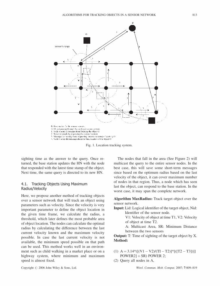
The Figure 1 describes the basic functions of the
location tracking system. The base station queries the
home node (HN) for tracking the latest location of
the object. Later the HN, queries its Nbrs for its latest
position. The above process ends when the network
finds the latest location of the object. The node will
report to the base station and in turn, the base station
updates the home node against the Lid.
Algorithm Track Object: Find a home node of the
object.
Input: Lid: Logical identifier of the target object
HN (Lid): Home Node of the Lid.
Output: X: Identifier of a sensor, which saw the target
object
Method:
(1) Query all nodes in Nbrs of HN (Lid)
(2) If no nodes in Nbrs of HN(Lid) have seen Lid
later, send(Nid, T(Nid, Lid)) to the base station.
(3) Else each node sends its T(Nid, Lid)) if it is
greater than T(HN, Lid) else drop the message.
(4) Query the node with the latest T(Nid,Lid) to do
TrackObject;
(5) Return(X);
The 1st phase of the algorithm returns the identifier
of the node with the most recent sighting time and is
assigned as the home node of the object. The base
station will contact the HN to continue to track
objects. The elected node, HN, then starts the process
of following the trail of the target object. If the target
object moved out of range of the sensor, it must have
gone into the range of one of its neighbors. By finding
the particular neighbor, the elected node who saw the
target object last can determine the next step in the
trail of the target object. Such a neighbor is then
elected as the home node to follow the target object.
The trail stops when a node on the trail had seen the
target object after entire neighboring area is searched.
The trail stop implies that either the target object is still
in the range of this existing node, or the elected node is
an edge node and the target object has left the grid of
sensors. In either case, we found the most recent
sighting of the target object. Such a node then responds
back to the base station giving its identifier and the
812 A. RAPAKA AND S. MADRIA
Copyright # 2006 John Wiley & Sons, Ltd. Wirel. Commun. Mob. Comput. 2007; 7:809–819
sighting time as the answer to the query. Once re-
turned, the base station updates the HN with the node
that responded with the latest time stamp of the object.
Next time, the same query is directed to its new HN.
4.1. Tracking Objects Using MaximumRadius/Velocity
Here, we propose another method of tracking objects
over a sensor network that will track an object using
parameters such as velocity. Since the velocity is very
important parameter to define the object location in
the given time frame, we calculate the radius, a
threshold, which later defines the most probable area
of object location. The nodes can calculate the optimal
radius by calculating the difference between the last
current velocity known and the maximum velocity
possible. In case the last current velocity is not
available, the minimum speed possible on that path
can be used. This method works well in an environ-
ment such as child walking in a market place or on a
highway system, where minimum and maximum
speed is almost fixed.
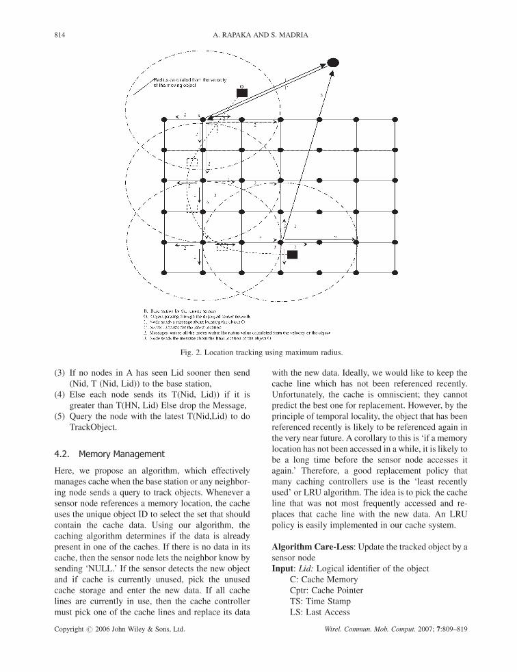
The nodes that fall in the area (See Figure 2) will
multicast the query to the entire sensor nodes. In the
best case, this will save some short-term messages
since based on the optimum radius based on the last
velocity of the object, it can cover maximum number
of nodes in that region. Thus, a node which has seen
last the object, can respond to the base station. In the
worst case, it may span the complete network.
Algorithm MaxRadius: Track target object over the
sensor network.
Input: Lid: Logical identifier of the target object, Nid:
Identifier of the sensor node.
V1: Velocity of object at time T1, V2: Velocity
of object at time T2.
A: Multicast Area, SR: Minimum Distance
between the two sensors
Output: T: Time of sighting of the target object by X.
Method:
(1) A¼ 3.14*([(V1�V2)/(TI�T2)]*[([T2�T3])]]
POWER2]þ SR) POWER 2;
(2) Query all nodes in A,
Fig. 1. Location tracking system.
ALGORITHMS FOR TRACKING OBJECTS IN A SENSOR NETWORK 813
Copyright # 2006 John Wiley & Sons, Ltd. Wirel. Commun. Mob. Comput. 2007; 7:809–819
(3) If no nodes in A has seen Lid sooner then send
(Nid, T (Nid, Lid)) to the base station,
(4) Else each node sends its T(Nid, Lid)) if it is
greater than T(HN, Lid) Else drop the Message,
(5) Query the node with the latest T(Nid,Lid) to do
TrackObject.
4.2. Memory Management
Here, we propose an algorithm, which effectively
manages cache when the base station or any neighbor-
ing node sends a query to track objects. Whenever a
sensor node references a memory location, the cache
uses the unique object ID to select the set that should
contain the cache data. Using our algorithm, the
caching algorithm determines if the data is already
present in one of the caches. If there is no data in its
cache, then the sensor node lets the neighbor know by
sending ‘NULL.’ If the sensor detects the new object
and if cache is currently unused, pick the unused
cache storage and enter the new data. If all cache
lines are currently in use, then the cache controller
must pick one of the cache lines and replace its data
with the new data. Ideally, we would like to keep the
cache line which has not been referenced recently.
Unfortunately, the cache is omniscient; they cannot
predict the best one for replacement. However, by the
principle of temporal locality, the object that has been
referenced recently is likely to be referenced again in
the very near future. A corollary to this is ‘if a memory
location has not been accessed in a while, it is likely to
be a long time before the sensor node accesses it
again.’ Therefore, a good replacement policy that
many caching controllers use is the ‘least recently
used’ or LRU algorithm. The idea is to pick the cache
line that was not most frequently accessed and re-
places that cache line with the new data. An LRU
policy is easily implemented in our cache system.
Algorithm Care-Less: Update the tracked object by a
sensor node
Input: Lid: Logical identifier of the object
C: Cache Memory
Cptr: Cache Pointer
TS: Time Stamp
LS: Last Access
Fig. 2. Location tracking using maximum radius.
814 A. RAPAKA AND S. MADRIA
Copyright # 2006 John Wiley & Sons, Ltd. Wirel. Commun. Mob. Comput. 2007; 7:809–819
Output: C Update the cache line
Method:
(1) While (C is Null)
� Sensor node searches the location of the Sear-
ch(Lid)
(2) If (search(Lid)¼ ¼Null)
� *(Cptr)¼ Id;
� Enter the TS of LS¼TS against Cptr;
� Cptrþ þ ;
Else
� Calculate the least used cache line on LS using
LRU;
� Enter the Id against the cache line;
� Enter the TS of LS¼TS;
4.3. Randomized Algorithm forShort Range Communication
Given the highly probable interference, sampling over
a time window per transmitter in the sensor node
would be a good idea to estimate the correct location
and also resolves the ambiguity in time stamp. For
example, when the object is equidistance from the
neighboring sensor nodes, there is always a high
probability that neighboring nodes duplicate the
same timestamp and thus, leads to inefficient memory
management. Also, issues like carrier-sense-style
channel to avoid collisions need intensive recourses
and heavy computing, which the sensor nodes cannot
sustain.
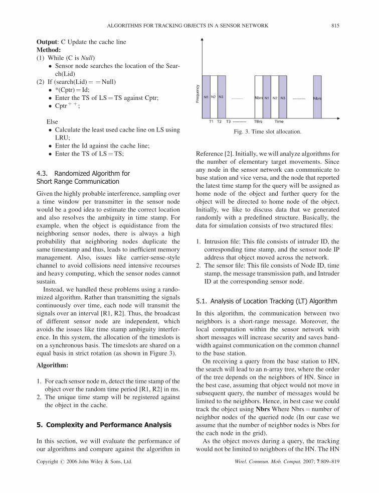
Instead, we handled these problems using a rando-
mized algorithm. Rather than transmitting the signals
continuously over time, each node will transmit the
signals over an interval [R1, R2]. Thus, the broadcast
of different sensor node are independent, which
avoids the issues like time stamp ambiguity interfer-
ence. In this system, the allocation of the timeslots is
on a synchronous basis. The timeslots are shared on a
equal basis in strict rotation (as shown in Figure 3).
Algorithm:
1. For each sensor node m, detect the time stamp of the
object over the random time period [R1, R2] in ms.
2. The unique time stamp will be registered against
the object in the cache.
5. Complexity and Performance Analysis
In this section, we will evaluate the performance of
our algorithms and compare against the algorithm in
Reference [2]. Initially, we will analyze algorithms for
the number of elementary target movements. Since
any node in the sensor network can communicate to
base station and vice versa, and the node that reported
the latest time stamp for the query will be assigned as
home node of the object and further query for the
object will be directed to home node of the object.
Initially, we like to discuss data that we generated
randomly with a predefined structure. Basically, the
data for simulation consists of two structured files:
1. Intrusion file: This file consists of intruder ID, the
corresponding time stamp, and the sensor node IP
address that object moved across the network.
2. The sensor file: This file consists of Node ID, time
stamp, the message transmission path, and Intruder
ID at the corresponding sensor node.
5.1. Analysis of Location Tracking (LT) Algorithm
In this algorithm, the communication between two
neighbors is a short-range message. Moreover, the
local computation within the sensor network with
short messages will increase security and saves band-
width against communication on the common channel
to the base station.
On receiving a query from the base station to HN,
the search will lead to an n-array tree, where the order
of the tree depends on the neighbors of HN. Since in
the best case, assuming that object would not move in
subsequent query, the number of messages would be
limited to the neighbors. Hence, in best case we could
track the object using Nbrs Where Nbrs¼ number of
neighbor nodes of the queried node (In our case we
assume that the number of neighbor nodes is Nbrs for
the each node in the grid).
As the object moves during a query, the tracking
would not be limited to neighbors of the HN. The HN
Fig. 3. Time slot allocation.
ALGORITHMS FOR TRACKING OBJECTS IN A SENSOR NETWORK 815
Copyright # 2006 John Wiley & Sons, Ltd. Wirel. Commun. Mob. Comput. 2007; 7:809–819
starts the process of following the trail for the queried
target object. Once the target object moved out of
range of a sensor node, it must be in the range of one
of its nbr node in the grid. By finding the particular
neighbor who spotted the target object last, will
determine the next step in the trail of the target
object. The trail stops when either the target object
is still in the range of this existing node, or the
elected node is an edge node and the target object
has left the grid of sensors. Such a node then
responds back to the base station giving its identifier
and sighting time as the answer to the query. The
base station will update the HN corresponding to
the object and the next query for the object would be
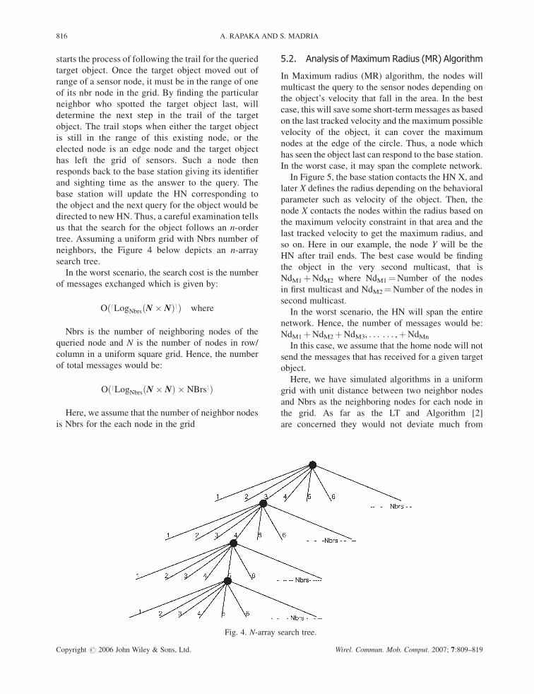
directed to new HN. Thus, a careful examination tells
us that the search for the object follows an n-order
tree. Assuming a uniform grid with Nbrs number of
neighbors, the Figure 4 below depicts an n-array
search tree.
In the worst scenario, the search cost is the number
of messages exchanged which is given by:
O dLogNbrsðN � NÞð eÞ where
Nbrs is the number of neighboring nodes of the
queried node and N is the number of nodes in row/
column in a uniform square grid. Hence, the number
of total messages would be:
O dLogNbrsðN � NÞ � NBrsð eÞ
Here, we assume that the number of neighbor nodes
is Nbrs for the each node in the grid
5.2. Analysis of Maximum Radius (MR) Algorithm
In Maximum radius (MR) algorithm, the nodes will
multicast the query to the sensor nodes depending on
the object’s velocity that fall in the area. In the best
case, this will save some short-term messages as based
on the last tracked velocity and the maximum possible
velocity of the object, it can cover the maximum
nodes at the edge of the circle. Thus, a node which
has seen the object last can respond to the base station.
In the worst case, it may span the complete network.
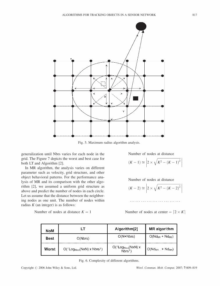
In Figure 5, the base station contacts the HN X, and
later X defines the radius depending on the behavioral
parameter such as velocity of the object. Then, the
node X contacts the nodes within the radius based on
the maximum velocity constraint in that area and the
last tracked velocity to get the maximum radius, and
so on. Here in our example, the node Y will be the
HN after trail ends. The best case would be finding
the object in the very second multicast, that is
NdM1þNdM2 where NdM1¼Number of the nodes
in first multicast and NdM2¼Number of the nodes in
second multicast.
In the worst scenario, the HN will span the entire
network. Hence, the number of messages would be:
NdM1þNdM2þNdM3, . . . . . . ,þNdMn
In this case, we assume that the home node will not
send the messages that has received for a given target
object.
Here, we have simulated algorithms in a uniform
grid with unit distance between two neighbor nodes
and Nbrs as the neighboring nodes for each node in
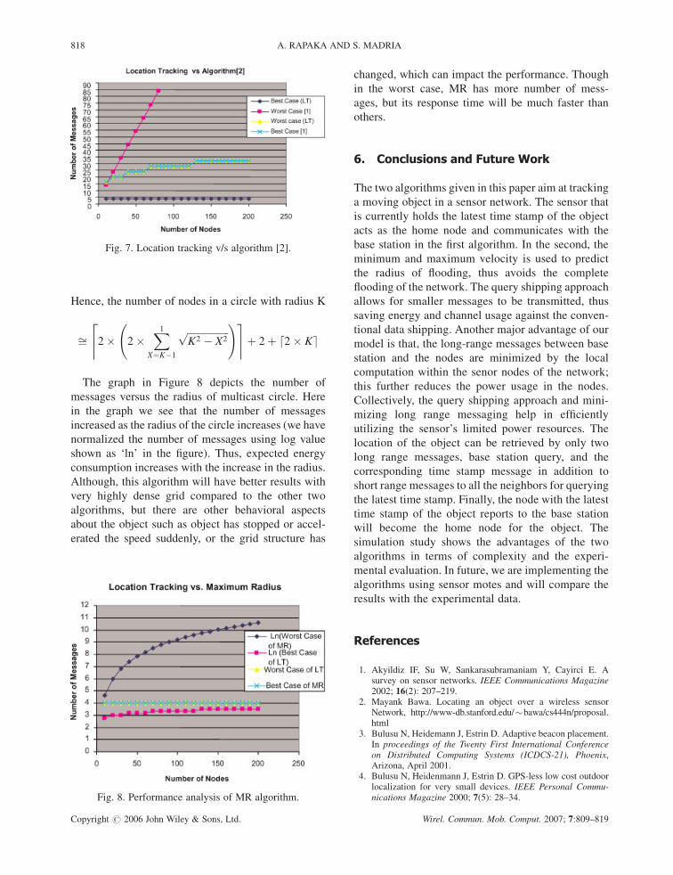
the grid. As far as the LT and Algorithm [2]
are concerned they would not deviate much from
Fig. 4. N-array search tree.
816 A. RAPAKA AND S. MADRIA
Copyright # 2006 John Wiley & Sons, Ltd. Wirel. Commun. Mob. Comput. 2007; 7:809–819
generalization until Nbrs varies for each node in the
grid. The Figure 7 depicts the worst and best case for
both LT and Algorithm [2].
In MR algorithm, the analysis varies on different
parameter such as velocity, grid structure, and other
object behavioral patterns. For the performance ana-
lysis of MR and its comparison with the other algo-
rithm [2], we assumed a uniform grid structure as
above and predict the number of nodes in each circle.
Let us assume that the distance between the neighbor-
ing nodes as one unit. The number of nodes within
radius K (an integer) is as follows:
Number of nodes at distance K ¼ 1
Number of nodes at distance
ðK � 1Þ ffi 2�ffiffiffiffiffiffiffiffiffiffiffiffiffiffiffiffiffiffiffiffiffiffiffiffiffiffiffiffiffiK2 � ðK � 1Þ2
q��������
Number of nodes at distance
ðK � 2Þ ffi 2�ffiffiffiffiffiffiffiffiffiffiffiffiffiffiffiffiffiffiffiffiffiffiffiffiffiffiffiffiffiK2 � ðK � 2Þ2
q��������
. . . . . . . . . . . . . . . . . . . . . . . . . . .
Number of nodes at center ¼ 2� Kd e
Fig. 5. Maximum radius algorithm analysis.
Fig. 6. Complexity of different algorithms.
ALGORITHMS FOR TRACKING OBJECTS IN A SENSOR NETWORK 817
Copyright # 2006 John Wiley & Sons, Ltd. Wirel. Commun. Mob. Comput. 2007; 7:809–819
Hence, the number of nodes in a circle with radius K
ffi 2� 2�X1
X¼K�1
ffiffiffiffiffiffiffiffiffiffiffiffiffiffiffiffiffiK2 � X2
p !& ’þ 2þ 2� Kd e
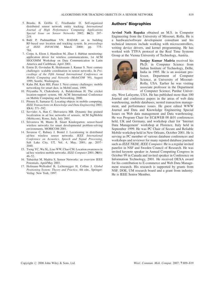
The graph in Figure 8 depicts the number of
messages versus the radius of multicast circle. Here
in the graph we see that the number of messages
increased as the radius of the circle increases (we have
normalized the number of messages using log value
shown as ‘ln’ in the figure). Thus, expected energy
consumption increases with the increase in the radius.
Although, this algorithm will have better results with
very highly dense grid compared to the other two
algorithms, but there are other behavioral aspects
about the object such as object has stopped or accel-
erated the speed suddenly, or the grid structure has
changed, which can impact the performance. Though
in the worst case, MR has more number of mess-
ages, but its response time will be much faster than
others.
6. Conclusions and Future Work
The two algorithms given in this paper aim at tracking
a moving object in a sensor network. The sensor that
is currently holds the latest time stamp of the object
acts as the home node and communicates with the
base station in the first algorithm. In the second, the
minimum and maximum velocity is used to predict
the radius of flooding, thus avoids the complete
flooding of the network. The query shipping approach
allows for smaller messages to be transmitted, thus
saving energy and channel usage against the conven-
tional data shipping. Another major advantage of our
model is that, the long-range messages between base
station and the nodes are minimized by the local
computation within the senor nodes of the network;
this further reduces the power usage in the nodes.
Collectively, the query shipping approach and mini-
mizing long range messaging help in efficiently
utilizing the sensor’s limited power resources. The
location of the object can be retrieved by only two
long range messages, base station query, and the
corresponding time stamp message in addition to
short range messages to all the neighbors for querying
the latest time stamp. Finally, the node with the latest
time stamp of the object reports to the base station
will become the home node for the object. The
simulation study shows the advantages of the two
algorithms in terms of complexity and the experi-
mental evaluation. In future, we are implementing the
algorithms using sensor motes and will compare the
results with the experimental data.
References
1. Akyildiz IF, Su W, Sankarasubramaniam Y, Cayirci E. Asurvey on sensor networks. IEEE Communications Magazine2002; 16(2): 207–219.
2. Mayank Bawa. Locating an object over a wireless sensorNetwork, http://www-db.stanford.edu/�bawa/cs444n/proposal.html
3. Bulusu N, Heidemann J, Estrin D. Adaptive beacon placement.In proceedings of the Twenty First International Conferenceon Distributed Computing Systems (ICDCS-21), Phoenix,Arizona, April 2001.
4. Bulusu N, Heidenmann J, Estrin D. GPS-less low cost outdoorlocalization for very small devices. IEEE Personal Commu-nications Magazine 2000; 7(5): 28–34.
Fig. 7. Location tracking v/s algorithm [2].
Fig. 8. Performance analysis of MR algorithm.
818 A. RAPAKA AND S. MADRIA
Copyright # 2006 John Wiley & Sons, Ltd. Wirel. Commun. Mob. Comput. 2007; 7:809–819
5. Brooks B, Griffin C, Friedlander D. Self-organizeddistributed sensor network entity tracking. InternationalJournal of High Performance Computing ApplicationsSpecial Issue on Sensor Networks 2002; 16(2): 207–219.
6. Bahl P, Padmanbhan VN. RADAR: an in buildingRF-based user location and tracking system. In proceedingsof IEEE INFOCOM, March 2000; pp. 775–784.
7. Cerpa A, Elson J, Hamilton M, Zhao J. Habitat monitoring:application driver for wireless communications, 1st ACMSIGCOMM Workshop on Data Communication in LatinAmerica and Caribbean, April 2001.
8. Estrin D, Govindan R, Heidemann J, Kumar S. Next centurychallenges: scalable coordination in sensor networks. In Pro-ceedings of the Fifth Annual International Conference onMobile Computing and Networks (MobiCOM ’99), August1999, Seattle, Washington.
9. Kahn JM, Katz RH, Pister J. Next century challenges: mobilenetworking for smart dust, in MobiComm, 1999.
10. Priyantha N, Chakraborty A, Balakrishnan H. The cricketlocation-support system, 6th ACM International Conferenceon Mobile Computing and Networking, 2000.
11. Pitoura E, Samaras G. Locating objects in mobile computing.IEEE Transactions on Knowledge and Data Engineering 2001;13(4): 571–592.
12. Savvides A, Han C, Shrivastava MB. Dynamic fine grainedlocalization in ad hoc networks of sensors, ACM SigMobile(Mobicom), Rome, Italy, July 2001.
13. Srivastava M, Muntz R. Smart Kindergarten: sensor-basedwireless networks for smart developmental problem-solvingenvironments, MOBICOM 2001.
14. Savarese C, Rabaey J, Beutel J. Locationing in distributedad-hoc wireless sensor networks. IEEE InternationalConference on Acoustics, Speech and Signal Processing,Salt Lake City, UT, Vol. 4, May, 2001; pp. 2037–2040.
15. Tseng YC,Wu SL, LiaoWW, Chao CM. Location awareness inad hoc wireless mobile networks. IEEE Computer 2001; 34(6):46–52.
16. Tubaishat M, Madria S, Sensor Networks: an overview IEEEPotentials, April/May 2003.
17. Hofmann-Wellenhof B, Lichtenegger H, Collins J. GlobalPositioning System: Theory and Practice, 4th edn., Springer-Verlag: New York, 1997.
Authors’ Biographies
Arvind Nath Rapaka obtained an M.S. in ComputerEngineering from the University of Missouri, Rolla. He isa hardware/software development consultant and histechnical interests include working with microcontrollers,writing device drivers, and kernel programming. He hasworked with TTP/A protocol at the Real Time SystemsGroup at the Vienna University of Technology, Austria.
Sanjay Kumar Madria received hisPh.D. in Computer Science fromIndian Institute of Technology, Delhi,India in 1995. He is an assistant pro-fessor, Department of ComputerScience, at University of Missouri-Rolla, USA. Earlier he was visitingassociate professor in the Departmentof Computer Science, Purdue Univer-
sity, West Lafayette, USA. He has published more than 100Journal and conference papers in the areas of web datawarehousing, mobile databases, nested transaction manage-ment, and performance issues. He guest edited WWWJournal and Data and Knowledge Engineering SpecialIssues on Web data management and Data warehousing.He was Program Chair for EC&WEB 00 &01 conferencesheld, UK and Germany, and workshop chair for ‘InternetData Management’ workshop at Florence, Italy held inSeptember 1999. He was PC Chair of Secure and ReliableMobile workshop held in New Orleans, October 2001. He isserving as PC member of various database conferences andworkshops and reviewer for many reputed database journalssuch as IEEE TKDE, IEEE Computer. He is a regular invitedpanelist in NSF and Sweden Council of Research. He wasinvited keynote speaker in Annual Computing Congress inOctober 99 in Canada and invited speaker in Conference onInformation Technology, 2001. He received DEXA awardfor his contribution to E-commerce and Web Data Manage-ment research. His research is supported by grants fromNSF, DOE, UM research board and a grant from industry.He is IEEE Senior Member.
ALGORITHMS FOR TRACKING OBJECTS IN A SENSOR NETWORK 819
Copyright # 2006 John Wiley & Sons, Ltd. Wirel. Commun. Mob. Comput. 2007; 7:809–819