Embed Size (px)
Citation preview

Two-Dimensional Viewing
Chapter 6

The Viewing Pipeline• Window
• A world-coordinate area selected for display.
defines what is to be viewed
• Viewport
• An area on a display device to which a window is mapped.
defines where it is to be displayed
• Viewing transformation
• The mapping of a part of a world-coordinate scene to device coordinates.
• A window could be a rectangle to have any orientation.

Two-Dimensional Viewing

The Viewing Pipeline

The Viewing Pipeline

Viewing Effects• Zooming effects
• Successively mapping different-sized windows on a fixed-sized viewports.
• Panning effects • Moving a fixed-sized window across the various
objects in a scene.
• Device independent • Viewports are typically defined within the unit s
quare (normalized coordinates)

Viewing Coordinate Reference Frame
• The reference frame for specifying the world-coordinate window.
• Viewing-coordinate origin: P0 = (x0, y0)
• View up vector V: Define the viewing yv direction

Window-to-Viewport Coordinate Transformation

Window-to-Viewport Coordinate Transformation
minmax
min
minmax
min
xwxw
xwxw
xvxv
xvxv
minmax
min
minmax
min
ywyw
ywyw
yvyv
yvyv
sxxwxwxvxv )( minmin syywywyvyv )( minmin
minmax
minmax
ywyw
yvyvsy
minmax
minmax
xwxw
xvxvsx

Workstation transformtion

Clipping Operations
• Clipping • Identify those portions of a picture that are either
inside or outside of a specified region of space.
• Clip window • The region against which an object is to be clipped.
• The shape of clip window
• Applications of clipping
• World-coordinate clipping

Clipping Operations• Viewport clipping
• It can reduce calculations by allowing concatenation of viewing and geometric transformation matrices.
• Types of clipping • Point clipping • Line clipping • Area (Polygon) clipping • Curve clipping • Text clipping
• Point clipping (Rectangular clip window)

Line Clipping• Possible relationships between line positions
and a standard rectangular clipping region
Before clipping after clipping

Line Clipping• Possible relationships
– Completely inside the clipping window – Completely outside the window – Partially inside the window
• Parametric representation of a line x = x1 + u(x2 - x1)
y = y1 + u(y2 - y1)
• The value of u for an intersection with a rectangle boundary edge – Outside the range 0 to 1 – Within the range from 0 to 1

Cohen-Sutherland Line Clipping• Region code
– A four-digit binary code assigned to every line endpoint in a picture.
– Numbering the bit positions in the region code as 1 through 4
from right to left.

Cohen-Sutherland Line Clipping
• Bit values in the region code • Determined by comparing endpoint coordinates to
the clip boundaries • A value of 1 in any bit position: The point is in that relative
position.
• Determined by the following steps: • Calculate differences between endpoint coordinates
and clipping boundaries.
• Use the resultant sign bit of each difference calculation to set the corresponding bit value.

Cohen-Sutherland Line Clipping
• The possible relationships: • Completely contained within the window
• 0000 for both endpoints.
• Completely outside the window • Logical and the region codes of both endpoints, its result is
not 0000.
• Partially

Liang-Barsky Line Clipping
• Rewrite the line parametric equation as follows:
• Point-clipping conditions:
• Each of these four inequalities can be expressed as:
xuxx 1
yuyy 1 10 u
max1min xwxuxxw
max1min ywyuyyw
kk qup 4,3,2,1k
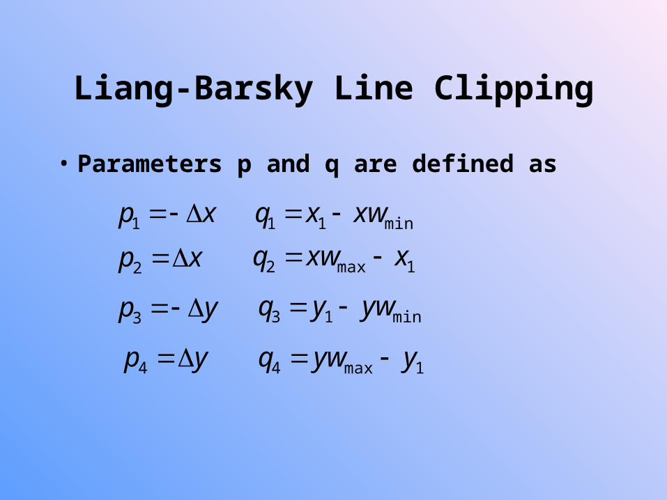
Liang-Barsky Line Clipping
• Parameters p and q are defined as
xp 1
xp 2
yp 3
yp 4
min11 xwxq
1max2 xxwq
1max4 yywq
min13 ywyq

Liang-Barsky Line Clipping
• pk = 0, parallel to one of the clipping boundary
• qk < 0, outside the boundary
• qk >= 0, inside the parallel clipping boundary
• pk < 0, the line proceeds from outside to the inside
• pk > 0, the line proceeds from inside to outside

Liang-Barsky Line Clipping

Liang-Barsky Line Clipping
• Parameters u1 and u2 that define that part of the line lies within the clip rectangle
• The value of u1 : From outside to inside (pk < 0)
• The value of u2 : From inside to outside (pk > 0)
• If u1 > u2, the line is completely outside the clip window.
),0max( '1 sru k
k
kk p
qr
),1min( '2 sru k
k
kk p
qr

Liang-Barsky Line Clipping

Nicholl-Lee-Nicholl Line Clipping• Compared to C-S and L-B algorithms
• NLN algorithm performs fewer comparisons and divisions.
• NLN can only be applied to 2D clipping. • The NLN algorithm
• Clip a line with endpoints P1 and P2
• First determine the position of P1 for the nine possible regions. • Only three regions need be considered • The other regions using a symmetry
transformation
• Next determine the position of P2 relative to P1.

Nicholl-Lee-Nicholl Line Clipping

Nicholl-Lee-Nicholl Line Clipping

Nicholl-Lee-Nicholl Line Clipping

Nicholl-Lee-Nicholl Line Clipping
• To determine the region in which P2 is located – Compare the slope of the line to the slopes of the boundaries of
the clip region.
– Example: P1 is left of the clipping rectangle, P2 is in region LT.
Nonrectangular Clip Windows• Algorithms based on parametric line equations
can be extended • Liang-Barsky method • Modify the algorithm to include the parametric equa
tions for the boundaries of the clip region
• Concave polygon-clipping regions • Split into a set of convex polygons • Apply parametric clipping procedures
• Circle or other curved-boundary clipping regions • Lines can be clipped against the bounding rectangle

Splitting Concave Polygons• Identify a concave polygon
• Calculating the cross product of successive edge vectors.
• If the z component of some cross product is positive while others have a negative, it is concave.

Splitting Concave Polygons• Vector method
– Calculate the edge-vector cross product in a counterclockwise order.
– If any z component turns out to be negative • The polygon is concave.
• Split it along the line of the first edge vector in the cross-product pair.

Splitting Concave Polygons
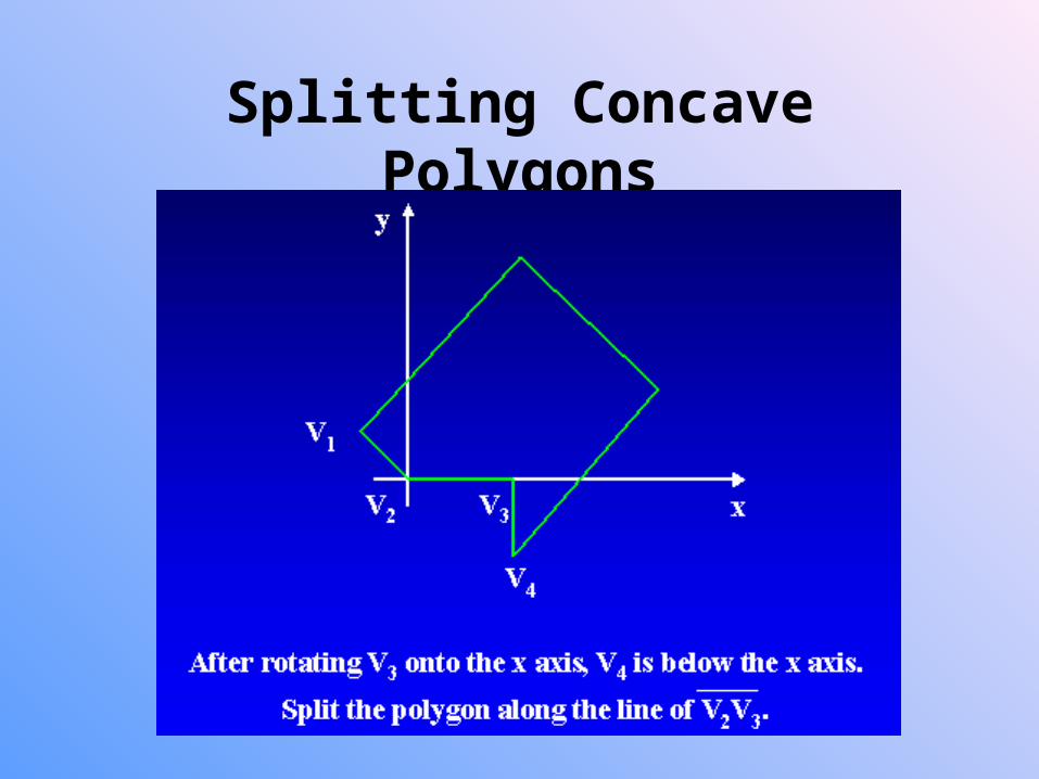
• Rotational method • Proceeding counterclockwise around the polygon ed
ges.
• Translate each polygon vertex Vk to the coordinate origin.
• Rotate in a clockwise direction so that the next vertex Vk+1 is on the x axis.
• If the next vertex, Vk+2, is below the x axis, the polygon is concave.
• Split the polygon along the x axis.
Splitting Concave Polygons

Polygon Clipping

Sutherland-Hodgeman Polygon Clipping
• Processing the polygon boundary as a whole against each window edge
• Processing all polygon vertices against each clip rectangle boundary in turn

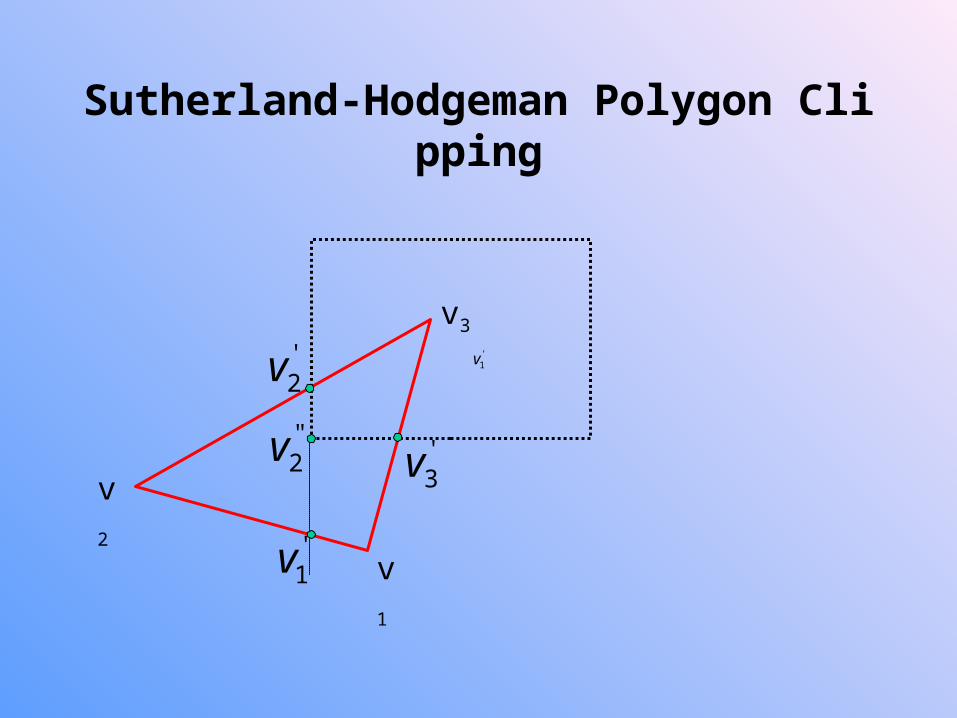
Sutherland-Hodgeman Polygon Clipping
• Pass each pair of adjacent polygon vertices to a window boundary clipper
• There are four cases:

Sutherland-Hodgeman Polygon Clipping
• Intermediate output vertex list • Once all vertices have been processed for one clip
window boundary, it is generated.
• The output list of vertices is clipped against the next window boundary.
• It can be eliminated by a pipeline of clipping routine.
• Convex polygons are correctly clipped.
• If the clipped polygon is concave • Split the concave polygon
Sutherland-Hodgeman Polygon Clipping
v1
v2
v3'1v
'1v
'2v
''2v '
3v

Weiler-Atherton Polygon Clipping
• Developed as a method for identifying visible surfaces • It can be applied with arbitrary polygon-clipping
region. • Not always proceeding around polygon edges • Sometimes follows the window boundaries
• For clockwise processing of polygon vertices • For an outside-to-inside pair of vertices, follow the
polygon boundary. • For an inside-to-outside pair of vertices, follow the
window boundary in clockwise direction.

Weiler-Atherton Polygon Clipping

Other Clipping
• Curve clipping • Use bounding rectangle to test for overlap
with a rectangular clip window.
• Text clipping • All-or-none string-clipping
• All-or-none character-clipping
• Clip the components of individual characters

Exterior Clipping• Save the outside region
• Applications • Multiple window systems
• The design of page layouts in advertising or publishing
• Adding labels or design patterns to a picture
• Procedures for clipping objects to the interior of concave polygon windows
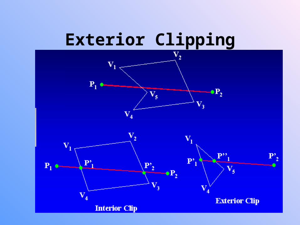
Exterior Clipping