Embed Size (px)
Citation preview
Journal of Electronic Imaging 10(3), 661–668 (July 2001).
Downl
Two-dimensional control systems: Learning fromimplementations
Stephen Richard DuncanDepartment of Engineering Science
Oxford UniversityOxford OX1 3PJUnited Kingdom
E-mail: [email protected]
-
at i
t o
mete
ands a
hedoesm-putuceup-
thep-ssan
cangftenn-
tl-may
athe
ingts arear-
atedthen-
m ay of
heif-ng
1; a
Abstract. The design of sensing and control systems for two-dimensional industrial processes such as paper making, plastic filmextrusion and metal rolling, has drawn extensively upon conceptsfrom two-dimensional signal processing and image processing. Theperformance of two-dimensional control systems is discussed interms of spatial and dynamic bandwidths and is illustrated by ex-amples from the control of cross-directional variations on a plasticfilm extrusion line. By relating these bandwidths to the specificationof the required quality of the finished film and typical disturbancesthat enter the process, specifications are developed for the design ofthe actuators, the sensing system and the control algorithm. It isshown that the current generation of control systems is not suitablefor controlling variations over small areas of sheet, but a systemwhich regulates over much smaller areas could be developed usingrecent developments in sensors and two-dimensional control algo-rithms. © 2001 SPIE and IS&T. [DOI: 10.1117/1.1379770]
1 Introduction
The control of two-dimensional~2D! systems can be considered as a special case ofdistributed parametercontrol.In distributed parameter control, the aim is to regulateparameter represented by a continuous function thaevolving in time. Compare this to the control oflumpedparametersystems, where a single discrete measuremena set of discrete measurements~multivariable system! arecontrolled.
Examples of 2D processes used in industry include:
• paper making;
• metal rolling;
• extrusion of plastic film;
• coating and converting;
• galvanizing of metal sheet;
• printing; and
• nonwoven materials.
In each of these processes, a continuous sheet is foror coated. The 2D control system is designed to regula
Paper IP-10 received Jan. 8, 2001; revised manuscript received Mar. 12, 200cepted for publication Mar. 13, 2001.1017-9909/2001/$15.00 © 2001 SPIE and IS&T.
oaded From: http://electronicimaging.spiedigitallibrary.org/ on 08/23/2013 T
s
r
da
specific property~or sometimes properties! of the sheet andthe aim is to reduce variations in both across the sheetalong its length. As a result, the design of a controller itwo-dimensional control problem.
One of the primary aims of the controller is to reduce tamount of material that has to be scrapped because itnot meet the specification on quality. This leads to iproved usage of raw materials and an improved throughand return on capital. The control system can also redthe time to settle a process following a startup or a disrtion.
For the industrial processes listed above, the aim ofcontrol system is to regulate variations of a specific proerty of the sheet. In this paper, the control of film thicknevariations on a plastic film extrusion line will be used asexample of a two-dimensional control problem. Ifx is usedto denote the cross-directional~CD! coordinate andt todenote the machine-directional~MD! coordinate, then thethickness variation at a particular point in the processbe denoted byP(x,t). Because the controller is regulatinvariations across the sheet as they evolve in time, it is oreferred to as cross-directional control. Typically, the cotroller will be required to regulateP(x,t) to some constanreference value,Pr , at all points throughout the sheet, athough, in some special circumstances, the referencedepend upon the cross-directional position,Pr(x). For sim-plicity, it will be assumed that the reference profile isconstant value, but the ideas can be readily extended tocase where the reference depends upon CD position.
The variations are measured using either a scanngauge or an array of fixed sensors. These measuremenused to adjust the set points of an array of actuatorsranged in a line across the sheet and are usually situupstream of the gauge, typically, close to the start ofprocess@a notable exception is the control of residual tesion in metal rolling where the actuator~s! can be posi-tioned after the sensor#. In the control of variations in filmthickness, the thickness measurements obtained froscanning gauge are used to adjust the settings of an arrascrews that bend the lip on the slit die, regulating tamount of molten polymer flowing through the die at dferent positions in the cross direction. Although bendi
c-
Journal of Electronic Imaging / July 2001 / Vol. 10(3) / 661
erms of Use: http://spiedl.org/terms
m-nahathefilm
is
ete-e
ot
rtyee
ntranon
lis
istom
msa
rmua
congu-
ouneerfodedyon
msim
sinossia-re-1
stice’rueemts o
or isage
,In-aria-enes
an-thetingetheof
sure-nirtu-d-to
gperthed tos in-
s. Asuponore
s-is
Athetua-
atedite
Duncan
Downl
the lip redistributes polymer in the cross direction, in comon with most actuators that are used in cross-directiocontrol systems, changing the settings of the screwsonly a small effect on the mean basis weight acrosssheet. For this reason, it is convenient to decomposethickness variations into1
P~x,t !5P01PMD~ t !1PCD~x,t !, ~1!
where:
• P0 is the mean level of the sheet property;
• PMD(t) is the machine-directional variation, whichindependent of cross-directional position; and
• PCD(x,t) is the cross-directional variation in the sheproperty which depends upon both the machindirectional and cross-directional position within thsheet.
Since thePMD(t) component of the variation does ndepend upon cross-directional positionx, it can be consid-ered as a variation in the average value of the propewhere the average is taken across the width of the shBecause the actuators used in the cross-directional cosystem only have a limited ability to regulate this melevel, it is necessary to have a separate machine-directicontrol system to regulateP01PMD(t) to the requiredvalue of the web propertyPr . With a machine-directionacontroller in place, the cross-directional control systemused to regulatePCD(x,t) to zero over the sheet and in thpaper, the ability of a cross-directional control systemachieve this aim is investigated. The approach of decoposing the control problem into two separate subprobleis much simpler and straightforward to implement thanfull two-dimensional controller.
Some authors have decomposed the termPCD(x,t) fur-ther into the sum of a true CD variation,PCD(x), that de-pends upon CD position only, and a residual tePR(x,t).1,2 These authors claim that because the residcomponent is due to random disturbances, it cannot betrolled and most CD control systems concentrate on relating only PCD(x). However, any CD controller can regulate at least part of the residual component and the amof the residual variation that can be removed from the shdepends upon the response of the actuators and the pemance of the sensing system and control algorithm. Unthese circumstances,PCD(x) can be regarded as the steastate component of the overall cross-directional variatiPCD(x,t).
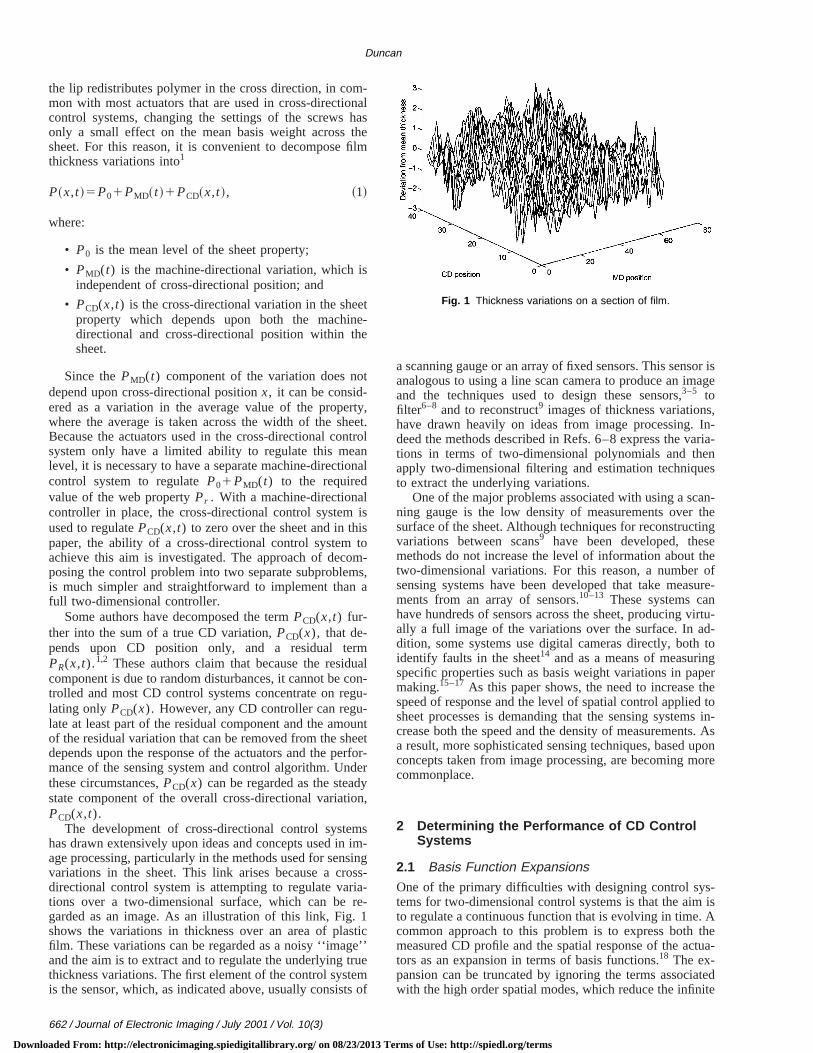
The development of cross-directional control systehas drawn extensively upon ideas and concepts used inage processing, particularly in the methods used for senvariations in the sheet. This link arises because a crdirectional control system is attempting to regulate vartions over a two-dimensional surface, which can begarded as an image. As an illustration of this link, Fig.shows the variations in thickness over an area of plafilm. These variations can be regarded as a noisy ‘‘imagand the aim is to extract and to regulate the underlying tthickness variations. The first element of the control systis the sensor, which, as indicated above, usually consis
662 / Journal of Electronic Imaging / July 2001 / Vol. 10(3)
oaded From: http://electronicimaging.spiedigitallibrary.org/ on 08/23/2013 T
ls
,t.ol
al
-,
l--
ttr-r
,
-g-
’
f
a scanning gauge or an array of fixed sensors. This sensanalogous to using a line scan camera to produce an imand the techniques used to design these sensors,3–5 tofilter6–8 and to reconstruct9 images of thickness variationshave drawn heavily on ideas from image processing.deed the methods described in Refs. 6–8 express the vtions in terms of two-dimensional polynomials and thapply two-dimensional filtering and estimation techniquto extract the underlying variations.
One of the major problems associated with using a scning gauge is the low density of measurements oversurface of the sheet. Although techniques for reconstrucvariations between scans9 have been developed, thesmethods do not increase the level of information abouttwo-dimensional variations. For this reason, a numbersensing systems have been developed that take meaments from an array of sensors.10–13 These systems cahave hundreds of sensors across the sheet, producing vally a full image of the variations over the surface. In adition, some systems use digital cameras directly, bothidentify faults in the sheet14 and as a means of measurinspecific properties such as basis weight variations in pamaking.15–17 As this paper shows, the need to increasespeed of response and the level of spatial control appliesheet processes is demanding that the sensing systemcrease both the speed and the density of measurementa result, more sophisticated sensing techniques, basedconcepts taken from image processing, are becoming mcommonplace.
2 Determining the Performance of CD ControlSystems
2.1 Basis Function Expansions
One of the primary difficulties with designing control sytems for two-dimensional control systems is that the aimto regulate a continuous function that is evolving in time.common approach to this problem is to express bothmeasured CD profile and the spatial response of the actors as an expansion in terms of basis functions.18 The ex-pansion can be truncated by ignoring the terms associwith the high order spatial modes, which reduce the infin
Fig. 1 Thickness variations on a section of film.
erms of Use: http://spiedl.org/terms
nitnd
bed
heth
onx-
ssof
o
nlya
s;
eche
Dvethe
tiasio
colleaced
elothaposiothe
osee tas
heromth
of
esto
d
. Ithisncegtherhw-s its,
thee-ia-
cestur-peci-betrolade.atial2
in
e
all aon-
ag-tur-by
m-both
there
Two-dimensional control systems
Downl
dimensional response of the continuous response to a fidimensional system, making it possible to design aimplement practical control systems.
Many two-dimensional control systems can be describy an underlying partial differential equation~PDE! and thenatural basis functions to use are the eigenfunctions of tspatial operator in the PDE. In practice, the response ofsystem is usually to be derived from online identificatiexperiments and it is unlikely that the PDE is known eactly. For this reason, the Galerkin approach19 is oftenused, where the spatial response of the system is exprein terms of arbitrary orthogonal functions. A numberdifferent basis functions have been used in the designCD control systems:
• square impulse functions. This is the most commoused form of basis function and can be regardedaveraging the CD variations over a number of zone20
• eigenfunctions of the Grammian matrix,21 which intheir discrete sampled form, become the singular vtors of the interaction matrix obtained by sampling tspatial responses of the actuators;4,22,23
• Fourier methods;4,5,24–27
• orthogonal polynomials;21,28,29
• the eigenvectors of the correlation matrix of the Cvariations.30 This approach uses the Karhunen–Loetechnique to determine the basis functions fromvariations inherent in the process;
• splines;31 and
• wavelets.32
Using basis, function expansions to express the spavariations has two further advantages. First, the expandecouples the system, so that each of the spatial modesbe considered separately. This means that the contrdesign reduces to determining suitable dynamics for espatial mode, although, in practice, it is usually assumthat each mode has the same dynamics, as described bSecond, by truncating the basis function expansion, sothe responses are restricted to only those spatial comnents that can be regulated by the actuators, the dimenof the system can be reduced, simplifying the design ofcontroller.5
An advantage of using Fourier methods to decompthe spatial response is that it allows the spatial responsbe expressed in terms of ‘‘time domain’’ concepts suchbandwidth. While the Fourier methods strictly require tspatial response to be periodic, the errors that result fthis assumption tend to be small and are outweighed byengineering insight that is gained from the approach.27,33
2.2 Quality Specifications and Disturbances
The starting point for any analysis of the performanceany control system is a definition of:
• what is the required level of control; and
• what are the typical disturbances entering the procthat need to be removed from the sheet in orderachieve the required quality specification?
For example, the desired performance can be expresse
oaded From: http://electronicimaging.spiedigitallibrary.org/ on 08/23/2013 T
e
ne
ed
f
s
-
lnanr
h
w.t-n
o
e
s
in
terms of the standard deviation~or variance! of the accept-able level of basis weight variation in the finished sheetis important to define the area of sheet over which tquality specification is measured as there is a big differebetween controlling thickness variations over a short lenof film compared to controlling the average deviation ova whole reel. It is also worth pointing out that, althougmost quality specifications are expressed in terms of alloable variance or standard deviation, in some applicationis better to attempt to minimize the range of variationwhich requires a different approach to the design ofcontroller.34–36 In this paper, control systems that are dsigned to minimize the variance of the basis weight vartions will be considered.
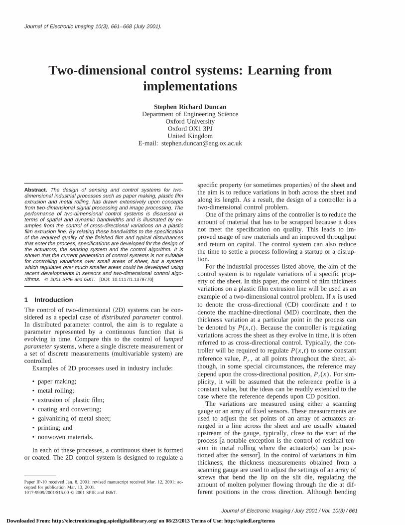
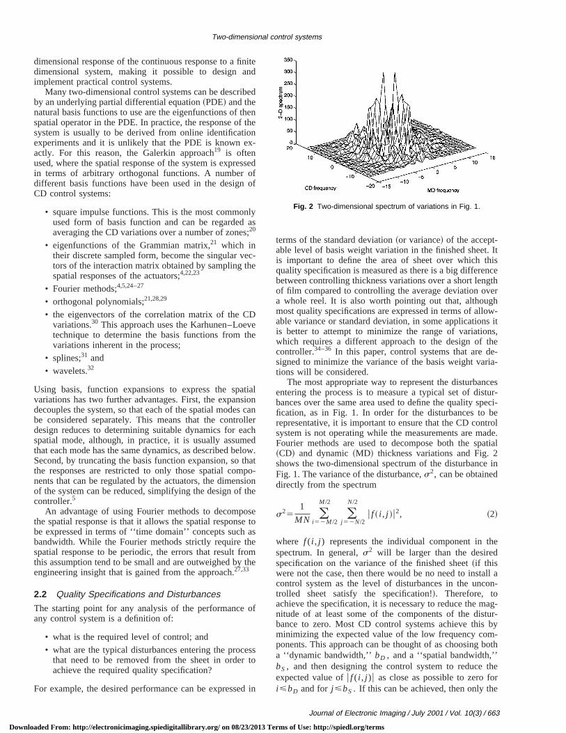
The most appropriate way to represent the disturbanentering the process is to measure a typical set of disbances over the same area used to define the quality sfication, as in Fig. 1. In order for the disturbances torepresentative, it is important to ensure that the CD consystem is not operating while the measurements are mFourier methods are used to decompose both the sp~CD! and dynamic~MD! thickness variations and Fig.shows the two-dimensional spectrum of the disturbanceFig. 1. The variance of the disturbance,s2, can be obtaineddirectly from the spectrum
s251
MN (i 52M /2
M /2
(j 52N/2
N/2
u f ~ i , j !u2, ~2!
where f ( i , j ) represents the individual component in thspectrum. In general,s2 will be larger than the desiredspecification on the variance of the finished sheet~if thiswere not the case, then there would be no need to instcontrol system as the level of disturbances in the unctrolled sheet satisfy the specification!!. Therefore, toachieve the specification, it is necessary to reduce the mnitude of at least some of the components of the disbance to zero. Most CD control systems achieve thisminimizing the expected value of the low frequency coponents. This approach can be thought of as choosinga ‘‘dynamic bandwidth,’’bD , and a ‘‘spatial bandwidth,’’bS , and then designing the control system to reduceexpected value ofu f ( i , j )u as close as possible to zero foi<bD and for j <bS . If this can be achieved, then only th
Fig. 2 Two-dimensional spectrum of variations in Fig. 1.
Journal of Electronic Imaging / July 2001 / Vol. 10(3) / 663
erms of Use: http://spiedl.org/terms
innc
oisabe
lityce
le-
tentiaendestssv-efdy
is
idth
edhenthe
nd-the
dis
ast,idth-, so
ofon-ho-e
ria-be
isthatx tohasn ofutve
ng’’nss
ofse aense
e of
der
Duncan
Downl
‘‘high frequency’’ components of the disturbance remainthe sheet, so that the expected variance of the disturbain the finished sheet is
1
MN (u i u.bD
(u j u.bS
u f ~ i , j !u2. ~3!
The two bandwidths,bD and bS , need to be chosen tensure that the variance of the uncontrolled variationsless than the allowed variance in the finished productdefined by the quality specification. This approach canused to determine suitable bandwidths from the quaspecification and the spectrum of the expected disturbanwhich in turn, determines the design of:
• the actuators;
• the sensing system; and
• the control algorithm.
2.3 Design of CD Actuators
Most of the CD control systems that are currently impmented are based upon the assumption~either explicitly orimplicitly ! that response of the actuator array can be writas the product of a dynamic component and the spa~CD! response of the array of actuators. This is equivalto assuming that the dynamics of each of the spatial moof the problem are the same, which is justified for mopractical systems because the dynamics of the procemoving the actuators~i.e., the motors or heated bolts moing the lip screws in the die! are much slower than thdecay of the bending modes of the lip.37 The response othe dynamic component of the actuators determines thenamic bandwidth,bD , while the spatial~CD! response de-termines the spatial bandwidth,bS .
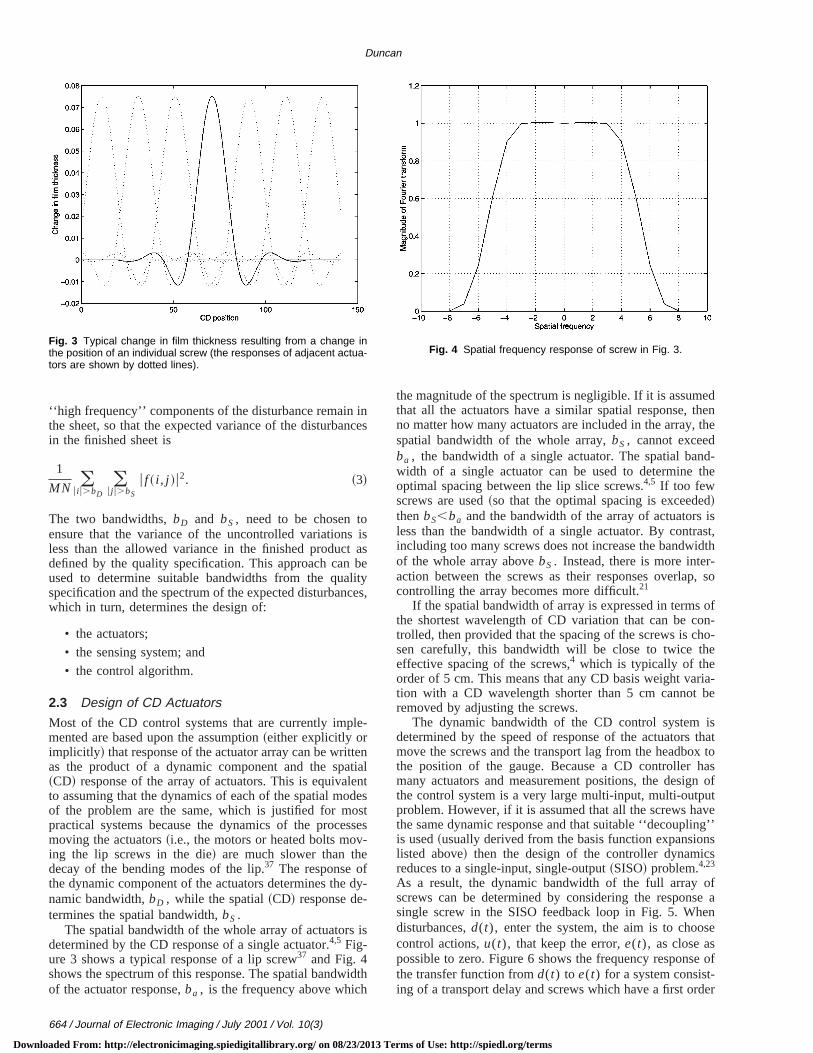
The spatial bandwidth of the whole array of actuatorsdetermined by the CD response of a single actuator.4,5 Fig-ure 3 shows a typical response of a lip screw37 and Fig. 4shows the spectrum of this response. The spatial bandwof the actuator response,ba , is the frequency above whic
Fig. 3 Typical change in film thickness resulting from a change inthe position of an individual screw (the responses of adjacent actua-tors are shown by dotted lines).
664 / Journal of Electronic Imaging / July 2001 / Vol. 10(3)
oaded From: http://electronicimaging.spiedigitallibrary.org/ on 08/23/2013 T
es
s
s,
lts
es
-
h
the magnitude of the spectrum is negligible. If it is assumthat all the actuators have a similar spatial response, tno matter how many actuators are included in the array,spatial bandwidth of the whole array,bS , cannot exceedba , the bandwidth of a single actuator. The spatial bawidth of a single actuator can be used to determineoptimal spacing between the lip slice screws.4,5 If too fewscrews are used~so that the optimal spacing is exceede!thenbS,ba and the bandwidth of the array of actuatorsless than the bandwidth of a single actuator. By contrincluding too many screws does not increase the bandwof the whole array abovebS . Instead, there is more interaction between the screws as their responses overlapcontrolling the array becomes more difficult.21
If the spatial bandwidth of array is expressed in termsthe shortest wavelength of CD variation that can be ctrolled, then provided that the spacing of the screws is csen carefully, this bandwidth will be close to twice theffective spacing of the screws,4 which is typically of theorder of 5 cm. This means that any CD basis weight vation with a CD wavelength shorter than 5 cm cannotremoved by adjusting the screws.
The dynamic bandwidth of the CD control systemdetermined by the speed of response of the actuatorsmove the screws and the transport lag from the headbothe position of the gauge. Because a CD controllermany actuators and measurement positions, the desigthe control system is a very large multi-input, multi-outpproblem. However, if it is assumed that all the screws hathe same dynamic response and that suitable ‘‘decoupliis used~usually derived from the basis function expansiolisted above! then the design of the controller dynamicreduces to a single-input, single-output~SISO! problem.4,23
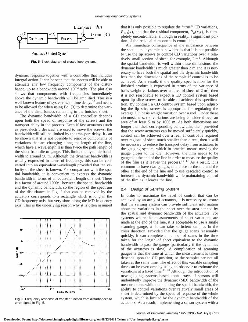
As a result, the dynamic bandwidth of the full arrayscrews can be determined by considering the responsingle screw in the SISO feedback loop in Fig. 5. Whdisturbances,d(t), enter the system, the aim is to choocontrol actions,u(t), that keep the error,e(t), as close aspossible to zero. Figure 6 shows the frequency responsthe transfer function fromd(t) to e(t) for a system consist-ing of a transport delay and screws which have a first or
Fig. 4 Spatial frequency response of screw in Fig. 3.
erms of Use: http://spiedl.org/terms
dese totur
elya
t.dsth
eno
neh ondisonvea-ic
ereidthumthethecyed
s,
r-
eeniblela-
he
idthbe
heof
sedca-st-
heeser anareedly,edill
rs tothebelity
thel torol
esureion
byFor
aregletheablyeic
kent alllingthe
will
theofholee
th a
Two-dimensional control systems
Downl
dynamic response together with a controller that incluintegral action. It can be seen that the system will be ablattenuate any low frequency components of the disbance, up to a bandwidth around 1022 rad/s. The plot alsoshows that components with frequencies immediatabove the dynamic bandwidth will be amplified. This iswell known feature of systems with time delays38 and needsto be allowed for when using Eq.~3! to determine the vari-ance of the disturbances remaining in the finished shee
The dynamic bandwidth of a CD controller depenupon both the speed of response of the screws andtransport delay in the process. Even if fast actuators~suchas piezoelectric devices! are used to move the screws, thbandwidth will still be limited by the transport delay. It cabe shown that it is not possible to remove componentsvariations that are changing along the length of the liwhich have a wavelength less than twice the path lengtthe sheet from die to gauge. This limits the dynamic bawidth to around 50 m. Although the dynamic bandwidthusually expressed in terms of frequency, this can be cverted into an equivalent wavelength provided that thelocity of the sheet is known. For comparison with the sptial bandwidth, it is convenient to express the dynambandwidth in terms of an equivalent length of sheet. This a factor of around 1000:1 between the spatial bandwand the dynamic bandwidth, so the region of the spectrof the disturbance in Fig. 2 that can be removed byactuators corresponds to a rectangle which is long inCD frequency axis, but very short along the MD frequenaxis. This is the underlying reason why it is often assum
Fig. 5 Block diagram of closed loop system.
Fig. 6 Frequency response of transfer function from disturbances toerror signal in Fig. 5.
oaded From: http://electronicimaging.spiedigitallibrary.org/ on 08/23/2013 T
-
e
f,f-
--
that it is only possible to regulate the ‘‘true’’ CD variationPCD(x), and that the residual component,PR(x,t), is com-pletely uncontrollable, although in reality, a significant potion of the residual component is controllable.
An immediate consequence of the imbalance betwthe spatial and dynamic bandwidths is that it is not possto use the lip screws to control CD variations over a retively small section of sheet, for example, 2 m2. Althoughthe spatial bandwidth is well within these dimensions, tdynamic bandwidth is much greater than 2 m and it is nec-essary to have both the spatial and the dynamic bandwless than the dimensions of the sample if control is toachieved. As a result, if the quality specification for tfinished product is expressed in terms of the variancebasis weight variations over an area of sheet of 2 m2, thenit is not reasonable to expect a CD control system baupon lip slice screws to be able to achieve this specifition. By contrast, a CD control system based upon adjuing the lip slice screws is appropriate for regulating taverage CD basis weight variation over a reel. Under thcircumstances, the variations are being considered ovearea of at least 5 m by 1000 m. As both dimensionslonger than their corresponding bandwidths, then, providthat the screw actuators can be moved sufficiently quickcontrol can be achieved over a reel. If control is requirover regions of sheet much smaller than a reel, then it wbe necessary to reduce the transport delay from actuatothe gauging system, which in practice means movinggauge closer to the die. However, the film needs togauged at the end of the line in order to measure the quaof the film as it leaves the process.15–17 As a result, it iscommon to have two gauges, one close to the die andother at the end of the line and to use cascaded controincrease the dynamic bandwidth while maintaining contof the film as it leaves the line.
2.4 Design of Sensing System
In order to maximize the level of control that can bachieved by an array of actuators, it is necessary to enthat the sensing system can provide sufficient informatabout the variations in the sheet over the area definedthe spatial and dynamic bandwidth of the actuators.systems where the measurements of sheet variationsmade at the end of the line, it is acceptable to use a sinscanning gauge, as it can take sufficient samples incross direction. Provided that the gauge scans reasonquickly, it can complete a number of scans in the timtaken for the length of sheet equivalent to the dynambandwidth to pass the gauge~particularly if the dynamicsof the actuators is slow!. A complication of scanninggauges is that the time at which the measurement is tadepends upon the CD position, so the samples are notaken at the same time. The effect of this variable samptime can be overcome by using an observer to estimatevariations at a fixed time.39–44Although the introduction ofnew gauging systems based upon arrays of sensorsundoubtedly improve the dynamic~MD! bandwidth of themeasurements while maintaining the spatial bandwidth,ability to control variations over relatively small areassheet is determined by the speed of response of the wsystem, which is limited by the dynamic bandwidth of thactuators. As a result, implementing a sensor system wi
Journal of Electronic Imaging / July 2001 / Vol. 10(3) / 665
erms of Use: http://spiedl.org/terms
es a
atsrerayen
ntssurwog i
theinof
re-atge’CDb-
e
thcaralalThhemepaurn
remad
noainb
inaplint it
oe ocoun
notonheicuhatt isacmnte
ta-eson-f a
del,theain-to
heias-tto
h offromheettialing
tions these.r-
ethetur-ol-nceom2.
Dly amsr toion,
Duncan
Downl
wide dynamic bandwidth will not on its own improve thoverall response of the system when the process usetuators with a slow response.
One important limitation of all measuring systems thare used on plastic film lines~and on other web processe!is that they are based upon sensors, whether they asingle scanning sensor or an individual sensor in an arthat take measurements that are continuous in one dimsion ~although typically, these continuous measuremeare then sampled to generate a set of discrete meaments!. Since the aim is to measure variations over tdimensions, this means that there is an inherent samplinthe direction perpendicular to the direction of travel~for asingle scanning gauge! or across the array~for a sensorarray!. Because this sampling is an inherent property ofgauge, it is not possible to apply an anti-aliasing filterthis perpendicular direction, so there is the possibilityaliasing occurring.12,37 One way to overcome this problemis to exploit the natural filtering applied by the measument process which does not take a measurementsingle point on the sheet, but instead takes an ‘‘averameasurement over a finite area. For the purposes ofcontrol, the appropriate anti-aliasing filtering and the susequent signal processing can be determined frombS andbD , the spatial and dynamic bandwidths of thactuators.4,26
2.5 The Control Algorithm
The control algorithm should be designed to exploit bothe spatial and dynamic bandwidths of the actuators. Itbe shown4 that, provided the controller contains an integterm, any CD control algorithm will achieve the spatibandwidth, provided that the system remains stable.focus of the control design is therefore to maximize tdynamic bandwidth of the system. To achieve this, sodecoupling of the interaction between the overlapping stial responses of the actuators is necessary which, in trequires an accurate understanding of these spatialsponses. Although many successful CD control systehave been implemented, in practice, it is necessary todress the following issues.
• The true spatial responses of the actuators areknown in practice and, in any case, are unlikely to remconstant. The control algorithm has to be designed torobust to accommodate differences between the nomspatial responses, which are used to design the decoufor the interactions, and the true spatial responses. Asimplest, this can be achieved by turning down the gainthe system, but this degrades the dynamic performancthe system. A more suitable technique detunes the depling used in the CD algorithm,23,27 or uses robust desigtechniques.33,45
• The discussion of both the spatial bandwidths didtake account of the fact that, in practice, there are limitsthe allowable range of inputs to the lip slice screws. Tpresence of constraints on inputs can be problem, partlarly when controlling components of the disturbance thave frequencies close to either of the bandwidths. Itherefore necessary to ensure that the control algorithmcommodates these constraints in an efficient way. A nuber of authors have used constrained one-step ahead co~or variants!,21,46 or applied constrained model predictiv
666 / Journal of Electronic Imaging / July 2001 / Vol. 10(3)
oaded From: http://electronicimaging.spiedigitallibrary.org/ on 08/23/2013 T
c-
a,-
e-
n
a’
n
e
-,-
s-
t
elg
sff-
-
--rol
control~MPC! methods to the problem.35,47,48However, thedimensions of the problem make the on-line implemention of these MPC systems infeasible, particularly on linwhere the sheet velocity is high and the time between ctrol actions is short. This has led to the development onumber of approximate, suboptimal solutions.48 A furtherproblem arises from the uncertainties in the process moas it is not straightforward to determine the behavior ofsystem in the presence of both constraints and uncertties. As a result, suboptimal solutions are often foundwork well in practice as they are more robust.4,48
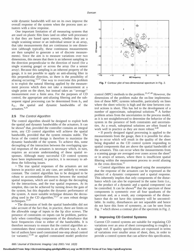
• If poorly designed signal processing is applied to tmeasurements from the gauge, then it is possible for aling to occur which will result in the quality of the sheebeing degraded as the CD control system respondingspatial components that are above the spatial bandwidtthe actuators. This can occur when the measurementsa scanning gauge are averaged over zones across the s4
or in arrays of sensors, where there is insufficient spafiltering within the measurement process to avoid aliasin the cross direction.12
• Control algorithms are designed using the assumpthat the response of the actuators can be expressed aproduct of a dynamic component and a spatial responThis inherently implies that only components of the distubance which can also be expressed in the same form~i.e.,as the product of a dynamic and a spatial component! canbe controlled. It can be shown49 that the spectrum of thescomponents is symmetric over all four quadrants ofspectrum and, as a result, any components of the disbance that do not have this symmetry will be uncontrlable. In reality, disturbances are not separable and hedo not have this form of symmetry, as can be seen frFig. 7 which shows a contour plot of the spectrum in Fig.
3 Improving CD Control Systems
Current CD control systems are suitable for regulating Cvariations over an area of sheet corresponding to roughsingle reel. If quality specifications are expressed in terof variations over smaller areas of sheet, then, in ordeprovide a control system that can achieve this specificat
Fig. 7 Contour plot of two-dimensional spectrum in Fig. 2.
erms of Use: http://spiedl.org/terms
ofperm
tua
s ay t
tion
cuy its.an
onofo
whA
tiononaion
y-nsthtuaar
e aors-thlieb
chto
ha
f tha
d-bentsg.
politysse
bdthim-ed
o
eic
ur-cone othm
betoaDDD
l ofandre-ia-ingents
00rchntsp.
l
nd
oftral
o-
al
for
forpoint
ges:c
r a,m-
ea-
ure-
ghties,’’
cent
n
er
o.
ys-
s:
Two-dimensional control systems
Downl
it is necessary to improve the overall dynamic bandwidththe system. This, in turn, places requirements on theformance on all three components of the control systenamely, the sensors, the control algorithm and the actors.
Sensors:The new generation of array sensors providevery high density of measurements and has the capabilitmeasuring variations over small areas of sheet.10,11,13Theyare therefore immediately suitable for the next generaof control system.
Control algorithm: Designing a control algorithm for asystem with a wider dynamic bandwidth requires an acrate model of the response of the actuators, particularlthe controller is to incorporate the effect of constrainUnder these circumstances, some of the assumptionsapproximations used in the current generation of CD ctrollers may break down. In particular, the assumptionthe separability of the spatial and dynamic componentsthe response may no longer hold as there is no reasonthe underlying response should satisfy this condition.suitable approach may be to use the model identificaand control design techniques based upon two-dimensipolynomial methods, which do not require the assumptof separability.50,51
Actuators: There are two aspects to improving the dnamic bandwidth of the actuators: speeding up the respoof the actuators that move the screws and reducingtransport lag from head box to gauging system. Fast actors for moving screws based upon piezoelectric effectsnow available, so the speed of response aspect can bdressed. The problem of reducing the transport lag is mdifficult. If we start from the premise that the gauging sytem should be placed at the end of the line to measurefinished sheet that goes to the customer, then this impthat, to reduce the transport lag, the actuators have tomoved closer to the end of the line. Given the current tenology, this is not feasible, so a possible compromise ishave a gauging system, close to the die. Ideally, sucmeasuring device would be used in conjunction withseparate array sensing system positioned at the end oline. In principle, all the components exist for creatingCD control system with a sufficiently wide dynamic banwidth to allow variations over small areas of sheet toregulated. However, integrating these individual elemeto form an overall system is clearly a major undertakinThe cost justification for such a development depends uthe benefit provided by being able to achieve a quaspecification over small areas of sheet. It should be strethat the performance of the overall system is determinedthe response of the component with the smallest bandwiFor example, the response of the system will not beproved if the bandwidth of the sensing system is improvwithout a corresponding improvement in the responsethe actuators.
4 Conclusions
This paper has considered the design and performancCD control systems in terms of a spatial and a dynambandwidth. The bandwidths determine the level of distbances that can be removed from the sheet by a CDtroller and depend upon the response and performancthe actuators, the sensing system and the control algori
oaded From: http://electronicimaging.spiedigitallibrary.org/ on 08/23/2013 T
-,-
o
-f
d-
fy
l
ee-
ed-e
ese-
a
e
n
dy.
,f
of
-f.
The specification of the quality of the finished sheet canused to determine the bandwidths that are requiredachieve a suitable level of control, which in turn leads tospecification for the design of the components of the Ccontroller. The bandwidths of the current generation of Ccontrol systems make them suitable for regulating Cvariations over areas of sheet corresponding to a reefilm. However, recent advances in sensing systemscontrol algorithms mean that the individual componentsquired to develop a CD controller, that can regulate vartion over smaller areas of sheet, either exist or are bedeveloped. The challenge is to integrate these componto create a working system.
Acknowledgments
This work was supported in part by Grant No. GR/L186from the UK Engineering and Physical Sciences ReseaCouncil. The author gratefully acknowledges the commeand suggestions from Peter Wellstead and Martin Zarro
References1. R. Wilhelm and M. Fjeld, ‘‘Control algorithms for cross-directiona
control: the state of the art,’’ inProc. 5th IFAC/IMEKO Conf. onInstrumentation and Automation in the Paper, Rubber, Plastics aPolymerisation Industries, pp. 163–174, Antwerp, Belgium~1983!.
2. R. Wilhelm, ‘‘On the controllability of cross-direction variation insheet properties,’’ inProc. Tappi Engineering Conf., pp. 621–629,Boston, MA ~1984!.
3. D. Gorinevsky, R. Vyse, and M. Heaven, ‘‘Performance analysiscross-directional process control using multivariable and specmodels,’’ IEEE Trans. Control Syst. Technol.8~4!, 589–600~2000!.
4. S. Duncan, ‘‘The cross-directional control of web forming prcesses,’’ PhD thesis, University of London, London, UK~1989!.
5. S. Duncan and G. Bryant, ‘‘Spatial controllability of cross-directioncontrol systems for web processes,’’Automatica 33~2!, 139–153~1997!.
6. W. Heath and P. Wellstead, ‘‘Self-tuning prediction and controltwo-dimensional processes. Part 1: Fixed parameter algorithms,’’Int.J. Control62~1!, 65–107~1995!.
7. W. Heath and P. Wellstead, ‘‘Self-tuning prediction and controltwo-dimensional processes. Part 2: Parameter estimation, settracking and offset handling,’’Int. J. Control62~2!, 239–269~1995!.
8. P. Wellstead and M. Zarrop,Self-Tuning Systems, Wiley, Chichester,UK ~1991!.
9. S. Duncan and P. Wellstead, ‘‘Processing data from scanning gau2D reconstruction,’’ inProc. SPIE Process Imaging for AutomatiControl Conf.4188, 38–44, Boston, MA~2000!.
10. R. Pfeifer, P. Williams, and R. Holmes, ‘‘System considerations fofullsheet imaging system,’’ inProc. Joint TAPPI Process ControlElectrical and Engineering Conf. and ISA PUPID 38th Annual Syposium, pp. 131–144, Vancouver, BC, Canada~1998!.
11. P. Hindle and C. Smith, ‘‘Ultra-fast web thickness and coating msurements with true, two-dimensional control,’’ inProc. NIR’94Conf., Lorne, Australia~1994!.
12. J. Skelton, P. Wellstead, and S. Duncan, ‘‘Multiple sensor measments for web products,’’ inProc. 5th European Control Conf., p.F666, Karlsruhre, Germany~1999!.
13. S. Shapiro, R. Vyse, and C. Hagart-Alexander, ‘‘New wet end weimeasurement system opens papemaking optimisation opportunitin Ref. 10, pp. 207–214.
14. E. Heaven, I. Jonsson, T. Kean, M. Maness, and R. Vyse, ‘‘Readvances in cross machine profile control,’’IEEE Control Syst. Mag.14~5!, 35–46~1994!.
15. A. Niemi and C. Backstrom, ‘‘Automatic observation of dry line owire for wet end control of the paper machine,’’ inProc. CPPA Con-trol Systems 92, Conf., pp. 261–265, Whistler BC, Canada~Sept.1992!.
16. A. Kjaer, P. Wellstead, and W. Heath, ‘‘On-line sensing of papmachine wet-end properties: dry-line detector,’’IEEE Trans. ControlSyst. Technol.5~6!, 571–585~1997!.
17. W. Bialkowski, ‘‘Paper machine wet line control,’’ U.S. Patent N4,500,968~1985!.
18. A. El Jai and A. Pritchard, ‘‘Sensors and actuators in distributed stems,’’ Int. J. Control46, 1139–1153~1987!.
19. C. MacCluer,Boundary Value Problems and Orthogonal ExpansionPhysical Problems from a Sobolev Viewpoint, IEEE, New York~1994!.
Journal of Electronic Imaging / July 2001 / Vol. 10(3) / 667
erms of Use: http://spiedl.org/terms
ss
eb
of
ms
n-
or-
er-ari-f.
cal’ in,
ba-
a
ol-
olur-
m-
of
ss-32,
dsCD
ion
icl,’’
m-
g
ited
ine
ofin
l ofms
per
on
lm-
trol
-
o-s,’’
o--
Duncan
Downl
20. S. Duncan, ‘‘Estimating the response of actuators in a crodirectional control system,’’Pulp Paper Canada98~4!, 61–64~1997!.
21. W. Heath, ‘‘Orthogonal functions for cross-directional control of wforming processes,’’Automatica32~2!, 183–198~1995!.
22. A. Featherstone and R. Braatz, ‘‘Control relevant identificationsheet and film processes,’’ inProc. American Control Conf., pp.2692–2696, Seattle, WA~1995!.
23. S. Duncan, ‘‘The design of robust cross-directional control systefor paper making,’’ in Ref. 22, pp. 1800–1805.
24. G. Kastenakis, ‘‘Predicting and verifying the best quality control uder particular conditions,’’Tappi J.73~12!, 203–207~1990!.
25. M. Saucier and A. Steinkirchner, ‘‘Analysis of paper machine perfmance,’’Tappi J.71~4!, 97–102~1988!.
26. D. Gorinevsky, R. Vyse, C. Hagart-Alexander, and M. Heaven, ‘‘Pformance analysis of cross-direction process control using multivable and spectral methods,’’ inProc. CPPA Control Systems 96 Con,pp. 9–14, Halifax, Nova Scotia, Canada~1996!.
27. G. Stewart, G. Dumont, and D. Gorinevsky, ‘‘Design of a practirobust controller for a sampled distributed parameter system,’Proc. IEEE Conf. on Decision and Control, pp. 3156–3161, TampaFL ~1998!.
28. K. Kristinsson and G. Dumont, ‘‘Paper machine cross directionalsis weight control using Gram polynomials,’’ inProc. 2nd IEEE Conf.on Control Applications, pp. 235–240, Vancouver, BC, Canad~1993!.
29. M. Grimble and J. Fotakis, ‘‘The design of strip shape contrsystems for senzimir mills,’’IEEE Trans. Autom. Control27~3!, 656–666 ~1982!.
30. A. Rigopoulos, Y. Arkun, and F. Kayihan, ‘‘Model predictive controf CD profiles in sheet forming processes using full profile distbance models identified by PCA,’’ inProc. American Control Conf.,pp. 1468–1472, Albquerque, NM~1997!.
31. A. Halouskova´, M. Karny, and I. Nagy, ‘‘Adaptive cross-directioncontrol of paper basis weight,’’Automatica29, 425–429~1993!.
32. Z. Nesic, M. Davies, and G. A. Dumont, ‘‘Paper machine data copression using wavelets,’’ inProc. 5th IEEE Conf. on Control Appli-cations, pp. 161–166, Dearborn, MI~1996!.
33. D. Laughlin, M. Morari, and R. Braatz, ‘‘Robust performancecross-directional basis-weight control in paper machines,’’Auto-matica29~6!, 1395–1410~1993!.
34. S. Duncan and K. Corscadden, ‘‘Minimising the range of crodirectional variations in basis weight on a paper machine,’’ in Ref.pp. 161–166.
35. P. Dave, D. Willig, G. Kudva, J. Pekny, and F. Doyle, ‘‘LP methoin MPC of large scale systems: Application to paper-machinecontrol,’’ AIChE J.43~4!, 1016–1031~1997!.
36. S. Duncan and K. Corscadden, ‘‘Mini-max control of cross-directvariations on a paper machine,’’IEE Proc.-D: Control Theory Appl.145~2!, 189–196~1998!.
37. S. Duncan, J. Allwood, W. Heath, and K. Corscadden, ‘‘Dynammodelling of cross-directional actuators: Implications for controIEEE Trans. Control Syst. Technol.8~4!, 667–675~2000!.
38. G. Goodwin, S. Graebe, and M. Salgado,Control System Design,Prentice-Hall, Englewood Cliffs, NJ 2000.
668 / Journal of Electronic Imaging / July 2001 / Vol. 10(3)
oaded From: http://electronicimaging.spiedigitallibrary.org/ on 08/23/2013 T
- 39. L. Bergh and J. MacGregor, ‘‘Spatial control of sheet and film foring processes,’’Can. J. Chem. Eng.65, 148–155~1987!.
40. G. Goodwin, S. Lee, and A. Carlton, ‘‘Application of Kalman filterinto zinc coating mass estimation,’’ inProc. 3rd IEEE Conf. on ControlApplications, pp. 1539–1544, Glasgow, UK~1994!.
41. O. Jacobs, ‘‘Designing feedback controllers to regulate deposmass in hot-dip galvanizing,’’Control Eng. Practice3~11!, 1529–1542 ~1995!.
42. X. Wang, G. Dumont, and M. Davies, ‘‘Estimation in paper machcontrol,’’ IEEE Control Syst. Mag.13~4!, 34–43~1993!.
43. C. Rao, J. Campbell, and J. Rawlings, ‘‘Efficient implementationmodel predictive control for sheet and film forming processes,’’Ref. 30, pp. 2940–2944.
44. S. Duncan, ‘‘Observers and controllers for cross-directional controweb processes,’’ Technical Report No. 806, Control SysteCentre—UMIST, Manchester, UK~1994!.
45. J. VanAntwerp and R. Braatz, ‘‘Robust control of large scale pamachines,’’ inProc. AIChE Annual Meeting, p. 17002, Dallas, TX~1999!.
46. S. Chen and R. Wilhelm, ‘‘Optimal control of cross-machine directiweb profile with constraints on the control effort,’’ inProc. AmericanControl Conf., Minneapolis, MN ~1987!.
47. J. Campbell and J. Rawlings, ‘‘Predictive control of sheet- and fiforming processes,’’AIChE J.44, 1713–1723~1998!.
48. J. VanAntwerp, D. Ma, and R. Braatz, ‘‘When is constrained connecessary for large scale processes,’’ inProc. American ControlConf., pp. 4244–4248, Chicago, IL~2000!.
49. A. Kjaer, ‘‘Modelling, sensing and identification of web-forming processes,’’ PhD thesis, UMIST, Manchester, UK~1994!.
50. P. Wellstead, M. Zarrop, W. Heath, A. Kjaer, and X. Troyas, ‘‘Twdimensional methods for MD and CD estimation: Recent progresin Proc. CPPA Control Systems 96 Conf., pp. 5–8, Halifax, NovaScotia, Canada~1996!.
51. M. Zarrop and X. Troyas, ‘‘Model based predictive control for twdimensional processes,’’Advances in Model Based Predictive Control, Oxford Science, Oxford, UK~1994!.
Stephen Richard Duncan received hisMA degree in physics and theoretical phys-ics from Cambridge University, UK, and hisMSc and PhD degrees in control systemsfrom Imperial College, London. From 1989to 1993 he was a director of Greycon Ltd.,and from 1993 to 1998 he was with theControl Systems Centre, UMIST,Manchester, UK, where he was appointedreader. Since 1998, he has been with theDepartment of Engineering Science at the
University of Oxford, UK, where he is a lecturer. His current re-search interests include the control of industrial processes, distrib-uted parameter systems and the modeling of the dynamics of epi-demics.
erms of Use: http://spiedl.org/terms