Embed Size (px)
Citation preview

TKNTelecommunication
Networks Group
Technical University Berlin
Telecommunication Networks Group
TWIST: A Scalable and ReconfigurableWireless Sensor Network Testbed for
Indoor Deployments
Vlado Handziski, Andreas Kopke,Andreas Willig, Adam Wolisz{handzisk,koepke, willig, wolisz}@tkn.tu-berlin.de
Berlin, November, 2005
TKN Technical Report TKN-05-008
TKN Technical Reports Series
Editor: Prof. Dr.-Ing. Adam Wolisz

Abstract
We present TWIST, a scalable and flexible testbed architecture for indoor deployment ofwireless sensor networks. The design of TWIST is based on an analysis of typical and de-sirable uses of sensor network testbeds. In addition to providing basic services like nodeconfiguration, network-wide programming, out-of-band extraction of debug data and gate-waying of application data, the architecture introduces several novel features, some of themexploiting the capabilities of the USB 2.0 standard. Firstly, TWIST supports different sen-sor node platforms. Secondly, it supports active power-control of the nodes. This enableseasy transition between USB-powered and battery-powered experiments, dynamic selectionof topologies as well as controlled injection of node-failures in the system. Thirdly, TWISTsupports evaluation of both flat and hierarchical sensor networks. The “super nodes” thatform the middle tier of the testbed infrastructure are dual-use devices that can also play arole as part of the sensor network application.
The self-configuration capability, the use of standardized hardware and open-source soft-ware make the TWIST architecture scalable, affordable, and easily replicable. To demonstrateits practical value, we present our experiences with building and using a specific realizationof the TWIST architecture that spans three floors of our office building and supports overone hundred sensor nodes.

TU Berlin
Contents
1 Introduction 2
2 The Design of TWIST: Goals and Rationale 42.1 Helping Designers: Matching System under Examination (SUE) Architecture
and TWIST Architecture . . . . . . . . . . . . . . . . . . . . . . . . . . . . . 42.2 Helping Implementers/Testers: Programming and Time Synchronization . . . 52.3 Helping Experimenters: Power Control . . . . . . . . . . . . . . . . . . . . . . 62.4 Helping Testbed Owners: Management . . . . . . . . . . . . . . . . . . . . . . 6
3 TWIST Architecture 83.1 Sensor Nodes . . . . . . . . . . . . . . . . . . . . . . . . . . . . . . . . . . . . 83.2 Testbed Sockets and USB Cabling . . . . . . . . . . . . . . . . . . . . . . . . 103.3 USB Hubs . . . . . . . . . . . . . . . . . . . . . . . . . . . . . . . . . . . . . . 103.4 Super Nodes . . . . . . . . . . . . . . . . . . . . . . . . . . . . . . . . . . . . 123.5 Server . . . . . . . . . . . . . . . . . . . . . . . . . . . . . . . . . . . . . . . . 133.6 Control Station . . . . . . . . . . . . . . . . . . . . . . . . . . . . . . . . . . . 14
4 The TWIST Instance at the TKN building 154.1 Deployment . . . . . . . . . . . . . . . . . . . . . . . . . . . . . . . . . . . . . 154.2 Usage example . . . . . . . . . . . . . . . . . . . . . . . . . . . . . . . . . . . 16
5 Related Work 18
6 Conclusion 19
Copyright at Technical UniversityBerlin. All Rights reserved.
TKN-05-008 Page 1
TU Berlin
Chapter 1
Introduction
Wireless Sensor Networks (WSNs) are large-scale distributed embedded systems incorporat-ing small, energy- and resource-constrained sensor nodes communicating over wireless media[10]. The design, implementation and evaluation of sensor network applications and commu-nication protocols is a difficult task, considering their distributed nature. The first designsteps can often be made with the help of simulations, which frequently force the designerto make artificial assumptions about traffic, failure patterns and topologies. The later stepsof implementation and evaluation of application performance as well as error resilience andother nonfunctional properties, require the use of real hardware, realistic environments andrealistic experimental setups.
The primary goal of any testbed is to support the design, implementation/test and eval-uation of sensor network applications and protocols. We refer to these as SUE. To facilitateSUE design, it should be possible to implement different network architectures in the testbed,from which the designer can select the best one for his application. To support the implemen-tation/test/debugging phase, functionalities like node (re-)programming as well as collection,processing and displaying of debug data are needed. For evaluation purposes, users shouldhave means to precisely and reproducibly control network topologies, to inject node faults.Besides these development-oriented goals a WSN testbed should be scalable enough to sup-port large-scale deployments with more than just a few dozen nodes while keeping the costsat a reasonable level.
In this paper we describe the design, architecture and deployment of the TKN WirelessIndoor Sensor network Testbed (TWIST). It evolved out of our experiences with the first WSNtestbed [12] deployed at TKN (Telecommunication Networks group at Technical UniversityBerlin) in the framework of the EU IST EYES project.
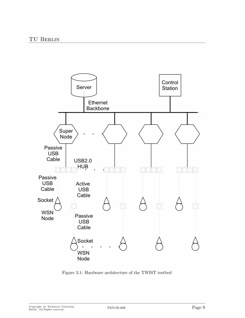
The architecture of TWIST is hierarchical and supports realization of different SUE ar-chitectures. The lowest tier is formed by sensor nodes, which can be of different types. Thesecond tier is formed by super nodes, which are power-unconstrained and have much highercomputational power. The sensor nodes are attached to the super nodes through a USBinfrastructure. A third tier is formed by a dedicated server hosting, for instance, a databaseof the nodes installed in the testbed and their current locations. Finally, the control stationprovides the interface between the user and the testbed.
TWIST is based on cheap off-the-shelf hardware and uses open-source software. It is thus acost-effective and open solution, which can be reproduced by other institutions. Furthermore,
Copyright at Technical UniversityBerlin. All Rights reserved.
TKN-05-008 Page 2

TU Berlin
the openness of the TWIST software gives full flexibility in the use of the testbed.The rest of the paper is organized as follows: in the next Section 2 we give a high-level
view on the design goals and design rationale of the TWIST architecture. The details of ourarchitecture design are explained in Section 3, and the specific instance of TWIST in ourbuilding is described in Section 4. Related work is surveyed in Section 5 and in Section 6 weconclude the paper.
Copyright at Technical UniversityBerlin. All Rights reserved.
TKN-05-008 Page 3

TU Berlin
Chapter 2
The Design of TWIST: Goals andRationale
In this section we explain the design goals and rationale for TWIST. The discussion is struc-tured according to the different phases of sensor network application development: design,implementation/test and experimental evaluation. The management of the testbed itself isalso examined.
2.1 Helping Designers: Matching SUE Architecture and TWISTArchitecture
A number of different wireless sensor network architectures have emerged. In the flat ar-chitecture the sensor network is composed of homogeneous sensor nodes running the sameapplication and protocol code. In a segmented architecture a number of flat networks are cou-pled by gateways. The different flat networks can use incompatible radio technologies. In amulti-tier architecture or hierarchical architecture a sensor network application is partitionedsuch that parts of it run on low-end sensor nodes, whereas other parts run on more capa-ble high-end sensor nodes, which have no energy constraints and have better memory andcomputational resources. In addition to being connected to the low-end nodes, the high-endnodes can interact among themselves and with entities higher in the hierarchy via a backbonenetwork.
These three scenarios can be easily realized with TWIST thanks to the flexible boundarybetween the SUE and testbed functionalities:
• Flat sensor networks: Under this scenario, the boundary between the SUE and thetestbed is just the USB interface on the sensor nodes. The super node and the server /control station exclusively perform testbed functions. The testbed is used to programthe sensor network and to extract debug data or application-related data from the WSN.The extracted data can be preprocessed, compressed, filtered or aggregated already inthe super nodes in a distributed fashion. The debug data is transferred out-of-band anddoes not consume any wireless bandwidth. In cases when even the instrumentation ofSUE code with debug code causes unwanted interactions, then some sensor nodes can
Copyright at Technical UniversityBerlin. All Rights reserved.
TKN-05-008 Page 4

TU Berlin
be programmed with the pure SUE code while others can be dedicated to snoop thenetwork traffic.
• Hierarchical sensor networks: Here, the super nodes can play a role both in the SUEand in the testbed. They do this in two ways. One possibility is to let some of the supernodes act as high-level nodes in the sensor network application and others as testbednodes. The other possibility is to execute both roles at the same time on a single supernode. Hence, the super nodes are dual-use devices. Again, debug data originating insensor nodes is not transmitted over the wireless channel. But in the time-sharing casethe super nodes have to split their computational resources and Ethernet bandwidthbetween SUE and testbed-related functionalities.
• Segmented sensor networks: To implement this scenario, super nodes can be used asgateways between different flat segments.
The communication between the super nodes and the server / control station is carried outusing TCP/IP, making it easy to export the testbed services to (authorized) remote users.
The issue of scalability is not only a general requirement for sensor networks, but thetestbed infrastructure itself also requires scalability in order to support non-trivial numbersof sensor nodes. As an example, let us consider the continuous generation of debug dataor the observation of application-related data. Data from all sensor nodes (or at least fromlarge groups) are required to obtain insight into the operation of the network. For a largesensor network the sheer volume of debug data can be overwhelming, potentially congestingthe backbone network or overloading server and control stations. The super nodes of TWISTcan be used to filter, aggregate, or compress the generated data, thus pushing the “congestionbarrier” towards higher numbers of nodes. The server and control station can be used to storethe aggregated data and present online- and offline evaluations to the user.
2.2 Helping Implementers/Testers: Programming and TimeSynchronization
The implementation and debugging of sensor network applications requires frequent repro-gramming of the nodes with a new (hopefully less buggy) software. There exist approaches(and protocols) to distribute new application code within the sensor network and over thewireless interface [9, 19], but it takes resources on the node, uses valuable wireless bandwidthand may take a long time. TWIST allows reprogramming of sensor nodes using the testbedinfrastructure (“out-of-band programming”), freeing the sensor network programmer fromimplementing code distribution protocols and allowing him to concentrate on other aspects.The reprogramming facility of TWIST is based on the ability of certain microcontrollers tobe reprogrammed over the serial line, exported over the USB interface.
Fixing bugs on single nodes can be a tedious task, it gets even more complicated in adistributed system like a WSN, where individual nodes only contribute small parts to theglobal state and race conditions can cause serious headache to the programmer. Determiningthe current state of the system and how it was entered, is crucial for distributed debugging.However, writing a distributed debugger that allows a complete “happened-before” ordering
Copyright at Technical UniversityBerlin. All Rights reserved.
TKN-05-008 Page 5
TU Berlin
of the events simply exceeds the computational capacities of the sensor nodes. Using thetestbed, a simpler but less precise approach can be taken. When the application dumps debugdata, this data is time stamped by the testbed. The precision of the time stamping usingNetwork Time Protocol (NTP) [13] can be in the range between hundreds of microsecondsand a few milliseconds [3]. The WSN can only send packets every few milliseconds, hence theprecision of the time stamping is often sufficient for debugging and mapping of “WSN-time”to wall-clock time.
2.3 Helping Experimenters: Power Control
A main purpose of a testbed is research. This means that it should enable controlled andreproducible experiments.
Sensor networks differ from other types of networks by the fact that energy aspects are ofcrucial importance. Energy consumption is one of the major performance metrics of sensornetwork protocols and applications. Furthermore, sensor nodes often have a finite energybudgets and sensor networks have highly time-variable topologies due to death of nodes anddeployment of new nodes. This means that applications and protocols must be robust againstnode failures or addition of new nodes. A WSN testbed should offer support for testing thisrobustness under realistic circumstances.
TWIST offers a key facility to realize this: binary power-control. As explained in Sec-tion 3, by switching off the power of sensor nodes, the death of nodes can be emulated.Conversely, by switching them on, the deployment of new nodes is mimicked. Hence, it ispossible to create topologies and inject faults in a controlled fashion. When sensor nodes areboth battery-powered and USB-powered, another option becomes feasible: The nodes areprogrammed and configured while USB power is on. The USB power is switched off for allnodes at the same time, and a common, well-defined starting point is created for measuringthe lifetime achievable with a certain sensor network application / protocol.
Another requirement in the controlled setup of experiments is to have control over thetimes when certain actions like the configuration or start of sensor nodes have to be performed.For example, for investigating the influence of interference on the transmission of data betweentwo nodes, the transmitting node and the interfering node should be started at the same time.Here, the structure of TWIST, where time-synchronized super nodes can tightly control thebehavior of sensor nodes over the USB interface is helpful.
2.4 Helping Testbed Owners: Management
In WSN applications, the unique identifier of a node is usually not overly important. However,this does not apply to testbed management. To keep the testbed operational, it is importantto identify nodes correctly, for instance to make a clear decision on which of the deployednodes is malfunctioning and needs replacement. For the same reason, the exact position ofnodes is also helpful.
The exchange of nodes is a frequent event in a testbed. Therefore, TWIST separates nodeidentifiers from the locations where nodes are attached to the testbed. In fact, in TWISTthe sensor nodes are plugged into fixed USB sockets, which have unique identifiers and a
Copyright at Technical UniversityBerlin. All Rights reserved.
TKN-05-008 Page 6

TU Berlin
priori known the geographic locations. The USB interface on the super nodes detects whena node is plugged into a socket. As a result, a software event is triggered. On receiving suchan event, the super node extracts the manufacturer serial number from the event data anddetermines the unique node identification (nodeID). Then it registers the binding betweenthe node and the socket identifier in a database on the server. This database also keepsthe association between the socket identifiers and their geographical positions. This way itis possible to put nodes into arbitrary sockets and to automatically keep the database in aconsistent state. Furthermore, it is an easy task to figure out the precise position of a sensornode given its identification, to determine all sensor node identifications pertaining to a givengeographical area and so forth. The ability to identify nodes allows to track nodes with, forexample, faulty sensors. It also permits storing per-node configuration and calibration datain the database.
As a secondary benefit, the localization information can be made available to the SUE.The SUE implementer hence does not need to implement localization algorithms on his ownand can concentrate on the problem at hand. When, by chance, the problem happens to bethe implementation and test of a localization algorithm, the known socket positions providea ground truth against which the new algorithm can be compared. Similar arguments holdtrue for the time synchronization capabilities of TWIST.
In the next section we provide a more detailed discussion of the TWIST architecture.
Copyright at Technical UniversityBerlin. All Rights reserved.
TKN-05-008 Page 7

TU Berlin
Chapter 3
TWIST Architecture
Figure 3.1 depicts the hardware architecture of TWIST. In the following we describe the mostimportant characteristics of the testbed entities, starting from the lowest layer, comprised bythe sensor nodes, moving up to the testbed backbone, with the attached server and controlstation.
3.1 Sensor Nodes
As main hardware units of the SUE the sensor nodes need a set of hardware capabilitiesfacilitating their seamless integration with the rest of the testbed infrastructure. Accordingto the identified core functionalities in Section 2 they have to expose suitable hardwareinterfaces that support external powering, reprogramming, as well as out-of-band exchangeof configuration, debug and application data. Traditionally, these functions have been servedby dedicated interfaces: power supply bus, JTAG for programming and debugging, RS-232for serial communication, etc. This was significantly complicating the hardware and softwareintegration between the SUE and the tester, making customized hardware solutions necessary,and driving the costs for even simple testbed configurations prohibitively high.
Recently, several WSN node platforms have emerged using Universal Serial Bus (USB)as standardized hardware interface. Thanks to the features of the USB specification andthe flexibility of the current UART-to-USB chips, this hardware interface is able to replacealmost all of the custom interfaces, simplifying integration of the sensor nodes with externalsystems. This migration to a single standardized interface drastically lowers the costs for thetestbed due to the reduced prices of the components as a result of the economies of scale.
The overall architecture of the TWIST is crucially centered on the use of the USB inter-face. By relying on this open standard, we are able to support a heterogeneous mixture ofWSN platforms as long as they export the above listed capabilities (power-supply, program-ming and communication) via a standard-compliant USB interface. At the moment, boththe eyesIFX [7] and the Telos [15] mote families satisfy the above conditions and have beensuccessfully interfaced with TWIST.
On the software side, the operating system running on the sensor nodes has to satisfyseveral basic requirements. First, it has to provide a suitable execution environment for theapplication logic of the SUE. Secondly, it should support node configuration, instrumentation
Copyright at Technical UniversityBerlin. All Rights reserved.
TKN-05-008 Page 8
TU Berlin
Figure 3.1: Hardware architecture of the TWIST testbed
Copyright at Technical UniversityBerlin. All Rights reserved.
TKN-05-008 Page 9

TU Berlin
of the application code and allow for out-of-band communication with the super nodes overthe USB infrastructure.
TinyOS [8, 4] satisfies these requirements and can be run both on the Telos and the eye-sIFX platforms. It provides a generic and lightweight execution platform for sensor networkapplications. TinyOS is already shipped with components that support communications overthe serial interface using framed protocol similar to PPP/HDLC. On top of this protocol,TinyOS components have been developed that enable printf-like logging as well as bridgingdebug and application messages. Using tools like Pytos [17], even more powerful, RPC-likeinteractions can be supported.
3.2 Testbed Sockets and USB Cabling
Seen as plain hardware, a testbed socket is nothing more than the point where the USBinterface of the sensor node attaches to the USB infrastructure of the testbed. As explainedin Section 2.4, the logical significance of this point for the TWIST architecture is, however,much greater.
The sockets are connected to the rest of the testbed using a combination of passive andactive USB cables, depending on the distance between the location of the socket and the nextelement of the infrastructure – the USB hubs. Using passive cables a maximum distance of5 m can be bridged. For greater distances, “active USB cables” can be used (single port USBhubs with fixed cable), or several USB hubs can be daisy-chained together.
(a) (b)
Figure 3.2: (a) Telos mote in a testbed socket; (b) Super node and USB-hub arrangement
3.3 USB Hubs
The hubs are the central element of the TWIST USB infrastructure and provide support forsome of the most important features of the TWIST architecture.
At the most basic level, the USB hub is a multiplexing device that enables us to breakthe one-to-one correspondence between the sensor nodes and the second-level testbed devices,
Copyright at Technical UniversityBerlin. All Rights reserved.
TKN-05-008 Page 10
TU Berlin
typical for many of the existing WSN testbeds. This enables significant cost savings withoutcompromising any of the testbed functionality. Even more, the USB hubs give TWIST one ofits most powerful capability: the binary power-control over the sensor nodes in the testbed.
The USB Hub Specification 2.0 requires that self-powered hubs support port power switch-ing. By sending a suitable USB control message, the software can control the power state ofa given port on the hub, effectively enabling/disabling the power supply for any downstreamdevice(s) attached. In the case of TWIST, these downstream devices are the sensor nodesattached to the testbed sockets. This means that we are able to individually control thepower supply of any sensor node in the testbed by simply issuing a suitable USB controlmessage to that particular hub to which the corresponding testbed socket is connected.
Depending on whether the sensor node attached to the socket has a battery or not, thisenables us to perform four different transitions:
• from “USB-powered” state into “off” state
• from “off” state into “USB-powered” state
• from “USB-powered”state into “battery-powered” state
• from “battery-powered” state into “USB-powered” state
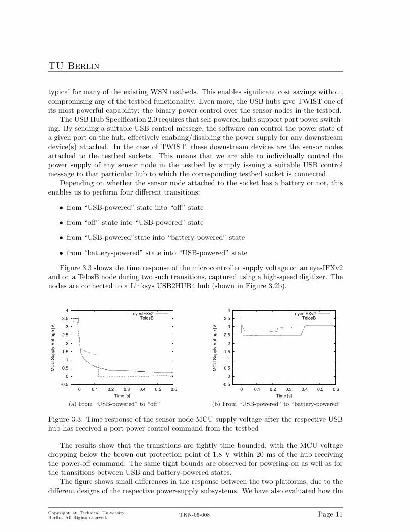
Figure 3.3 shows the time response of the microcontroller supply voltage on an eyesIFXv2and on a TelosB node during two such transitions, captured using a high-speed digitizer. Thenodes are connected to a Linksys USB2HUB4 hub (shown in Figure 3.2b).
-0.5
0
0.5
1
1.5
2
2.5
3
3.5
4
0 0.1 0.2 0.3 0.4 0.5 0.6
MCU
Sup
ply
Volta
ge [V
]
Time [s]
eyesIFXv2TelosB
(a) From “USB-powered” to “off”
-0.5
0
0.5
1
1.5
2
2.5
3
3.5
4
0 0.1 0.2 0.3 0.4 0.5 0.6
MCU
Sup
ply
Volta
ge [V
]
Time [s]
eyesIFXv2TelosB
(b) From “USB-powered” to “battery-powered”
Figure 3.3: Time response of the sensor node MCU supply voltage after the respective USBhub has received a port power-control command from the testbed
The results show that the transitions are tightly time bounded, with the MCU voltagedropping below the brown-out protection point of 1.8 V within 20 ms of the hub receivingthe power-off command. The same tight bounds are observed for powering-on as well as forthe transitions between USB and battery-powered states.
The figure shows small differences in the response between the two platforms, due to thedifferent designs of the respective power-supply subsystems. We have also evaluated how the
Copyright at Technical UniversityBerlin. All Rights reserved.
TKN-05-008 Page 11

TU Berlin
time response depends on the length of the USB cabling between the node and the hub. Theresults (not presented here for lack of space) show that for the lengths we have in our localTWIST instance, i.e. for up to 10 m of USB cabling, the effects are negligible.
The quick time response, as demonstrated by the above results, makes this power-controlcapability one of the most useful features of the TWIST architecture.
It is important to note that in our testing we have detected several hubs on the marketthat claim to fully support the USB 2.0 standard, but fail to support the port power-controlfeature. This function is seldom used by normal “home” users, and it requires additionalpower-control circuitry in the hub, so we suspect that many vendors have decided to silentlydrop the support in order to drive the manufacturing costs for the hubs down. From ourextensive testing of different hubs, we can conclude that the problem is present in almost allhubs having a controller chip from Genesys Logic. The ones that fully support the standardtend to have a controller chip produced by NEC. In particular, we can confirm the properfunctioning of the DUB-H4 rev.A1 hub from D-Link (now out of production, the later revisionsB1, B2 and B3 silently ignore the port power-control commands) and the USB2HUB4 fromLinksys which is used at our local TWIST instance.
3.4 Super Nodes
If TWIST only relied on the USB infrastructure, it would have been limited to 127 USBdevices (both hubs and sensor nodes) with a maximum distance of 30 m between the controlstation and the sensor nodes (achieved by daisy-chaining of up to 5 USB hubs). While suitablefor small to medium size testbeds [16], these limitations are not compatible with our goalsfor scalability of the architecture and support for geographically extensive deployments.
To genuinely tackle the scalability problem, a distributed solution is needed that willspread the testbed functionality among multiple entities. These super nodes have to be ableto interface with the previously described USB infrastructure. In addition, they have tosupport a secondary communication technology that does not have the size and cable lengthlimits of the USB standard, and forms the testbed backbone to which the server and controlstations can be attached. Finally, adequate computational, memory and energy resources areneeded.
Optimally, a device is needed that can satisfy the requirements, while keeping the expensesfor a medium to large-scale testbed to a reasonable level. In this sense, the class of 32-bitembedded devices used for attaching networked storage seems as a very promising alternativesince they offer a very attractive cost/performance ratio. At the same time, these devices havesimilar capabilities as the so-called “high-end wireless sensor nodes” or “microservers” [6],enabling dual use of the super nodes as parts of the testbed and as parts of the SUE.
We are using the Network Storage Link for USB2.0 (NSLU2) device from Linksys (de-picted on Figure 3.2b) as super nodes. The NSLU2 costs about 80 e. It has two USB2.0ports, uses a IXP420 processor from Intel’s XScale family (clocked at 133 MHz), has 32 MB ofSDRAM and 8 MB of flash as persistent storage. One particular feature of the IXP4xx familyare the two integrated “Network Processor Engines (NPE)” that implement, among else, twofull Ethernet MAC and physical layer units with the related packet-processing functionality.
For testbed usage, we replace the Linksys-supplied operating system support for the
Copyright at Technical UniversityBerlin. All Rights reserved.
TKN-05-008 Page 12

TU Berlin
NSLU2 with a customized OpenSlug [14] distribution of Linux. OpenSlug is a variant ofthe OpenEmbedded [11] source distribution of Linux that is specially adapted for use onembedded devices.
Our customization is motivated by the need to change the default “self-healing” behaviorof the Linux kernel when dealing with errors in the communication between the USB hostcontroller and attached USB hubs. We rely on the user-space libusb library for injecting con-trol messages that trigger the explained port power-control functions. This library, however,bypasses the USB hub drivers in the Linux kernel. When there are hubs downstream fromthe powered-off port (i.e. we are controlling the power of a sensor node that is connected withan active cable), this will cause loss of the keep-alive messages between the host controllerand the USB hub, which in turn causes the kernel to reset and subsequently re-power thewhole USB subsystem, including the sensor node that we wanted to turn-off.
The effective management of testbeds with large number of super nodes requires self-configuration capabilities. For the most basic system parameters, like the super node IPaddress and the address of the DNS server, we rely on the DHCP protocol. Time synchro-nization is achieved using NTP.
Because of the limited flash memory on the super nodes, the root and the swap file systemshave to be provided over the network using NFS. To avoid maintenance of as many separatefile system images as there are super nodes in the network, the UnionFS concept [21] is usedto separate between a common file system part (shared by all super nodes and exported inread-only mode) and a private per-super-node part (exported in read-write mode to eachsuper node separately).
3.5 Server
The server and the control stations must interact with the super nodes using the testbedbackbone, so they have to support the same communication technology. Due to the criticalrole of the server (it contains the testbed database, provides persistent storage for debug andapplication data from the SUE, runs the daemons that support the system services in thenetwork, etc.) its hardware resources should be adequately dimensioned to guarantee highlevels of availability. For example, we are currently using an Intel Pentium 4 machine with3.2 GHz CPU, 2 GB of RAM as well as 4x200 GB of HD space organized as RAID5.
The operating software support on the server is also based on Linux, at the moment avanilla Fedora Core 3 server installation. For the management of the super node network,the server runs the DHCP, DNS, NTP, and NFS daemons, as well as the UnionFS kernelmodule.
At the heart of the server is the PostgreSQL database that stores a number of tables in-cluding configuration data like the registered nodes (identified by the NodeIDs), the socketsand their geographical positions (identified by the SocketIDs) as well as the dynamic bind-ings between the SocketIDs and NodeIDs. The database is also used for recording debug andapplication data from the SUE. An important reason for choosing PostgreSQL is the avail-ability of the PostGIS extension that enables us to represent the locations of the sockets in anatural 3D coordinate system and provides support for spatial queries and experimentationwith location-based services.
Copyright at Technical UniversityBerlin. All Rights reserved.
TKN-05-008 Page 13

TU Berlin
3.6 Control Station
Any normal workstation-class machine that is attached to the testbed backbone can serve asa control station. The required systems software is fairly standard, any Linux distributioncan be used. The interesting aspect, however, is how the control station acts in controllingexperiments, in configuring nodes and network topologies etc.
Our current solution consists of two parts. On the one hand, we have developed a numberof Python scripts which run locally on the super nodes and provide functionalities like sensornode programming, executing power control, collecting debug and application data, etc. Onthe other hand, the actual invocation of these scripts is done by the control station using sshremote command execution. Without further optimization, the control station would have tolog onto the super nodes serially and invoke the Python scripts. Clearly, this would require alot of time when activities involving all the nodes (like reprogramming) have to be executed.
To speed up such tasks, we use a hierarchical threading approach to exploit parallelism:the control station first creates a separate thread of control for each of the super nodes.Every such thread starts the Python scripts on the super node via the ssh remote commandexecution. Each of these Python scripts, in turn, create separate threads (on the super node)for each of the attached sensor nodes.
In this way, by utilizing the natural parallelism in the system, we are able to executenetwork wide tasks in approximately the same amount of time as it would have taken ona single sensor node. For example, programming a single sensor node with the TinyOSSurgeTelos application takes about 16 s on the TelosB nodes. For a 30 node sensor network,a linear execution would require 8 minutes. Using the parallel approach we are able toprogram the whole network in under 25 s, making rapid edit/compile/run cycles possible.
Copyright at Technical UniversityBerlin. All Rights reserved.
TKN-05-008 Page 14

TU Berlin
Chapter 4
The TWIST Instance at the TKNbuilding
In this section we present our experiences deploying a large scale instance of TWIST in ouroffice building. We also give one concrete example how the testbed can support a buildingautomation related experiment.
4.1 Deployment
Figure 4.1: Node placement on the 4th floor
The local instance of TWIST spans three floors of our office building. Currently, wehave 90 fixed locations for nodes with known positions and in addition to them 90 free slotson the USB hubs. We used 37 NSLU2s, 53 USB hubs and about 600m of USB cables.The NSLU2s communicate over Ethernet, here we benefited from the fact that our Ethernetcabling was over-dimensioned with two Ethernet cables per room. This is a very comfortablesituation, but not available everywhere. An alternative is a USB-to-WLAN adapter that canbe attached to the free port of the NSLU2 and establish a backbone network using WLAN.
Copyright at Technical UniversityBerlin. All Rights reserved.
TKN-05-008 Page 15

TU Berlin
0
10
20
30
40
50
60
70
06/09 07/09 08/09 09/09 10/09 11/09 12/09 13/09 14/09 15/09
Ligh
t int
ensi
ty [l
x]
Time [day/month]
Door (N0)Window (N31)
Figure 4.2: Illumination differences measured in the same room
Considering the placement, we decided to install two sockets in each room. This providestwo fixed and known locations for nodes per room. Having at least two nodes per room isenough to give some insight into the spatial distribution of values like light (see Figure 4.2)and temperature, also allowing some cross-comparison of sensors of the same type on the twonodes. The node placement is shown in Figure 4.1. This figure also shows the exact locationof the sockets, measured after the installation. The sockets are placed 1 m and 4 m from thewindow, and 1.5m from each wall. For the large rooms, the story is a bit different. In orderto keep the distances comparable, we installed four sockets in the large rooms. Any sparser,more random placement of the nodes can be emulated using the power control feature of thetestbed.
The testbed is installed in our normal office building, and we did not want to let peopletrip over dangling wires. We hence placed the wires neatly into cable channels that aremounted at the ceiling. To connect a node to a socket, we simply connect it to the USBcable and fix it at the cable channel as shown in Figure 3.2a. This also means that the nodeis about 4 cm below the ceiling.
4.2 Usage example
As a usage example, we present a distributed experiment to measure the illumination rate ofchange of using the testbed equipped with eyesIFX nodes. Figure 4.3 shows how often the
Copyright at Technical UniversityBerlin. All Rights reserved.
TKN-05-008 Page 16

TU Berlin
Time [hour:minute]
Nod
e
14:30 17:30 20:30 23:30 1:30 3:30 5:30 7:30 9:30 11:30 14:30
0313029333210
812
697
114521
2019
Figure 4.3: Light traffic intensity matrix, September 12th, 2005
light sensors noticed “significant” illumination changes during a single day. The measurementused a subset of the testbed on the 4th floor. The x-axis denotes the time in 15min intervals,the y-axis uses the Euclidean distance (shown in Figure 4.1) to embed the two-dimensionalplacement of the nodes into one-dimension. The gray scaling indicates how many changeswere observed by the light sensors, white denotes zero changes and black denotes more than32 changes within a 15 min interval. During the night there is no change in the illumination,but that is not surprising. The plot makes the correlations in space and time of illuminationchanges visible. On this day, we had a thunderstorm and one flash at about 9 am was pickedup by all light sensors, except those on nodes 19 and 20, which picked up an earlier flash.We did not want to loose data, hence we first stored it into the local flash and subsequentlydumped it over the testbed.
Copyright at Technical UniversityBerlin. All Rights reserved.
TKN-05-008 Page 17
TU Berlin
Chapter 5
Related Work
MoteLab [20] is a very popular WSN testbed solution. It provides Ethernet back-channelto each sensor node in the network by attaching a dedicated Stargate board [2]. The inter-action between the users and the testbed is batch-oriented and is controlled via a dynamicweb interface supported by a back-end database. Like MoteLab, the Kansei testbed [18]also uses Stargate boards, but it allows richer interaction with the SUE. It uses the EmStardevelopment system for Linux-based WSNs [5] and, similarly to TWIST, allows evaluation ofboth flat and hierarchical WSNs with different communication technologies. In contrast toTWIST, these testbeds use one-to-one mapping between the sensor nodes and the “concen-trators”. This and the custom nature of the “concentrators” make the above solutions muchmore expensive than TWIST.
The Omega architecture [16] resembles the lower tier of TWIST. Both testbeds rely on thestandardized USB interface available on some of the newer mote platforms and use USB-hubsto bridge the 5 m length barrier. Nevertheless, the Omega is not utilizing the features of theUSB 2.0 standard and is not exporting a power-control function to its users. This is one ofthe main features of TWIST and is providing high flexibility. The Omega design is also lessscalable. The USB-hub daisy-chaining approach taken in Omega can only scale up to 127USB devices. With the super node tier, TWIST is not suffering from such restrictions.
The TWIST architecture does not impose any policy for handling concurrent use of thetestbed resources by different users. When simple “cooperative” scheduling is not sufficient,more sophisticated solutions like Mirage [1] can be employed.
Copyright at Technical UniversityBerlin. All Rights reserved.
TKN-05-008 Page 18

TU Berlin
Chapter 6
Conclusion
The design of TWIST presented in this paper addresses many of the needs we have identifiedfor wireless sensor network testbeds: support for different application network architectures,control over the network topology, fast reprogramming, distributed debugging and a highdegree of scalability. We have also demonstrated the feasibility of the TWIST architectureby building a large-scale testbed in our building.
TWIST is based on affordable hardware components and uses open-source software com-ponents. This makes TWIST a valuable template that other researchers can use to createtheir own testbeds.
In this paper we have concentrated mainly on the hardware aspects of TWIST. We cur-rently focus on extending the software support. Our existing script-based approach is effectivebut lacks reusability. To attack this problem we are working on a solution that is based onan object-oriented representation of the important testbed entities and their capabilities. Tohide the distributed nature of these objects we consider using a middleware that providesremote method invocation, an object repository, object persistence and other services.
Copyright at Technical UniversityBerlin. All Rights reserved.
TKN-05-008 Page 19

TU Berlin
Bibliography
[1] Brent N. Chun, Philip Buonadonna, Alvin AuYoung, Chaki Ng, David C. Parkes, JeffreyShneidman, Alex C. Snoeren, and Amin Vahdat. Mirage: A microeconomic resourceallocation system for sensornet testbeds. In Proceedings of the 2nd IEEE Workshop onEmbedded Networked Sensors, May 2005.
[2] Crossbow. Stargate. http://www.xbow.com/Products/XScale.htm.
[3] Jeremy Elson, Lewis Girod, and Deborah Estrin. Fine-grained network time synchro-nization using reference broadcasts. In Proc. Fifth Symposium on Operating SystemsDesign and Implementation (OSDI 2002), December 2002.
[4] David Gay, Philip Levis, Robert von Behren, Matt Welsh, Eric Brewer, and DavidCuller. The nesc language: A holistic approach to networked embedded systems. InProceedings of the ACM SIGPLAN 2003 Conference on Programming Language Designand Implementation (PLDI), pages 1–11, New York, NY, USA, 2003. ACM Press.
[5] L. Girod, J. Elson, A. Cerpa, T. Stathopoulos, N. Ramanathan, and D. Estrin. Em-star: a software environment for developing and deploying wireless sensor networks. InProceedings of USENIX General Track 2004, Boston, MA, USA, June 2004.
[6] Lewis Girod, Thanos Stathopoulos, Nithya Ramanathan, Jeremy Elson, Deborah Es-trin, Eric Osterweil, and Tom Schoellhammer. A system for simulation, emulation, anddeployment of heterogeneous sensor networks. In SenSys ’04: Proceedings of the 2ndinternational conference on Embedded networked sensor systems, pages 201–213, NewYork, NY, USA, 2004. ACM Press.
[7] V. Handziski, J. Polastre, J. H. Hauer, and C. Sharp. Flexible hardware abstraction ofthe ti msp430 microcontroller in tinyos. In Proceedings of the Second ACM Conferenceon Embedded Networked Sensor Systems (SenSys), pages 277–278, Baltimore, MD, USA,November 2004. ACM Press.
[8] Jason Hill, Robert Szewczyk, Alec Woo, Seth Hollar, David E. Culler, and Kristofer S. J.Pister. System Architecture Directions for Networked Sensors. In Architectural Supportfor Programming Languages and Operating Systems, pages 93–104, 2000. TinyOS isavailable at http://webs.cs.berkeley.edu.
[9] Jonathan W. Hui and David Culler. The dynamic behavior of a data dissemination pro-tocol for network programming at scale. In Proceedings of the Second ACM Conferenceon Embedded Networked Sensor Systems (SenSys), 2004.
Copyright at Technical UniversityBerlin. All Rights reserved.
TKN-05-008 Page 20

TU Berlin
[10] Holger Karl and Andreas Willig. Protocols and Architectures for Wireless Sensor Net-works. John Wiley & Sons, Chichester, 2005.
[11] Michael Lauer. Building linux distributions with bitbake and openembedded. In Pro-ceedings of the Free and Open Source Developers’ European Meeting (FOSDEM 2005),Brussels, Belgium, February 2005.
[12] Suet Fei Li, Vlado Handziski, Adreas Kopke, Martin Kubisch, and Adam Wolisz. A wire-less sensor network testbed supporting controlled in-building experiments. In Proceedingsof the 12th International Conference Sensor 2005, volume 1, Nuremberg, Germany, May2005.
[13] David L. Mills. Network time protocol (version 3) specification, implementation andanalysis. RFC 1305, 1992.
[14] The openslug linux distribution. http://www.nslu2-linux.org/wiki/OpenSlug/HomePage.
[15] Joseph Polastre, Robert Szewczyk, and David Culler. Telos: Enabling ultra-low powerwireless research. In Proceedings of the Fourth International Conference on InformationProcessing in Sensor Networks (IPSN’05), Special Track on Platform Tools and DesignMethods for Network Embedded Sensors (SPOTS, 2005.
[16] Omega testbed at uc berkeley, telos (revision b) 802.15.4 wireless sensor network. http://omega.cs.berkeley.edu/.
[17] Pytos development environment. http://nest.cs.berkeley.edu/nestfe/index.php/Pytos Development Environment.
[18] Ohio State University. Kansei: Sensor testbed for at-scale experiments. In Poster, 2ndInternational TinyOS Technology Exchange, February 2005.
[19] Chieh-Yih Wan, Andrew T. Campbell, and Lakshman Krishnamurthy. Psfq: A reliabletransport protocol for wireless sensor networks. In Proc. First ACM Intl. Workshop onWireless Sensor Networks and Applications (WSNA’02), Atlanta, GA, 2002.
[20] Geoffrey Werner-Allen, Pat Swieskowski, and Matt Welsh. Motelab: A wireless sensornetwork testbed. In Proceedings of the Fourth International Conference on InformationProcessing in Sensor Networks (IPSN’05), Special Track on Platform Tools and DesignMethods for Network Embedded Sensors (SPOTS), 2005.
[21] C. P. Wright, J. Dave, P. Gupta, H. Krishnan, D. P. Quigley, E. Zadok, and M. N.Zubair. Versatility and unix semantics in namespace unification. ACM Transactions onStorage (TOS), 1(4), November 2005.
Copyright at Technical UniversityBerlin. All Rights reserved.
TKN-05-008 Page 21