Embed Size (px)
Citation preview
Manual
TwinCAT MC Camming
TwinCAT
1.02015-07-06TF5050
VersionDateOrder No.

Table of contents
Table of contents1 Foreword .................................................................................................................................................... 5
1.1 Notes on the documentation............................................................................................................. 51.2 Safety instructions ............................................................................................................................ 6
2 Overview..................................................................................................................................................... 7
3 Cam plates ................................................................................................................................................. 83.1 MC_CamTableSelect........................................................................................................................ 83.2 MC_CamOut................................................................................................................................... 103.3 MC_CamIn...................................................................................................................................... 123.4 MC_CaminAppendix....................................................................................................................... 153.5 MC_CamScaling............................................................................................................................. 18
4 Multi cam plates....................................................................................................................................... 204.1 MC_CamIn_V2 ............................................................................................................................... 204.2 MC_CamAdd .................................................................................................................................. 234.3 MC_CamExchange......................................................................................................................... 264.4 MC_CamRemove ........................................................................................................................... 294.5 MC_CamScaling_V2 ...................................................................................................................... 31
5 Motion functions...................................................................................................................................... 335.1 MC_ReadMotionFunction ............................................................................................................... 335.2 MC_ReadMotionFunctionPoint....................................................................................................... 355.3 MC_WriteMotionFunction ............................................................................................................... 365.4 MC_WriteMotionFunctionPoint ....................................................................................................... 375.5 MC_SetCamOnlineChangeMode ................................................................................................... 385.6 MC_ReadMotionFunctionValues .................................................................................................... 39
6 Status........................................................................................................................................................ 416.1 MC_ReadCamTableSlaveDynamics .............................................................................................. 416.2 MC_CamInfo................................................................................................................................... 436.3 MC_CamInfo_V2 ............................................................................................................................ 456.4 MC_ReadCamTableCharacteristics ............................................................................................... 476.5 MC_ReadCamTableMasterPosition ............................................................................................... 48
7 Data type .................................................................................................................................................. 517.1 Data type MC_CAM_ID .................................................................................................................. 517.2 Data type MC_CAM_REF............................................................................................................... 527.3 Data type MC_CamActivationMode................................................................................................ 537.4 Data type MC_CamScalingMode ................................................................................................... 577.5 Data type MC_CamInfoData........................................................................................................... 607.6 Data type MC_InterpolationType .................................................................................................... 617.7 Data type MC_MotionFunctionPoint ............................................................................................... 627.8 Data type MC_MotionFunctionPoint_ID ......................................................................................... 637.9 Data type MC_MotionFunctionType ............................................................................................... 647.10 Data type MC_MotionPointType..................................................................................................... 657.11 Data type MC_TableCharacValues ................................................................................................ 667.12 Data type MC_TableErrorCodes .................................................................................................... 677.13 Data type MC_TableType............................................................................................................... 67
TwinCAT MC Camming 3Version 1.0

Table of contents
7.14 Data type MC_ValueSelectType..................................................................................................... 677.15 Data type MC_StartMode ............................................................................................................... 687.16 Data type ST_CamInOptions.......................................................................................................... 697.17 Data type CamMasterData ............................................................................................................. 707.18 Data type MC_CamOperationMode ............................................................................................... 707.19 Data type ST_CamScalingData...................................................................................................... 71
8 Example programs .................................................................................................................................. 72
TwinCAT MC Camming4 Version 1.0
Foreword
1 Foreword
1.1 Notes on the documentationThis description is only intended for the use of trained specialists in control and automation engineering whoare familiar with the applicable national standards.It is essential that the following notes and explanations are followed when installing and commissioningthese components.
The responsible staff must ensure that the application or use of the products described satisfy all therequirements for safety, including all the relevant laws, regulations, guidelines and standards.
DisclaimerThe documentation has been prepared with care. The products described are, however, constantly underdevelopment.For that reason the documentation is not in every case checked for consistency with performance data,standards or other characteristics.In the event that it contains technical or editorial errors, we retain the right to make alterations at any timeand without warning.No claims for the modification of products that have already been supplied may be made on the basis of thedata, diagrams and descriptions in this documentation.
TrademarksBeckhoff®, TwinCAT®, EtherCAT®, Safety over EtherCAT®, TwinSAFE®, XFC®and XTS® are registeredtrademarks of and licensed by Beckhoff Automation GmbH.Other designations used in this publication may be trademarks whose use by third parties for their ownpurposes could violate the rights of the owners.
Patent PendingThe EtherCAT Technology is covered, including but not limited to the following patent applications andpatents:EP1590927, EP1789857, DE102004044764, DE102007017835with corresponding applications or registrations in various other countries.
The TwinCAT Technology is covered, including but not limited to the following patent applications andpatents:EP0851348, US6167425 with corresponding applications or registrations in various other countries.
EtherCAT® is registered trademark and patented technology, licensed by Beckhoff Automation GmbH,Germany
Copyright© Beckhoff Automation GmbH & Co. KG, Germany.The reproduction, distribution and utilization of this document as well as the communication of its contents toothers without express authorization are prohibited.Offenders will be held liable for the payment of damages. All rights reserved in the event of the grant of apatent, utility model or design.
TwinCAT MC Camming 5Version 1.0
Foreword
1.2 Safety instructions
Safety regulationsPlease note the following safety instructions and explanations!Product-specific safety instructions can be found on following pages or in the areas mounting, wiring,commissioning etc.
Exclusion of liabilityAll the components are supplied in particular hardware and software configurations appropriate for theapplication. Modifications to hardware or software configurations other than those described in thedocumentation are not permitted, and nullify the liability of Beckhoff Automation GmbH & Co. KG.
Personnel qualificationThis description is only intended for trained specialists in control, automation and drive engineering who arefamiliar with the applicable national standards.
Description of symbolsIn this documentation the following symbols are used with an accompanying safety instruction or note. Thesafety instructions must be read carefully and followed without fail!
DANGER
Serious risk of injury!Failure to follow the safety instructions associated with this symbol directly endangers thelife and health of persons.
WARNING
Risk of injury!Failure to follow the safety instructions associated with this symbol endangers the life andhealth of persons.
CAUTION
Personal injuries!Failure to follow the safety instructions associated with this symbol can lead to injuries topersons.
Attention
Damage to the environment or devicesFailure to follow the instructions associated with this symbol can lead to damage to the en-vironment or equipment.
Note
Tip or pointerThis symbol indicates information that contributes to better understanding.
TwinCAT MC Camming6 Version 1.0

Overview
2 OverviewIn many applications it is necessary to synchronize two or more axes. Axes can be coupled together in theTwinCAT NC PTP. A master axis is then actively controlled, and the position of one or more coupled slaveaxes is synchronously controlled by the NC.
The simplest type of coupling is linear coupling with a fixed ratio of transmission (electronic gearing).
Some applications require a more complex coupling of master and slave, one which cannot be described bya simple mathematical formula. Such a dependency can be described by means of a table that specifies anassociated slave position for every master position.
The TwinCAT NC PTP offers the possibility of coupling a slave axis to a master axis by means of a table(electronic cam plate) Here the table contains a certain number of prescribed interpolation points, and theNC interpolates position and speed between them.
The Tc2_MC2_Camming library contains function blocks for handling cam plates. Two types of cam platesare supported.
One option is a cam plate in the form of a 2-column table containing master and slave positions (positiontable). The master column defines interpolation points via the travel path of the master, ascending from aminimum position value to a maximum value. The associated slave position is determined from the secondcolumn using the interpolation points of the table. Values between these interpolation points are interpolated.
Another option is to define a cam plate as a so-called motion function. A motion function is a single-columntable of interpolation points. Each interpolation point not only contains a position, but a complete descriptionof the course of the curve within a section (segment) of the cam plate. In addition to the master and slaveposition at the start of the segment, the course of the function for example is specified up to the nextinterpolation point in the form of a mathematical function. Using this procedure, a motion function requiresonly very few interpolation points. Despite this, each point between the interpolation points is preciselydefined through the mathematical function, and there are no uncertainties due to interpolation.
Unlike a position table, the points of a motion function can be manipulated at run time. The system ensuresthat a manipulation only becomes effective once an alteration has no direct influence on the slave. Positionjumps are thus avoided.
TwinCAT MC Camming 7Version 1.0
Cam plates
3 Cam plates
3.1 MC_CamTableSelect
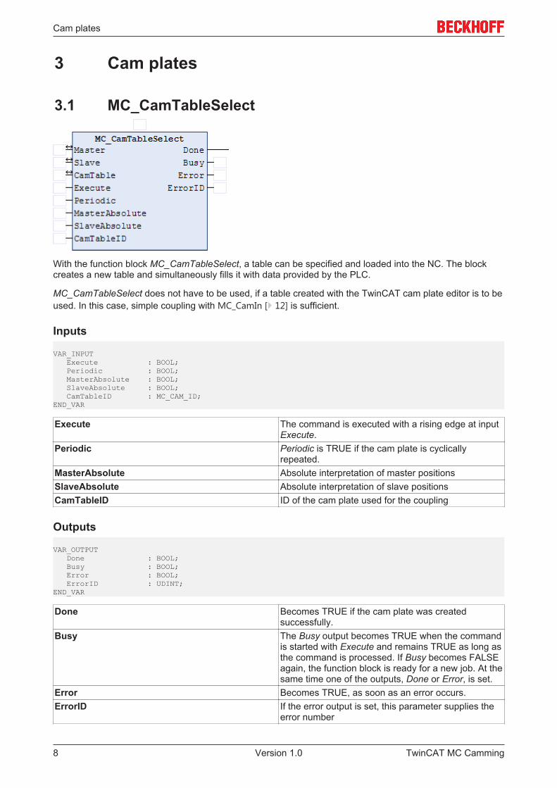
With the function block MC_CamTableSelect, a table can be specified and loaded into the NC. The blockcreates a new table and simultaneously fills it with data provided by the PLC.
MC_CamTableSelect does not have to be used, if a table created with the TwinCAT cam plate editor is to beused. In this case, simple coupling with MC_CamIn [} 12] is sufficient.
Inputs
VAR_INPUT Execute : BOOL; Periodic : BOOL; MasterAbsolute : BOOL; SlaveAbsolute : BOOL; CamTableID : MC_CAM_ID; END_VAR
Execute The command is executed with a rising edge at inputExecute.
Periodic Periodic is TRUE if the cam plate is cyclicallyrepeated.
MasterAbsolute Absolute interpretation of master positionsSlaveAbsolute Absolute interpretation of slave positionsCamTableID ID of the cam plate used for the coupling
Outputs
VAR_OUTPUT Done : BOOL; Busy : BOOL; Error : BOOL; ErrorID : UDINT;END_VAR
Done Becomes TRUE if the cam plate was createdsuccessfully.
Busy The Busy output becomes TRUE when the commandis started with Execute and remains TRUE as long asthe command is processed. If Busy becomes FALSEagain, the function block is ready for a new job. At thesame time one of the outputs, Done or Error, is set.
Error Becomes TRUE, as soon as an error occurs.ErrorID If the error output is set, this parameter supplies the
error number
TwinCAT MC Camming8 Version 1.0
Cam plates
Inputs/outputs
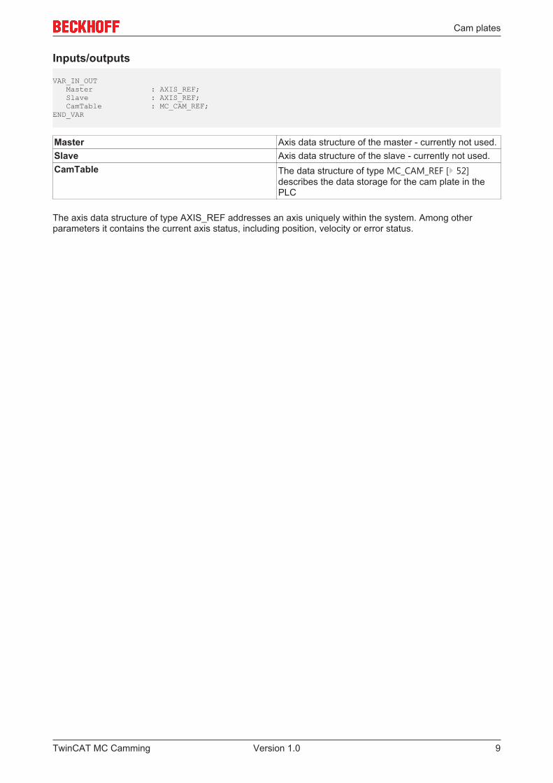
VAR_IN_OUT Master : AXIS_REF; Slave : AXIS_REF; CamTable : MC_CAM_REF;END_VAR
Master Axis data structure of the master - currently not used.Slave Axis data structure of the slave - currently not used.CamTable The data structure of type MC_CAM_REF [} 52]
describes the data storage for the cam plate in thePLC
The axis data structure of type AXIS_REF addresses an axis uniquely within the system. Among otherparameters it contains the current axis status, including position, velocity or error status.
TwinCAT MC Camming 9Version 1.0

Cam plates
3.2 MC_CamOut
The function block MC_CamOut deactivates a master-slave coupling.
Note: If a slave axis is uncoupled during the movement, it is not automatically stopped, but reaches acontinuous velocity with which it will continue to travel endlessly. The axis can be stopped with a Stopcommand.
Attention
Calling during the movementAfter uncoupling, the slave axis switches to acceleration-free state and continues to movewith the resulting constant speed. There is no positioning based on the master travel pathcalculated with the coupling factor. Instead, the behavior matches the behavior after aMC_MoveVelocity command.
Inputs
VAR_INPUT Execute : BOOL; Options : ST_GearOutOptions;END_VAR
Execute The command is executed with a rising edge at inputExecute.
Options Currently not implemented
Outputs
VAR_OUTPUT Done : BOOL; Busy : BOOL; Error : BOOL; ErrorID : UDINT;END_VAR
Done Becomes TRUE, if the axis was successfullyuncoupled.
Busy The Busy output becomes TRUE when the commandis started with Execute and remains TRUE as long asthe command is processed. If Busy becomes FALSEagain, the function block is ready for a new job. At thesame time one of the outputs, Done or Error, is set.
Error Becomes TRUE, as soon as an error occurs.ErrorID If the error output is set, this parameter supplies the
error number
Inputs/outputs
VAR_IN_OUT Slave : AXIS_REF;END_VAR
TwinCAT MC Camming10 Version 1.0

Cam plates
Slave Axis data structure of the Slave.
The axis data structure of type AXIS_REF addresses an axis uniquely within the system. Among otherparameters it contains the current axis status, including position, velocity or error status.
TwinCAT MC Camming 11Version 1.0
Cam plates
3.3 MC_CamIn
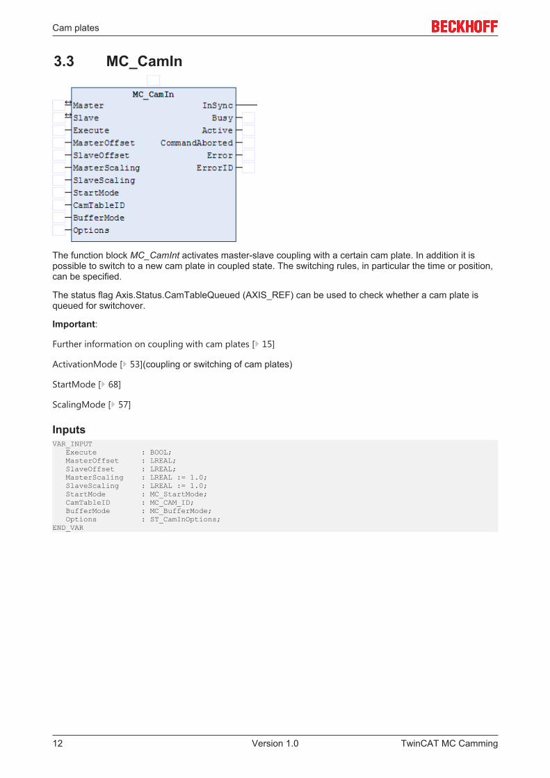
The function block MC_CamInt activates master-slave coupling with a certain cam plate. In addition it ispossible to switch to a new cam plate in coupled state. The switching rules, in particular the time or position,can be specified.
The status flag Axis.Status.CamTableQueued (AXIS_REF) can be used to check whether a cam plate isqueued for switchover.
Important:
Further information on coupling with cam plates [} 15]
ActivationMode [} 53](coupling or switching of cam plates)
StartMode [} 68]
ScalingMode [} 57]
InputsVAR_INPUT Execute : BOOL; MasterOffset : LREAL; SlaveOffset : LREAL; MasterScaling : LREAL := 1.0; SlaveScaling : LREAL := 1.0; StartMode : MC_StartMode; CamTableID : MC_CAM_ID; BufferMode : MC_BufferMode; Options : ST_CamInOptions;END_VAR
TwinCAT MC Camming12 Version 1.0
Cam plates
Execute The command is executed with a rising edge at input Execute.MasterOffset Offset to the master position of the cam plateSlaveOffset Offset to the slave position of the cam plateMasterScaling Scaling of the master position of the cam plateSlaveScaling Scaling of the slave position of the cam plateStartMode StartMode [} 68] determines whether the cam plate position is interpreted
absolute or relative to the coupling position.StartMode can be relative or absolute for master (X coordinate) and slave (Ycoordinate).
CamTableID ID [} 51] of the cam plate used for the couplingBufferMode Currently not implementedOptions Data structure [} 69] with further coupling and switching options:
ActivationMode The ActivationMode [} 53] is used to specify thetime and/or position at which the cam plate couplingor switchover is to take place.ActivationMode can also be specified when a slave iscoupled for the first time.
ActivationPosition Optional master position at which a cam plate isswitched, depending on the ActivationMode.(not required for first coupling.)If ActivationModeMC_CAMACTIVATION_ATMASTERCAMPOS isused, the position refers to the non-scaled cam plate.If the position in the application refers to the scaledcam plate, it can be divided by the MasterScalingbefore the function block is called.
MasterScalingMode optional Scaling mode [} 57] for the master positionof the cam plate
SlaveScalingMode optional Scaling mode [} 57] for the slave position ofthe cam plate
Interpolation type Interpolation type [} 61] for position tables. Notrequired for motion functions.
OutputsVAR_OUTPUT InSync : BOOL; Busy : BOOL; Active : BOOL; CommandAborted : BOOL; Error : BOOL; ErrorID : UDINT;END_VAR
InSync Becomes TRUE, if the coupling was successful and the cam plate is active.Busy The Busy output becomes TRUE when the command is started with Execute
and remains TRUE as long as the command is processed. If Busy becomesFALSE again, the function block is ready for a new job. At the same time one ofthe outputs InSync, CommandAborted or Error is set.
Active Active indicates that the command is executed For cam plate switching Activebecomes TRUE, if the coupling command was executed successfully but thecam plate is still queued. If the cam plate is activated depending on theActivationMode, Active becomes FALSE and InSync is set.
CommandAborted Becomes TRUE, if the command could not be fully executed. The axis may havebecome decoupled during the coupling process (simultaneous commandexecution).
Error Becomes TRUE, as soon as an error occurs.ErrorID If the error output is set, this parameter supplies the error number
TwinCAT MC Camming 13Version 1.0
Cam plates
Inputs/outputsVAR_IN_OUT Master : AXIS_REF; Slave : AXIS_REF;END_VAR
Master Master axis data structure.Slave Axis data structure of the Slave.
The axis data structure of type AXIS_REF addresses an axis uniquely within the system. Among otherparameters it contains the current axis status, including position, velocity or error status.
TwinCAT MC Camming14 Version 1.0
Cam plates
3.4 MC_CaminAppendix
Coupling with cam plates
The function block MC_CamIn [} 12] can be used to establish a cam plate coupling (or table coupling)between a master axis and a slave axis. Note that prior to the coupling the slave axis has to be at a positiondefined by the cam plate. After the coupling and once the master has been started, the slave position iscalculated directly from the cam plate. The slave axis is therefore not slowly synchronized with the cam plate,but it will jump if it is not already at the table position.
In practice the question arises what position the slave should be in prior to the coupling, and how this iscalculated. The following figures illustrate the procedure.
Notes: For all subsequent calculations only axis set positions are used. The actual positions are not used inthe calculations, since they would lead to calculation errors, particularly with cyclic cam plates.
Only absolute table couplings are considered. For relative couplings, the coupling position of the master orslave axis is considered in the calculations as an additional offset.
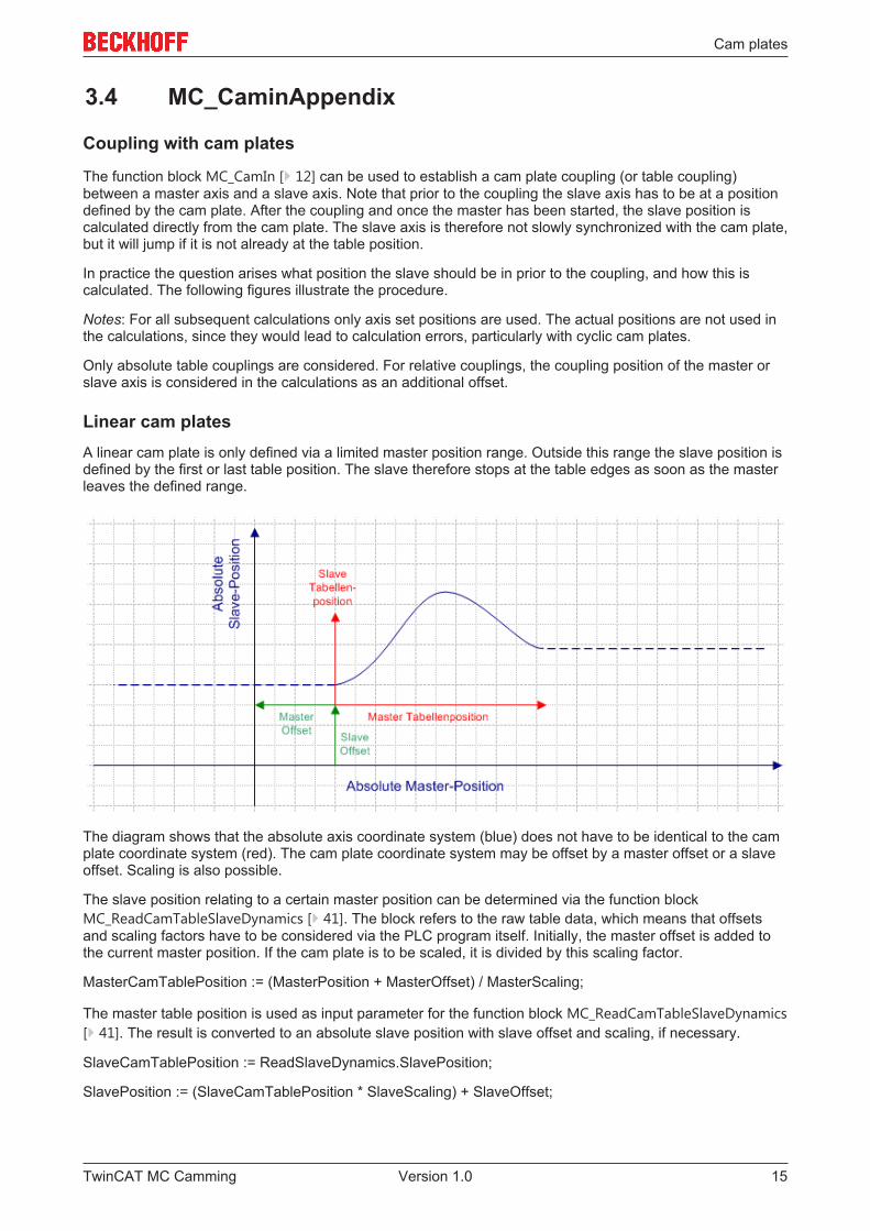
Linear cam platesA linear cam plate is only defined via a limited master position range. Outside this range the slave position isdefined by the first or last table position. The slave therefore stops at the table edges as soon as the masterleaves the defined range.
The diagram shows that the absolute axis coordinate system (blue) does not have to be identical to the camplate coordinate system (red). The cam plate coordinate system may be offset by a master offset or a slaveoffset. Scaling is also possible.
The slave position relating to a certain master position can be determined via the function blockMC_ReadCamTableSlaveDynamics [} 41]. The block refers to the raw table data, which means that offsetsand scaling factors have to be considered via the PLC program itself. Initially, the master offset is added tothe current master position. If the cam plate is to be scaled, it is divided by this scaling factor.
MasterCamTablePosition := (MasterPosition + MasterOffset) / MasterScaling;
The master table position is used as input parameter for the function block MC_ReadCamTableSlaveDynamics[} 41]. The result is converted to an absolute slave position with slave offset and scaling, if necessary.
SlaveCamTablePosition := ReadSlaveDynamics.SlavePosition;
SlavePosition := (SlaveCamTablePosition * SlaveScaling) + SlaveOffset;
TwinCAT MC Camming 15Version 1.0
Cam plates
The slave is moved to this position prior to the coupling. Alternatively, the master may be moved to a positionthat corresponds to the current slave position. However, generally this position cannot be determined fromthe cam plate, since the cam plate may be ambiguous.
Notice: Since the master offset is added in the first formula, a positive offset leads to the cam platecoordinate system being shifted to the left in negative direction. Accordingly, the master offset in the diagramis negative. A positive slave offset leads to the cam plate coordinate system being shifted upwards inpositive direction.
Cyclic cam plates without liftA cyclic cam plate without lift is characterized by the fact that the slave start and end positions in the tableare identical. The slave therefore moves cyclically within a defined range, without changing its positionpermanently in a particular direction.
For these cam plate types, master/slave coupling requires the same preparation as for a linear cam plate.The starting position of the slave can therefore be calculated as described above. It is not necessary to usethe modulo position of the master for the calculation, since the absolute position is already correctly takeninto account via the coupling command.
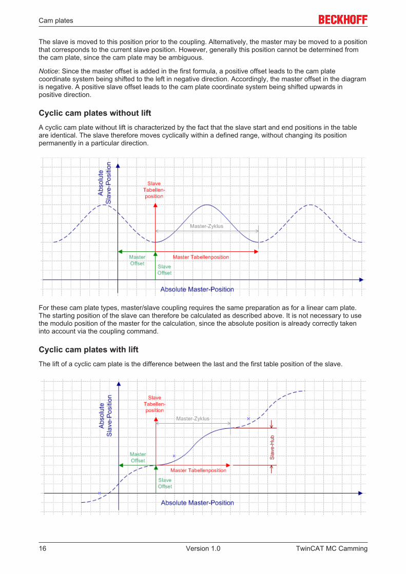
Cyclic cam plates with liftThe lift of a cyclic cam plate is the difference between the last and the first table position of the slave.
TwinCAT MC Camming16 Version 1.0
Cam plates
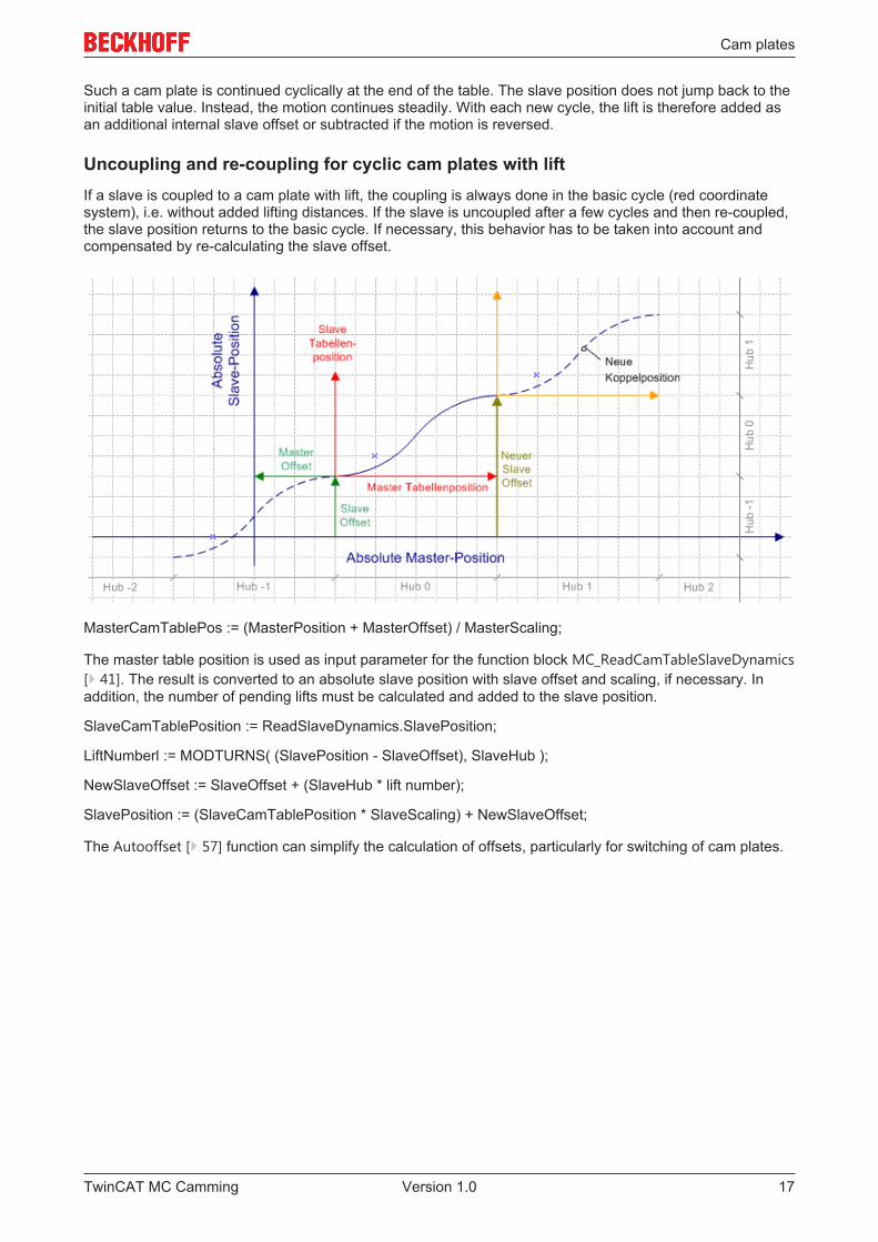
Such a cam plate is continued cyclically at the end of the table. The slave position does not jump back to theinitial table value. Instead, the motion continues steadily. With each new cycle, the lift is therefore added asan additional internal slave offset or subtracted if the motion is reversed.
Uncoupling and re-coupling for cyclic cam plates with liftIf a slave is coupled to a cam plate with lift, the coupling is always done in the basic cycle (red coordinatesystem), i.e. without added lifting distances. If the slave is uncoupled after a few cycles and then re-coupled,the slave position returns to the basic cycle. If necessary, this behavior has to be taken into account andcompensated by re-calculating the slave offset.
MasterCamTablePos := (MasterPosition + MasterOffset) / MasterScaling;
The master table position is used as input parameter for the function block MC_ReadCamTableSlaveDynamics[} 41]. The result is converted to an absolute slave position with slave offset and scaling, if necessary. Inaddition, the number of pending lifts must be calculated and added to the slave position.
SlaveCamTablePosition := ReadSlaveDynamics.SlavePosition;
LiftNumberl := MODTURNS( (SlavePosition - SlaveOffset), SlaveHub );
NewSlaveOffset := SlaveOffset + (SlaveHub * lift number);
SlavePosition := (SlaveCamTablePosition * SlaveScaling) + NewSlaveOffset;
The Autooffset [} 57] function can simplify the calculation of offsets, particularly for switching of cam plates.
TwinCAT MC Camming 17Version 1.0
Cam plates
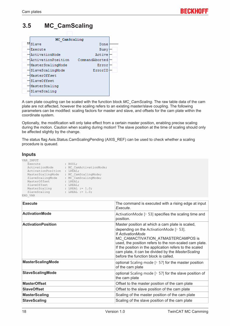
3.5 MC_CamScaling
A cam plate coupling can be scaled with the function block MC_CamScaling. The raw table data of the camplate are not affected, however the scaling refers to an existing master/slave coupling. The followingparameters can be modified: scaling factors for master and slave, and offsets for the cam plate within thecoordinate system.
Optionally, the modification will only take effect from a certain master position, enabling precise scalingduring the motion. Caution when scaling during motion! The slave position at the time of scaling should onlybe affected slightly by the change.
The status flag Axis.Status.CamScalingPending (AXIS_REF) can be used to check whether a scalingprocedure is queued.
InputsVAR_INPUT Execute : BOOL; ActivationMode : MC_CamActivationMode; ActivationPosition : LREAL; MasterScalingMode : MC_CamScalingMode; SlaveScalingMode : MC_CamScalingMode; MasterOffset : LREAL; SlaveOffset : LREAL; MasterScaling : LREAL := 1.0; SlaveScaling : LREAL := 1.0;END_VAR
Execute The command is executed with a rising edge at inputExecute.
ActivationMode ActivationMode [} 53] specifies the scaling time andposition.
ActivationPosition Master position at which a cam plate is scaled,depending on the ActivationMode [} 53].If ActivationModeMC_CAMACTIVATION_ATMASTERCAMPOS isused, the position refers to the non-scaled cam plate.If the position in the application refers to the scaledcam plate, it can be divided by the MasterScalingbefore the function block is called.
MasterScalingMode optional Scaling mode [} 57] for the master positionof the cam plate
SlaveScalingMode optional Scaling mode [} 57] for the slave position ofthe cam plate
MasterOffset Offset to the master position of the cam plateSlaveOffset Offset to the slave position of the cam plateMasterScaling Scaling of the master position of the cam plateSlaveScaling Scaling of the slave position of the cam plate
TwinCAT MC Camming18 Version 1.0
Cam plates
OutputsVAR_OUTPUT Done : BOOL; Busy : BOOL; Active : BOOL; CommandAborted : BOOL; Error : BOOL; ErrorID : UDINT;END_VAR
Done Becomes TRUE if scaling was successful.Busy The Busy output becomes TRUE when the command
is started with Execute and remains TRUE as long asthe command is processed. If Busy becomes FALSEagain, the function block is ready for a new job. At thesame time one of the outputs, Done,CommandAborted or Error, is set.
Active Active indicates that the command is executed Whenthe scaling was done depending on ActivationMode,Active becomes FALSE and Done is set.
CommandAborted Becomes TRUE, if the command could not be fullyexecuted.
Error Becomes TRUE, as soon as an error occurs.ErrorID If the error output is set, this parameter supplies the
error number
Inputs/outputsVAR_IN_OUT Slave : AXIS_REF;END_VAR
Slave Axis data structure of the Slave.
The axis data structure of type AXIS_REF addresses an axis uniquely within the system. Among otherparameters it contains the current axis status, including position, velocity or error status.
TwinCAT MC Camming 19Version 1.0
Multi cam plates
4 Multi cam plates
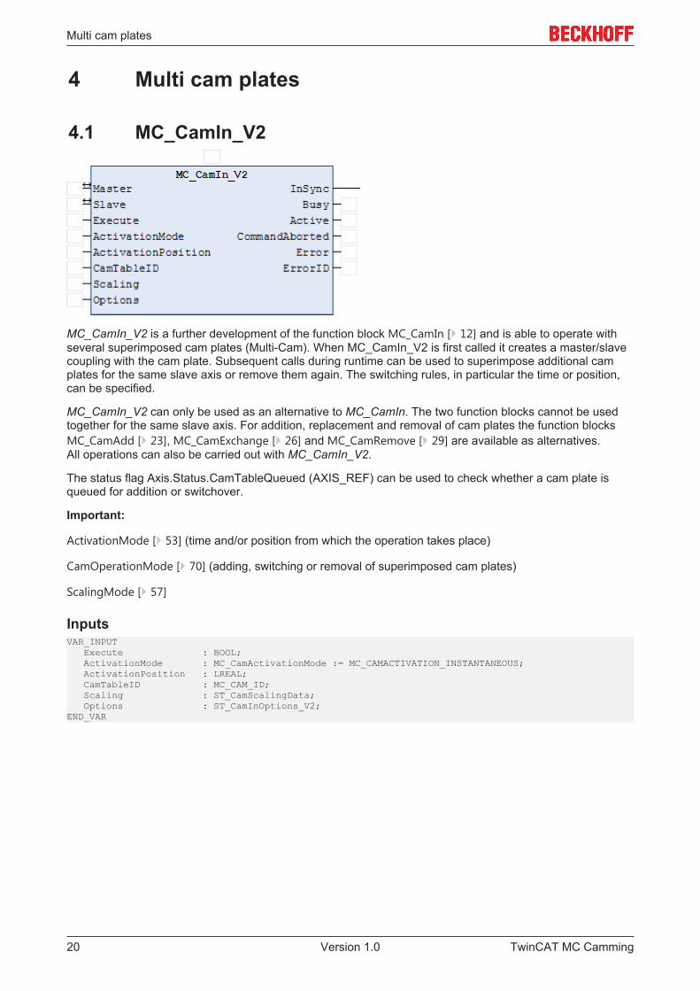
4.1 MC_CamIn_V2
MC_CamIn_V2 is a further development of the function block MC_CamIn [} 12] and is able to operate withseveral superimposed cam plates (Multi-Cam). When MC_CamIn_V2 is first called it creates a master/slavecoupling with the cam plate. Subsequent calls during runtime can be used to superimpose additional camplates for the same slave axis or remove them again. The switching rules, in particular the time or position,can be specified.
MC_CamIn_V2 can only be used as an alternative to MC_CamIn. The two function blocks cannot be usedtogether for the same slave axis. For addition, replacement and removal of cam plates the function blocksMC_CamAdd [} 23], MC_CamExchange [} 26] and MC_CamRemove [} 29] are available as alternatives.All operations can also be carried out with MC_CamIn_V2.
The status flag Axis.Status.CamTableQueued (AXIS_REF) can be used to check whether a cam plate isqueued for addition or switchover.
Important:
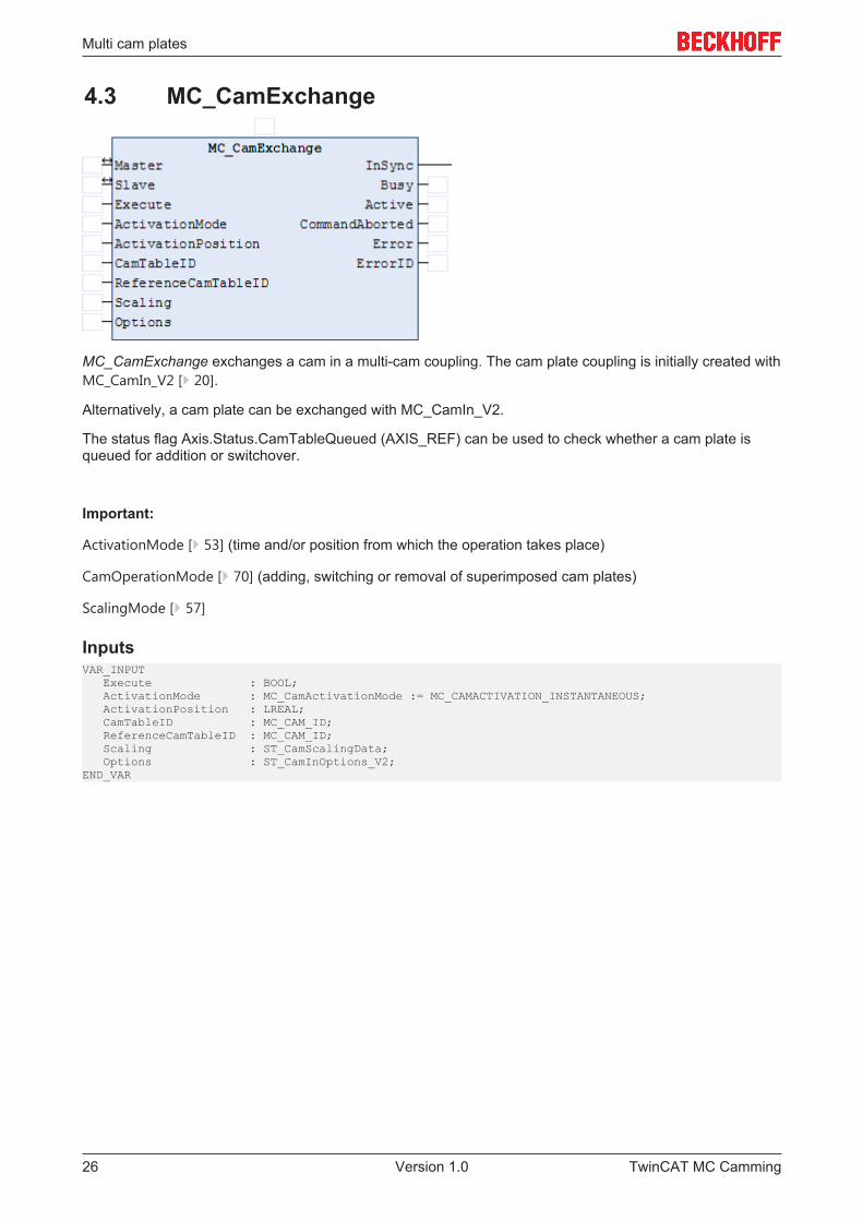
ActivationMode [} 53] (time and/or position from which the operation takes place)
CamOperationMode [} 70] (adding, switching or removal of superimposed cam plates)
ScalingMode [} 57]
InputsVAR_INPUT Execute : BOOL; ActivationMode : MC_CamActivationMode := MC_CAMACTIVATION_INSTANTANEOUS; ActivationPosition : LREAL; CamTableID : MC_CAM_ID; Scaling : ST_CamScalingData; Options : ST_CamInOptions_V2;END_VAR
TwinCAT MC Camming20 Version 1.0
Multi cam plates
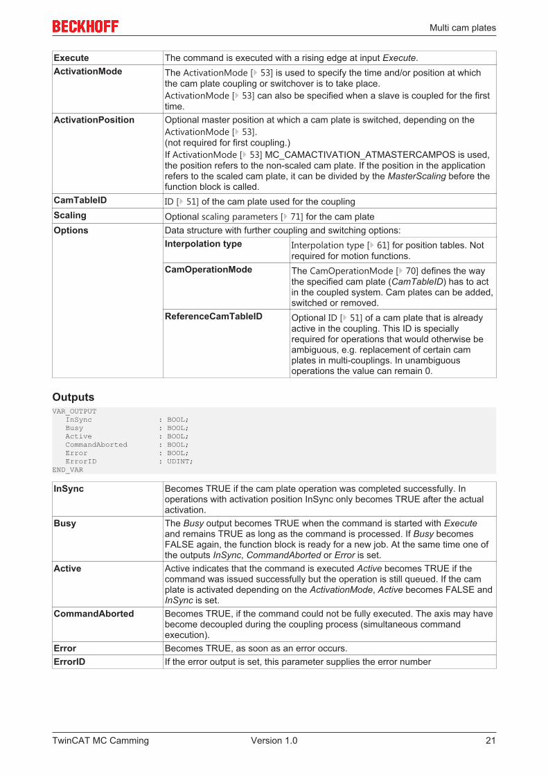
Execute The command is executed with a rising edge at input Execute.ActivationMode The ActivationMode [} 53] is used to specify the time and/or position at which
the cam plate coupling or switchover is to take place.ActivationMode [} 53] can also be specified when a slave is coupled for the firsttime.
ActivationPosition Optional master position at which a cam plate is switched, depending on theActivationMode [} 53].(not required for first coupling.)If ActivationMode [} 53] MC_CAMACTIVATION_ATMASTERCAMPOS is used,the position refers to the non-scaled cam plate. If the position in the applicationrefers to the scaled cam plate, it can be divided by the MasterScaling before thefunction block is called.
CamTableID ID [} 51] of the cam plate used for the couplingScaling Optional scaling parameters [} 71] for the cam plateOptions Data structure with further coupling and switching options:
Interpolation type Interpolation type [} 61] for position tables. Notrequired for motion functions.
CamOperationMode The CamOperationMode [} 70] defines the waythe specified cam plate (CamTableID) has to actin the coupled system. Cam plates can be added,switched or removed.
ReferenceCamTableID Optional ID [} 51] of a cam plate that is alreadyactive in the coupling. This ID is speciallyrequired for operations that would otherwise beambiguous, e.g. replacement of certain camplates in multi-couplings. In unambiguousoperations the value can remain 0.
OutputsVAR_OUTPUT InSync : BOOL; Busy : BOOL; Active : BOOL; CommandAborted : BOOL; Error : BOOL; ErrorID : UDINT;END_VAR
InSync Becomes TRUE if the cam plate operation was completed successfully. Inoperations with activation position InSync only becomes TRUE after the actualactivation.
Busy The Busy output becomes TRUE when the command is started with Executeand remains TRUE as long as the command is processed. If Busy becomesFALSE again, the function block is ready for a new job. At the same time one ofthe outputs InSync, CommandAborted or Error is set.
Active Active indicates that the command is executed Active becomes TRUE if thecommand was issued successfully but the operation is still queued. If the camplate is activated depending on the ActivationMode, Active becomes FALSE andInSync is set.
CommandAborted Becomes TRUE, if the command could not be fully executed. The axis may havebecome decoupled during the coupling process (simultaneous commandexecution).
Error Becomes TRUE, as soon as an error occurs.ErrorID If the error output is set, this parameter supplies the error number
TwinCAT MC Camming 21Version 1.0
Multi cam plates
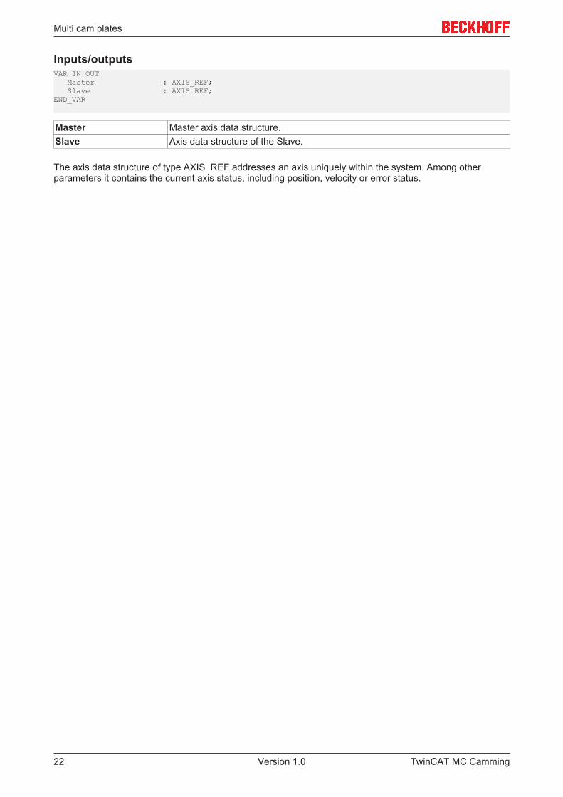
Inputs/outputsVAR_IN_OUT Master : AXIS_REF; Slave : AXIS_REF;END_VAR
Master Master axis data structure.Slave Axis data structure of the Slave.
The axis data structure of type AXIS_REF addresses an axis uniquely within the system. Among otherparameters it contains the current axis status, including position, velocity or error status.
TwinCAT MC Camming22 Version 1.0

Multi cam plates
4.2 MC_CamAdd
MC_CamAdd adds a cam plate to a multi-cam coupling. The cam plate coupling is initially created withMC_CamIn_V2 [} 20].
Alternatively, a cam plate can be added with MC_CamIn_V2.
The status flag Axis.Status.CamTableQueued (AXIS_REF) can be used to check whether a cam plate isqueued for addition or switchover.
Important: ActivationMode [} 53] (time and/or position from which the operation takes place)
CamOperationMode [} 70] (adding, switching or removal of superimposed cam plates)
ScalingMode [} 57]
InputsVAR_INPUT Execute : BOOL; ActivationMode : MC_CamActivationMode := MC_CAMACTIVATION_INSTANTANEOUS; ActivationPosition : LREAL; CamTableID : MC_CAM_ID; Scaling : ST_CamScalingData; Options : ST_CamInOptions_V2;END_VAR
TwinCAT MC Camming 23Version 1.0
Multi cam plates
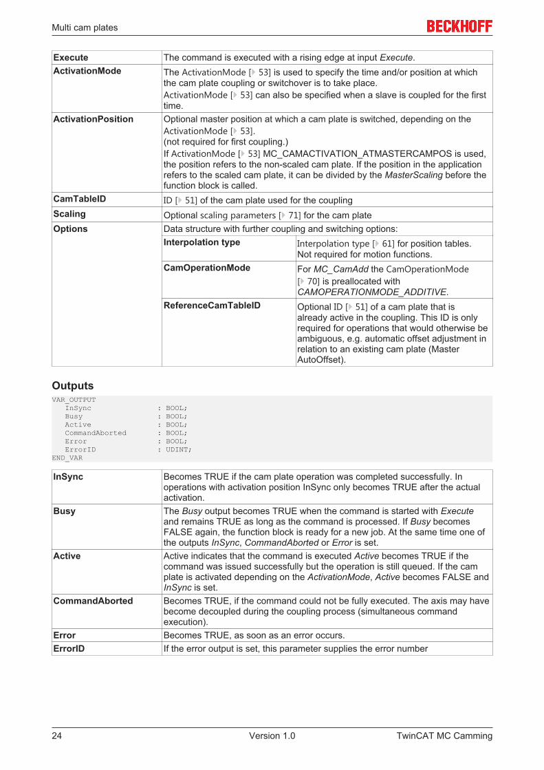
Execute The command is executed with a rising edge at input Execute.ActivationMode The ActivationMode [} 53] is used to specify the time and/or position at which
the cam plate coupling or switchover is to take place.ActivationMode [} 53] can also be specified when a slave is coupled for the firsttime.
ActivationPosition Optional master position at which a cam plate is switched, depending on theActivationMode [} 53].(not required for first coupling.)If ActivationMode [} 53] MC_CAMACTIVATION_ATMASTERCAMPOS is used,the position refers to the non-scaled cam plate. If the position in the applicationrefers to the scaled cam plate, it can be divided by the MasterScaling before thefunction block is called.
CamTableID ID [} 51] of the cam plate used for the couplingScaling Optional scaling parameters [} 71] for the cam plateOptions Data structure with further coupling and switching options:
Interpolation type Interpolation type [} 61] for position tables.Not required for motion functions.
CamOperationMode For MC_CamAdd the CamOperationMode[} 70] is preallocated withCAMOPERATIONMODE_ADDITIVE.
ReferenceCamTableID Optional ID [} 51] of a cam plate that isalready active in the coupling. This ID is onlyrequired for operations that would otherwise beambiguous, e.g. automatic offset adjustment inrelation to an existing cam plate (MasterAutoOffset).
OutputsVAR_OUTPUT InSync : BOOL; Busy : BOOL; Active : BOOL; CommandAborted : BOOL; Error : BOOL; ErrorID : UDINT;END_VAR
InSync Becomes TRUE if the cam plate operation was completed successfully. Inoperations with activation position InSync only becomes TRUE after the actualactivation.
Busy The Busy output becomes TRUE when the command is started with Executeand remains TRUE as long as the command is processed. If Busy becomesFALSE again, the function block is ready for a new job. At the same time one ofthe outputs InSync, CommandAborted or Error is set.
Active Active indicates that the command is executed Active becomes TRUE if thecommand was issued successfully but the operation is still queued. If the camplate is activated depending on the ActivationMode, Active becomes FALSE andInSync is set.
CommandAborted Becomes TRUE, if the command could not be fully executed. The axis may havebecome decoupled during the coupling process (simultaneous commandexecution).
Error Becomes TRUE, as soon as an error occurs.ErrorID If the error output is set, this parameter supplies the error number
TwinCAT MC Camming24 Version 1.0
Multi cam plates
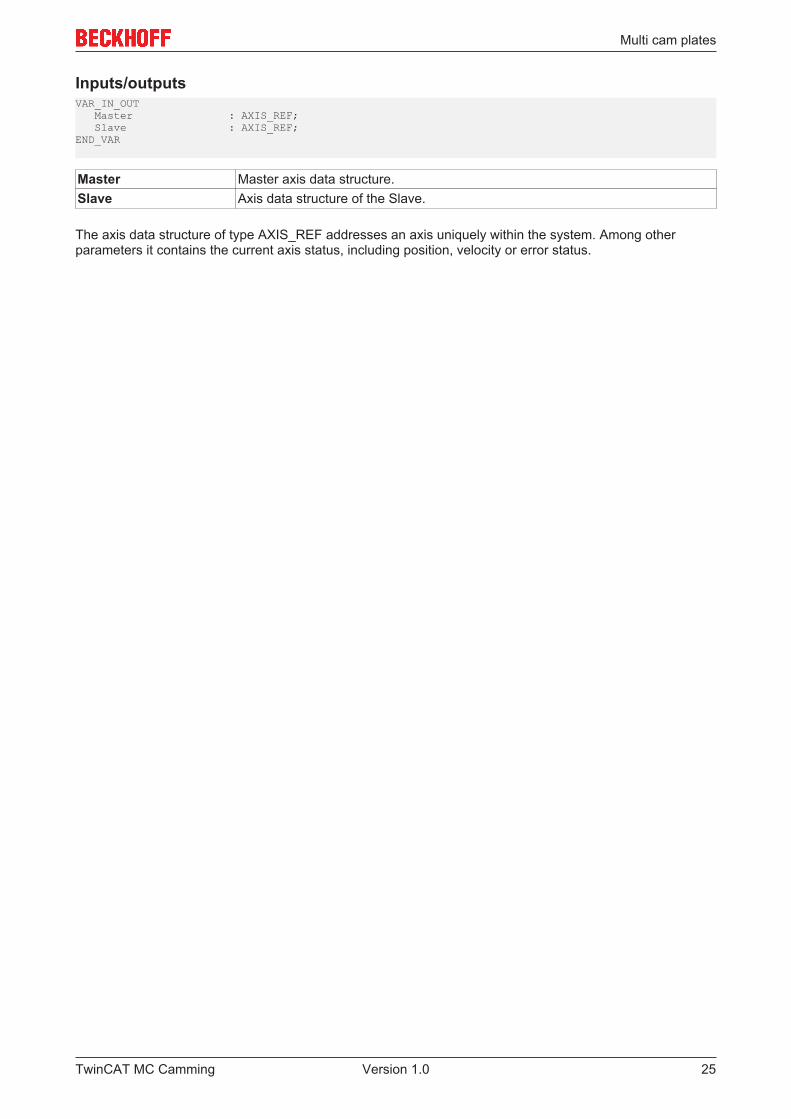
Inputs/outputsVAR_IN_OUT Master : AXIS_REF; Slave : AXIS_REF;END_VAR
Master Master axis data structure.Slave Axis data structure of the Slave.
The axis data structure of type AXIS_REF addresses an axis uniquely within the system. Among otherparameters it contains the current axis status, including position, velocity or error status.
TwinCAT MC Camming 25Version 1.0
Multi cam plates
4.3 MC_CamExchange
MC_CamExchange exchanges a cam in a multi-cam coupling. The cam plate coupling is initially created withMC_CamIn_V2 [} 20].
Alternatively, a cam plate can be exchanged with MC_CamIn_V2.
The status flag Axis.Status.CamTableQueued (AXIS_REF) can be used to check whether a cam plate isqueued for addition or switchover.
Important:
ActivationMode [} 53] (time and/or position from which the operation takes place)
CamOperationMode [} 70] (adding, switching or removal of superimposed cam plates)
ScalingMode [} 57]
InputsVAR_INPUT Execute : BOOL; ActivationMode : MC_CamActivationMode := MC_CAMACTIVATION_INSTANTANEOUS; ActivationPosition : LREAL; CamTableID : MC_CAM_ID; ReferenceCamTableID : MC_CAM_ID; Scaling : ST_CamScalingData; Options : ST_CamInOptions_V2;END_VAR
TwinCAT MC Camming26 Version 1.0
Multi cam plates
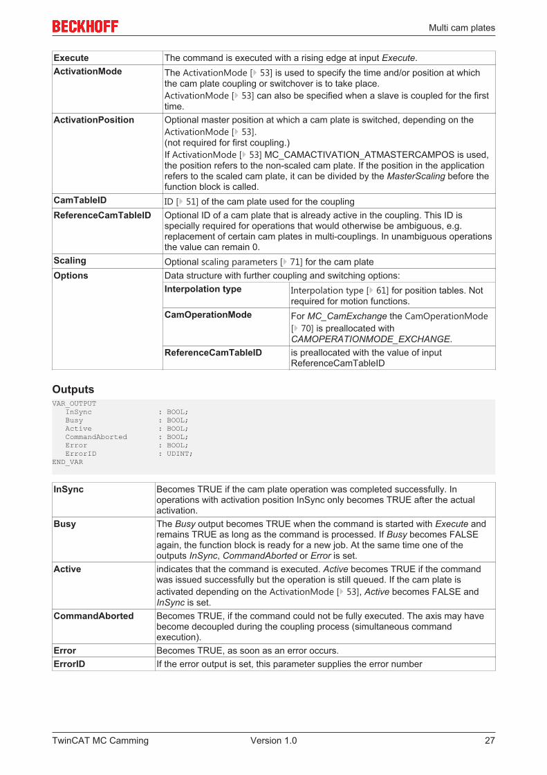
Execute The command is executed with a rising edge at input Execute.ActivationMode The ActivationMode [} 53] is used to specify the time and/or position at which
the cam plate coupling or switchover is to take place.ActivationMode [} 53] can also be specified when a slave is coupled for the firsttime.
ActivationPosition Optional master position at which a cam plate is switched, depending on theActivationMode [} 53].(not required for first coupling.)If ActivationMode [} 53] MC_CAMACTIVATION_ATMASTERCAMPOS is used,the position refers to the non-scaled cam plate. If the position in the applicationrefers to the scaled cam plate, it can be divided by the MasterScaling before thefunction block is called.
CamTableID ID [} 51] of the cam plate used for the couplingReferenceCamTableID Optional ID of a cam plate that is already active in the coupling. This ID is
specially required for operations that would otherwise be ambiguous, e.g.replacement of certain cam plates in multi-couplings. In unambiguous operationsthe value can remain 0.
Scaling Optional scaling parameters [} 71] for the cam plateOptions Data structure with further coupling and switching options:
Interpolation type Interpolation type [} 61] for position tables. Notrequired for motion functions.
CamOperationMode For MC_CamExchange the CamOperationMode[} 70] is preallocated withCAMOPERATIONMODE_EXCHANGE.
ReferenceCamTableID is preallocated with the value of inputReferenceCamTableID
OutputsVAR_OUTPUT InSync : BOOL; Busy : BOOL; Active : BOOL; CommandAborted : BOOL; Error : BOOL; ErrorID : UDINT;END_VAR
InSync Becomes TRUE if the cam plate operation was completed successfully. Inoperations with activation position InSync only becomes TRUE after the actualactivation.
Busy The Busy output becomes TRUE when the command is started with Execute andremains TRUE as long as the command is processed. If Busy becomes FALSEagain, the function block is ready for a new job. At the same time one of theoutputs InSync, CommandAborted or Error is set.
Active indicates that the command is executed. Active becomes TRUE if the commandwas issued successfully but the operation is still queued. If the cam plate isactivated depending on the ActivationMode [} 53], Active becomes FALSE andInSync is set.
CommandAborted Becomes TRUE, if the command could not be fully executed. The axis may havebecome decoupled during the coupling process (simultaneous commandexecution).
Error Becomes TRUE, as soon as an error occurs.ErrorID If the error output is set, this parameter supplies the error number
TwinCAT MC Camming 27Version 1.0
Multi cam plates
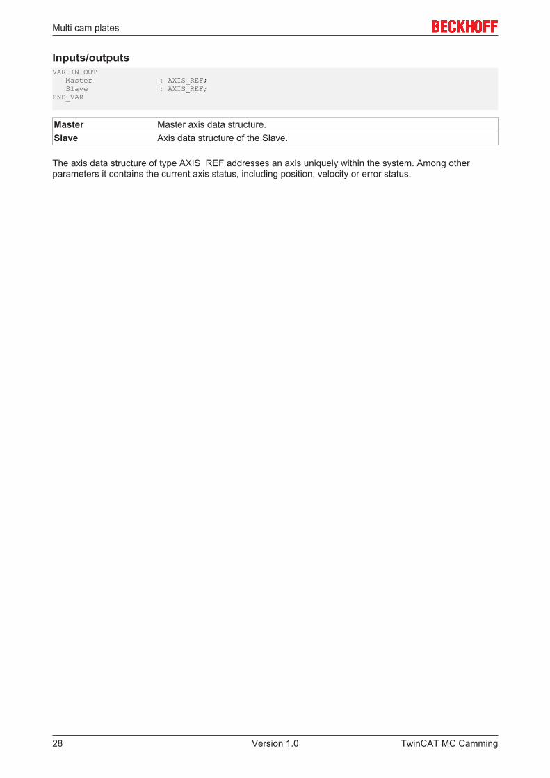
Inputs/outputsVAR_IN_OUT Master : AXIS_REF; Slave : AXIS_REF;END_VAR
Master Master axis data structure.Slave Axis data structure of the Slave.
The axis data structure of type AXIS_REF addresses an axis uniquely within the system. Among otherparameters it contains the current axis status, including position, velocity or error status.
TwinCAT MC Camming28 Version 1.0
Multi cam plates
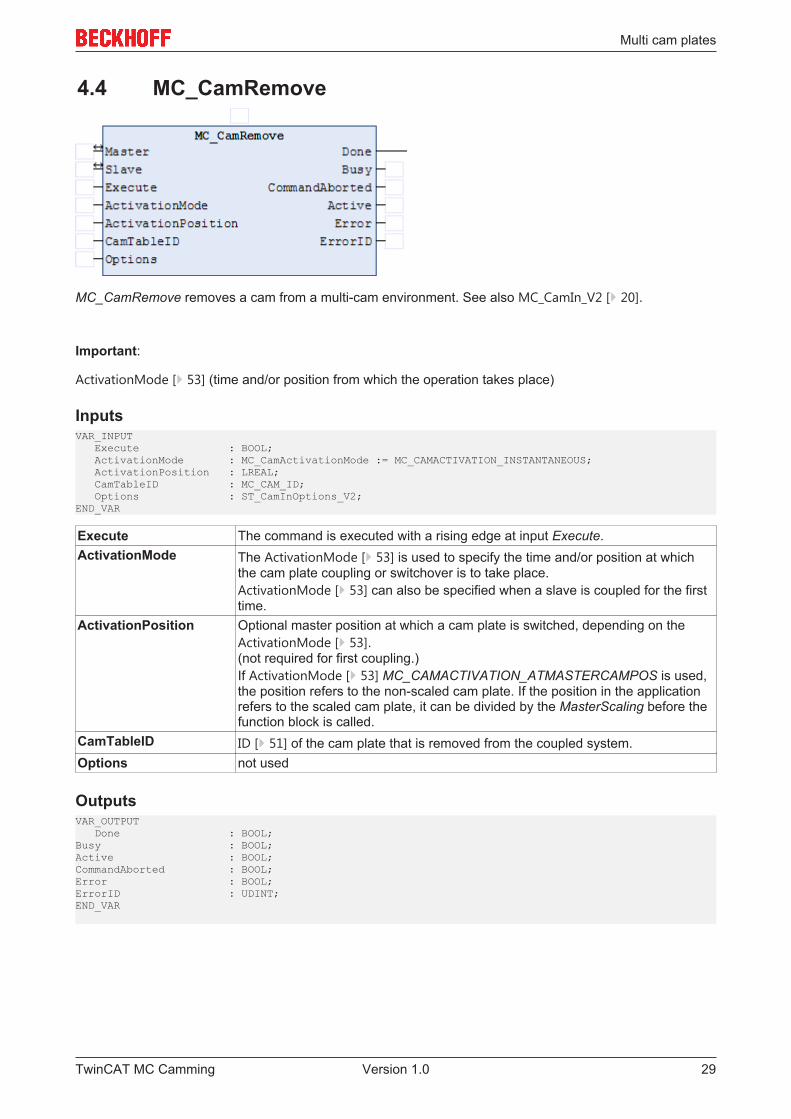
4.4 MC_CamRemove
MC_CamRemove removes a cam from a multi-cam environment. See also MC_CamIn_V2 [} 20].
Important:
ActivationMode [} 53] (time and/or position from which the operation takes place)
InputsVAR_INPUT Execute : BOOL; ActivationMode : MC_CamActivationMode := MC_CAMACTIVATION_INSTANTANEOUS; ActivationPosition : LREAL; CamTableID : MC_CAM_ID; Options : ST_CamInOptions_V2;END_VAR
Execute The command is executed with a rising edge at input Execute.ActivationMode The ActivationMode [} 53] is used to specify the time and/or position at which
the cam plate coupling or switchover is to take place.ActivationMode [} 53] can also be specified when a slave is coupled for the firsttime.
ActivationPosition Optional master position at which a cam plate is switched, depending on theActivationMode [} 53].(not required for first coupling.)If ActivationMode [} 53] MC_CAMACTIVATION_ATMASTERCAMPOS is used,the position refers to the non-scaled cam plate. If the position in the applicationrefers to the scaled cam plate, it can be divided by the MasterScaling before thefunction block is called.
CamTableID ID [} 51] of the cam plate that is removed from the coupled system.Options not used
OutputsVAR_OUTPUT Done : BOOL;Busy : BOOL; Active : BOOL; CommandAborted : BOOL;Error : BOOL;ErrorID : UDINT;END_VAR
TwinCAT MC Camming 29Version 1.0
Multi cam plates
Done Becomes TRUE if the cam plate operation was completed successfully. Inoperations with activation position Done only becomes TRUE after the actualdeactivation.
Busy The Busy output becomes TRUE when the command is started with Executeand remains TRUE as long as the command is processed. If Busy becomesFALSE again, the function block is ready for a new job. At the same time one ofthe outputs InSync, CommandAborted or Error is set.
Active Active indicates that the command is executed Active becomes TRUE if thecommand was issued successfully but the operation is still queued. If the camplate is activated depending on the ActivationMode [} 53], Active becomesFALSE and InSync is set.
CommandAborted Becomes TRUE, if the command could not be fully executed. The axis may havebecome decoupled during the coupling process (simultaneous commandexecution).
Error Becomes TRUE, as soon as an error occurs.ErrorID If the error output is set, this parameter supplies the error number
Inputs/outputsVAR_IN_OUT Master : AXIS_REF; Slave : AXIS_REF;END_VAR
Master Master axis data structure.Slave Axis data structure of the Slave.
The axis data structure of type AXIS_REF addresses an axis uniquely within the system. Among otherparameters it contains the current axis status, including position, velocity or error status.
TwinCAT MC Camming30 Version 1.0
Multi cam plates
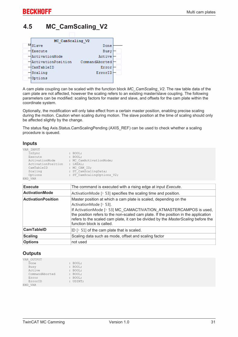
4.5 MC_CamScaling_V2
A cam plate coupling can be scaled with the function block MC_CamScaling_V2. The raw table data of thecam plate are not affected, however the scaling refers to an existing master/slave coupling. The followingparameters can be modified: scaling factors for master and slave, and offsets for the cam plate within thecoordinate system.
Optionally, the modification will only take effect from a certain master position, enabling precise scalingduring the motion. Caution when scaling during motion. The slave position at the time of scaling should onlybe affected slightly by the change.
The status flag Axis.Status.CamScalingPending (AXIS_REF) can be used to check whether a scalingprocedure is queued.
InputsVAR_INPUT InSync : BOOL; Execute : BOOL; ActivationMode : MC_CamActivationMode; ActivationPosition : LREAL; CamTableID : MC_CAM_ID; Scaling : ST_CamScalingData; Options : ST_CamScalingOptions_V2;END_VAR
Execute The command is executed with a rising edge at input Execute.ActivationMode ActivationMode [} 53] specifies the scaling time and position.ActivationPosition Master position at which a cam plate is scaled, depending on the
ActivationMode [} 53].If ActivationMode [} 53] MC_CAMACTIVATION_ATMASTERCAMPOS is used,the position refers to the non-scaled cam plate. If the position in the applicationrefers to the scaled cam plate, it can be divided by the MasterScaling before thefunction block is called.
CamTableID ID [} 51] of the cam plate that is scaled.Scaling Scaling data such as mode, offset and scaling factorOptions not used
OutputsVAR_OUTPUT Done : BOOL; Busy : BOOL; Active : BOOL; CommandAborted : BOOL; Error : BOOL; ErrorID : UDINT;END_VAR
TwinCAT MC Camming 31Version 1.0
Multi cam plates
Done Becomes TRUE if scaling was successful.Busy The Busy output becomes TRUE when the command is started with Execute
and remains TRUE as long as the command is processed. If Busy becomesFALSE again, the function block is ready for a new job. At the same time one ofthe outputs, Done, CommandAborted or Error, is set.
Active Active indicates that the command is executed When the scaling was donedepending on ActivationMode [} 53], Active becomes FALSE and Done is set.
CommandAborted Becomes TRUE, if the command could not be fully executed.Error Becomes TRUE, as soon as an error occurs.ErrorID If the error output is set, this parameter supplies the error number
Inputs/outputsVAR_IN_OUT Slave : AXIS_REF;END_VAR
Slave Axis data structure of the Slave.
The axis data structure of type AXIS_REF addresses an axis uniquely within the system. Among otherparameters it contains the current axis status, including position, velocity or error status.
TwinCAT MC Camming32 Version 1.0
Motion functions
5 Motion functions
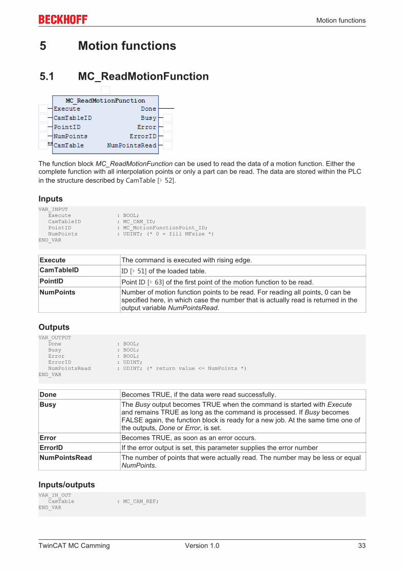
5.1 MC_ReadMotionFunction
The function block MC_ReadMotionFunction can be used to read the data of a motion function. Either thecomplete function with all interpolation points or only a part can be read. The data are stored within the PLCin the structure described by CamTable [} 52].
InputsVAR_INPUT Execute : BOOL; CamTableID : MC_CAM_ID; PointID : MC_MotionFunctionPoint_ID; NumPoints : UDINT; (* 0 = fill MFsize *)END_VAR
Execute The command is executed with rising edge.CamTableID ID [} 51] of the loaded table.PointID Point ID [} 63] of the first point of the motion function to be read.NumPoints Number of motion function points to be read. For reading all points, 0 can be
specified here, in which case the number that is actually read is returned in theoutput variable NumPointsRead.
OutputsVAR_OUTPUT Done : BOOL; Busy : BOOL; Error : BOOL; ErrorID : UDINT; NumPointsRead : UDINT; (* return value <= NumPoints *)END_VAR
Done Becomes TRUE, if the data were read successfully.Busy The Busy output becomes TRUE when the command is started with Execute
and remains TRUE as long as the command is processed. If Busy becomesFALSE again, the function block is ready for a new job. At the same time one ofthe outputs, Done or Error, is set.
Error Becomes TRUE, as soon as an error occurs.ErrorID If the error output is set, this parameter supplies the error numberNumPointsRead The number of points that were actually read. The number may be less or equal
NumPoints.
Inputs/outputsVAR_IN_OUT CamTable : MC_CAM_REF;END_VAR
TwinCAT MC Camming 33Version 1.0
Motion functions
CamTable Reference [} 52] to the table (structure).
TwinCAT MC Camming34 Version 1.0
Motion functions
5.2 MC_ReadMotionFunctionPoint
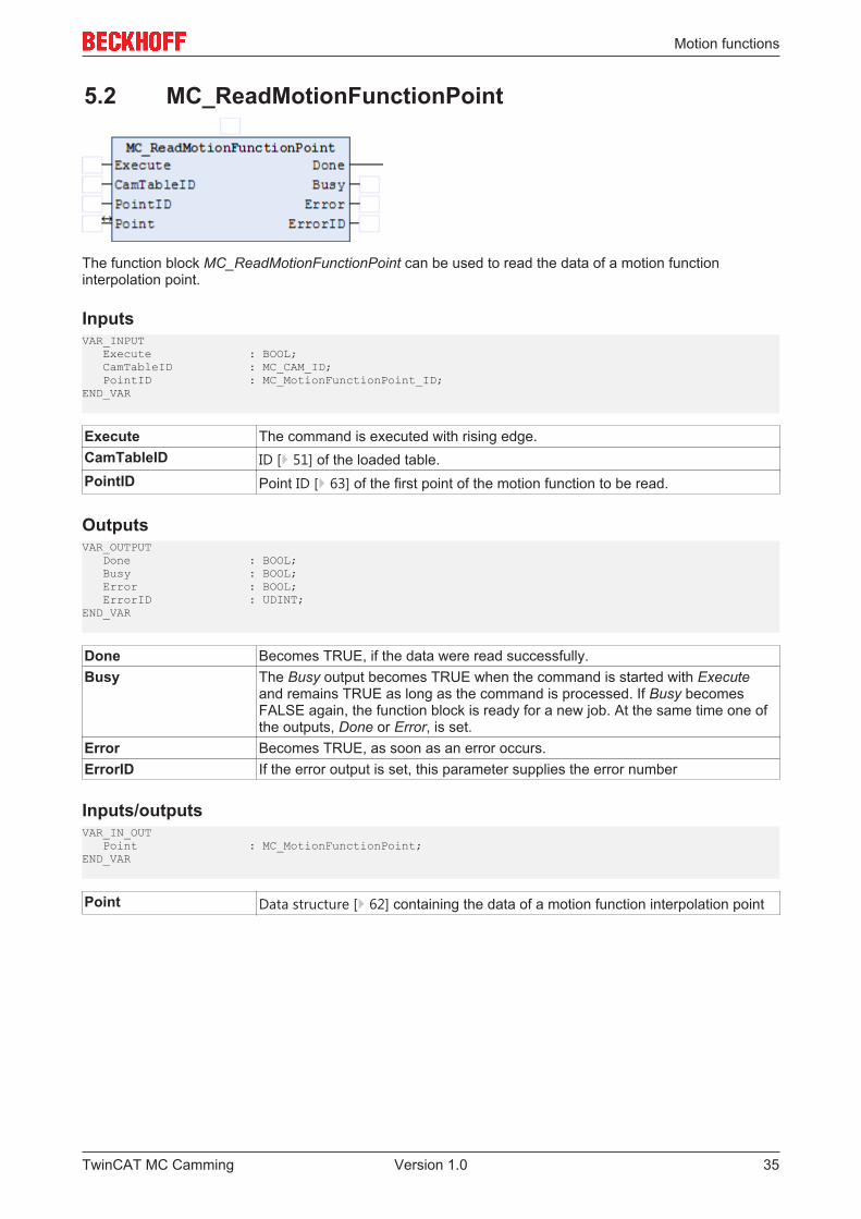
The function block MC_ReadMotionFunctionPoint can be used to read the data of a motion functioninterpolation point.
InputsVAR_INPUT Execute : BOOL; CamTableID : MC_CAM_ID; PointID : MC_MotionFunctionPoint_ID;END_VAR
Execute The command is executed with rising edge.CamTableID ID [} 51] of the loaded table.PointID Point ID [} 63] of the first point of the motion function to be read.
OutputsVAR_OUTPUT Done : BOOL; Busy : BOOL; Error : BOOL; ErrorID : UDINT;END_VAR
Done Becomes TRUE, if the data were read successfully.Busy The Busy output becomes TRUE when the command is started with Execute
and remains TRUE as long as the command is processed. If Busy becomesFALSE again, the function block is ready for a new job. At the same time one ofthe outputs, Done or Error, is set.
Error Becomes TRUE, as soon as an error occurs.ErrorID If the error output is set, this parameter supplies the error number
Inputs/outputsVAR_IN_OUT Point : MC_MotionFunctionPoint;END_VAR
Point Data structure [} 62] containing the data of a motion function interpolation point
TwinCAT MC Camming 35Version 1.0
Motion functions
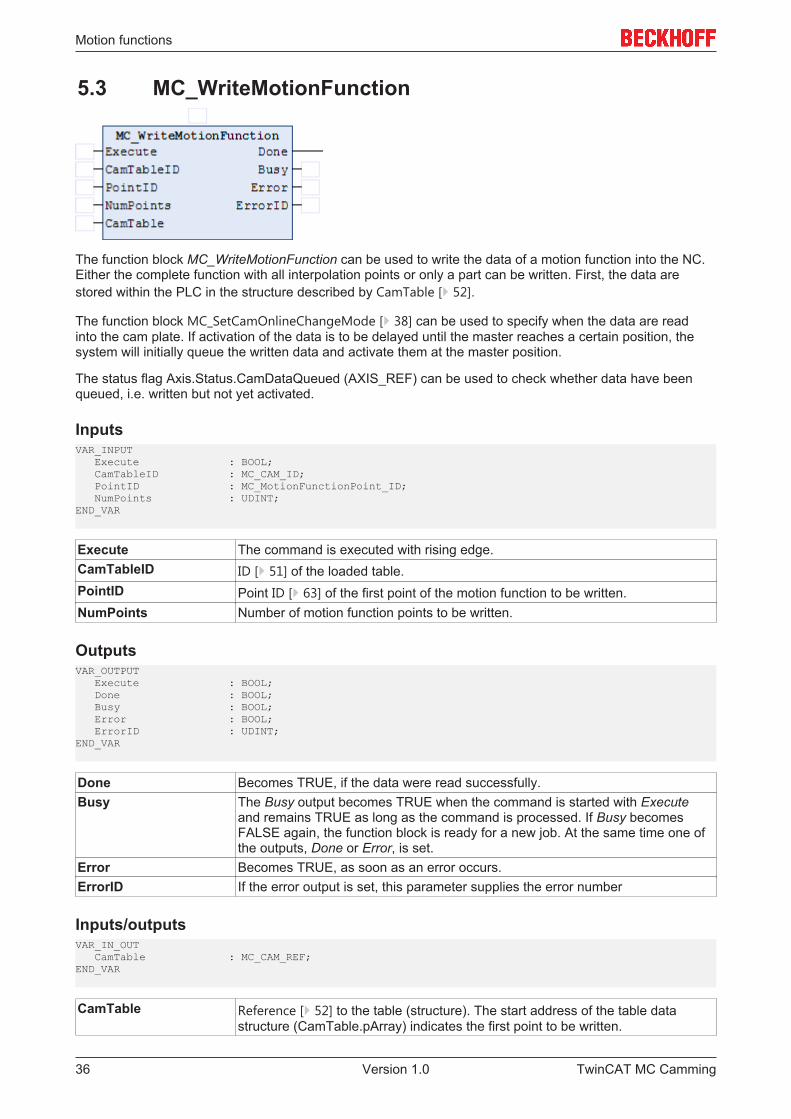
5.3 MC_WriteMotionFunction
The function block MC_WriteMotionFunction can be used to write the data of a motion function into the NC.Either the complete function with all interpolation points or only a part can be written. First, the data arestored within the PLC in the structure described by CamTable [} 52].
The function block MC_SetCamOnlineChangeMode [} 38] can be used to specify when the data are readinto the cam plate. If activation of the data is to be delayed until the master reaches a certain position, thesystem will initially queue the written data and activate them at the master position.
The status flag Axis.Status.CamDataQueued (AXIS_REF) can be used to check whether data have beenqueued, i.e. written but not yet activated.
InputsVAR_INPUT Execute : BOOL; CamTableID : MC_CAM_ID; PointID : MC_MotionFunctionPoint_ID; NumPoints : UDINT; END_VAR
Execute The command is executed with rising edge.CamTableID ID [} 51] of the loaded table.PointID Point ID [} 63] of the first point of the motion function to be written.NumPoints Number of motion function points to be written.
OutputsVAR_OUTPUT Execute : BOOL; Done : BOOL; Busy : BOOL; Error : BOOL; ErrorID : UDINT;END_VAR
Done Becomes TRUE, if the data were read successfully.Busy The Busy output becomes TRUE when the command is started with Execute
and remains TRUE as long as the command is processed. If Busy becomesFALSE again, the function block is ready for a new job. At the same time one ofthe outputs, Done or Error, is set.
Error Becomes TRUE, as soon as an error occurs.ErrorID If the error output is set, this parameter supplies the error number
Inputs/outputsVAR_IN_OUT CamTable : MC_CAM_REF;END_VAR
CamTable Reference [} 52] to the table (structure). The start address of the table datastructure (CamTable.pArray) indicates the first point to be written.
TwinCAT MC Camming36 Version 1.0
Motion functions
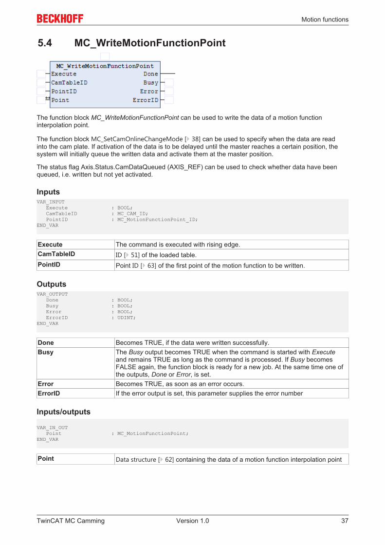
5.4 MC_WriteMotionFunctionPoint
The function block MC_WriteMotionFunctionPoint can be used to write the data of a motion functioninterpolation point.
The function block MC_SetCamOnlineChangeMode [} 38] can be used to specify when the data are readinto the cam plate. If activation of the data is to be delayed until the master reaches a certain position, thesystem will initially queue the written data and activate them at the master position.
The status flag Axis.Status.CamDataQueued (AXIS_REF) can be used to check whether data have beenqueued, i.e. written but not yet activated.
InputsVAR_INPUT Execute : BOOL; CamTableID : MC_CAM_ID; PointID : MC_MotionFunctionPoint_ID;END_VAR
Execute The command is executed with rising edge.CamTableID ID [} 51] of the loaded table.PointID Point ID [} 63] of the first point of the motion function to be written.
OutputsVAR_OUTPUT Done : BOOL; Busy : BOOL; Error : BOOL; ErrorID : UDINT;END_VAR
Done Becomes TRUE, if the data were written successfully.Busy The Busy output becomes TRUE when the command is started with Execute
and remains TRUE as long as the command is processed. If Busy becomesFALSE again, the function block is ready for a new job. At the same time one ofthe outputs, Done or Error, is set.
Error Becomes TRUE, as soon as an error occurs.ErrorID If the error output is set, this parameter supplies the error number
Inputs/outputs
VAR_IN_OUT Point : MC_MotionFunctionPoint;END_VAR
Point Data structure [} 62] containing the data of a motion function interpolation point
TwinCAT MC Camming 37Version 1.0
Motion functions
5.5 MC_SetCamOnlineChangeMode
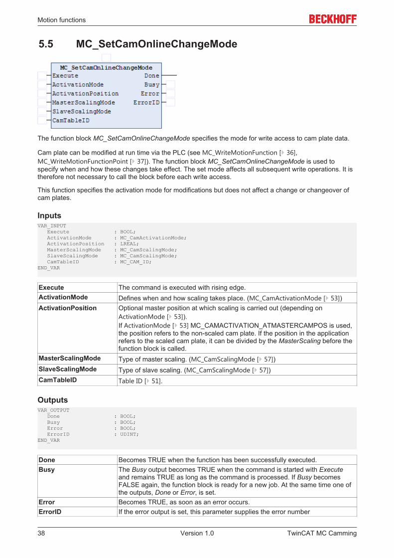
The function block MC_SetCamOnlineChangeMode specifies the mode for write access to cam plate data.
Cam plate can be modified at run time via the PLC (see MC_WriteMotionFunction [} 36],MC_WriteMotionFunctionPoint [} 37]). The function block MC_SetCamOnlineChangeMode is used tospecify when and how these changes take effect. The set mode affects all subsequent write operations. It istherefore not necessary to call the block before each write access.
This function specifies the activation mode for modifications but does not affect a change or changeover ofcam plates.
InputsVAR_INPUT Execute : BOOL; ActivationMode : MC_CamActivationMode; ActivationPosition : LREAL; MasterScalingMode : MC_CamScalingMode; SlaveScalingMode : MC_CamScalingMode; CamTableID : MC_CAM_ID;END_VAR
Execute The command is executed with rising edge.ActivationMode Defines when and how scaling takes place. (MC_CamActivationMode [} 53])ActivationPosition Optional master position at which scaling is carried out (depending on
ActivationMode [} 53]).If ActivationMode [} 53] MC_CAMACTIVATION_ATMASTERCAMPOS is used,the position refers to the non-scaled cam plate. If the position in the applicationrefers to the scaled cam plate, it can be divided by the MasterScaling before thefunction block is called.
MasterScalingMode Type of master scaling. (MC_CamScalingMode [} 57])SlaveScalingMode Type of slave scaling. (MC_CamScalingMode [} 57])CamTableID Table ID [} 51].
OutputsVAR_OUTPUT Done : BOOL; Busy : BOOL; Error : BOOL; ErrorID : UDINT;END_VAR
Done Becomes TRUE when the function has been successfully executed.Busy The Busy output becomes TRUE when the command is started with Execute
and remains TRUE as long as the command is processed. If Busy becomesFALSE again, the function block is ready for a new job. At the same time one ofthe outputs, Done or Error, is set.
Error Becomes TRUE, as soon as an error occurs.ErrorID If the error output is set, this parameter supplies the error number
TwinCAT MC Camming38 Version 1.0
Motion functions
5.6 MC_ReadMotionFunctionValues
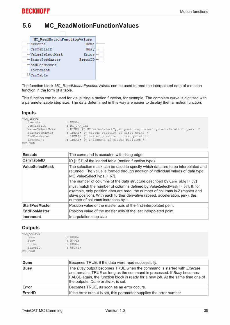
The function block MC_ReadMotionFunctionValues can be used to read the interpolated data of a motionfunction in the form of a table.
This function can be used for visualizing a motion function, for example. The complete curve is digitized witha parameterizable step size. The data determined in this way are easier to display then a motion function.
InputsVAR_INPUT Execute : BOOL; CamTableID : MC_CAM_ID; ValueSelectMask : UINT; (* MC_ValueSelectType; position, velocity, acceleration, jerk… *) StartPosMaster : LREAL; (* master position of first point *) EndPosMaster : LREAL; (* master position of last point *) Increment : LREAL; (* increment of master position *)END_VAR
Execute The command is executed with rising edge.CamTableID ID [} 51] of the loaded table (motion function type).ValueSelectMask The selection mask can be used to specify which data are to be interpolated and
returned. The value is formed through addition of individual values of data typeMC_ValueSelectType [} 67].The number of columns of the data structure described by CamTable [} 52]must match the number of columns defined by ValueSelectMask [} 67]. If, forexample, only position data are read, the number of columns is 2 (master andslave position). With each further derivative (speed, acceleration, jerk), thenumber of columns increases by 1.
StartPosMaster Position value of the master axis of the first interpolated pointEndPosMaster Position value of the master axis of the last interpolated pointIncrement Interpolation step size
OutputsVAR_OUTPUT Done : BOOL; Busy : BOOL; Error : BOOL; ErrorID : UDINT;END_VAR
Done Becomes TRUE, if the data were read successfully.Busy The Busy output becomes TRUE when the command is started with Execute
and remains TRUE as long as the command is processed. If Busy becomesFALSE again, the function block is ready for a new job. At the same time one ofthe outputs, Done or Error, is set.
Error Becomes TRUE, as soon as an error occurs.ErrorID If the error output is set, this parameter supplies the error number
TwinCAT MC Camming 39Version 1.0
Motion functions
Inputs/outputsVAR_IN_OUT CamTable : MC_CAM_REF;END_VAR
CamTable Reference [} 52] to the table (structure).
TwinCAT MC Camming40 Version 1.0
Status
6 Status
6.1 MC_ReadCamTableSlaveDynamics
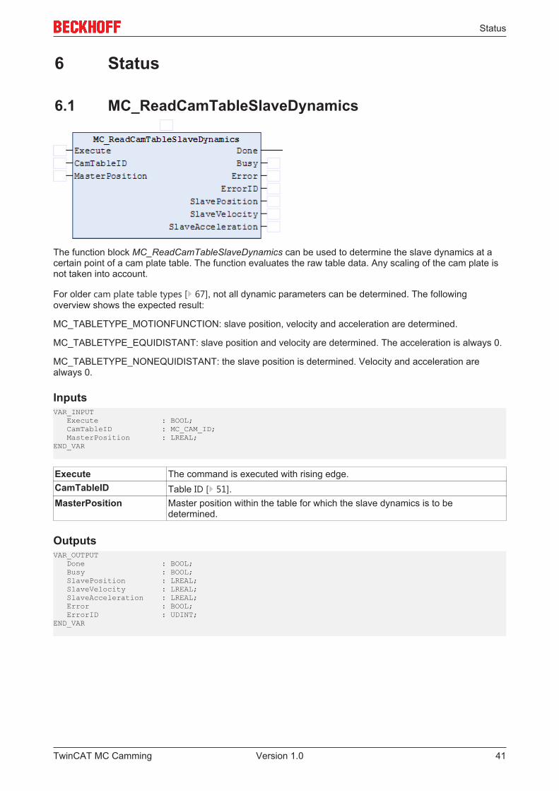
The function block MC_ReadCamTableSlaveDynamics can be used to determine the slave dynamics at acertain point of a cam plate table. The function evaluates the raw table data. Any scaling of the cam plate isnot taken into account.
For older cam plate table types [} 67], not all dynamic parameters can be determined. The followingoverview shows the expected result:
MC_TABLETYPE_MOTIONFUNCTION: slave position, velocity and acceleration are determined.
MC_TABLETYPE_EQUIDISTANT: slave position and velocity are determined. The acceleration is always 0.
MC_TABLETYPE_NONEQUIDISTANT: the slave position is determined. Velocity and acceleration arealways 0.
InputsVAR_INPUT Execute : BOOL; CamTableID : MC_CAM_ID; MasterPosition : LREAL;END_VAR
Execute The command is executed with rising edge.CamTableID Table ID [} 51].MasterPosition Master position within the table for which the slave dynamics is to be
determined.
OutputsVAR_OUTPUT Done : BOOL; Busy : BOOL; SlavePosition : LREAL; SlaveVelocity : LREAL; SlaveAcceleration : LREAL; Error : BOOL; ErrorID : UDINT;END_VAR
TwinCAT MC Camming 41Version 1.0
Status
Done Becomes TRUE, if the command was executed successfully.Busy The Busy output becomes TRUE when the command is started with Execute
and remains TRUE as long as the command is processed. If Busy becomesFALSE again, the function block is ready for a new job. At the same time one ofthe outputs, Done or Error, is set.
SlavePosition Position of the slave within the cam plate table at the specified master position.SlaveVelocity Velocity of the slave within the cam plate table at the specified master position.SlaveAcceleration Acceleration of the slave within the cam plate table at the specified master
position.Error Becomes TRUE, as soon as an error occurs.ErrorID If the error output is set, this parameter supplies the error number
TwinCAT MC Camming42 Version 1.0
Status
6.2 MC_CamInfo
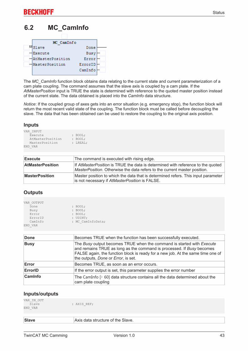
The MC_CamInfo function block obtains data relating to the current state and current parameterization of acam plate coupling. The command assumes that the slave axis is coupled by a cam plate. If theAtMasterPosition input is TRUE the state is determined with reference to the quoted master position insteadof the current state. The data obtained is placed into the CamInfo data structure.
Notice: If the coupled group of axes gets into an error situation (e.g. emergency stop), the function block willreturn the most recent valid state of the coupling. The function block must be called before decoupling theslave. The data that has been obtained can be used to restore the coupling to the original axis position.
InputsVAR_INPUT Execute : BOOL; AtMasterPosition : BOOL; MasterPosition : LREAL;END_VAR
Execute The command is executed with rising edge.AtMasterPosition If AtMasterPosition is TRUE the data is determined with reference to the quoted
MasterPosition. Otherwise the data refers to the current master position.MasterPosition Master position to which the data that is determined refers. This input parameter
is not necessary if AtMasterPosition is FALSE.
Outputs
VAR_OUTPUT Done : BOOL; Busy : BOOL; Error : BOOL; ErrorID : UDINT; CamInfo : MC_CamInfoData;END_VAR
Done Becomes TRUE when the function has been successfully executed.Busy The Busy output becomes TRUE when the command is started with Execute
and remains TRUE as long as the command is processed. If Busy becomesFALSE again, the function block is ready for a new job. At the same time one ofthe outputs, Done or Error, is set.
Error Becomes TRUE, as soon as an error occurs.ErrorID If the error output is set, this parameter supplies the error numberCamInfo The CamInfo [} 60] data structure contains all the data determined about the
cam plate coupling
Inputs/outputsVAR_IN_OUT Slave : AXIS_REF;END_VAR
Slave Axis data structure of the Slave.
TwinCAT MC Camming 43Version 1.0
Status
The axis data structure of type AXIS_REF addresses an axis uniquely within the system. Among otherparameters it contains the current axis status, including position, velocity or error status.
TwinCAT MC Camming44 Version 1.0
Status
6.3 MC_CamInfo_V2
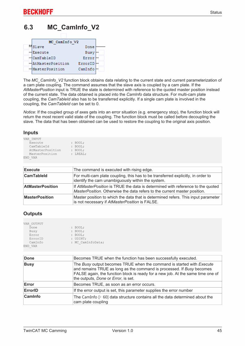
The MC_CamInfo_V2 function block obtains data relating to the current state and current parameterization ofa cam plate coupling. The command assumes that the slave axis is coupled by a cam plate. If theAtMasterPosition input is TRUE the state is determined with reference to the quoted master position insteadof the current state. The data obtained is placed into the CamInfo data structure. For multi-cam platecoupling, the CamTableId also has to be transferred explicitly. If a single cam plate is involved in thecoupling, the CamTableId can be set to 0.
Notice: If the coupled group of axes gets into an error situation (e.g. emergency stop), the function block willreturn the most recent valid state of the coupling. The function block must be called before decoupling theslave. The data that has been obtained can be used to restore the coupling to the original axis position.
InputsVAR_INPUT Execute : BOOL; CamTableId : BOOL; AtMasterPosition : BOOL; MasterPosition : LREAL;END_VAR
Execute The command is executed with rising edge.CamTableId For multi-cam plate coupling, this has to be transferred explicitly, in order to
identify the cam unambiguously within the system.AtMasterPosition If AtMasterPosition is TRUE the data is determined with reference to the quoted
MasterPosition. Otherwise the data refers to the current master position.MasterPosition Master position to which the data that is determined refers. This input parameter
is not necessary if AtMasterPosition is FALSE.
Outputs
VAR_OUTPUT Done : BOOL; Busy : BOOL; Error : BOOL; ErrorID : UDINT; CamInfo : MC_CamInfoData;END_VAR
Done Becomes TRUE when the function has been successfully executed.Busy The Busy output becomes TRUE when the command is started with Execute
and remains TRUE as long as the command is processed. If Busy becomesFALSE again, the function block is ready for a new job. At the same time one ofthe outputs, Done or Error, is set.
Error Becomes TRUE, as soon as an error occurs.ErrorID If the error output is set, this parameter supplies the error numberCamInfo The CamInfo [} 60] data structure contains all the data determined about the
cam plate coupling
TwinCAT MC Camming 45Version 1.0

Status
Inputs/outputsVAR_IN_OUT Slave : AXIS_REF;END_VAR
Slave Axis data structure of the Slave.
The axis data structure of type AXIS_REF addresses an axis uniquely within the system. Among otherparameters it contains the current axis status, including position, velocity or error status.
TwinCAT MC Camming46 Version 1.0
Status
6.4 MC_ReadCamTableCharacteristics
The function block MC_ReadCamTableCharacteristics is used to calculate and read the characteristicparameters of a motion function. This includes minimum and maximum values of position, velocity,acceleration and jerk.
InputsVAR_INPUT Execute : BOOL; CamTableID : MC_CAM_ID;END_VAR
Execute The command is executed with rising edge.CamTableID Table ID [} 51]
OutputsVAR_OUTPUT Done : BOOL; Busy : BOOL; Error : BOOL; ErrorID : UDINT;END_VAR
Done Becomes TRUE, if the calculation was carried out successfully.Busy The Busy output becomes TRUE when the command is started with Execute
and remains TRUE as long as the command is processed. If Busy becomesFALSE again, the function block is ready for a new job. At the same time one ofthe outputs, Done or Error, is set.
Error Becomes TRUE, as soon as an error occurs.ErrorID If the error output is set, this parameter supplies the error number
Inputs/outputsVAR_IN_OUT CamTableCharac : MC_TableCharacValues;END_VAR
CamTableCharac: Data structure [} 66] with characteristic parameters of the motion function
TwinCAT MC Camming 47Version 1.0
Status
6.5 MC_ReadCamTableMasterPosition
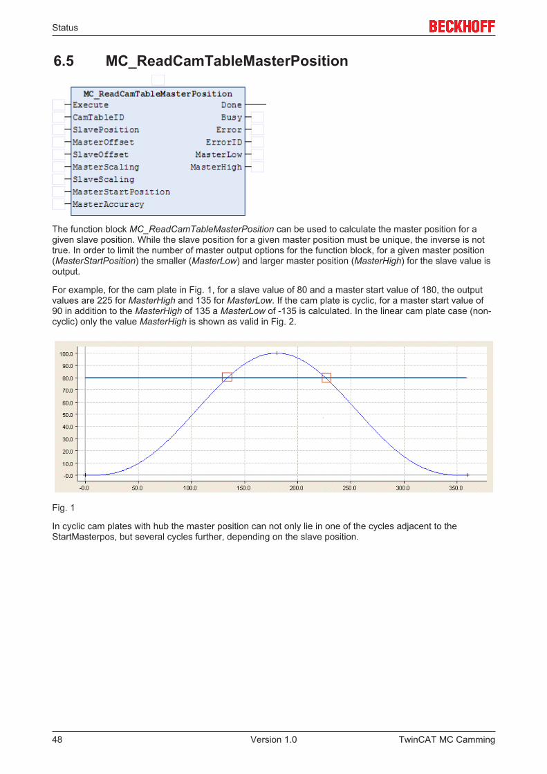
The function block MC_ReadCamTableMasterPosition can be used to calculate the master position for agiven slave position. While the slave position for a given master position must be unique, the inverse is nottrue. In order to limit the number of master output options for the function block, for a given master position(MasterStartPosition) the smaller (MasterLow) and larger master position (MasterHigh) for the slave value isoutput.
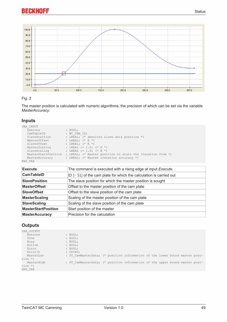
For example, for the cam plate in Fig. 1, for a slave value of 80 and a master start value of 180, the outputvalues are 225 for MasterHigh and 135 for MasterLow. If the cam plate is cyclic, for a master start value of90 in addition to the MasterHigh of 135 a MasterLow of -135 is calculated. In the linear cam plate case (non-cyclic) only the value MasterHigh is shown as valid in Fig. 2.
Fig. 1
In cyclic cam plates with hub the master position can not only lie in one of the cycles adjacent to theStartMasterpos, but several cycles further, depending on the slave position.
TwinCAT MC Camming48 Version 1.0
Status
Fig. 2
The master position is calculated with numeric algorithms, the precision of which can be set via the variableMasterAccuracy.
InputsVAR_INPUT Execute : BOOL; CamTableID : MC_CAM_ID; SlavePosition : LREAL; (* absolute slave axis position *) MasterOffset : LREAL; (* E *) SlaveOffset : LREAL; (* E *) MasterScaling : LREAL := 1.0; (* E *) SlaveScaling : LREAL := 1.0; (* E *) MasterStartPosition : LREAL; (* Master position to start the iteration from *) MasterAccuracy : LREAL; (* Master iteration accuracy *)END_VAR
Execute The command is executed with a rising edge at input Execute.CamTableID ID [} 51] of the cam plate for which the calculation is carried outSlavePosition The slave position for which the master position is soughtMasterOffset Offset to the master position of the cam plateSlaveOffset Offset to the slave position of the cam plateMasterScaling Scaling of the master position of the cam plateSlaveScaling Scaling of the slave position of the cam plateMasterStartPosition Start position of the masterMasterAccuracy Precision for the calculation
OutputsVAR_OUTPUT Execute : BOOL; Done : BOOL; Busy : BOOL; Active : BOOL; Error : BOOL; ErrorID : UDINT; MasterLow : ST_CamMasterData; (* position information of the lower bound master posi-tion *) MasterHigh : ST_CamMasterData; (* position information of the upper bound master posi-tion *)END_VAR
TwinCAT MC Camming 49Version 1.0
Status
Done Becomes TRUE, if the coupling was successful and the cam plate is active.Busy The Busy output becomes TRUE when the command is started with Execute
and remains TRUE as long as the command is processed. If Busy becomesFALSE again, the function block is ready for a new job. At the same time one ofthe outputs, Done or Error, is set.
Error Becomes TRUE, as soon as an error occurs.ErrorID If the error output is set, this parameter supplies the error numberMasterLow Master position is smaller than the MasterStartPosition in the data structure
ST_CamMasterData [} 70]MasterHigh Master position is smaller than the MasterStartPosition in the data structure
ST_CamMasterData [} 70]
TwinCAT MC Camming50 Version 1.0
Data type
7 Data type
7.1 Data type MC_CAM_IDTYPE MC_CAM_ID : UDINT;END_TYPE
Type definition for the tables ID.
TwinCAT MC Camming 51Version 1.0
Data type
7.2 Data type MC_CAM_REFTYPE MC_CAM_REF :STRUCT pArray : UDINT; ArraySize : UDINT; TableType : MC_TableType; NoOfRows : UDINT; NoOfColumns : UDINT;END_STRUCTEND_TYPE
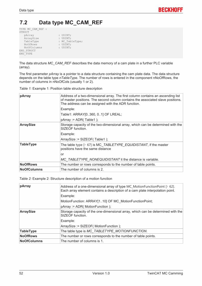
The data structure MC_CAM_REF describes the data memory of a cam plate in a further PLC variable(array).
The first parameter pArray is a pointer to a data structure containing the cam plate data. The data structuredepends on the table type nTableType. The number of rows is entered in the component nNoOfRows, thenumber of columns in nNoOfCols (usually 1 or 2).
Table 1: Example 1: Position table structure description
pArray Address of a two-dimensional array. The first column contains an ascending listof master positions. The second column contains the associated slave positions.The address can be assigned with the ADR function.Example:Table1: ARRAY[0..360, 0..1] OF LREAL;pArray := ADR( Table1 );
ArraySize Storage capacity of the two-dimensional array, which can be determined with theSIZEOF function.Example:ArraySize := SIZEOF( Table1 );
TableType The table type [} 67] is MC_TABLETYPE_EQUIDISTANT, if the masterpositions have the same distanceorMC_TABLETYPE_NONEQUIDISTANT it the distance is variable.
NoOfRows The number or rows corresponds to the number of table points.NoOfColumns The number of columns is 2.
Table 2: Example 2: Structure description of a motion function
pArray Address of a one-dimensional array of type MC_MotionFunctionPoint [} 62].Each array element contains a description of a cam plate interpolation point.Example:MotionFunction: ARRAY[1..10] OF MC_MotionFunctionPoint;pArray := ADR( MotionFunction );
ArraySize Storage capacity of the one-dimensional array, which can be determined with theSIZEOF function.Example:ArraySize := SIZEOF( MotionFunction );
TableType The table type is MC_TABLETYPE_MOTIONFUNCTION.NoOfRows The number or rows corresponds to the number of table points.NoOfColumns The number of columns is 1.
TwinCAT MC Camming52 Version 1.0
Data type
7.3 Data type MC_CamActivationModeTYPE MC_CamActivationMode :( (* instantaneous change *) MC_CAMACTIVATION_INSTANTANEOUS,
(* modify the data at a defined master position referring to the cam tables master position *) MC_CAMACTIVATION_ATMASTERCAMPOS,
(* modify the data at a defined master position referring to the absolute master axis position *) MC_CAMACTIVATION_ATMASTERAXISPOS
(* modify the data at the beginning of the next cam table cycle *) MC_CAMACTIVATION_NEXTCYCLE,
(* not yet implemented! modify the data at the beginning of the next cam table cycle, activation is valid for one cycleonly *) MC_CAMACTIVATION_NEXTCYCLEONCE,
(* modify the data as soon as the cam table is in a safe state to change its data *) MC_CAMACTIVATION_ASSOONASPOSSIBLE,
(* don't accept any modification *) MC_CAMACTIVATION_OFF,
(* delete all data which was written to modify the cam table but is still not activated *) MC_CAMACTIVATION_DELETEQUEUEDDATA,
(* special mode at a defined master axis position in a defined positive direction *) MC_CAMACTIVATION_ATMASTERAXISPOS_POSITVEDIRECTION,
(* special mode at a defined master axis position in a defined negative direction *) MC_CAMACTIVATION_ATMASTERAXISPOS_NEGATIVEDIRECTION );END_TYPE
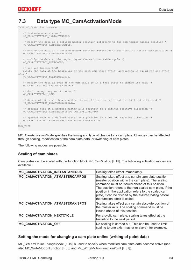
MC_CamActivationMode specifies the timing and type of change for a cam plate. Changes can be affectedthrough scaling, modification of the cam plate data, or switching of cam plates.
The following modes are possible:
Scaling of cam plates
Cam plates can be scaled with the function block MC_CamScaling [} 18]. The following activation modes areavailable.
MC_CAMACTIVATION_INSTANTANEOUS Scaling takes effect immediately.MC_CAMACTIVATION_ATMASTERCAMPOS Scaling takes effect at a certain cam plate position
(master position within the cam plate). The scalingcommand must be issued ahead of this position.The position refers to the non-scaled cam plate. If theposition in the application refers to the scaled camplate, it can be divided by the MasterScaling beforethe function block is called.
MC_CAMACTIVATION_ATMASTERAXISPOS Scaling takes effect at a certain absolute position ofthe master axis. The scaling command must beissued ahead of this position.
MC_CAMACTIVATION_NEXTCYCLE For a cyclic cam plate, scaling takes effect at thetransition to the next period.
MC_CAMACTIVATION_OFF No scaling is carried out. This can be used to limitscaling to one axis (master or slave), for example.
Setting the mode for changing a cam plate online (writing of point data)
MC_SetCamOnlineChangeMode [} 38] is used to specify when modified cam plate data become active (seealso MC_WriteMotionFunction [} 36] and MC_WriteMotionFunctionPoint [} 37]).
TwinCAT MC Camming 53Version 1.0
Data type
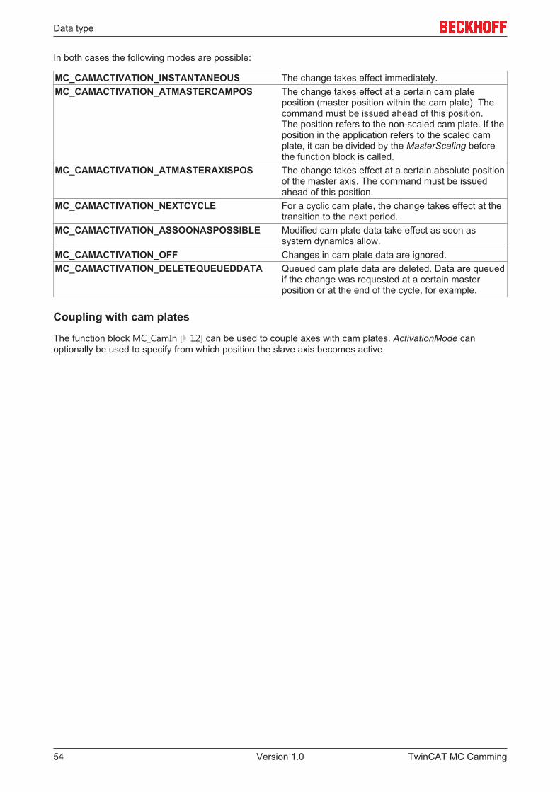
In both cases the following modes are possible:
MC_CAMACTIVATION_INSTANTANEOUS The change takes effect immediately.MC_CAMACTIVATION_ATMASTERCAMPOS The change takes effect at a certain cam plate
position (master position within the cam plate). Thecommand must be issued ahead of this position.The position refers to the non-scaled cam plate. If theposition in the application refers to the scaled camplate, it can be divided by the MasterScaling beforethe function block is called.
MC_CAMACTIVATION_ATMASTERAXISPOS The change takes effect at a certain absolute positionof the master axis. The command must be issuedahead of this position.
MC_CAMACTIVATION_NEXTCYCLE For a cyclic cam plate, the change takes effect at thetransition to the next period.
MC_CAMACTIVATION_ASSOONASPOSSIBLE Modified cam plate data take effect as soon assystem dynamics allow.
MC_CAMACTIVATION_OFF Changes in cam plate data are ignored.MC_CAMACTIVATION_DELETEQUEUEDDATA Queued cam plate data are deleted. Data are queued
if the change was requested at a certain masterposition or at the end of the cycle, for example.
Coupling with cam plates
The function block MC_CamIn [} 12] can be used to couple axes with cam plates. ActivationMode canoptionally be used to specify from which position the slave axis becomes active.
TwinCAT MC Camming54 Version 1.0
Data type
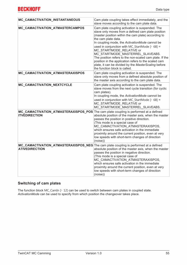
MC_CAMACTIVATION_INSTANTANEOUS Cam plate coupling takes effect immediately, and theslave moves according to the cam plate data.
MC_CAMACTIVATION_ATMASTERCAMPOS Cam plate coupling activation is suspended. Theslave only moves from a defined cam plate position(master position within the cam plate) according tothe cam plate data.In coupling mode, the ActivationMode cannot beused in conjunction with MC_StartMode [} 68] =MC_STARTMODE_RELATIVE orMC_STARTMODE_MASTERREL_SLAVEABS.The position refers to the non-scaled cam plate. If theposition in the application refers to the scaled camplate, it can be divided by the MasterScaling beforethe function block is called.
MC_CAMACTIVATION_ATMASTERAXISPOS Cam plate coupling activation is suspended. Theslave only moves from a defined absolute position ofthe master axis according to the cam plate data.
MC_CAMACTIVATION_NEXTCYCLE Cam plate coupling activation is suspended. Theslave moves from the next cycle transition (for cycliccam plates).In coupling mode, the ActivationMode cannot beused in conjunction with MC_StartMode [} 68] =MC_STARTMODE_RELATIVE orMC_STARTMODE_MASTERREL_SLAVEABS.
MC_CAMACTIVATION_ATMASTERAXISPOS_POSITVEDIRECTION
The cam plate coupling is performed at a definedabsolute position of the master axis, when the masterpasses the position in positive direction.(This mode is a special case ofMC_CAMACTIVATION_ATMASTERAXISPOS,which ensures safe activation in the immediateproximity around the current position, even at verylow speeds with short-term changes of direction(noise))
MC_CAMACTIVATION_ATMASTERAXISPOS_NEGATIVEDIRECTION
The cam plate coupling is performed at a definedabsolute position of the master axis, when the masterpasses the position in negative direction.(This mode is a special case ofMC_CAMACTIVATION_ATMASTERAXISPOS,which ensures safe activation in the immediateproximity around the current position, even at verylow speeds with short-term changes of direction(noise))
Switching of cam plates
The function block MC_CamIn [} 12] can be used to switch between cam plates in coupled state.ActivationMode can be used to specify from which position the changeover takes place.
TwinCAT MC Camming 55Version 1.0
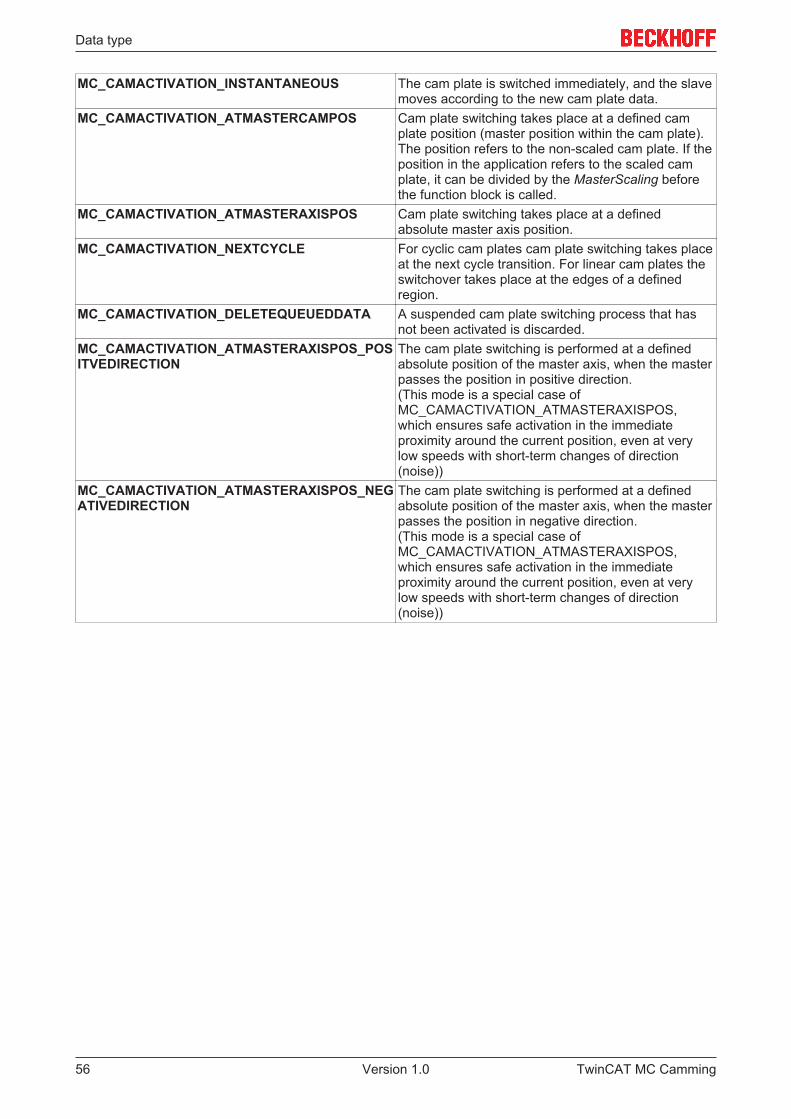
Data type
MC_CAMACTIVATION_INSTANTANEOUS The cam plate is switched immediately, and the slavemoves according to the new cam plate data.
MC_CAMACTIVATION_ATMASTERCAMPOS Cam plate switching takes place at a defined camplate position (master position within the cam plate).The position refers to the non-scaled cam plate. If theposition in the application refers to the scaled camplate, it can be divided by the MasterScaling beforethe function block is called.
MC_CAMACTIVATION_ATMASTERAXISPOS Cam plate switching takes place at a definedabsolute master axis position.
MC_CAMACTIVATION_NEXTCYCLE For cyclic cam plates cam plate switching takes placeat the next cycle transition. For linear cam plates theswitchover takes place at the edges of a definedregion.
MC_CAMACTIVATION_DELETEQUEUEDDATA A suspended cam plate switching process that hasnot been activated is discarded.
MC_CAMACTIVATION_ATMASTERAXISPOS_POSITVEDIRECTION
The cam plate switching is performed at a definedabsolute position of the master axis, when the masterpasses the position in positive direction.(This mode is a special case ofMC_CAMACTIVATION_ATMASTERAXISPOS,which ensures safe activation in the immediateproximity around the current position, even at verylow speeds with short-term changes of direction(noise))
MC_CAMACTIVATION_ATMASTERAXISPOS_NEGATIVEDIRECTION
The cam plate switching is performed at a definedabsolute position of the master axis, when the masterpasses the position in negative direction.(This mode is a special case ofMC_CAMACTIVATION_ATMASTERAXISPOS,which ensures safe activation in the immediateproximity around the current position, even at verylow speeds with short-term changes of direction(noise))
TwinCAT MC Camming56 Version 1.0
Data type
7.4 Data type MC_CamScalingModeTYPE MC_CamScalingMode :( (* user defines scaling parameters -scaling and -offset *) MC_CAMSCALING_USERDEFINED,
(* offset is calculated automatically for best result *) MC_CAMSCALING_AUTOOFFSET,
(* no modification accepted *) MC_CAMSCALING_OFF );END_TYPE
Type and scope of the scaling of a cam plate coupling via function block MC_CamScaling [} 18].
MC_CAMSCALING_USERDEFINED : The scaling and offset are retained unchanged. The user has tocalculate the scaling and offset such that a jump in the position is avoided.
MC_CAMSCALING_AUTOOFFSET : The scaling takes effect and the system adjusts the offset such that ajump in the position is avoided. Scaling should nevertheless occur during a phase with slave velocity 0, sinceotherwise a jump in velocity cannot be avoided.
MC_CAMSCALING_OFF: The scaling and offset are ignored. This mode is used when only slave scaling(i.e. without master scaling) is to be implemented.
AutooffsetAutooffset mode ensures automatic adaptation of a cam plate offset. Autooffset can be used independentlyfor the master or slave axis of a cam plate and affects both switchover and scaling of cam plates. Thefunction operates based on the rules described below.
Master-AutooffsetMaster-Autooffset prevents discontinuity of the master position of the cam plate in the axis coordinatesystem during switching of cam plates with different master cycle or scaling of cam plates (master scaling).This function is required because the relative position of a cam plate in the axis coordinate system dependson the master cycle. If the master cycle is changed, e.g. through scaling, the position would change.
As a rule, Master Autooffset assumes that a cam plate already exists as reference for the corresponding axiscoupling. This option is therefore not available during initial coupling. Master-Autooffset determines themaster offset of the cam plate such that the master position within the cam plate is maintained. For scaling orswitchover to a cam plate with a different master cycle this means that the relative (percentage) positionbefore and after the switchover is identical.
Example: A cam plate has master cycle of 360° and is scaled by a factor of 2 to 720°. Scaling takes place atthe 90° position within the cam plate, i.e. at 25 % of the start of a cycle. After the scaling the relative masterposition in the cam plate at 180° is therefore also 25 % of the start of a cycle.
TwinCAT MC Camming 57Version 1.0
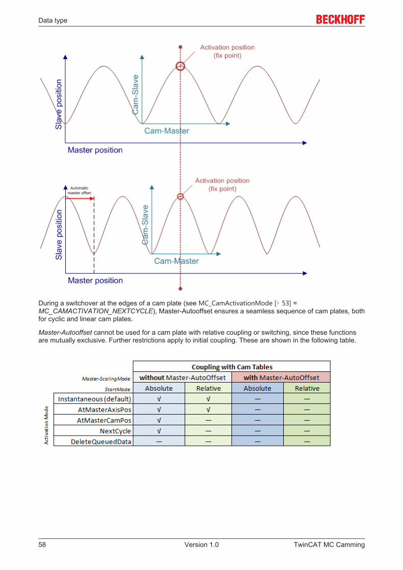
Data type
During a switchover at the edges of a cam plate (see MC_CamActivationMode [} 53] =MC_CAMACTIVATION_NEXTCYCLE), Master-Autooffset ensures a seamless sequence of cam plates, bothfor cyclic and linear cam plates.
Master-Autooffset cannot be used for a cam plate with relative coupling or switching, since these functionsare mutually exclusive. Further restrictions apply to initial coupling. These are shown in the following table.
TwinCAT MC Camming58 Version 1.0
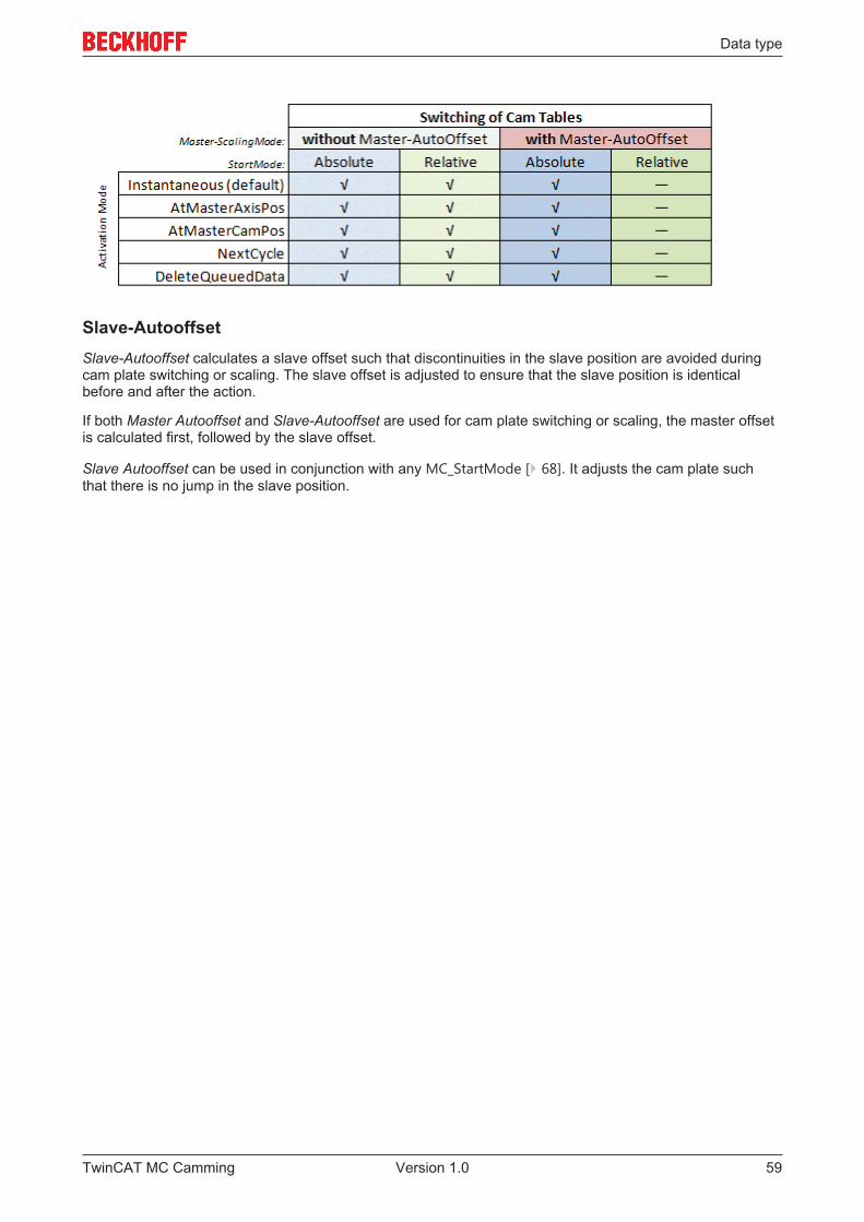
Data type
Slave-AutooffsetSlave-Autooffset calculates a slave offset such that discontinuities in the slave position are avoided duringcam plate switching or scaling. The slave offset is adjusted to ensure that the slave position is identicalbefore and after the action.
If both Master Autooffset and Slave-Autooffset are used for cam plate switching or scaling, the master offsetis calculated first, followed by the slave offset.
Slave Autooffset can be used in conjunction with any MC_StartMode [} 68]. It adjusts the cam plate suchthat there is no jump in the slave position.
TwinCAT MC Camming 59Version 1.0
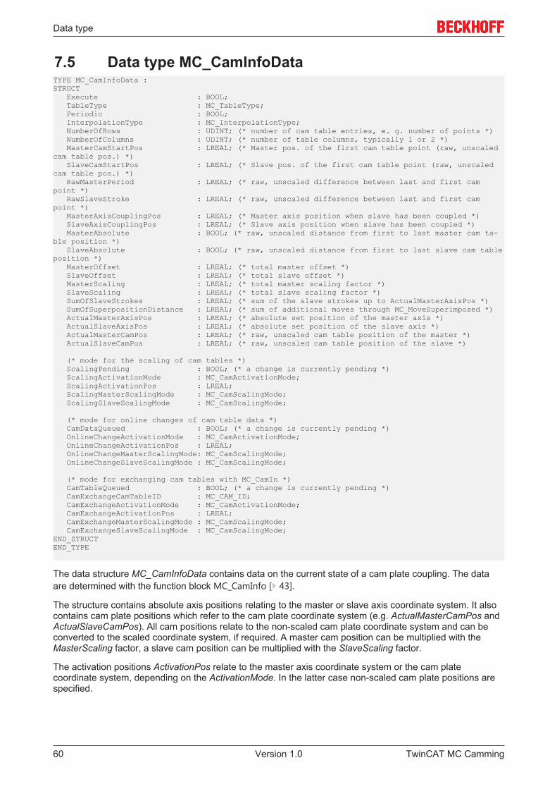
Data type
7.5 Data type MC_CamInfoDataTYPE MC_CamInfoData :STRUCT Execute : BOOL; TableType : MC_TableType; Periodic : BOOL; InterpolationType : MC_InterpolationType; NumberOfRows : UDINT; (* number of cam table entries, e. g. number of points *) NumberOfColumns : UDINT; (* number of table columns, typically 1 or 2 *) MasterCamStartPos : LREAL; (* Master pos. of the first cam table point (raw, unscaledcam table pos.) *) SlaveCamStartPos : LREAL; (* Slave pos. of the first cam table point (raw, unscaledcam table pos.) *) RawMasterPeriod : LREAL; (* raw, unscaled difference between last and first campoint *) RawSlaveStroke : LREAL; (* raw, unscaled difference between last and first campoint *) MasterAxisCouplingPos : LREAL; (* Master axis position when slave has been coupled *) SlaveAxisCouplingPos : LREAL; (* Slave axis position when slave has been coupled *) MasterAbsolute : BOOL; (* raw, unscaled distance from first to last master cam ta-ble position *) SlaveAbsolute : BOOL; (* raw, unscaled distance from first to last slave cam tableposition *) MasterOffset : LREAL; (* total master offset *) SlaveOffset : LREAL; (* total slave offset *) MasterScaling : LREAL; (* total master scaling factor *) SlaveScaling : LREAL; (* total slave scaling factor *) SumOfSlaveStrokes : LREAL; (* sum of the slave strokes up to ActualMasterAxisPos *) SumOfSuperpositionDistance : LREAL; (* sum of additional moves through MC_MoveSuperimposed *) ActualMasterAxisPos : LREAL; (* absolute set position of the master axis *) ActualSlaveAxisPos : LREAL; (* absolute set position of the slave axis *) ActualMasterCamPos : LREAL; (* raw, unscaled cam table position of the master *) ActualSlaveCamPos : LREAL; (* raw, unscaled cam table position of the slave *)
(* mode for the scaling of cam tables *) ScalingPending : BOOL; (* a change is currently pending *) ScalingActivationMode : MC_CamActivationMode; ScalingActivationPos : LREAL; ScalingMasterScalingMode : MC_CamScalingMode; ScalingSlaveScalingMode : MC_CamScalingMode;
(* mode for online changes of cam table data *) CamDataQueued : BOOL; (* a change is currently pending *) OnlineChangeActivationMode : MC_CamActivationMode; OnlineChangeActivationPos : LREAL; OnlineChangeMasterScalingMode: MC_CamScalingMode; OnlineChangeSlaveScalingMode : MC_CamScalingMode;
(* mode for exchanging cam tables with MC_CamIn *) CamTableQueued : BOOL; (* a change is currently pending *) CamExchangeCamTableID : MC_CAM_ID; CamExchangeActivationMode : MC_CamActivationMode; CamExchangeActivationPos : LREAL; CamExchangeMasterScalingMode : MC_CamScalingMode; CamExchangeSlaveScalingMode : MC_CamScalingMode;END_STRUCTEND_TYPE
The data structure MC_CamInfoData contains data on the current state of a cam plate coupling. The dataare determined with the function block MC_CamInfo [} 43].
The structure contains absolute axis positions relating to the master or slave axis coordinate system. It alsocontains cam plate positions which refer to the cam plate coordinate system (e.g. ActualMasterCamPos andActualSlaveCamPos). All cam positions relate to the non-scaled cam plate coordinate system and can beconverted to the scaled coordinate system, if required. A master cam position can be multiplied with theMasterScaling factor, a slave cam position can be multiplied with the SlaveScaling factor.
The activation positions ActivationPos relate to the master axis coordinate system or the cam platecoordinate system, depending on the ActivationMode. In the latter case non-scaled cam plate positions arespecified.
TwinCAT MC Camming60 Version 1.0
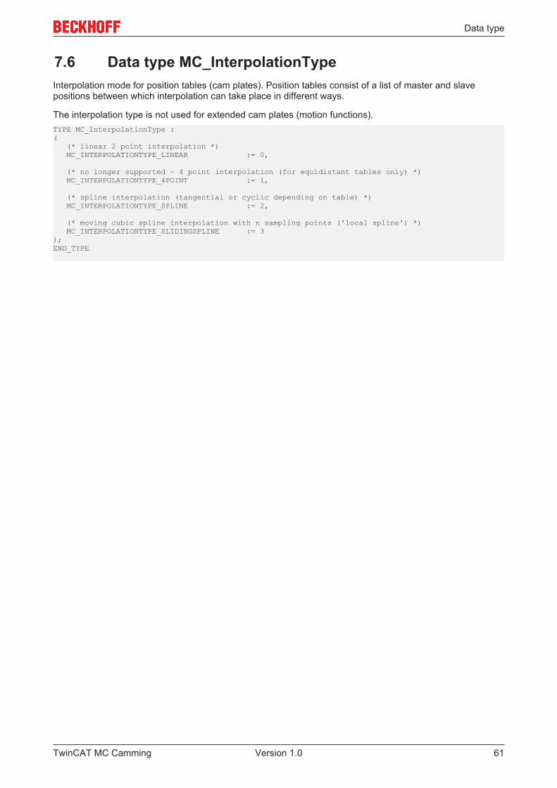
Data type
7.6 Data type MC_InterpolationTypeInterpolation mode for position tables (cam plates). Position tables consist of a list of master and slavepositions between which interpolation can take place in different ways.
The interpolation type is not used for extended cam plates (motion functions).TYPE MC_InterpolationType :( (* linear 2 point interpolation *) MC_INTERPOLATIONTYPE_LINEAR := 0,
(* no longer supported - 4 point interpolation (for equidistant tables only) *) MC_INTERPOLATIONTYPE_4POINT := 1,
(* spline interpolation (tangential or cyclic depending on table) *) MC_INTERPOLATIONTYPE_SPLINE := 2,
(* moving cubic spline interpolation with n sampling points ('local spline') *) MC_INTERPOLATIONTYPE_SLIDINGSPLINE := 3);END_TYPE
TwinCAT MC Camming 61Version 1.0
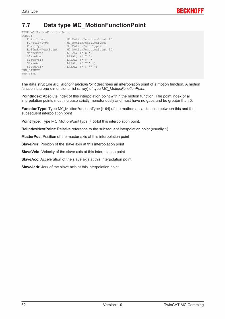
Data type
7.7 Data type MC_MotionFunctionPointTYPE MC_MotionFunctionPoint :STRUCT PointIndex : MC_MotionFunctionPoint_ID; FunctionType : MC_MotionFunctionType; PointType : MC_MotionPointType; RelIndexNextPoint : MC_MotionFunctionPoint_ID; MasterPos : LREAL; (* X *) SlavePos : LREAL; (* Y *) SlaveVelo : LREAL; (* Y' *) SlaveAcc : LREAL; (* Y'' *) SlaveJerk : LREAL; (* Y''' *)END_STRUCTEND_TYPE
The data structure MC_MotionFunctionPoint describes an interpolation point of a motion function. A motionfunction is a one-dimensional list (array) of type MC_MotionFunctionPoint.
PointIndex: Absolute index of this interpolation point within the motion function. The point index of allinterpolation points must increase strictly monotonously and must have no gaps and be greater than 0.
FunctionType: Type MC_MotionFunctionType [} 64] of the mathematical function between this and thesubsequent interpolation point
PointType: Type MC_MotionPointType [} 65]of this interpolation point.
RelIndexNextPoint: Relative reference to the subsequent interpolation point (usually 1).
MasterPos: Position of the master axis at this interpolation point
SlavePos: Position of the slave axis at this interpolation point
SlaveVelo: Velocity of the slave axis at this interpolation point
SlaveAcc: Acceleration of the slave axis at this interpolation point
SlaveJerk: Jerk of the slave axis at this interpolation point
TwinCAT MC Camming62 Version 1.0
Data type
7.8 Data type MC_MotionFunctionPoint_IDTYPE MC_MotionFunctionPoint_ID : UDINT;END_TYPE
Type definition for the point IDs for a motion function.
TwinCAT MC Camming 63Version 1.0
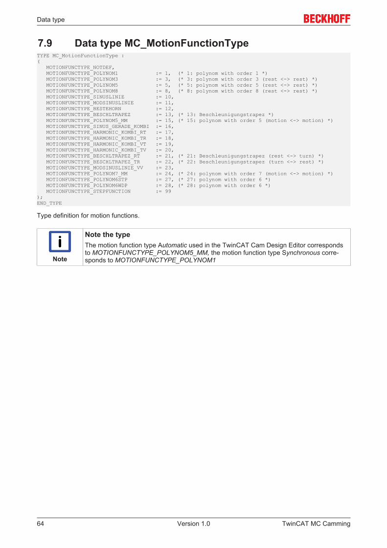
Data type
7.9 Data type MC_MotionFunctionTypeTYPE MC_MotionFunctionType :( MOTIONFUNCTYPE_NOTDEF, MOTIONFUNCTYPE_POLYNOM1 := 1, (* 1: polynom with order 1 *) MOTIONFUNCTYPE_POLYNOM3 := 3, (* 3: polynom with order 3 (rest <-> rest) *) MOTIONFUNCTYPE_POLYNOM5 := 5, (* 5: polynom with order 5 (rest <-> rest) *) MOTIONFUNCTYPE_POLYNOM8 := 8, (* 8: polynom with order 8 (rest <-> rest) *) MOTIONFUNCTYPE_SINUSLINIE := 10, MOTIONFUNCTYPE_MODSINUSLINIE := 11, MOTIONFUNCTYPE_BESTEHORN := 12, MOTIONFUNCTYPE_BESCHLTRAPEZ := 13, (* 13: Beschleunigungstrapez *) MOTIONFUNCTYPE_POLYNOM5_MM := 15, (* 15: polynom with order 5 (motion <-> motion) *) MOTIONFUNCTYPE_SINUS_GERADE_KOMBI := 16, MOTIONFUNCTYPE_HARMONIC_KOMBI_RT := 17, MOTIONFUNCTYPE_HARMONIC_KOMBI_TR := 18, MOTIONFUNCTYPE_HARMONIC_KOMBI_VT := 19, MOTIONFUNCTYPE_HARMONIC_KOMBI_TV := 20, MOTIONFUNCTYPE_BESCHLTRAPEZ_RT := 21, (* 21: Beschleunigungstrapez (rest <-> turn) *) MOTIONFUNCTYPE_BESCHLTRAPEZ_TR := 22, (* 22: Beschleunigungstrapez (turn <-> rest) *) MOTIONFUNCTYPE_MODSINUSLINIE_VV := 23, MOTIONFUNCTYPE_POLYNOM7_MM := 24, (* 24: polynom with order 7 (motion <-> motion) *) MOTIONFUNCTYPE_POLYNOM6STP := 27, (* 27: polynom with order 6 *) MOTIONFUNCTYPE_POLYNOM6WDP := 28, (* 28: polynom with order 6 *) MOTIONFUNCTYPE_STEPFUNCTION := 99);END_TYPE
Type definition for motion functions.
Note
Note the typeThe motion function type Automatic used in the TwinCAT Cam Design Editor correspondsto MOTIONFUNCTYPE_POLYNOM5_MM, the motion function type Synchronous corre-sponds to MOTIONFUNCTYPE_POLYNOM1
TwinCAT MC Camming64 Version 1.0
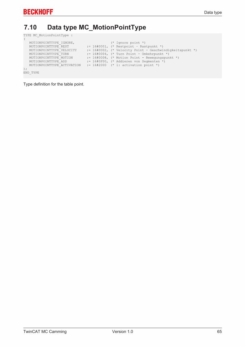
Data type
7.10 Data type MC_MotionPointTypeTYPE MC_MotionPointType :( MOTIONPOINTTYPE_IGNORE, (* Ignore point *) MOTIONPOINTTYPE_REST := 16#0001, (* Restpoint – Rastpunkt *) MOTIONPOINTTYPE_VELOCITY := 16#0002, (* Velocity Point - Geschwindigkeitspunkt *) MOTIONPOINTTYPE_TURN := 16#0004, (* Turn Point - Umkehrpunkt *) MOTIONPOINTTYPE_MOTION := 16#0008, (* Motion Point - Bewegungspunkt *) MOTIONPOINTTYPE_ADD := 16#0F00, (* Addieren von Segmenten *) MOTIONPOINTTYPE_ACTIVATION := 16#2000 (* 1: activation point *));END_TYPE
Type definition for the table point.
TwinCAT MC Camming 65Version 1.0
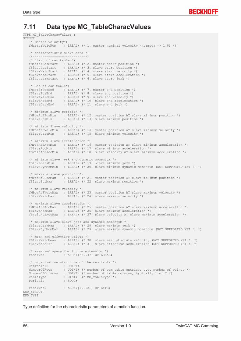
Data type
7.11 Data type MC_TableCharacValuesTYPE MC_TableCharacValues :STRUCT (* Master Velocity*) fMasterVeloNom : LREAL; (* 1. master nominal velocity (normed: => 1.0) *)
(* characteristic slave data *) (*===========================*) (* Start of cam table *) fMasterPosStart : LREAL; (* 2. master start position *) fSlavePosStart : LREAL; (* 3. slave start position *) fSlaveVeloStart : LREAL; (* 4. slave start velocity *) fSlaveAccStart : LREAL; (* 5. slave start acceleration *) fSlaveJerkStart : LREAL; (* 6. slave start jerk *)
(* End of cam table*) fMasterPosEnd : LREAL; (* 7. master end position *) fSlavePosEnd : LREAL; (* 8. slave end position *) fSlaveVeloEnd : LREAL; (* 9. slave end velocity *) fSlaveAccEnd : LREAL; (* 10. slave end acceleration *) fSlaveJerkEnd : LREAL; (* 11. slave end jerk *)
(* minimum slave position *) fMPosAtSPosMin : LREAL; (* 12. master position AT slave minimum position *) fSlavePosMin : LREAL; (* 13. slave minimum position *)
(* minimum Slave velocity *) fMPosAtSVeloMin : LREAL; (* 14. master position AT slave minimum velocity *) fSlaveVeloMin : LREAL; (* 15. slave minimum velocity *)
(* minimum slave acceleration *) fMPosAtSAccMin : LREAL; (* 16. master position AT slave minimum acceleration *) fSlaveAccMin : LREAL; (* 17. slave minimum acceleration *) fSVeloAtSAccMin : LREAL; (* 18. slave velocity AT slave minimum acceleration *)
(* minimum slave jerk and dynamic momentum *) fSlaveJerkMin : LREAL; (* 19. slave minimum jerk *) fSlaveDynMomMin : LREAL; (* 20. slave minimum dynamic momentum (NOT SUPPORTED YET !) *)
(* maximum slave position *) fMPosAtSPosMax : LREAL; (* 21. master position AT slave maximum position *) fSlavePosMax : LREAL; (* 22. slave maximum position *)
(* maximum Slave velocity *) fMPosAtSVeloMax : LREAL; (* 23. master position AT slave maximum velocity *) fSlaveVeloMax : LREAL; (* 24. slave maximum velocity *)
(* maximum slave acceleration *) fMPosAtSAccMax : LREAL; (* 25. master position AT slave maximum acceleration *) fSlaveAccMax : LREAL; (* 26. slave maximum acceleration *) fSVeloAtSAccMax : LREAL; (* 27. slave velocity AT slave maximum acceleration *)
(* maximum Slave slave jerk and dynamic momentum *) fSlaveJerkMax : LREAL; (* 28. slave maximum jerk *) fSlaveDynMomMax : LREAL; (* 29. slave maximum dynamic momentum (NOT SUPPORTED YET !) *)
(* mean and effective values *) fSlaveVeloMean : LREAL; (* 30. slave mean absolute velocity (NOT SUPPORTED YET !) *) fSlaveAccEff : LREAL; (* 31. slave effective acceleration (NOT SUPPORTED YET !) *)
(* reserved space for future extension *) reserved : ARRAY[32..47] OF LREAL;
(* organization structure of the cam table *) CamTableID : UDINT; NumberOfRows : UDINT; (* number of cam table entries, e.g. number of points *) NumberOfColumns : UDINT; (* number of table columns, typically 1 or 2 *) TableType : UINT; (* MC_TableType *) Periodic : BOOL;
reserved2 : ARRAY[1..121] OF BYTE;END_STRUCTEND_TYPE
Type definition for the characteristic parameters of a motion function.
TwinCAT MC Camming66 Version 1.0
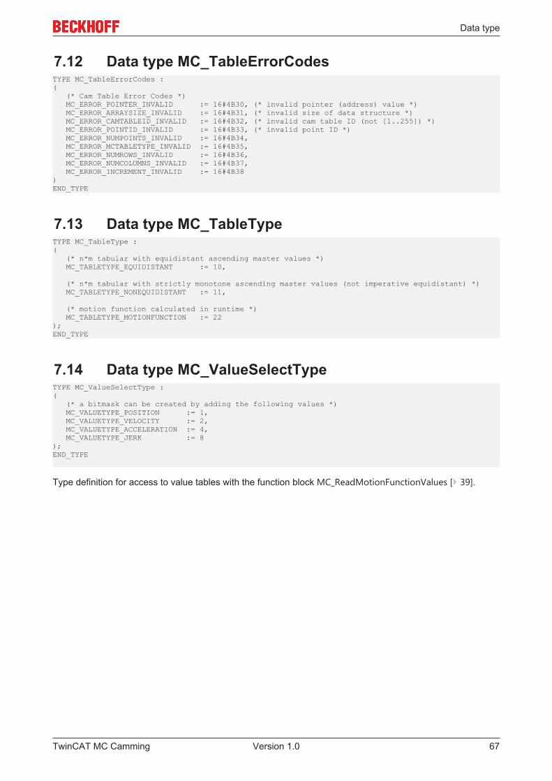
Data type
7.12 Data type MC_TableErrorCodesTYPE MC_TableErrorCodes :( (* Cam Table Error Codes *) MC_ERROR_POINTER_INVALID := 16#4B30, (* invalid pointer (address) value *) MC_ERROR_ARRAYSIZE_INVALID := 16#4B31, (* invalid size of data structure *) MC_ERROR_CAMTABLEID_INVALID := 16#4B32, (* invalid cam table ID (not [1..255]) *) MC_ERROR_POINTID_INVALID := 16#4B33, (* invalid point ID *) MC_ERROR_NUMPOINTS_INVALID := 16#4B34, MC_ERROR_MCTABLETYPE_INVALID := 16#4B35, MC_ERROR_NUMROWS_INVALID := 16#4B36, MC_ERROR_NUMCOLUMNS_INVALID := 16#4B37, MC_ERROR_INCREMENT_INVALID := 16#4B38)END_TYPE
7.13 Data type MC_TableTypeTYPE MC_TableType :( (* n*m tabular with equidistant ascending master values *) MC_TABLETYPE_EQUIDISTANT := 10,
(* n*m tabular with strictly monotone ascending master values (not imperative equidistant) *) MC_TABLETYPE_NONEQUIDISTANT := 11,
(* motion function calculated in runtime *) MC_TABLETYPE_MOTIONFUNCTION := 22);END_TYPE
7.14 Data type MC_ValueSelectTypeTYPE MC_ValueSelectType :( (* a bitmask can be created by adding the following values *) MC_VALUETYPE_POSITION := 1, MC_VALUETYPE_VELOCITY := 2, MC_VALUETYPE_ACCELERATION := 4, MC_VALUETYPE_JERK := 8);END_TYPE
Type definition for access to value tables with the function block MC_ReadMotionFunctionValues [} 39].
TwinCAT MC Camming 67Version 1.0

Data type
7.15 Data type MC_StartModeTYPE MC_StartMode :( MC_STARTMODE_ABSOLUTE := 1, (* cam table is absolute for master and slave *) MC_STARTMODE_RELATIVE := 2, (* cam table is relative for master and slave *) MC_STARTMODE_MASTERABS_SLAVEREL := 3, (* cam table is absolute for master and relative for slave*) MC_STARTMODE_MASTERREL_SLAVEABS := 4 (* cam table is relative for master and absolute for slave*));END_TYPE
StartMode is used for coupling with cam plates through MC_CamIn [} 12] and defines whether a cam plate isinterpreted absolute (based on the origin of the axis coordinate system) or relative to the coupling position.The mode can be specified as absolute or relative separately for both coordinate axes.
With StartModeAbsolut the cam plate coordinate system is congruent with the axis coordinate system andcan be moved through an offset, if required (master or slave offset).
With StartModeRelativ the origin of the cam plate coordinate system is at the axis position of the respectiveaxis (master or slave) at the time of coupling or cam plate switching. The cam plate can additionally bemoved through an offset.
Notice: The modes MC_STARTMODE_RELATIVE and MC_STARTMODE_MASTERREL_SLAVEABScannot be used in conjunction with automatic master offset calculation (MC_CamScalingMode [} 57]), sincethis would cause a conflict.
TwinCAT MC Camming68 Version 1.0
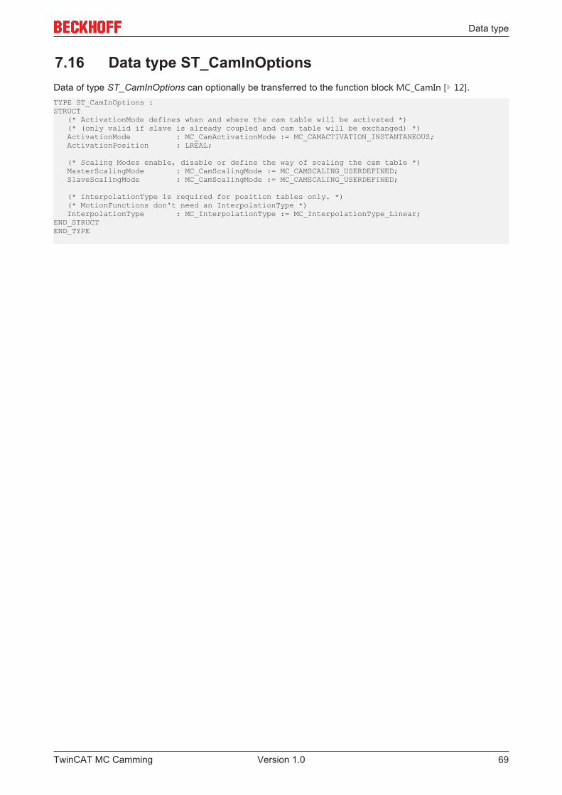
Data type
7.16 Data type ST_CamInOptionsData of type ST_CamInOptions can optionally be transferred to the function block MC_CamIn [} 12].TYPE ST_CamInOptions :STRUCT (* ActivationMode defines when and where the cam table will be activated *) (* (only valid if slave is already coupled and cam table will be exchanged) *) ActivationMode : MC_CamActivationMode := MC_CAMACTIVATION_INSTANTANEOUS; ActivationPosition : LREAL;
(* Scaling Modes enable, disable or define the way of scaling the cam table *) MasterScalingMode : MC_CamScalingMode := MC_CAMSCALING_USERDEFINED; SlaveScalingMode : MC_CamScalingMode := MC_CAMSCALING_USERDEFINED;
(* InterpolationType is required for position tables only. *) (* MotionFunctions don't need an InterpolationType *) InterpolationType : MC_InterpolationType := MC_InterpolationType_Linear;END_STRUCTEND_TYPE
TwinCAT MC Camming 69Version 1.0
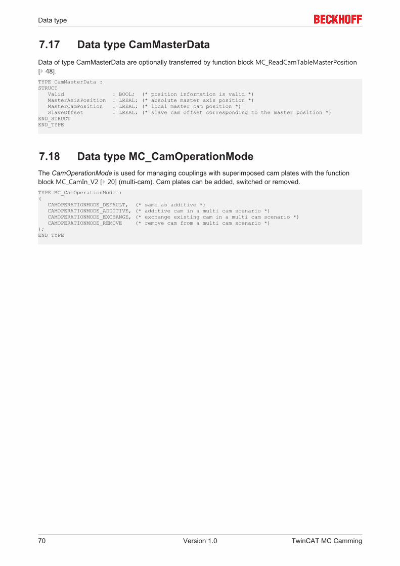
Data type
7.17 Data type CamMasterDataData of type CamMasterData are optionally transferred by function block MC_ReadCamTableMasterPosition[} 48].TYPE CamMasterData :STRUCT Valid : BOOL; (* position information is valid *) MasterAxisPosition : LREAL; (* absolute master axis position *) MasterCamPosition : LREAL; (* local master cam position *) SlaveOffset : LREAL; (* slave cam offset corresponding to the master position *)END_STRUCTEND_TYPE
7.18 Data type MC_CamOperationModeThe CamOperationMode is used for managing couplings with superimposed cam plates with the functionblock MC_CamIn_V2 [} 20] (multi-cam). Cam plates can be added, switched or removed.TYPE MC_CamOperationMode :( CAMOPERATIONMODE_DEFAULT, (* same as additive *) CAMOPERATIONMODE_ADDITIVE, (* additive cam in a multi cam scenario *) CAMOPERATIONMODE_EXCHANGE, (* exchange existing cam in a multi cam scenario *) CAMOPERATIONMODE_REMOVE (* remove cam from a multi cam scenario *));END_TYPE
TwinCAT MC Camming70 Version 1.0
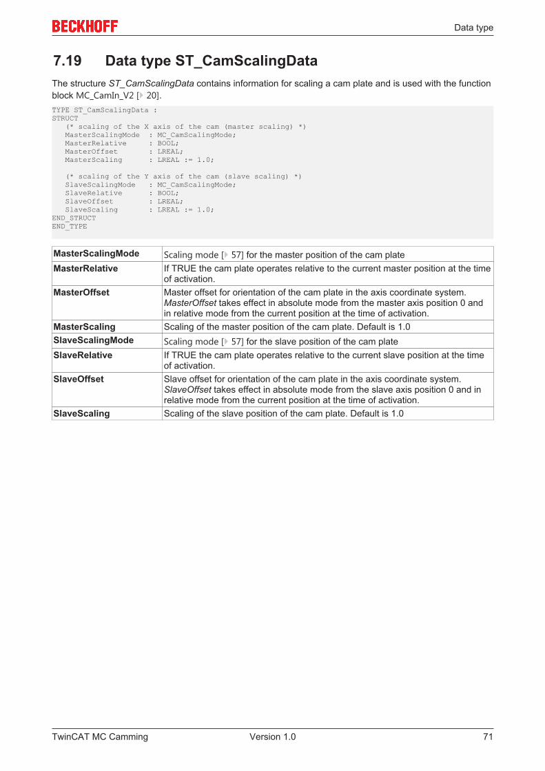
Data type
7.19 Data type ST_CamScalingDataThe structure ST_CamScalingData contains information for scaling a cam plate and is used with the functionblock MC_CamIn_V2 [} 20].TYPE ST_CamScalingData :STRUCT (* scaling of the X axis of the cam (master scaling) *) MasterScalingMode : MC_CamScalingMode; MasterRelative : BOOL; MasterOffset : LREAL; MasterScaling : LREAL := 1.0;
(* scaling of the Y axis of the cam (slave scaling) *) SlaveScalingMode : MC_CamScalingMode; SlaveRelative : BOOL; SlaveOffset : LREAL; SlaveScaling : LREAL := 1.0;END_STRUCTEND_TYPE
MasterScalingMode Scaling mode [} 57] for the master position of the cam plateMasterRelative If TRUE the cam plate operates relative to the current master position at the time
of activation.MasterOffset Master offset for orientation of the cam plate in the axis coordinate system.
MasterOffset takes effect in absolute mode from the master axis position 0 andin relative mode from the current position at the time of activation.
MasterScaling Scaling of the master position of the cam plate. Default is 1.0SlaveScalingMode Scaling mode [} 57] for the slave position of the cam plateSlaveRelative If TRUE the cam plate operates relative to the current slave position at the time
of activation.SlaveOffset Slave offset for orientation of the cam plate in the axis coordinate system.
SlaveOffset takes effect in absolute mode from the slave axis position 0 and inrelative mode from the current position at the time of activation.
SlaveScaling Scaling of the slave position of the cam plate. Default is 1.0
TwinCAT MC Camming 71Version 1.0
Example programs
8 Example programsElectronic Cam TablesThe example program couples a master and a slave axis via cam plates. During the coupled movement camplates are switched, individual sampling points of a cam plate are modified, and the cam plate is scaled.
The example program requires the Tc2_MC2_Camming library and operates fully in simulation mode.Progress can be monitored in the included TwinCAT Measurement project.
Click here to save the example program:
In preparation …
Rotary Knife and RegistrationThe sample uses a rotational knife to cut sheets of a defined length. For this purpose the circumferencespeed must be synchronized with the web while cutting a sheet. The rotation knife must the accelerator ordeceleration since the circumference of the knife is different from the sheet length. Registration marks areused to synchronize with the product. The knife is continuously adjusted to compensate small differencescaused by temperature or stretching.
An electronic cam table is used to synchronize the rotational knife with the material. The cam table is anormalized cam table defined with a length of 360°. The tool moves over a full turn while the cam table isexecuted and the cut position is defined as 0°. The circumference speed is synchronous from 270° to 30°.The range from 30° to 270° is used to adjust the operation to the actual distance of registration marks.
In preparation …
TwinCAT MC Camming72 Version 1.0