Embed Size (px)
Citation preview
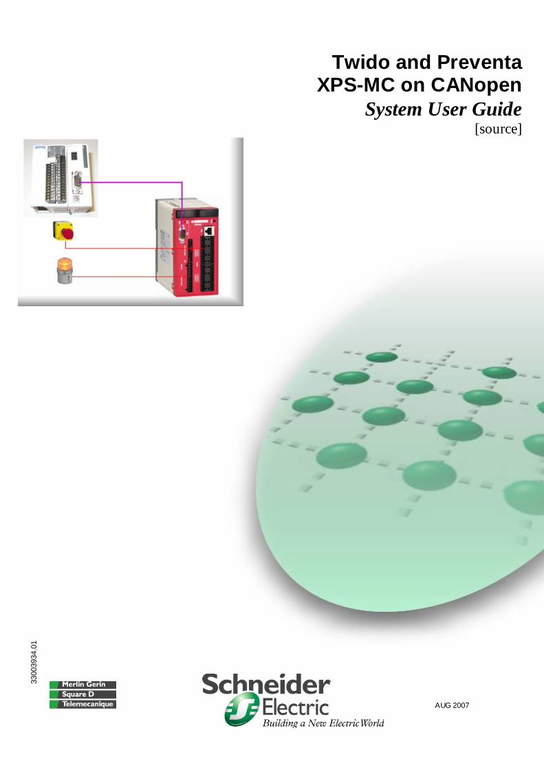
Twido and Preventa XPS-MC on CANopen
System User Guide [source]
3300
3934
.01
AUG 2007
Tw ido and Preventa XPS-MC w ith CANopen_EN.doc
Schneider Electric
2
Contents
Application Source Code ............................................................................................................................ 4 Purpose of the Document ........................................................................................................................... 5 System........................................................................................................................................................... 6
Architecture ........................................................................................................................................... 6 Installation.............................................................................................................................................. 8
Hardware ............................................................................................................................................... 9 Software ...............................................................................................................................................11 Communication ....................................................................................................................................12
Implementation....................................................................................................................................15 Communication ....................................................................................................................................16 Batch File for Preventa .........................................................................................................................18
Batch File Execution........................................................................................................................19 Implementing Twido.............................................................................................................................20
Configuration...................................................................................................................................21 Accessing Objects via an SDO ........................................................................................................32 Explanation of PDO Data .................................................................................................................34
Implementing Preventa Safety Controller.............................................................................................35 Access to Objects via SDO ..............................................................................................................52 Mapping PDO Objects......................................................................................................................53
Appendix..................................................................................................................................................... 54 Detailed Component List.................................................................................................................... 54 Component Protection Classes........................................................................................................ 55 Component Features.......................................................................................................................... 56
Contact ........................................................................................................................................................ 58
Introduction This document is intended to provide a quick introduction to the described System.
It is not intended to replace any specific product documentation. On the contrary, it offers additional information to the product documentation, for installing, configuring and starting up the system. A detailed functional description or the specification for a specific user application is not part of this document. Nevertheless, the document outlines some typical applications where the system might be implemented.
Tw ido and Preventa XPS-MC w ith CANopen_EN.doc
Schneider Electric
3
Abbreviations
Word / Expression Signification AC Alternating Current Advantys SE product name for a family of I/O modules Altivar (ATV) SE product name for a family of VSDs CANopen Name for a communications machine bus system CB Circuit Breaker CoDeSys Hardware-independent IEC 61131-3 programming software ConneXium SE product name for a Family of Transparent Factory devices DI Digital Input DO Digital Output DC Direct Current EDS Electronic Data Sheet ELOP II Factory SE product name for a software configuration tool for Preventa
Safety PLCs E-OFF, E-STOP Emergency Off switch Harmony SE product name for a family of switches and indicators HMI Human Machine Interface I/O Input/Output IclA (ICLA) SE product name for a compact drive Lexium/Lexium05/LXM SE product name for a family of servo-drives Magelis SE product name for a family of HMI-Devices MB - SL SE name for a serial Modbus communications protocol Micro SE product name for a middle range family of PLCs NIM SE product name for a Network Interface Module PC Personal Computer POU Programmable Object Unit, Program Section in CoDeSys and
ELOP II Factory Phaseo SE product name for a family of power supplies PLC Programmable Logic Computer Powersuite An SE software product for configuring ALTIVAR drives Premium SE product name for a middle range family of PLCs Preventa SE product name for a family of safety devices PS1131 (CoDeSys) SE Product name for PLC programming software with CoDeSys PS Power Supply SafetySuite SE product name for a collection of safety software tools SE Schneider Electric Sycon SE product name of a Field bus programming software Telefast SE product name for a series of distributed I/O devices Tesys U SE product name for a decentralized I/O System Twido SE product name of a middle range family of PLCs TwidoSoft SE product name for a PLC programming software Unity (Pro) SE product name for a PLC programming software Vijeo Designer An SE software product for programming Magelis HMI devices VSD Variable Speed Drive WxHxD Dimensions : Width, Height and Depth XBT-L1000 An SE software product for programming Magelis HMI devices
Tw ido and Preventa XPS-MC w ith CANopen_EN.doc
Schneider Electric
4
Application Source Code
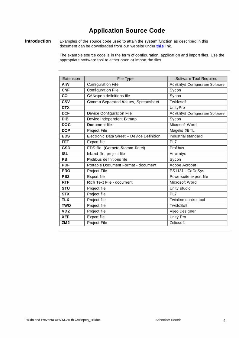
Introduction Examples of the source code used to attain the system function as described in this document can be downloaded from our website under this link. The example source code is in the form of configuration, application and import files. Use the appropriate software tool to either open or import the files.
Extension File Type Software Tool Required AIW Configuration File Advantys Configuration Software CNF Configuration File Sycon CO CANopen definitions file Sycon CSV Comma Separated Values, Spreadsheet Twidosoft CTX UnityPro DCF Device Configuration File Advantys Configuration Software DIB Device Independent Bitmap Sycon DOC Document file Microsoft Word DOP Project File Magelis XBTL EDS Electronic Data Sheet – Device Definition Industrial standard FEF Export file PL7 GSD EDS file (Geraete Stamm Datei) Profibus ISL Island file, project file Advantys PB Profibus definitions file Sycon PDF Portable Document Format - document Adobe Acrobat PRO Project File PS1131 - CoDeSys PS2 Export file Powersuite export file RTF Rich Text File - document Microsoft Word STU Project file Unity studio STX Project file PL7 TLX Project file Twinline control tool TWD Project file TwidoSoft VDZ Project file Vijeo Designer XEF Export file Unity Pro ZM2 Project File Zeliosoft
Tw ido and Preventa XPS-MC w ith CANopen_EN.doc
Schneider Electric
5
Purpose of the Document
Introduction This document describes all the necessary steps to configure a Twido PLC with a
Preventa safety controller using CANopen. At the heart of this process is the CANopen connection. The document provides a brief introduction to the special features and CANopen performance characteristics of the Twido and Preventa safety controller. Configuring the Preventa safety controller for CANopen on the Twido is extremely easy, as a special file is provided for this purpose. The file replaces much of the configuration work by pre-configuring the Twido CANopen master. For TwidoSuite you can download the file XPSMC1632ZC for TwidoSuite.exe. The configuration of the Preventa XPS-MCxxZC controller is done using the XPSMCWIN configuration software and merely entails configuring the safety equipment.
Tw ido and Preventa XPS-MC w ith CANopen_EN.doc
Schneider Electric
6
System
Introduction The system chapter describes the architecture, the dimensions, the quantities and different
types of components used within this system.
Architecture
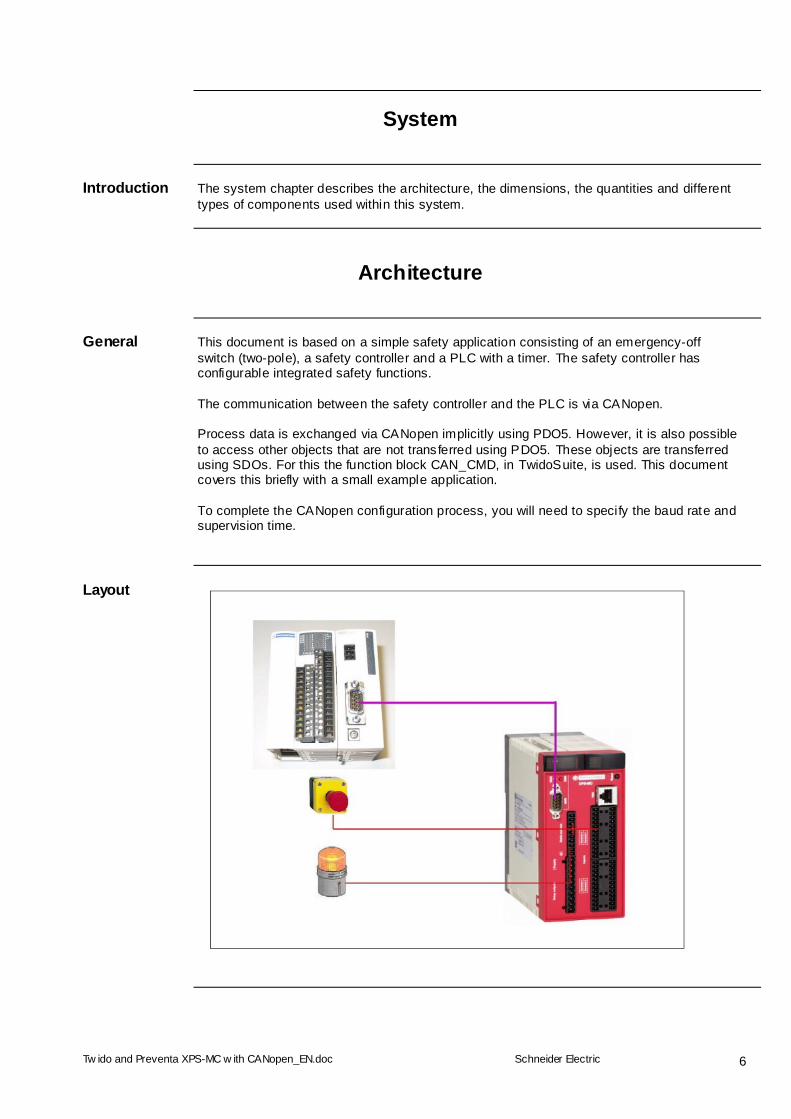
General This document is based on a simple safety application consisting of an emergency-off
switch (two-pole), a safety controller and a PLC with a timer. The safety controller has configurable integrated safety functions. The communication between the safety controller and the PLC is via CANopen. Process data is exchanged via CANopen implicitly using PDO5. However, it is also possible to access other objects that are not transferred using PDO5. These objects are transferred using SDOs. For this the function block CAN_CMD, in TwidoSuite, is used. This document covers this briefly with a small example application. To complete the CANopen configuration process, you will need to specify the baud rate and supervision time.
Layout
Tw ido and Preventa XPS-MC w ith CANopen_EN.doc
Schneider Electric
7
Components Hardware:
Twido Modular PLC with 12 DI and 8 DO CANopen Master Module for Twido Preventa Safety Controller with 32 DI Harmony Series 5 Switch (E-OFF and acknowledgement) Harmony signal light Phaseo power supply 24V
Software:
TwidoSuite V 1.03 XPSMCWIN V 2.10 SafetySuite V 2.0
Quantities of Components
For a complete and detailed list of components, the quantities required and the order numbers, please refer to the components list at the rear of this document.
Degree of Protection
Not all the components in this configuration are designed to withstand the same environmental conditions. Some components may need additional protection, in the form of housings, depending on the environment in which you intend to use them. For environmental details of the individual components please refer to the list in the appendix of this document and the appropriate user manual.
Mains voltage 24V DC Safety Level Cat. 3
Technical Data
Note: The application described here is only intended as a simple example of how to use the safety components of the Twido PLC and the Preventa safety controller
Safety Notice The standard and level of safety you apply to your application is determined by your
system design and the overall extent to which your system may be a hazard to people and machinery. As there are no moving mechanical parts in this application example, category 3 (according to EN954-1) has been selected as an optional safety level. Whether or not the above safety category should be applied to your system should be ascertained with a proper risk analysis. This document is not comprehensive for any systems using the given architecture and does not absolve users of their duty to uphold the safety requirements with respect to the equipment used in their systems or of compliance with either national or international safety laws and regulations
Dimensions No dimensions of the system size are given in this document as the example described
here is a mere component for a larger system.
Tw ido and Preventa XPS-MC w ith CANopen_EN.doc
Schneider Electric
8
Installation
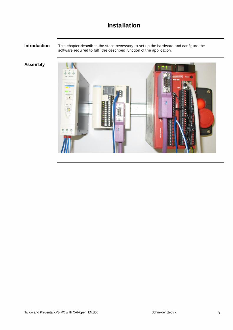
Introduction This chapter describes the steps necessary to set up the hardware and configure the
software required to fulfil the described function of the application.
Assembly
Tw ido and Preventa XPS-MC w ith CANopen_EN.doc
Schneider Electric
9
Hardware
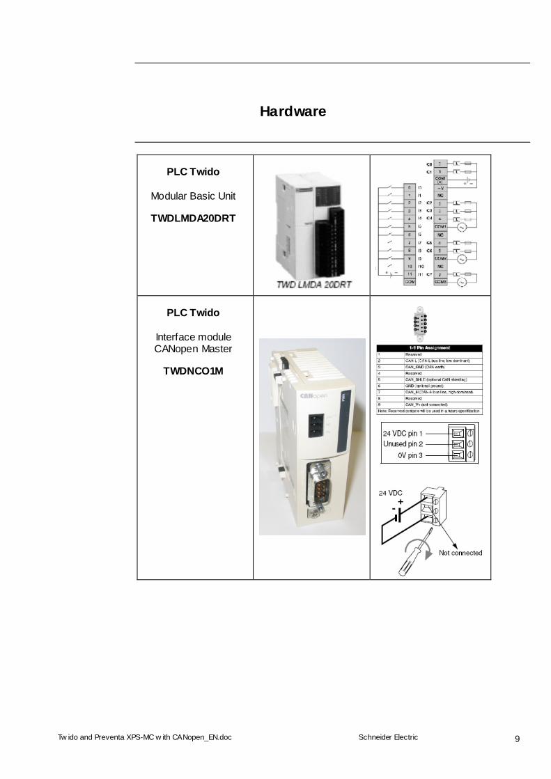
PLC Twido
Modular Basic Unit
TWDLMDA20DRT
PLC Twido
Interface module CANopen Master
TWDNCO1M
Tw ido and Preventa XPS-MC w ith CANopen_EN.doc
Schneider Electric
10
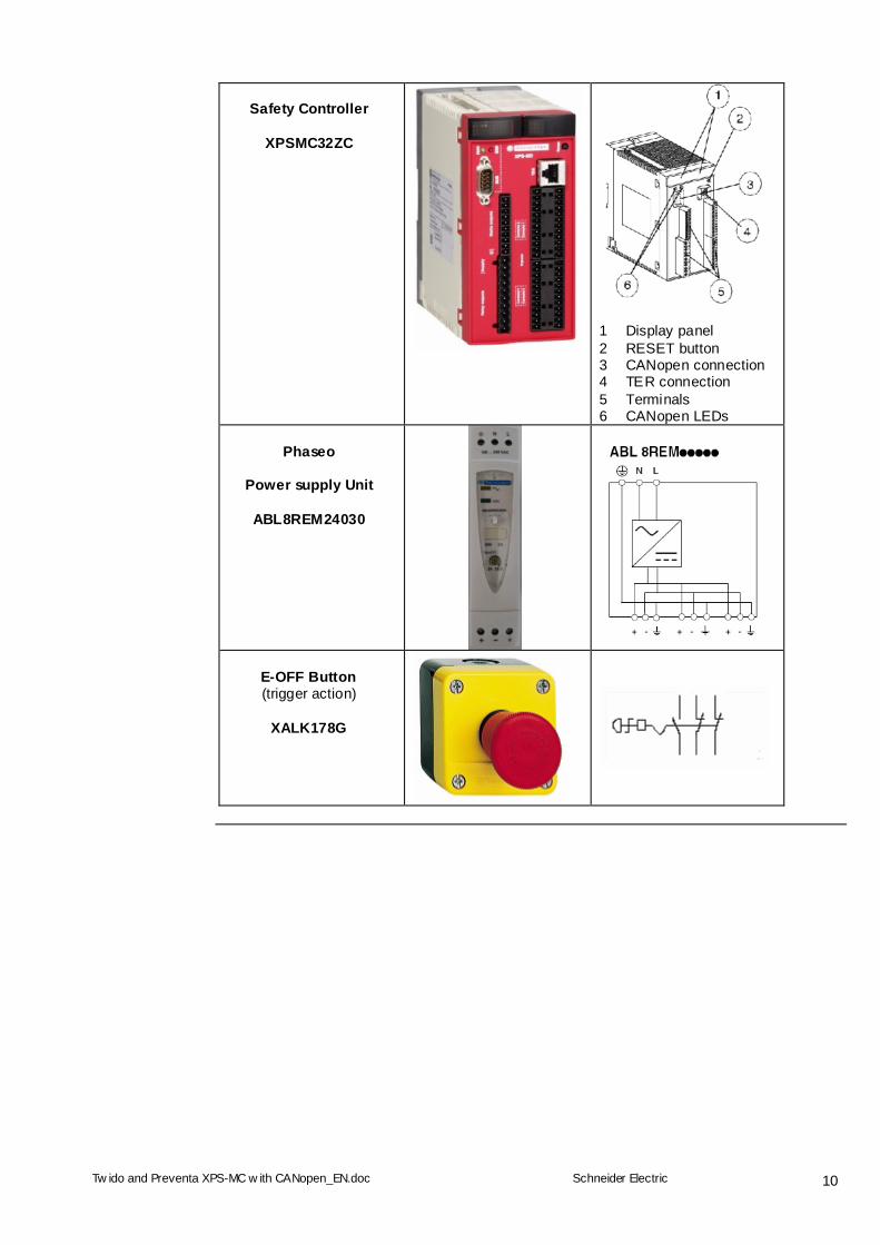
Safety Controller
XPSMC32ZC
1 Display panel 2 RESET button 3 CANopen connection 4 TER connection 5 Terminals 6 CANopen LEDs
Phaseo
Power supply Unit
ABL8REM24030
E-OFF Button (trigger action)
XALK178G
Tw ido and Preventa XPS-MC w ith CANopen_EN.doc
Schneider Electric
11
Software
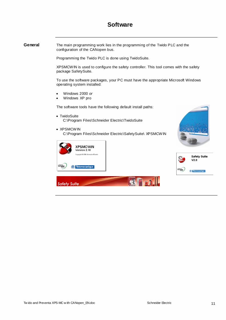
General The main programming work lies in the programming of the Twido PLC and the
configuration of the CANopen bus. Programming the Twido PLC is done using TwidoSuite. XPSMCWIN is used to configure the safety controller. This tool comes with the safety package SafetySuite. To use the software packages, your PC must have the appropriate Microsoft Windows operating system installed: Windows 2000 or Windows XP pro
The software tools have the following default install paths: TwidoSuite C:\Program Files\Schneider Electric\TwidoSuite XPSMCWIN C:\Program Files\Schneider Electric\SafetySuite\ XPSMCWIN
Tw ido and Preventa XPS-MC w ith CANopen_EN.doc
Schneider Electric
12
Communication
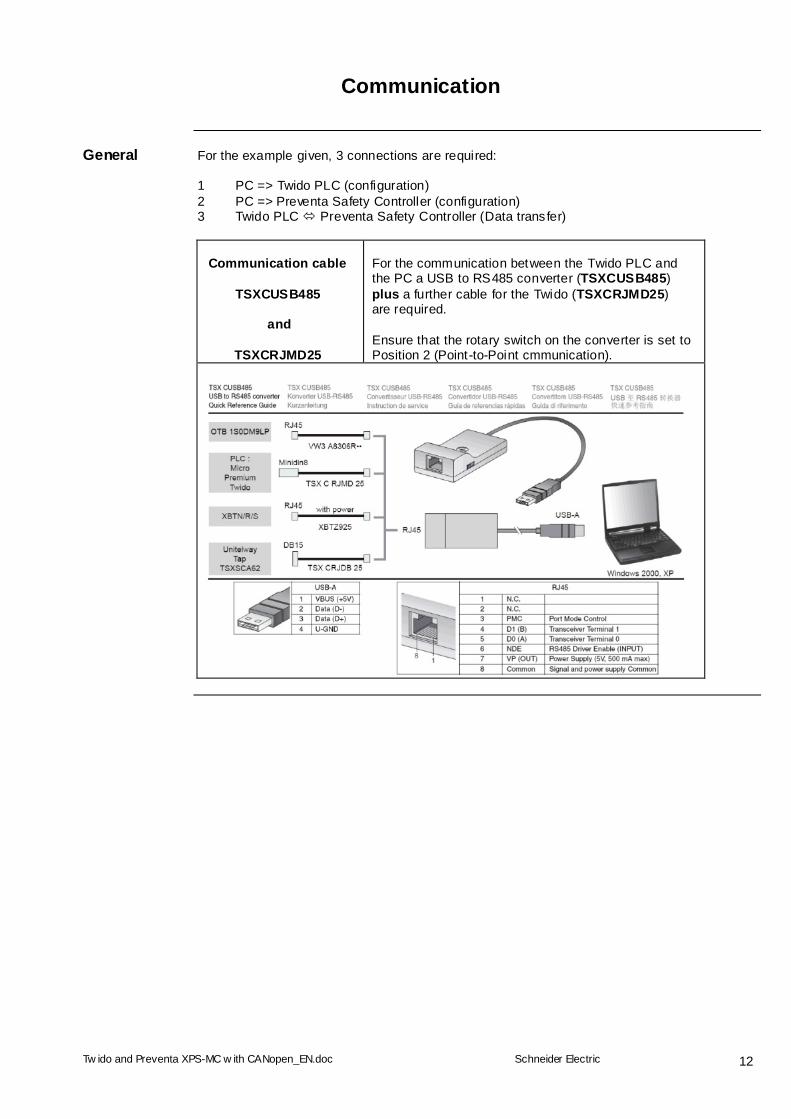
General For the example given, 3 connections are required:
1 PC => Twido PLC (configuration) 2 PC => Preventa Safety Controller (configuration) 3 Twido PLC Preventa Safety Controller (Data transfer)
Communication cable
TSXCUSB485
and
TSXCRJMD25
For the communication between the Twido PLC and the PC a USB to RS485 converter (TSXCUSB485) plus a further cable for the Twido (TSXCRJMD25) are required. Ensure that the rotary switch on the converter is set to Position 2 (Point-to-Point cmmunication).

Tw ido and Preventa XPS-MC w ith CANopen_EN.doc
Schneider Electric
13
Preventa
Safety Controller
Programming cable TSXCUSB485
and TSXCRJMD25
plus Adapter XPSMCCPC
Note: The rotary switch on the adapter TSXCUSB485 must be set to Position 3 (OTHER DIRECT).
Tw ido and Preventa XPS-MC w ith CANopen_EN.doc
Schneider Electric
14
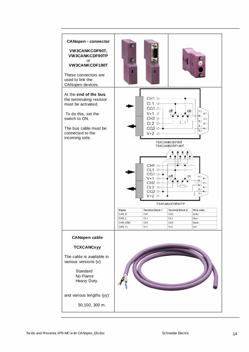
CANopen - connector
VW3CANKCDF90T, VW3CANKCDF90TP
or VW3CANKCDF180T
These connectors are used to link the CANopen devices.
At the end of the bus, the terminating resistor must be activated. To do this, set the switch to ON. The bus cable must be connected to the incoming side.
CANopen cable
TCXCANCxyy
The cable is available in various versions (x):
Standard No Flame Heavy Duty
and various lengths (yy):
50,100, 300 m.
Tw ido and Preventa XPS-MC w ith CANopen_EN.doc
Schneider Electric
15
Implementation
Introduction The implementation chapter describes all the steps necessary to initialise, to configure, to
program and start-up the system to achieve the application functions as listed below.
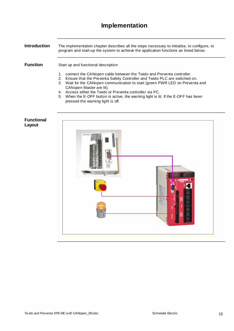
Function
Start up and functional description 1. connect the CANopen cable between the Twido and Preventa controller. 2. Ensure that the Preventa Safety Controller and Twido PLC are switched on. 3. Wait for the CANopen communication to start (green PWR LED on Preventa and
CANopen Master are lit). 4. Access either the Twido or Preventa controller via PC. 5. When the E-OFF button is active, the warning light is lit. If the E-OFF has been
pressed the warning light is off.
Functional Layout
Tw ido and Preventa XPS-MC w ith CANopen_EN.doc
Schneider Electric
16
Communication
Introduction This chapter describes the data passed via the communications bus (CANopen)
that is not bound directly with digital or analog hardware. The list contains:
The device links Direction of data flow symbolic name and Bus address of the device concerned.
Device Links The CANopen bus system is used in this application.
The following devices are networked via CANopen: - A Twido PLC, bus address 127 (fixed) - A Preventa safety controller, bus address 1
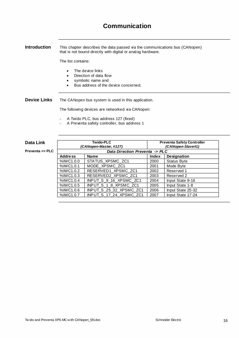
Data Link Twido-PLC
(CANopen-Master, #127) Preventa Safety Controller
(CANopen-Slave#1) Preventa <> PLC Data Direction Preventa -> PLC Address Name Index Designation %IWC1.0.0 STATUS_XPSMC_ZC1 2000 Status Byte %IWC1.0.1 MODE_XPSMC_ZC1 2001 Mode Byte %IWC1.0.2 RESERVED1_XPSMC_ZC1 2002 Reserved 1 %IWC1.0.3 RESERVED2_XPSMC_ZC1 2003 Reserved 2 %IWC1.0.4 INPUT_S_9_16_XPSMC_ZC1 2004 Input State 9-16 %IWC1.0.5 INPUT_S_1_8_XPSMC_ZC1 2005 Input State 1-8 %IWC1.0.6 INPUT_S_25_32_XPSMC_ZC1 2006 Input State 25-32 %IWC1.0.7 INPUT_S_17_24_XPSMC_ZC1 2007 Input State 17-24
Tw ido and Preventa XPS-MC w ith CANopen_EN.doc
Schneider Electric
17
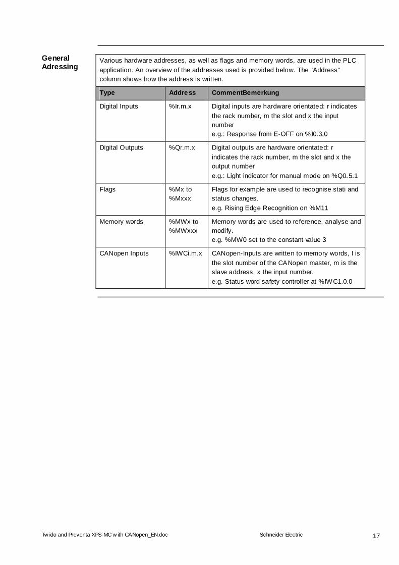
Various hardware addresses, as well as flags and memory words, are used in the PLC application. An overview of the addresses used is provided below. The "Address" column shows how the address is written.
Type Address CommentBemerkung
Digital Inputs %Ir.m.x Digital inputs are hardware orientated: r indicates the rack number, m the slot and x the input number e.g.: Response from E-OFF on %I0.3.0
Digital Outputs %Qr.m.x Digital outputs are hardware orientated: r indicates the rack number, m the slot and x the output number e.g.: Light indicator for manual mode on %Q0.5.1
Flags %Mx to %Mxxx
Flags for example are used to recognise stati and status changes. e.g. Rising Edge Recognition on %M11
Memory words %MWx to %MWxxx
Memory words are used to reference, analyse and modify. e.g. %MW0 set to the constant value 3
General Adressing
CANopen Inputs %IWCi.m.x CANopen-Inputs are written to memory words, I is the slot number of the CANopen master, m is the slave address, x the input number. e.g. Status word safety controller at %IWC1.0.0
Tw ido and Preventa XPS-MC w ith CANopen_EN.doc
Schneider Electric
18
Batch File for Preventa
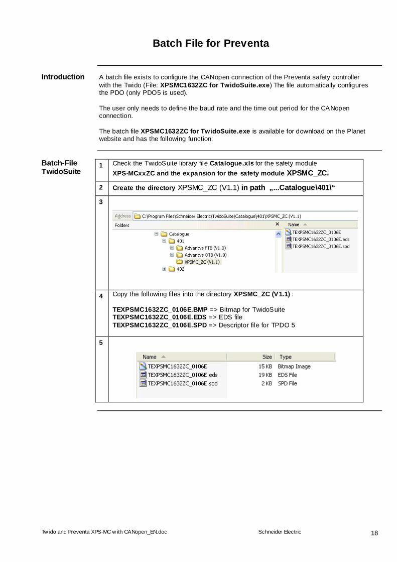
Introduction A batch file exists to configure the CANopen connection of the Preventa safety controller
with the Twido (File: XPSMC1632ZC for TwidoSuite.exe) The file automatically configures the PDO (only PDO5 is used). The user only needs to define the baud rate and the time out period for the CANopen connection. The batch file XPSMC1632ZC for TwidoSuite.exe is available for download on the Planet website and has the following function:
Batch-File TwidoSuite
1 Check the TwidoSuite library file Catalogue.xls for the safety module XPS-MCxxZC and the expansion for the safety module XPSMC_ZC.
2 Create the directory XPSMC_ZC (V1.1) in path „...Catalogue\401\“
3
4 Copy the following files into the directory XPSMC_ZC (V1.1) : TEXPSMC1632ZC_0106E.BMP => Bitmap for TwidoSuite TEXPSMC1632ZC_0106E.EDS => EDS file TEXPSMC1632ZC_0106E.SPD => Descriptor file for TPDO 5
5

Tw ido and Preventa XPS-MC w ith CANopen_EN.doc
Schneider Electric
19
Symbolic Names
1 When the batch file Twidosuite.exe is invoked, the PDO5 mapped objects (all of type byte) are automatically given symbolic names which are described in the file TEXPSMC1632ZC_0106E.SPD (Format: *.XML) .
note:
In TwidoSuite all PDO5 objects of type byte are actually stored in words.
2
Event-Timer 1 The desriptor file TEXPSMC1632ZC_0106E.SPD sets the Event-Timer to 200 ms
and activates PDO5.
Batch File Execution
Integrating the Safety Controller in TwidoSuite
1 Unpack the attached ZIP file: TwidoSuite.zip
2 Integrating the Preventa safety controller, XPS-MC, in TwidoSuite is done by invoking the batch file XPSMC1632ZC for TwidoSuite.exe.
3 You are asked to confirm the install path.
4 After installation you are informed
of its successful completion You can now use the Preventa safety controller in all future Twido projects.
Tw ido and Preventa XPS-MC w ith CANopen_EN.doc
Schneider Electric
20
Implementing Twido
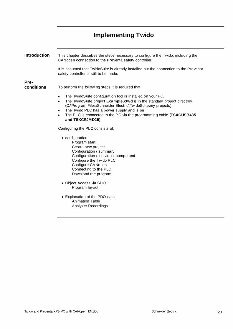
Introduction This chapter describes the steps necessary to configure the Twido, including the
CANopen connection to the Preventa safety controller. It is assumed that TwidoSuite is already installed but the connection to the Preventa safety controller is still to be made.
Pre-conditions
To perform the following steps it is required that: The TwidoSuite configuration tool is installed on your PC. The TwidoSuite project Example.xtwd is in the standard project directory.
(C:\Program Files\Schneider Electric\TwidoSuite\my projects) The Twido PLC has a power supply and is on The PLC is connected to the PC via the programming cable (TSXCUSB485
and TSXCRJMD25) Configuring the PLC consists of: configuration
Program start Create new project Configuration / summary Configuration / individual component Configure the Twido PLC Configure CANopen Connecting to the PLC Download the program
Object Access via SDO Program layout
Explanation of the PDO data Animation Table Analyzer Recordings
Tw ido and Preventa XPS-MC w ith CANopen_EN.doc
Schneider Electric
21
Configuration
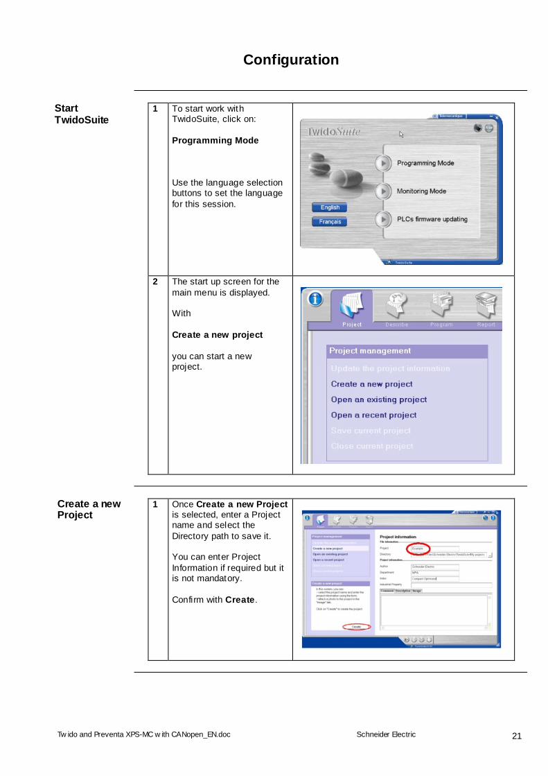
Start TwidoSuite
1 To start work with TwidoSuite, click on: Programming Mode Use the language selection buttons to set the language for this session.
2 The start up screen for the main menu is displayed. With Create a new project you can start a new project.
Create a new Project
1 Once Create a new Project is selected, enter a Project name and select the Directory path to save it. You can enter Project Information if required but it is not mandatory. Confirm with Create.

Tw ido and Preventa XPS-MC w ith CANopen_EN.doc
Schneider Electric
22
Select the Hardware
1 Now go to Describe to configure the hardware.
2 In the configuration Workspace you will see a Twido PLC. In the Catalog on the RHS you can select the hardware/modules you wish to configure The Workspace offers you graphical documentation.
3 In the Catalog, first select the correct type of Twido TWDLMDA20DRT.
Tw ido and Preventa XPS-MC w ith CANopen_EN.doc
Schneider Electric
23
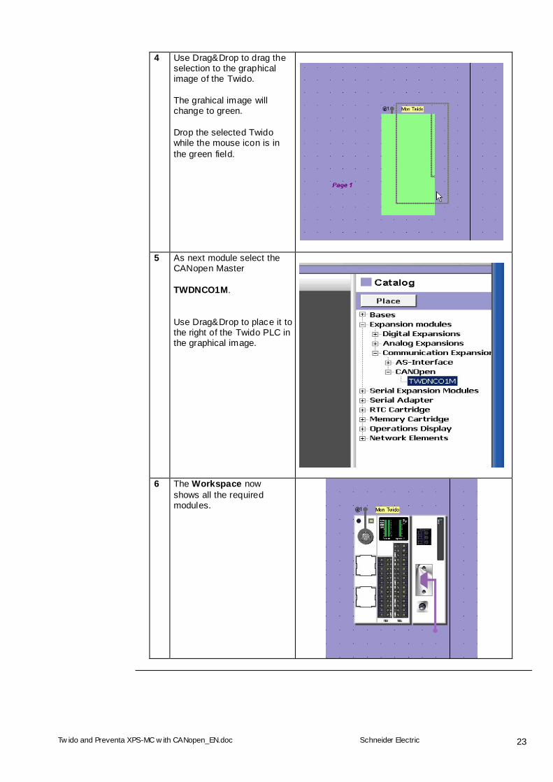
4 Use Drag&Drop to drag the selection to the graphical image of the Twido. The grahical image will change to green. Drop the selected Twido while the mouse icon is in the green field.
5 As next module select the CANopen Master TWDNCO1M. Use Drag&Drop to place it to the right of the Twido PLC in the graphical image.
6 The Workspace now shows all the required modules.
Tw ido and Preventa XPS-MC w ith CANopen_EN.doc
Schneider Electric
24
Configure the Hardware
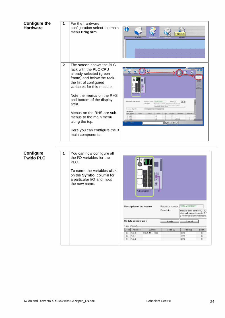
1 For the hardware configuration select the main menu Program.
2 The screen shows the PLC rack with the PLC CPU already selected (green frame) and below the rack the list of configured variables for this module. Note the menus on the RHS and bottom of the display area. Menus on the RHS are sub-menus to the main menu along the top. Here you can configure the 3 main components.
Configure Twido PLC
1 You can now configure all the I/O variables for the PLC. To name the variables click on the Symbol column for a particular I/O and input the new name.
Tw ido and Preventa XPS-MC w ith CANopen_EN.doc
Schneider Electric
25
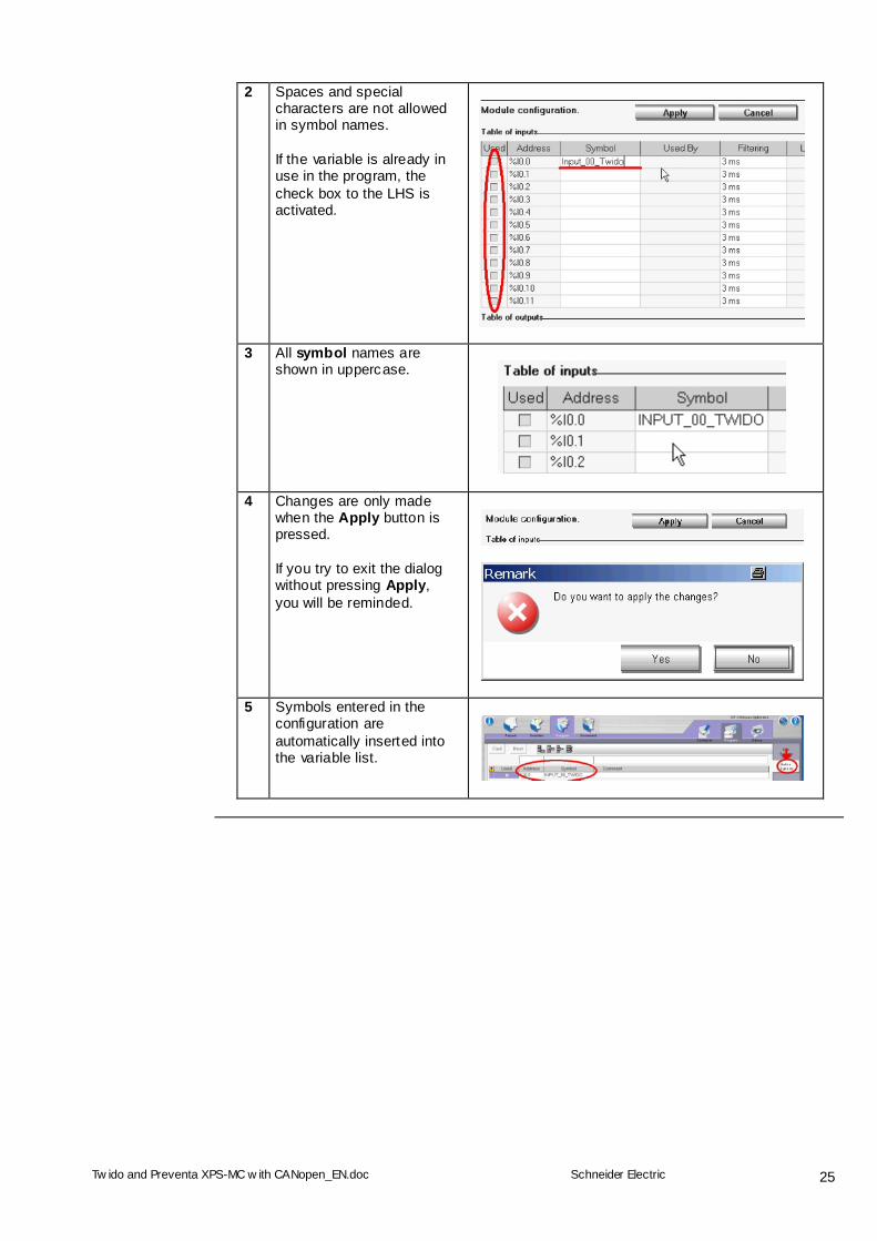
2 Spaces and special characters are not allowed in symbol names. If the variable is already in use in the program, the check box to the LHS is activated.
3 All symbol names are shown in uppercase.
4 Changes are only made when the Apply button is pressed. If you try to exit the dialog without pressing Apply, you will be reminded.
5 Symbols entered in the configuration are automatically inserted into the variable list.

Tw ido and Preventa XPS-MC w ith CANopen_EN.doc
Schneider Electric
26
Configure CANopen Master
1 Now configure the CANopen Master. Click on the CANopen module in the graphics display.
2 Click on Configure in the module configuration.
3 Select the tab Network. The catalogue contains the CANopen profiles for DS401 and DS402.
4 A double click on the arrow
icon before the entry in the catalogue displays the CANopen device. The Preventa safety controller XPS-MC is already listed (click on the „+“ symbol) as it was added by the batch file XPSMC1632ZC for TwidoSuite.exe
Tw ido and Preventa XPS-MC w ith CANopen_EN.doc
Schneider Electric
27
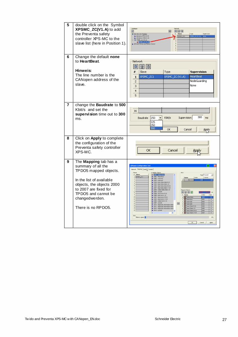
5 double click on the Symbol XPSMC_ZC(V1.A) to add the Preventa safety controller XPS-MC to the slave list (here in Position 1).
6 Change the default none to HeartBeat. Hinweis: The line number is the CANopen address of the slave.
7 change the Baudrate to 500 Kbit/s and set the supervision time out to 300 ms.
8 Click on Apply to complete the configuration of the Preventa safety controller XPS-MC.
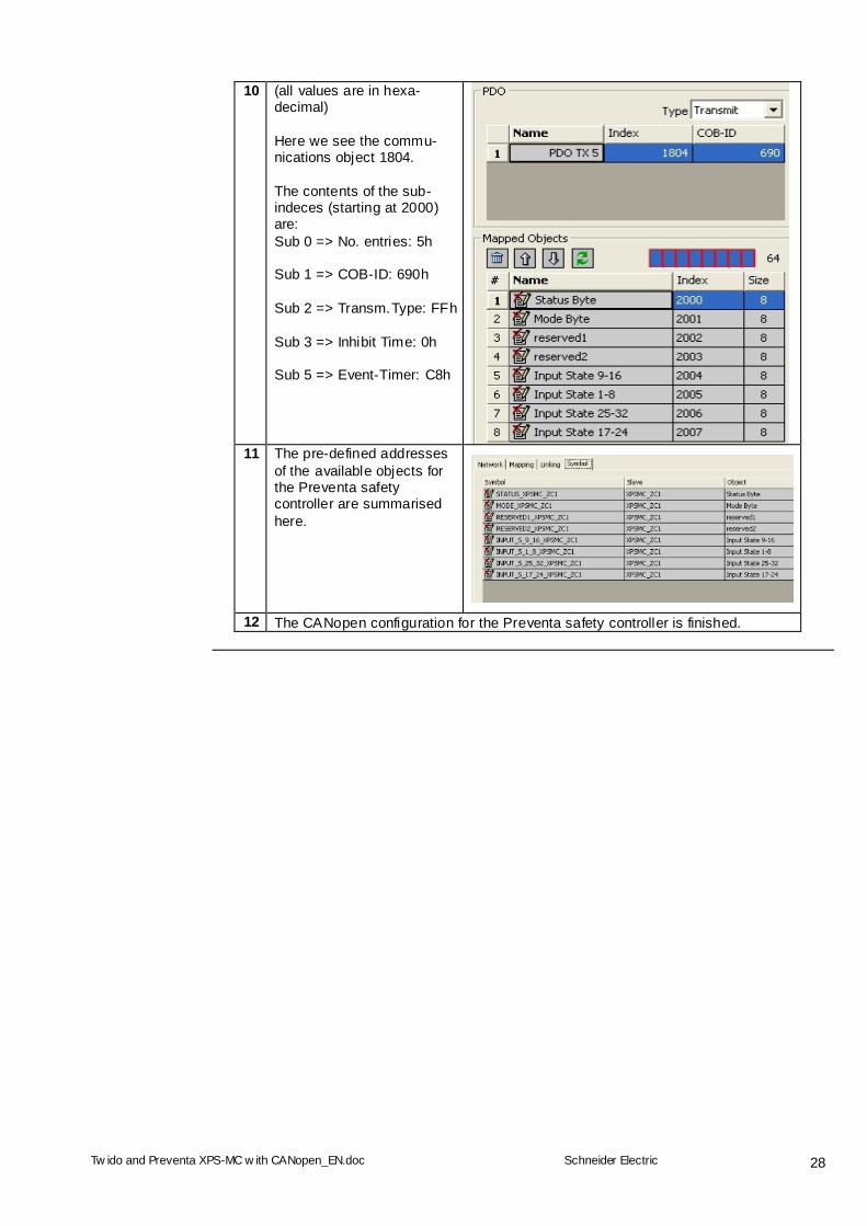
9 The Mapping tab has a summary of all the TPDO5 mapped objects. In the list of available objects, the objects 2000 to 2007 are fixed for TPDO5 and cannot be changedwerden. There is no RPDO5.
Tw ido and Preventa XPS-MC w ith CANopen_EN.doc
Schneider Electric
28
10 (all values are in hexa-decimal) Here we see the commu-nications object 1804. The contents of the sub-indeces (starting at 2000) are: Sub 0 => No. entries: 5h Sub 1 => COB-ID: 690h Sub 2 => Transm.Type: FFh Sub 3 => Inhibit Time: 0h Sub 5 => Event-Timer: C8h
11 The pre-defined addresses
of the available objects for the Preventa safety controller are summarised here.
12 The CANopen configuration for the Preventa safety controller is finished.

Tw ido and Preventa XPS-MC w ith CANopen_EN.doc
Schneider Electric
29
Connecting to the PLC
1 To connect the PC to the PLC select Program in the main menu, then Debug in the sub-menu to get access to the connect selection.
2 You can now either configure a new connection (see the menu at bottom of the window) or select a pre-configured connection. To connect click on OK.
3 You will be shown a progress bar while TwidoSuite establishes the connection.
Download Program
1 After successfully connecting to the Twido, TwidoSuite compares the status of the project and the Twido PLC. Now you can either download your project or upload the contents of the PLC.
2 To download the project select: Transfer PC->controller and confirm with OK
Tw ido and Preventa XPS-MC w ith CANopen_EN.doc
Schneider Electric
30
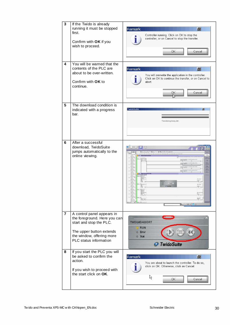
3 If the Twido is already running it must be stopped first. Confirm with OK if you wish to proceed.
4 You will be warned that the contents of the PLC are about to be over-written. Confirm with OK to continue.
5 The download condition is indicated with a progress bar.
6 After a successful download, TwidoSuite jumps automatically to the online viewing.
7 A control panel appears in the foreground. Here you can start and stop the PLC. The upper button extends the window, offering more PLC status information
8 If you start the PLC you will
be asked to confirm the action. If you wish to proceed with the start click on OK.
Tw ido and Preventa XPS-MC w ith CANopen_EN.doc
Schneider Electric
31
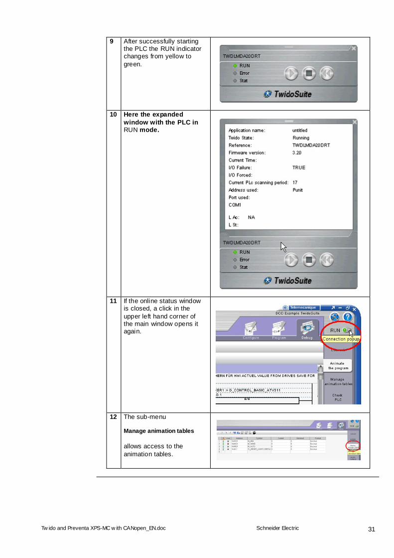
9 After successfully starting the PLC the RUN indicator changes from yellow to green.
10 Here the expanded window with the PLC in RUN mode.
11 If the online status window is closed, a click in the upper left hand corner of the main window opens it again.
12 The sub-menu Manage animation tables allows access to the animation tables.
Tw ido and Preventa XPS-MC w ith CANopen_EN.doc
Schneider Electric
32
Accessing Objects via an SDO
Reading Objects via an SDO
The following illustration of how XPS-MC Preventa safety controller objects can be accessed explicitly is based on the example of Object 2008, Sub-index 0 used in conjunction with the “CAN_CMD1” TwidoSuite function block.
Program Structure
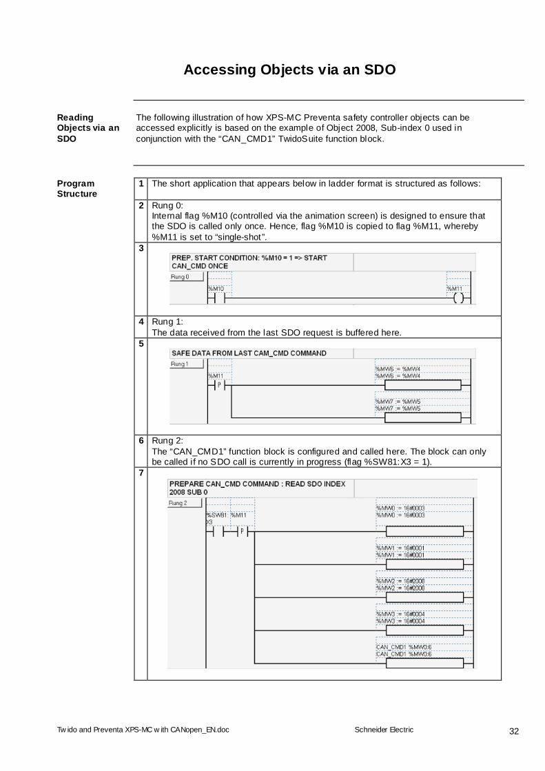
1 The short application that appears below in ladder format is structured as follows:
2 Rung 0: Internal flag %M10 (controlled via the animation screen) is designed to ensure that the SDO is called only once. Hence, flag %M10 is copied to flag %M11, whereby %M11 is set to “single-shot”.
3
4 Rung 1: The data received from the last SDO request is buffered here.
5
6 Rung 2: The “CAN_CMD1” function block is configured and called here. The block can only be called if no SDO call is currently in progress (flag %SW81:X3 = 1).
7
Tw ido and Preventa XPS-MC w ith CANopen_EN.doc
Schneider Electric
33
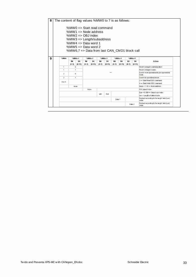
8 The content of flag values %MW0 to 7 is as follows:
%MW0 => Start read command %MW1 => Node address %MW2 => OBJ index %MW3 => Length/subaddress %MW4 => Data word 1 %MW5 => Data word 2 %MW6,7 => Data from last CAN_CMD1 block call
9
Tw ido and Preventa XPS-MC w ith CANopen_EN.doc
Schneider Electric
34
Explanation of PDO Data
General
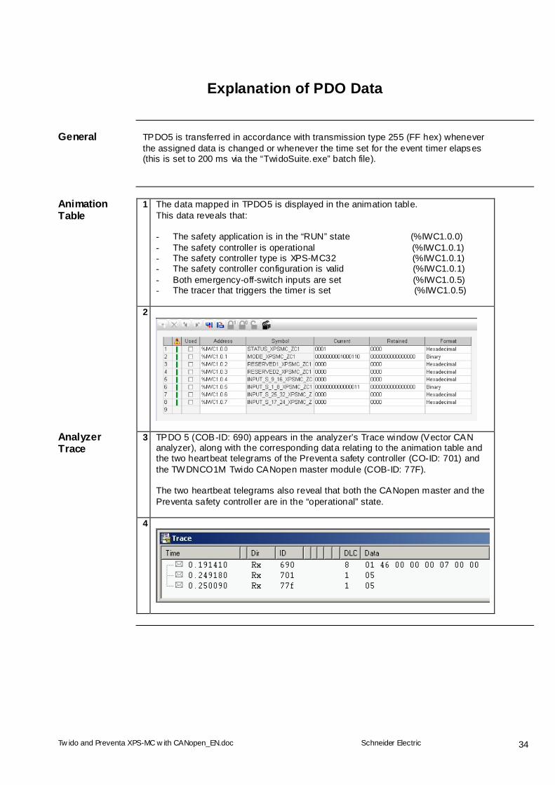
TPDO5 is transferred in accordance with transmission type 255 (FF hex) whenever the assigned data is changed or whenever the time set for the event timer elapses (this is set to 200 ms via the “TwidoSuite.exe” batch file).
Animation Table
1 The data mapped in TPDO5 is displayed in the animation table. This data reveals that: - The safety application is in the “RUN” state (%IWC1.0.0) - The safety controller is operational (%IWC1.0.1) - The safety controller type is XPS-MC32 (%IWC1.0.1) - The safety controller configuration is valid (%IWC1.0.1) - Both emergency-off-switch inputs are set (%IWC1.0.5) - The tracer that triggers the timer is set (%IWC1.0.5)
2
Analyzer Trace
3 TPDO 5 (COB-ID: 690) appears in the analyzer’s Trace window (Vector CAN analyzer), along with the corresponding data relating to the animation table and the two heartbeat telegrams of the Preventa safety controller (CO-ID: 701) and the TWDNCO1M Twido CANopen master module (COB-ID: 77F). The two heartbeat telegrams also reveal that both the CANopen master and the Preventa safety controller are in the “operational” state.
4
Tw ido and Preventa XPS-MC w ith CANopen_EN.doc
Schneider Electric
35
Implementing Preventa Safety Controller
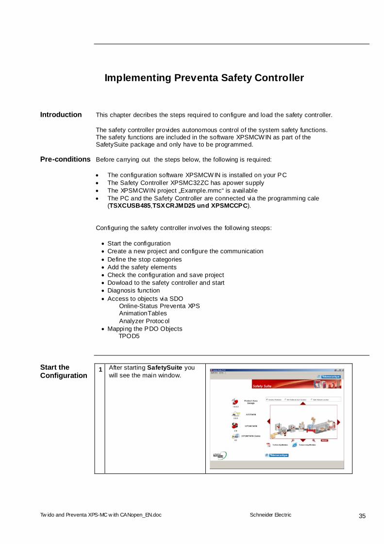
Introduction This chapter decribes the steps required to configure and load the safety controller.
The safety controller provides autonomous control of the system safety functions. The safety functions are included in the software XPSMCWIN as part of the SafetySuite package and only have to be programmed.
Pre-conditions Before carrying out the steps below, the following is required: The configuration software XPSMCWIN is installed on your PC The Safety Controller XPSMC32ZC has apower supply The XPSMCWIN project „Example.mmc“ is available The PC and the Safety Controller are connected via the programming cale
(TSXCUSB485,TSXCRJMD25 und XPSMCCPC). Configuring the safety controller involves the following steops: Start the configuration Create a new project and configure the communication Define the stop categories Add the safety elements Check the configuration and save project Dowload to the safety controller and start Diagnosis function Access to objects via SDO
Online-Status Preventa XPS AnimationTables Analyzer Protocol
Mapping the PDO Objects TPOD5
Start the Configuration
1 After starting SafetySuite you will see the main window.
Tw ido and Preventa XPS-MC w ith CANopen_EN.doc
Schneider Electric
36
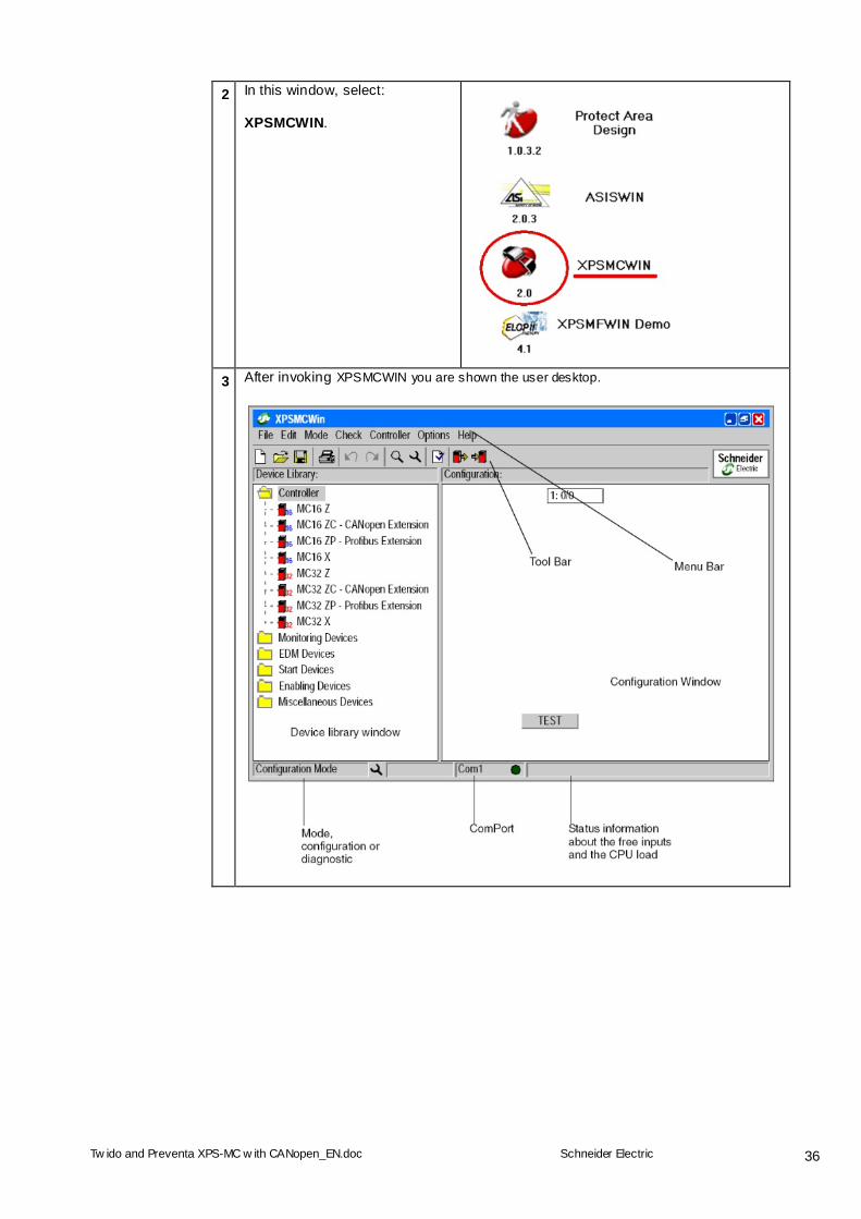
2 In this window, select: XPSMCWIN.
3 After invoking XPSMCWIN you are shown the user desktop.
Tw ido and Preventa XPS-MC w ith CANopen_EN.doc
Schneider Electric
37
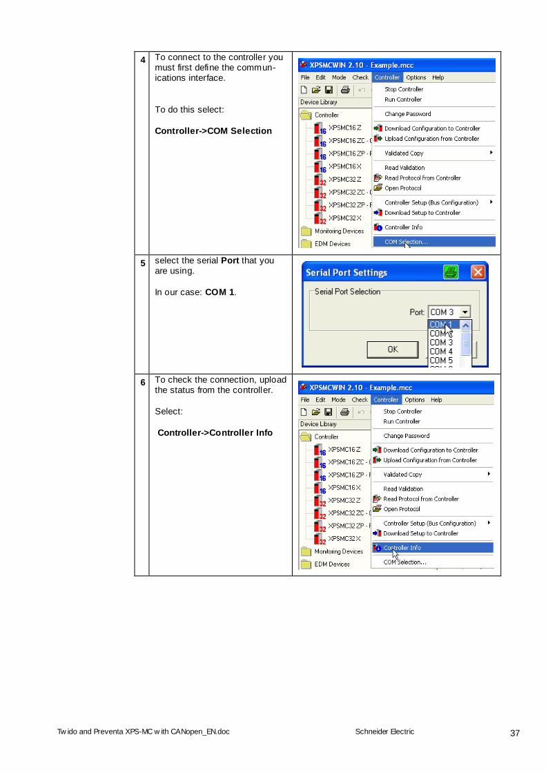
4 To connect to the controller you must first define the commun-ications interface. To do this select: Controller->COM Selection
5 select the serial Port that you are using. In our case: COM 1.
6 To check the connection, upload the status from the controller. Select: Controller->Controller Info
Tw ido and Preventa XPS-MC w ith CANopen_EN.doc
Schneider Electric
38
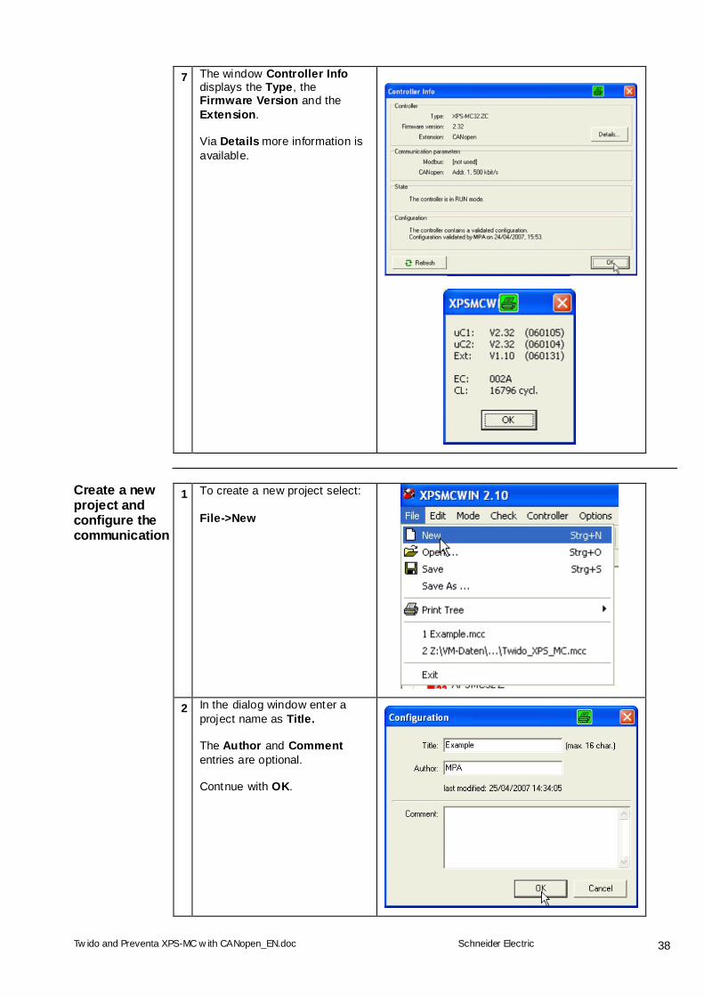
7 The window Controller Info displays the Type, the Firmware Version and the Extension. Via Details more information is available.
Create a new project and configure the communication
1 To create a new project select: File->New
2 In the dialog window enter a project name as Title. The Author and Comment entries are optional. Contnue with OK.
Tw ido and Preventa XPS-MC w ith CANopen_EN.doc
Schneider Electric
39
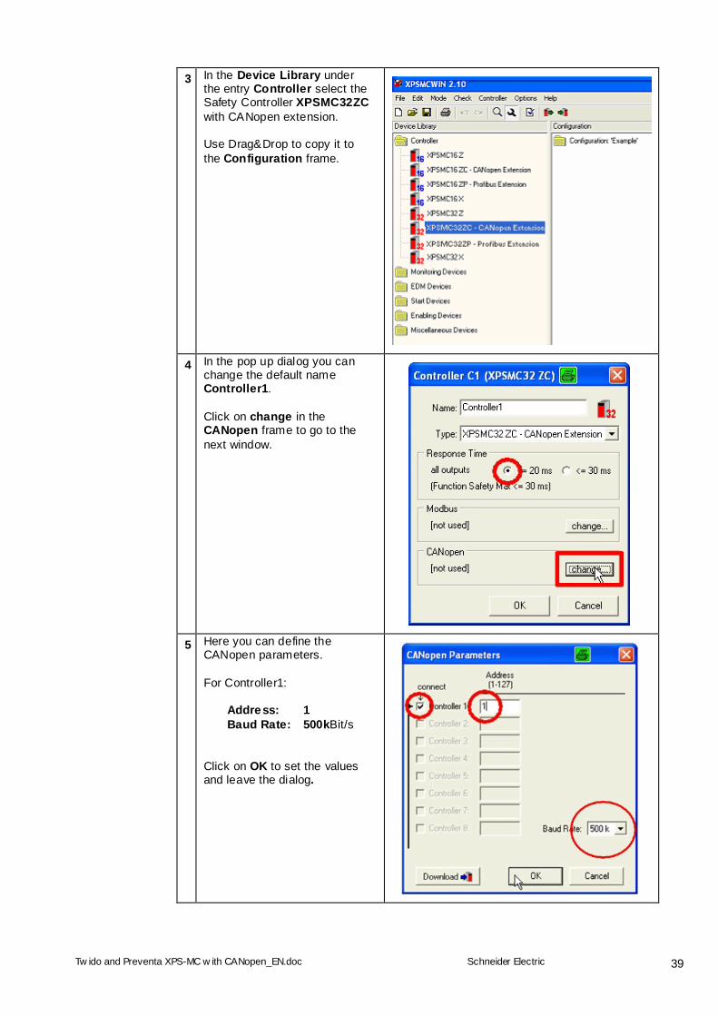
3 In the Device Library under the entry Controller select the Safety Controller XPSMC32ZC with CANopen extension. Use Drag&Drop to copy it to the Configuration frame.
4 In the pop up dialog you can change the default name Controller1. Click on change in the CANopen frame to go to the next window.
5 Here you can define the CANopen parameters. For Controller1: Address: 1 Baud Rate: 500kBit/s Click on OK to set the values and leave the dialog.
Tw ido and Preventa XPS-MC w ith CANopen_EN.doc
Schneider Electric
40
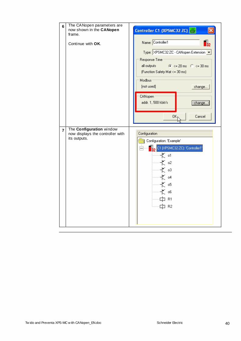
6 The CANopen parameters are now shown in the CANopen frame. Continue with OK.
7 The Configuration window now displays the controller with its outputs.
Tw ido and Preventa XPS-MC w ith CANopen_EN.doc
Schneider Electric
41
Define the Stop Categories
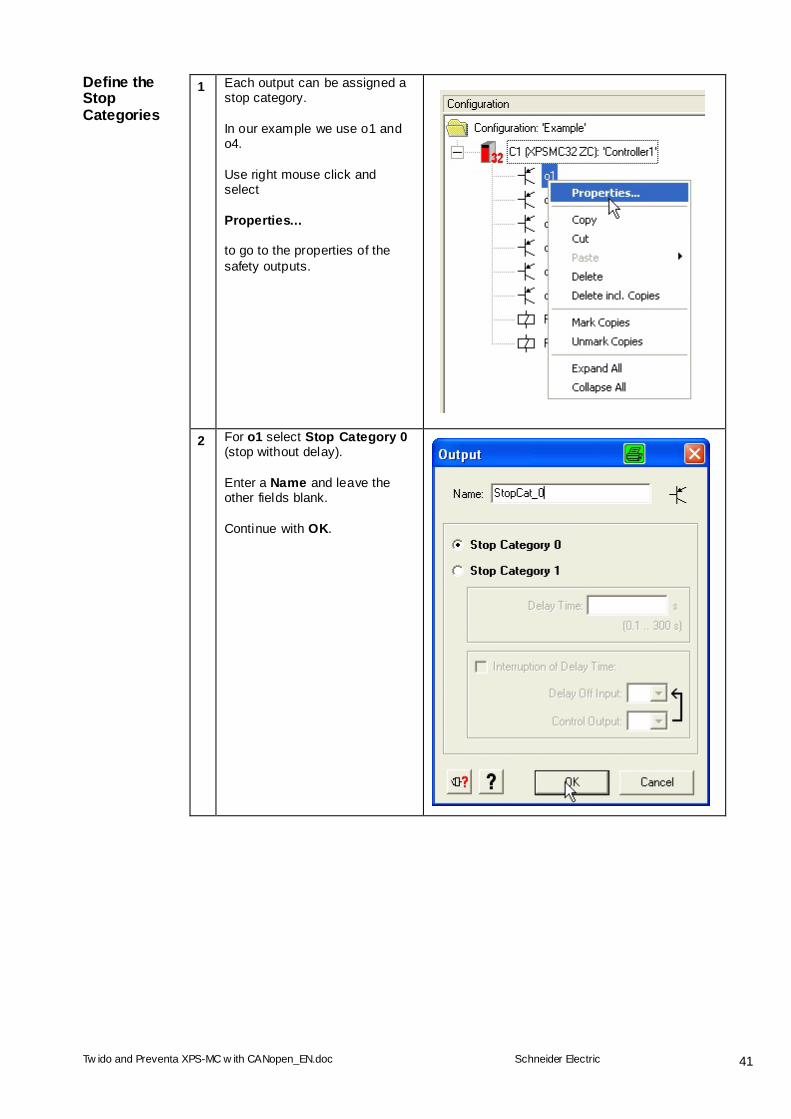
1 Each output can be assigned a stop category. In our example we use o1 and o4. Use right mouse click and select Properties… to go to the properties of the safety outputs.
2 For o1 select Stop Category 0 (stop without delay). Enter a Name and leave the other fields blank. Continue with OK.
Tw ido and Preventa XPS-MC w ith CANopen_EN.doc
Schneider Electric
42
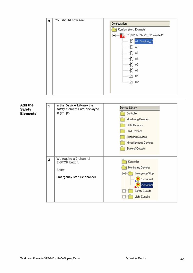
3 You should now see:
Add the Safety Elements
1 In the Device Library the safety elements are displayed in groups.
2 We require a 2-channel E-STOP button. Select Emergency Stop->2-channel ….
Tw ido and Preventa XPS-MC w ith CANopen_EN.doc
Schneider Electric
43
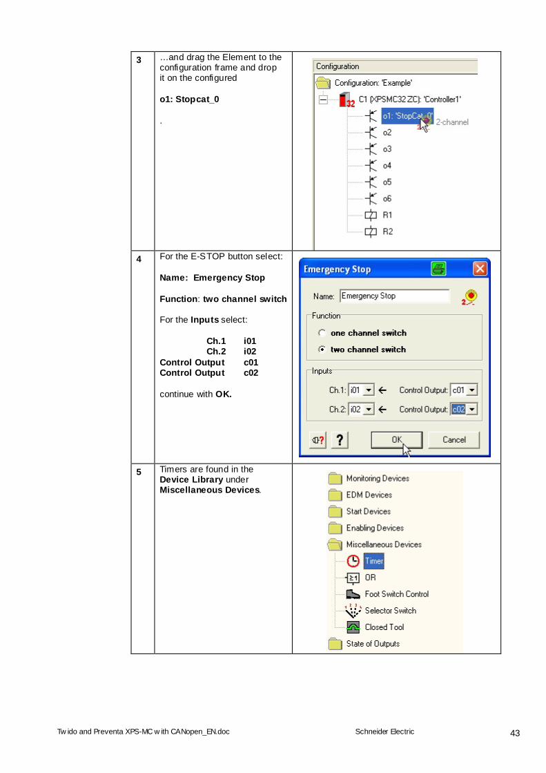
3 …and drag the Element to the configuration frame and drop it on the configured o1: Stopcat_0 .
4 For the E-STOP button select:
Name: Emergency Stop Function: two channel switch For the Inputs select: Ch.1 i01 Ch.2 i02 Control Output c01 Control Output c02 continue with OK.
5 Timers are found in the Device Library under Miscellaneous Devices.
Tw ido and Preventa XPS-MC w ith CANopen_EN.doc
Schneider Electric
44
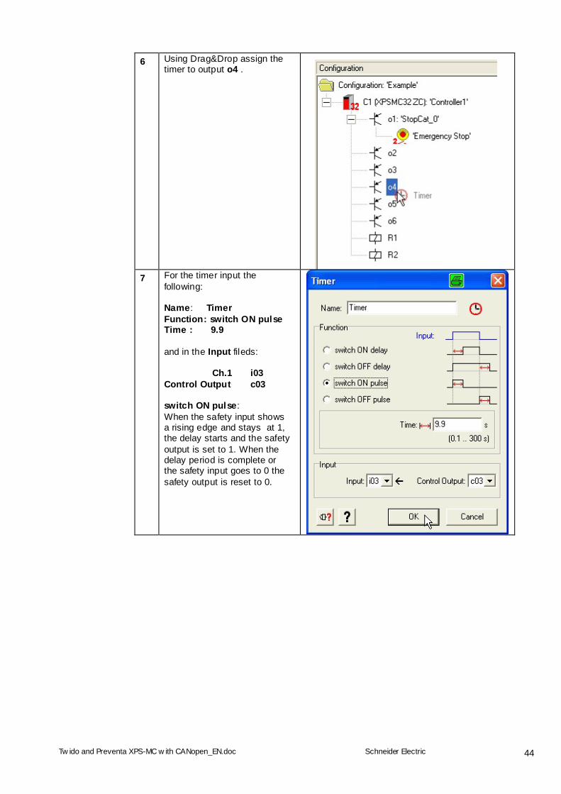
6 Using Drag&Drop assign the timer to output o4 .
7 For the timer input the
following: Name: Timer Function: switch ON pulse Time : 9.9 and in the Input fileds: Ch.1 i03 Control Output c03 switch ON pulse: When the safety input shows a rising edge and stays at 1, the delay starts and the safety output is set to 1. When the delay period is complete or the safety input goes to 0 the safety output is reset to 0.
Tw ido and Preventa XPS-MC w ith CANopen_EN.doc
Schneider Electric
45
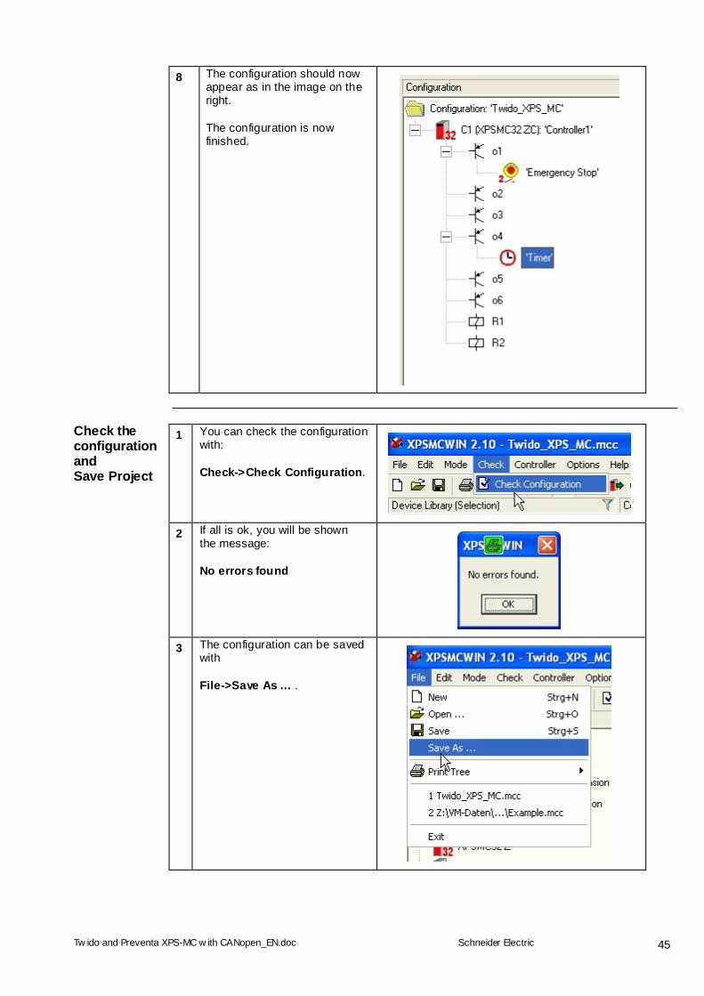
8 The configuration should now appear as in the image on the right. The configuration is now finished.
Check the configurationand Save Project
1 You can check the configuration with: Check->Check Configuration.
2 If all is ok, you will be shown the message: No errors found
3 The configuration can be saved with File->Save As … .
Tw ido and Preventa XPS-MC w ith CANopen_EN.doc
Schneider Electric
46
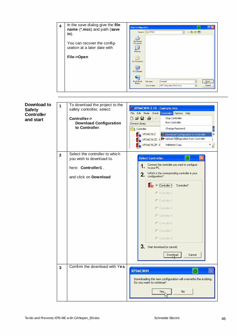
4 In the save dialog give the file name (*.mcc) and path (save in). You can recover the config-uration at a later date with File->Open
Download to Safety Controller and start
1 To download the project to the safety controller, select: Controller-> Download Configuration to Controller.
2 Select the controller to which you wish to download to. here: Controller1 . and click on Download
3 Confirm the download with Yes.
Tw ido and Preventa XPS-MC w ith CANopen_EN.doc
Schneider Electric
47
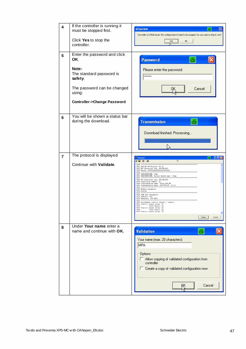
4 If the controller is running it must be stopped first. Click Yes to stop the controller.
5 Enter the password and click OK. Note: The standard password is safety. The password can be changed using: Controller->Change Password
6 You will be shown a status bar during the download.
7 The protocol is displayed Continue with Validate.
8 Under Your name enter a name and continue with OK.
Tw ido and Preventa XPS-MC w ith CANopen_EN.doc
Schneider Electric
48
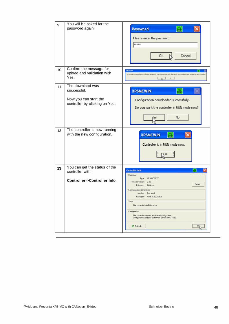
9 You will be asked for the password again.
10 Confirm the message for upload and validation with Yes.
11 The downlaod was successful. Now you can start the controller by clicking on Yes.
12 The controller is now running with the new configuration.
13 You can get the status of the controller with: Controller->Controller Info.
Tw ido and Preventa XPS-MC w ith CANopen_EN.doc
Schneider Electric
49
Diagnosis Function
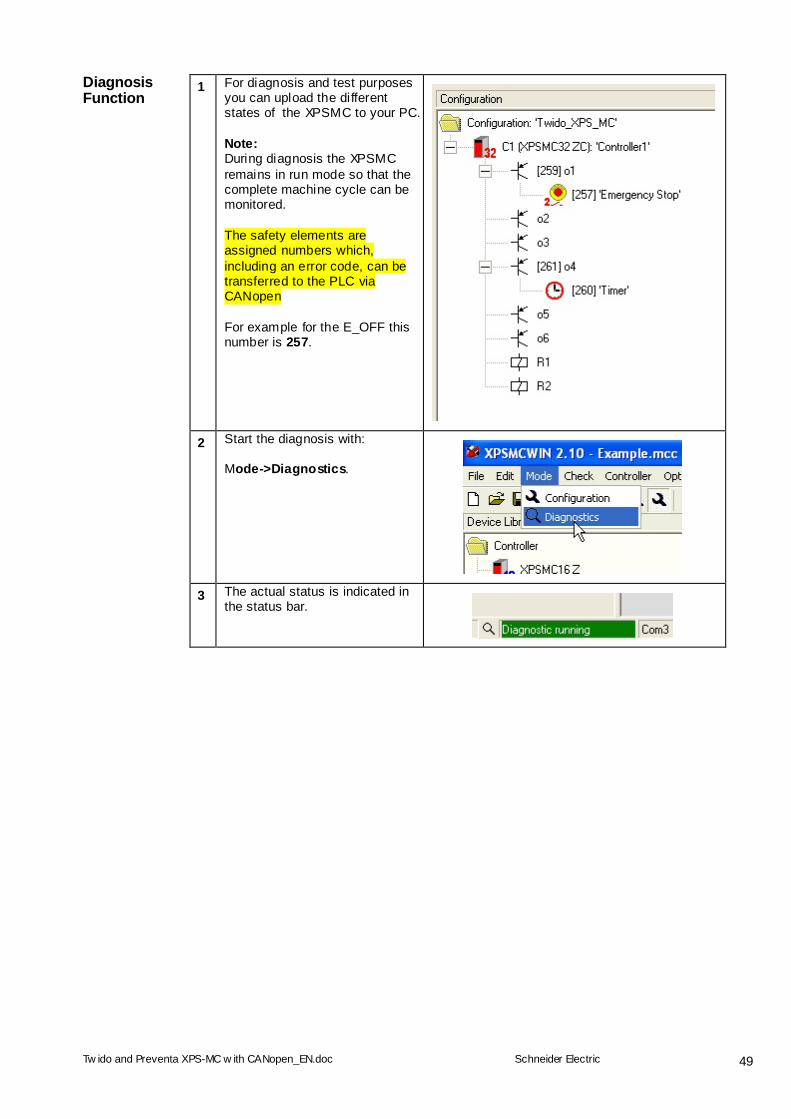
1 For diagnosis and test purposes you can upload the different states of the XPSMC to your PC. Note: During diagnosis the XPSMC remains in run mode so that the complete machine cycle can be monitored. The safety elements are assigned numbers which, including an error code, can be transferred to the PLC via CANopen For example for the E_OFF this number is 257.
2 Start the diagnosis with: Mode->Diagnostics.
3 The actual status is indicated in the status bar.
Tw ido and Preventa XPS-MC w ith CANopen_EN.doc
Schneider Electric
50
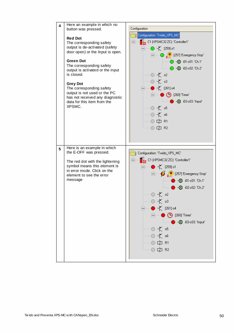
4 Here an example in which no button was pressed. Red Dot The corresponding safety output is de-activated (safety door open) or the Input is open. Green Dot The corresponding safety output is activated or the input is closed. Grey Dot The corresponding safety output is not used or the PC has not received any diagnostic data for this item from the XPSMC.
5 Here is an example in which the E-OFF was pressed. The red dot with the lightening symbol means this element is in error mode. Click on the element to see the error message
Tw ido and Preventa XPS-MC w ith CANopen_EN.doc
Schneider Electric
51
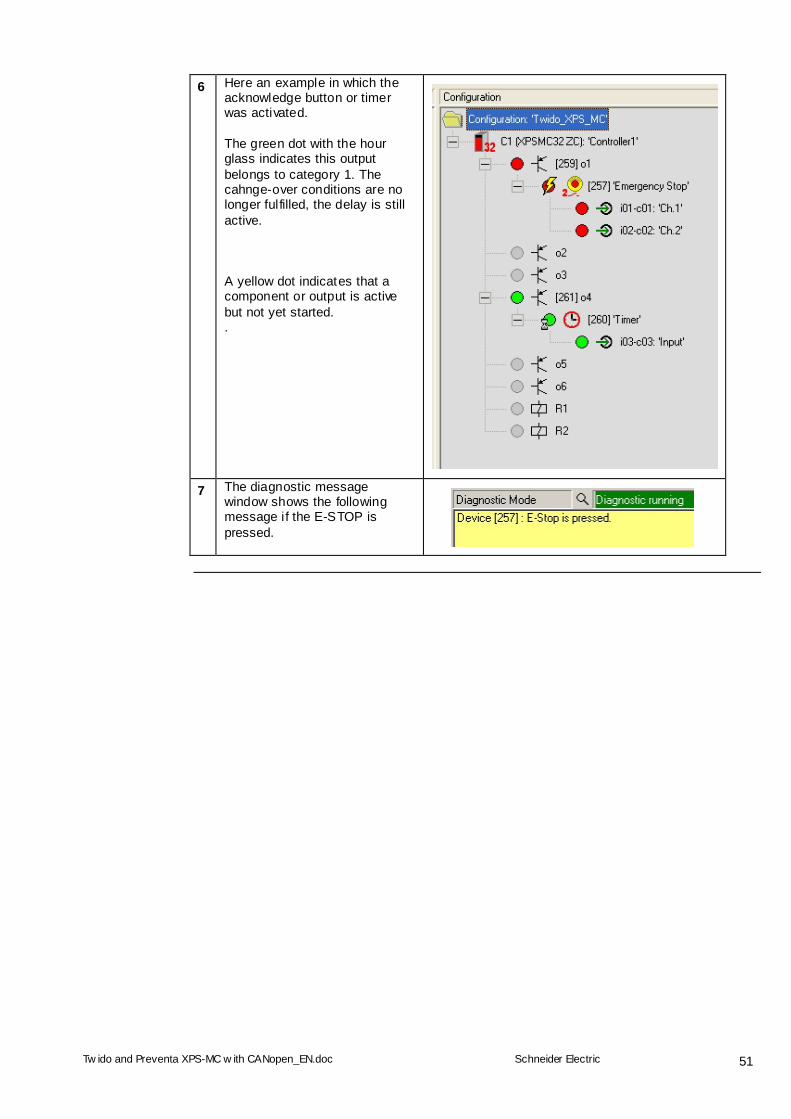
6 Here an example in which the acknowledge button or timer was activated. The green dot with the hour glass indicates this output belongs to category 1. The cahnge-over conditions are no longer fulfilled, the delay is still active. A yellow dot indicates that a component or output is active but not yet started. .
7 The diagnostic message window shows the following message if the E-STOP is pressed.
Tw ido and Preventa XPS-MC w ith CANopen_EN.doc
Schneider Electric
52
Access to Objects via SDO
General
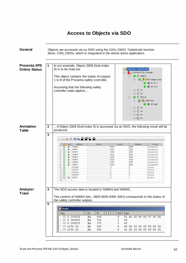
Objects are accessed via an SDO using the CAN_CMD1 TwidoSuite function block, CAN_CMD1, which is integrated in the above demo application.
Preventa XPS Online Status
1 In our example, Object 2008 (Sub-index 0) is to be read out. This object contains the states of outputs 1 to 8 of the Preventa safety controller. Assuming that the following safety controller state applies… .
Animation Table
2 …if Object 2008 (Sub-index 0) is accessed via an SDO, the following result will be produced:
3
Analyzer Trace
4 The SDO access data is located in %MW4 and %MW5. The content of %MW4 (bin.: 0000 0000 0000 1001) corresponds to the states of the safety controller outputs.
5
Tw ido and Preventa XPS-MC w ith CANopen_EN.doc
Schneider Electric
53
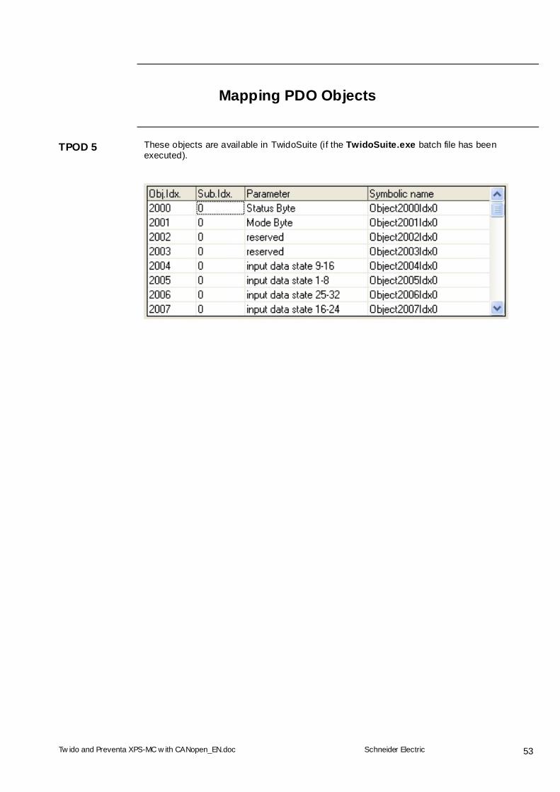
Mapping PDO Objects
TPOD 5
These objects are available in TwidoSuite (i f the TwidoSuite.exe batch file has been executed).
Tw ido and Preventa XPS-MC w ith CANopen_EN.doc
Schneider Electric
54
Appendix
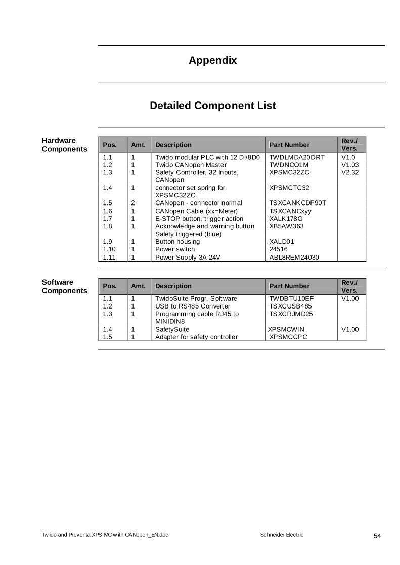
Detailed Component List
Pos. Amt. Description Part Number Rev./ Vers.
Hardware Components
1.1 1 Twido modular PLC with 12 DI/8D0 TWDLMDA20DRT V1.0 1.2 1 Twido CANopen Master TWDNCO1M V1.03 1.3 1 Safety Controller, 32 Inputs,
CANopen XPSMC32ZC V2.32
1.4 1 connector set spring for XPSMC32ZC
XPSMCTC32
1.5 2 CANopen - connector normal TSXCANKCDF90T 1.6 1 CANopen Cable (xx=Meter) TSXCANCxyy 1.7 1 E-STOP button, trigger action XALK178G 1.8 1 Acknowledge and warning button
Safety triggered (blue) XB5AW363
1.9 1 Button housing XALD01 1.10 1 Power switch 24516 1.11 1 Power Supply 3A 24V ABL8REM24030
Pos. Amt. Description Part Number Rev./ Vers.
Software Components
1.1 1 TwidoSuite Progr.-Software TWDBTU10EF V1.00 1.2 1 USB to RS485 Converter TSXCUSB485 1.3 1 Programming cable RJ45 to
MINIDIN8 TSXCRJMD25
1.4 1 SafetySuite XPSMCWIN V1.00 1.5 1 Adapter for safety controller XPSMCCPC
Tw ido and Preventa XPS-MC w ith CANopen_EN.doc
Schneider Electric
55
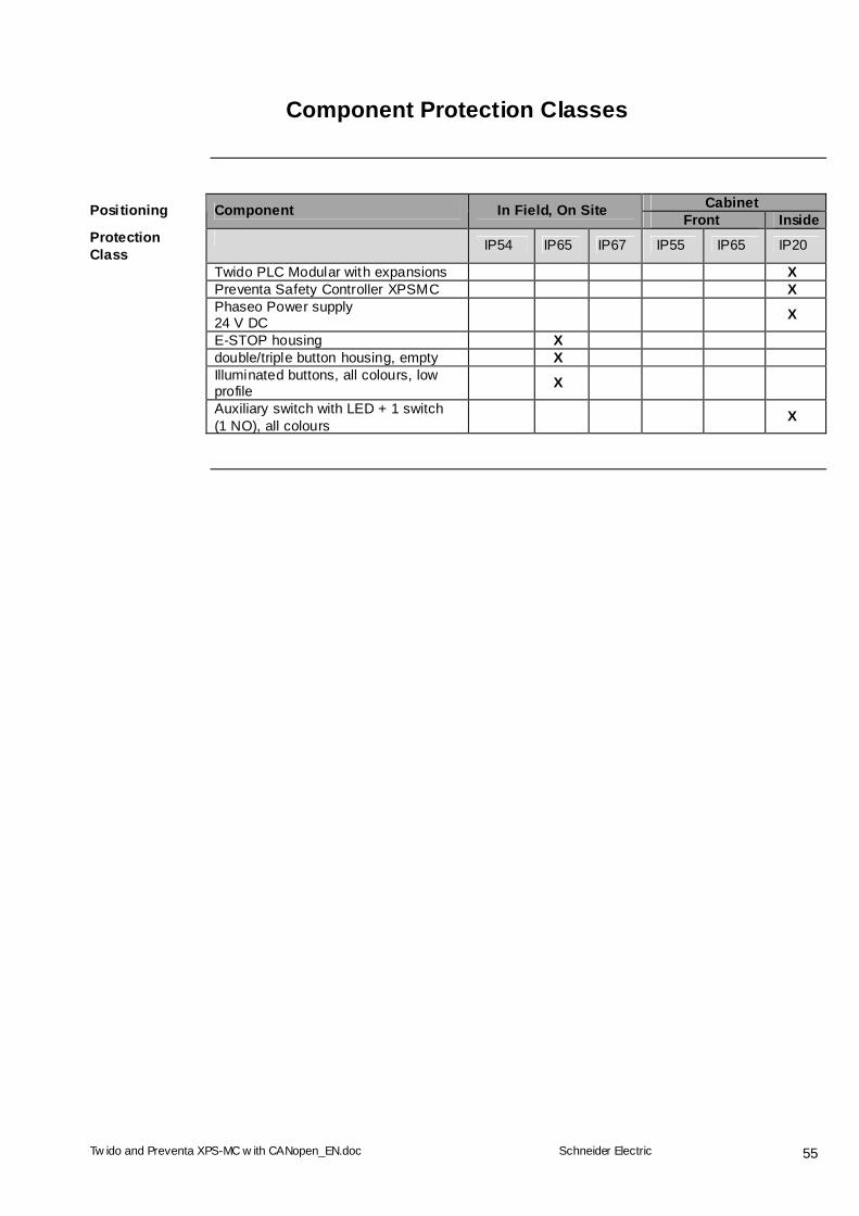
Component Protection Classes
Cabinet Positioning Component In Field, On Site Front Inside Protection Class
IP54 IP65 IP67 IP55 IP65 IP20
Twido PLC Modular with expansions X Preventa Safety Controller XPSMC X Phaseo Power supply
24 V DC X
E-STOP housing X double/triple button housing, empty X Illuminated buttons, all colours, low
profile X
Auxiliary switch with LED + 1 switch (1 NO), all colours
X
Tw ido and Preventa XPS-MC w ith CANopen_EN.doc
Schneider Electric
56
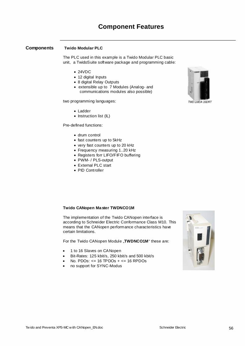
Component Features
Components Twido Modular PLC
The PLC used in this example is a Twido Modular PLC basic unit, a TwidoSuite software package and programming cable:
24VDC 12 digital Inputs 8 digital Relay Outputs extensible up to 7 Modules (Analog- and
communications modules also possible)
two programming languages:
Ladder Instruction list (IL)
Pre-defined functions:
drum control fast counters up to 5kHz very fast counters up to 20 kHz Frequency measuring 1..20 kHz Registers forr LIFO/FIFO buffering PWM- / PLS-output External PLC start PID Controller
Twido CANopen Master TWDNCO1M The implementation of the Twido CANopen interface is according to Schneider Electric Conformance Class M10. This means that the CANopen performance characteristics have certain limitations. For the Twido CANopen Module „TWDNCO1M“ these are: 1 to 16 Slaves on CANopen Bit-Rates: 125 kbit/s, 250 kbit/s and 500 kbit/s No. PDOs: <= 16 TPDOs + <= 16 RPDOs no support for SYNC-Modus
Tw ido and Preventa XPS-MC w ith CANopen_EN.doc
Schneider Electric
57
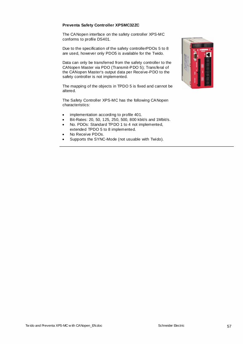
Preventa Safety Controller XPSMC32ZC The CANopen interface on the safety controller XPS-MC conforms to profile DS401. Due to the specification of the safety controllerPDOs 5 to 8 are used, however only PDO5 is available for the Twido. Data can only be transferred from the safety controller to the CANopen Master via PDO (Transmit-PDO 5); Transferal of the CANopen Master‘s output data per Receive-PDO to the safety controller is not implemented. The mapping of the objects in TPDO 5 is fixed and cannot be altered. The Safety Controller XPS-MC has the following CANopen characteristics: implementation according to profile 401. Bit-Rates: 20, 50, 125, 250, 500, 800 kbit/s and 1Mbit/s. No. PDOs: Standard TPDO 1 to 4 not implemented,
extended TPDO 5 to 8 implemented. No Receive PDOs. Supports the SYNC-Mode (not usuable with Twido).
Schneider Electric GmbH Steinheimer Strasse 117 D - 63500 Seligenstadt Germany Twido and Preventa XPS-MC with CANopen_EN.doc
As standards, specifications and designs change from time to time, please ask for confirmation of the information given in this publication. 58
Contact
Author Telephone E-Mail
Schneider Electric GmbH Machines & Process Architectures
+49 6182 81 2555 [email protected]