Embed Size (px)
Citation preview
Tutorials inComplexPhotonic
Media
preprint of
Editors:Mikhail A. Noginov
Graeme DewarMartin W. McCall
Nikolay A. Zheludev
© 2009, SPIE Press, Bellingham, Washington, USAPrint ISBN13: 9780819477736
eISBN: 9780819480934DOI: 10.1117/3.832717
http://spiedigitallibrary.aip.org/ebooks/spie/press_monographs/pm194

Chapter 19
Slow and Fast LightJoseph E. Vornehm, Jr. and Robert W. BoydInstitute of Optics, University of Rochester, NY, USA
19.1 Introduction 219.1.1 Phase velocity 319.1.2 Group velocity 319.1.3 Slow light, fast light, backward light, stopped light 6
19.2 Slow Light Based on Material Resonances 819.2.1 Susceptibility and the Kramers–Kronig relations 819.2.2 Resonance features in materials 919.2.3 Spatial compression 1019.2.4 Two-level and three-level models 1119.2.5 Electromagnetically induced transparency (EIT) 1219.2.6 Coherent population oscillation (CPO) 1219.2.7 Stimulated Brillouin and Raman scattering 1319.2.8 Other resonance-based phenomena 14
19.3 Slow Light Based on Material Structure 1519.3.1 Waveguide dispersion 1519.3.2 Coupled-resonator structures 1519.3.3 Band-edge dispersion 17
19.4 Additional Considerations 1719.4.1 Distortion mitigation 1719.4.2 Figures of merit 1719.4.3 Theoretical limits of slow and fast light 1819.4.4 Causality and the many velocities of light 19
19.5 Potential Applications 2219.5.1 Optical delay lines 2319.5.2 Enhancement of optical nonlinearities 2619.5.3 Slow- and fast-light interferometry 27
References 29

Slow and Fast Light
+
+
+...
Figure 19.1: A pulse as the sum of its Fourier components. Each of the Fourier components(sinusoids, or monochromatic waves) that constitute the pulse must have the proper rela-tive amplitude and phase in order to preserve the pulse shape. If the Fourier componentsbecome out of phase, the pulse will be distorted.
19.1 Introduction
In early 1999, a news article in the prestigious journal Nature led off with the an-nouncement, “An experiment with atoms at nanokelvin temperatures has producedthe remarkable observation of light pulses traveling at velocities of only 17 m/s.”The review continued with the understatement, “Observation of light pulses prop-agating at a speed no faster than a swiftly moving bicycle. . . comes as a surprise.”1
These findings (and their review) marked the beginning of the current wave of in-terest in the field that has come to be called “slow light.”2
When we refer to “the speed of light,” we typically mean c, the phase velocity oflight in a vacuum, or the speed of propagation of the phase fronts of monochromaticlight. The phase fronts travel more slowly through a material, propagating at thespeed c/n, where n is the index of refraction of the medium. However, this ordinaryslowing of the phase velocity is not slow light. “Slow light” and “fast light” referto changes in the group velocity of light in a medium.
A pulse of light can be decomposed mathematically into a group of monochro-matic waves at slightly different frequencies, as in Fig. 19.1. In a dispersive ma-terial, these monochromatic waves travel at different speeds. When one views thepropagation of the pulse as a whole, its apparent velocity depends on the extentof the spread of individual monochromatic-wave velocities. Each monochromaticwave travels at its own phase velocity, while the pulse travels at the group velocity.
Of course, the group velocity of a pulse of light is not a new concept. The fieldof slow and fast light has drawn on theoretical and developments from the workof Sommerfeld and Brillouin from 1907 to 1914,3, 4 experiments with early laseramplifiers in 1966,5 and other work done through the end of the 20th century.6, 7
(For more of the history behind slow and fast light, see Refs. 8 and 9.)

Tutorials in Complex Photonic Media
19.1.1 Phase velocity
Consider the (complex) electric field of a monochromatic electromagnetic planewave of amplitude E0:
E(z, t) = E0ei(kz−ωt). (19.1)
Here, ω is the angular frequency of the plane wave, k is the wavevector, z is theposition in space, and t is the time. When we speak of the propagation of the planewave, we mean the motion of the wave’s phase fronts, or surfaces of constant phase.If we define
φ = kz − ωt (19.2)
and rewrite the plane wave as
E(z, t) = E0eiφ, (19.3)
we see that the phase fronts are defined by constant values of φ. For convenience,we observe the motion of the phase front located at the origin z = 0 at time t = 0(such that φ = 0). This motion is then defined by
kz − ωt = 0. (19.4)
To account for dispersion, the wavevector k and the refractive index of the mediumn are written as functions of ω. We ignore absorption for the moment and write thewavevector as
k(ω) =n(ω)ω
c. (19.5)
By substituting Eq. (19.5) into Eq. (19.4), we find
z =ω
k(ω)t =
c
n(ω)t ≡ vpt. (19.6)
Thus, we have found the phase velocity vp, or the speed of propagation of the phasefront, to be
vp(ω) =ω
k(ω)=
c
n(ω). (19.7)
19.1.2 Group velocity
The propagation velocity of a pulse can be derived by requiring that the pulse shaperemain constant under propagation, meaning its plane-wave Fourier componentsmaintain their relative amplitudes and phases. Absorption needs to be included inthe derivation, so we first define the complex wavevector kc(ω) as
kc(ω) = k(ω) + iα(ω)
2=n(ω)ω
c+ i
α(ω)
2. (19.8)

Slow and Fast Light
Here, n(ω) is the (real) refractive index in the usual sense. The parameter α(ω) isthe linear intensity absorption per unit length experienced by a plane wave:
I(z) ∝ |E|2 =∣∣∣E0e
iω(nz/c−t)e−(α/2)z∣∣∣2 = |E0|2e−αz. (19.9)
Assuming that the Fourier components are in a sufficiently narrow bandwidth ∆ωaround some center frequency (or carrier frequency) ω0, we define ω = ω0 + ∆ωand expand the real and imaginary parts of kc(ω) in a Taylor series about ω0:
k(ω) = k0 + k1∆ω +1
2k2∆ω2 +
1
6k3∆ω3 + · · · =
∞∑m=0
kmm!
(∆ω)m, (19.10)
α(ω) = α0 + α1∆ω +1
2α2∆ω2 +
1
6α3∆ω3 + · · · =
∞∑n=0
αnn!
(∆ω)n, (19.11)
where we have defined
km ≡dmk
dωm
∣∣∣∣ω=ω0
, (19.12)
αn ≡dnα
dωn
∣∣∣∣ω=ω0
. (19.13)
Let us now consider a pulse, broken down into a sum of plane-wave Fouriercomponents as in Fig. 19.1. We write the Fourier components as
E(z, t) = E1ei[kc(ω1)z−ω1t] + E2e
i[kc(ω2)z−ω2t] + · · ·= E1e
i[k(ω1)z−ω1t]e−α(ω1)z/2 + E2ei[k(ω2)z−ω2t]e−α(ω2)z/2 + · · ·
=∑j
Eje−iωjt exp[ik(ωj)z] exp[−α(ωj)z/2]. (19.14)
For each Fourier component, we define ∆ωj = ωj − ω0. We then substituteEqs. (19.10) and (19.11) into Eq. (19.14). Next, we take the ω0, k0, and α0 termsoutside the sums, and we take the k1 term outside the sum over m, giving
E(z, t) =∑j
Eje−i(ω0+∆ωj)t exp
[iz∞∑m=0
kmm!
(∆ωj)m
]
× exp
[−z
2
∞∑n=0
αnn!
(∆ωj)n
]= e−α0z/2ei(k0z−ω0t)
∑j
Eje−i∆ωj(t−k1z)
× exp
[iz∞∑m=2
kmm!
(∆ωj)m
]exp
[−z
2
∞∑n=1
αnn!
(∆ωj)n
]. (19.15)

Tutorials in Complex Photonic Media
In order for the pulse to propagate unchanged through a medium, the relativeamplitudes and phases of the plane-wave Fourier components must remain con-stant. Propagation can at most be allowed to scale the entire pulse by a singlecomplex constant. More specifically, if the pulse propagates with unchanged shapefrom the origin to the point z in a time t, we can write the propagation requirementformally as
E(z, t) = reiφE(0, 0). (19.16)
Here, r and φ are free variables describing the change in amplitude and phaseduring propagation. By expanding the right-hand side of Eq. (19.16) according tothe definition in Eq. (19.14), we find
reiφE(0, 0) = reiφ∑j
Eje−iωj0 exp[ik(ωj) · 0] exp[−α(ω) · 0/2]
= reiφ∑j
Ej . (19.17)
In order for the pulse shape to remain unchanged upon propagation, Eq. (19.16)must be satisfied, meaning Eqs. (19.15) and (19.17) must be equal. In general,Eq. (19.16) can be satisfied only when a number of conditions hold true:
r = e−α0z/2, (19.18)
eiφ = ei[k0z−ω0t], (19.19)
t = k1z, (19.20)
k2 = k3 = · · · = 0, and (19.21)
α1 = α2 = α3 = · · · = 0. (19.22)
Equations (19.18) and (19.19) are automatically satisfied because r and φ are freevariables that define the amplitude and phase change acquired by the pulse duringpropagation. It is shown below that Eq. (19.20) defines the group delay and groupvelocity, while Eqs. (19.21) and (19.22) have important consequences for pulsepropagation and distortion.
The group delay τg, or the time required for the pulse to propagate a distancez, is given by Eq. (19.20) as
τg ≡ t = k1z = zdk
dω. (19.23)
The derivative is evaluated at ω = ω0; we have dropped that notation for conve-nience. The group velocity vg, or the speed at which the pulse envelope propagates,can then be defined as
vg ≡z
τg=
(dk
dω
)−1
=
[d
dω
(nωc
)]−1
= c
(n+ ω
dn
dω
)−1
=c
ng, (19.24)

Slow and Fast Light
where the quantity
ng ≡ n(ω) + ωdn
dω(19.25)
is called the group index, in analogy to Eq. (19.7). The first term in Eq. (19.25) isthe refractive index, which may sometimes be termed the phase index (for contrastwith the group index). The second term is a measure of the dispersion. In the liter-ature, a positive value of dn/dω is referred to as normal dispersion, and a negativevalue is called anomalous dispersion. Note that under normal circumstances, thesecond term in Eq. (19.25) is very small, so ng ≈ n and vg ≈ vp. The promise ofslow and fast light lies in the fact that, because ω is so large in the optical regime,any method that increases the magnitude of the dispersion even slightly can produceastonishingly large or small group velocities.
Equations (19.21) and (19.22) have important consequences for slow light.In order for a general pulse shape to propagate wholly unchanged, second-orderdispersion (group velocity dispersion, or GVD) and higher-order dispersion termsmust be zero, and absorption must be spectrally flat. Any higher-order dispersionor absorption terms will introduce some amount of distortion into the pulse. As weshall see in Sec. 19.2.1, the Kramers–Kronig relations dictate that Eqs. (19.21) and(19.22) can never precisely be satisfied in real-world media. A great deal of exper-imental research in slow light is aimed at reducing the effects of pulse distortion.
The statement in Sec. 19.1 that the pulse travels at the group velocity does notgive a complete picture. The pulse velocity is equal to the group velocity whendistortion is minimal and the pulse more or less maintains its shape. However,severe distortion can cause the pulse to “break up” into a shape that has severalpeaks. In such situations, the group velocity is still defined according to Eq. (19.24),but there is no longer a single pulse for which to define a meaningful pulse velocity.
19.1.3 Slow light, fast light, backward light, stopped light
Slow light, then, is light that travels at an exceptionally slow group velocity, orin a medium with an exceptionally large group index.2 Traditionally, slow light isdefined as having vg vp, which occurs when ng np. Slow-light techniquesaim to increase ng by increasing dispersion (dn/dω). However, dispersion neednot be positive. It can be zero, negative, or (nearly) infinite, leading to several otherregimes of operation.
Fast light is light for which vg > c. Fast light occurs in media for which0 ≤ ng < 1. Such propagation is also called “superluminal,” owing to the factthat the group velocity is greater than the speed of light in vacuum. The limit offast light is zero group index, or infinite effective group velocity, in the so-calledcritically anomalous dispersion regime;10 in such a regime, the pulse appears toleave the medium at exactly the same time as it enters. It should be noted that fast-light propagation is entirely within the bounds of causality and special relativity.11
No information can be communicated superluminally; for more discussion on this

Tutorials in Complex Photonic Media
region of negativegroup index
Figure 19.2: Backward pulse propagation in a medium with ng < 0. Each plot shows asnapshot in time, with time advancing downward.
point, see Sec. 19.4.4. Fast light may also be defined as occurring when vg > vpand 0 ≤ ng < n.
Backward light occurs in media for which ng < 0. A pulse travels in such amedium with vg < 0, giving an apparent backward propagation of the pulse withinthe medium.7, 12, 13 In this regime, shown in Fig. 19.2, the pulse appears to leave themedium before it enters, and the peak of the pulse within the medium propagatesbackwards from the time the outbound pulse leaves to the time the inbound pulseenters. Energy still flows in the forward direction.14 Causality is not violated here,either; the effect can be seen as a form of pulse reshaping, selectively amplifyingthe long leading edge of a Gaussian pulse and attenuating the original peak.
Stopped light (or stored light) is related to slow light. Stopped-light techniquesare used to “stop” or “trap” a pulse of light inside a medium for some amount oftime. The pulse is slowed as it enters the medium, and then the medium is alteredor stimulated so that the pulse is stored for a short time and then retrieved. Theactual storage may happen by inducing the group velocity to become zero (and thegroup index to become infinite) or by some other means, such as by mapping thepulse into the spin coherence of a coherently prepared atomic medium.15, 16
These different regimes of operation are all concerned with inducing strongdispersion and thus use very similar techniques. They are often all grouped togetherunder the heading of “slow light” or “slow and fast light.”

Slow and Fast Light
19.2 Slow Light Based on Material Resonances
19.2.1 Susceptibility and the Kramers–Kronig relations
Both the refractive index n(ω) and the absorption coefficient α(ω) of a mediumhave their origin in the susceptibility of the medium χ(ω). When an electric fieldis applied to a medium, the charged particles in the medium (the electrons andprotons) shift their positions in response to the field. This shift in the positionsof the charges creates an additional electric field. The electric dipole moment perunit volume of the material is known as the polarization density P , or simply thepolarization. Some materials are more susceptible than others to being polarizedby an incident electric field. The degree to which the material may be polarized bya given electric field is known as the electric susceptibility χ and is defined by
P = ε0χE, (19.26)
where E is the strength of the electric field and ε0 is the permittivity of free space.The permittivity ε of the medium is defined as
ε = ε0εr = ε0(1 + χ), (19.27)
and the refractive index and absorption coefficient are defined respectively as
n(ω) = Re √εr = Re
√1 + χ(ω)
, (19.28a)
α(ω) =2ω
cIm √εr =
2ω
cIm√
1 + χ(ω). (19.28b)
When χ(ω) is small, such as for dilute gases, Eqs. (19.28) simplify to
n(ω) ≈ 1 +1
2Re χ(ω) , (19.29a)
α(ω) ≈ ω
cIm χ(ω) . (19.29b)
One can thus think of the real part of the susceptibility as corresponding to therefractive index n(ω) and the imaginary part as corresponding to the absorptioncoefficient α(ω). The correspondence is a useful conceptual device, although onemust remember that Eqs. (19.29) are not strictly true for media with a strong elec-tromagnetic response (a large susceptibility). In such cases, the more general formsin Eqs. (19.28) should be used.
The medium’s electromagnetic response must be causal (it must obey causal-ity). Any change in P at time t must be caused by changes in E that happen beforetime t. In other words, the cause must precede the effect. This may seem obvious,but the causality requirement has important consequences: It can be shown that

Tutorials in Complex Photonic Media
the electromagnetic susceptibility of any causal medium also obeys the Kramers–Kronig relations
Im χ(ω) =−2ω
π
∫ ∞0
Re χ(ω′)ω′2 − ω2
dω′, (19.30a)
Re χ(ω) =2
π
∫ ∞0
ω′ Im χ(ω′)ω′2 − ω2
dω′. (19.30b)
These relations lead to several important results. First, any material that exhibitsabsorption must also possess dispersion. Conversely, any dispersive medium mustalso possess some spectral variation in absorption, meaning that dα/dω (and α1)cannot be zero for all ω. Thus, distortion is ever-present in slow-light media. Ad-ditionally, the Kramers–Kronig relations dictate that n(ω) will be nearly linear inthe neighborhood of a smooth peak or valley in the absorption spectrum. The valueof dn/dω (and k1) can be either positive or negative, according to the concavity ofthe peak. As explained in the next section, one important slow-light technique isto induce sharp changes in the absorption spectrum. (For further discussion of theKramers–Kronig relations, see Sec 1.7 in Ref. 17.)
19.2.2 Resonance features in materials
Many of the spectral features of a material’s optical response come from materialresonances. In many instances, the motion of bound charged particles in a material(such as electrons bound to atoms or molecules, or nuclei within a crystal lattice)is constrained to the form of a damped harmonic oscillator, similar to a mass ona spring. In this model, often called the Lorentz model, the charged particle tendsto oscillate at a resonance frequency ωr. The equation of motion of the chargedparticle can then be written as
d2x
dt2+ 2γr
dx
dt+ ω2
rx =eE
m, (19.31)
where x is the particle’s displacement from its equilibrium position, e is the chargecarried by the particle (e < 0 for an electron), E is the magnitude of the appliedelectric field, m is the charged particle’s mass, and γr is a damping coefficient. Itcan be shown that, under these conditions, the susceptibility χ of the medium dueto the resonance has the form
χ(ω) ∝ 1
ω2r − ω2 − 2iωγr
, (19.32)
which gives the absorption spectrum α(ω) a Lorentzian line shape centered at ωrwith linewidth γr. The Kramers–Kronig relations dictate that n(ω) and α(ω) musthave the relationship shown in Fig. 19.3(a). (For further discussion of materialresonances, see Secs. 1.4 and 3.5 of Ref. 17 or Sec. 5.5 of Ref. 18.)

Slow and Fast Light
ωr ωr + γr
n− 1α
ω
(a)
ωr ωr + γr
ng − 1
ω
(b)Figure 19.3: Dispersive features of an absorption resonance. (a) The absorption α anddispersion n − 1 of an absorption resonance at frequency ωr with linewidth γr. Near thepoint ω = ωr (but not precisely at that point), α reaches a peak and n − 1 crosses theaxis. (b) Group index of the same absorption resonance, using the same ω axis. Note thatfast-light behavior (|ng| > c) is exhibited near ω = ωr, while slow-light behavior is exhibitedaround ω = ωr ± γr.
Of course, material systems have many different resonances, each with its owncenter frequency, linewidth, and relative strength. Beyond natural material reso-nances, resonances of a similar Lorentzian form can also be induced by certainoptical processes. Lasing, for example, consists of creating an inverted population,such that a certain atomic or molecular transition (a resonance) experiences gain.In that case, ωr is the frequency of the lasing transition, γr is its linewidth, and thevalue of α(ωr) is negative, indicating gain rather than absorption. The Kramers–Kronig relations then dictate essentially a reversed shape for n(ω).
It is easy to see from Fig. 19.3 how slow and fast light can be achieved in suchsystems. Near ω = ωr, n(ω) varies nearly linearly with ω, making d2n/dω2 nearlyzero. The absorption feature is only slightly dependent on ω near the resonance.However, |dα/dω| becomes very large as the absorption drops off away from ωr.One must be careful that the pulse spectrum does not extend too far into the regionof large |dα/dω|. Notice also that fast light occurs in regions of strong absorption;the fast-light experimenter may choose to deal with this absorption, to mitigateit somehow, or to create fast-light features using any of several other means thatavoids absorption.
19.2.3 Spatial compression
It is clear that the reduced group velocity in slow light leads to spatial compressionof the pulse by a factor equal to the group index. If a pulse of duration τ deceleratesfrom speed c to speed c/ng, its length L must likewise decrease from L ∝ cτ toL′ = L/ng. Conservation of energy then dictates that if the pulse energy was

Tutorials in Complex Photonic Media
|1〉
|2〉
ω
(a)
|1〉
|2〉
|3〉
ωp
ωc
(b)Figure 19.4: Energy-level models of an atom (or other quantum-mechanical system). Themodel can be reduced to include only those energy levels involved in resonant absorptionor emission transitions (or nearly resonant transitions). All other levels can be neglected.(a) Two-level model. Incoming light at frequency ω is nearly resonant with the transitionbetween energy levels |1〉 and |2〉. (b) Three-level model. Incoming light at frequency ωp isnearly resonant with the transition between energy levels |1〉 and |2〉, and light at frequencyωc is nearly resonant with the transition between energy levels |3〉 and |2〉. Typically, ωc is astrong coupling beam or pump beam, while ωp is a weaker probe beam.
distributed over length L but is compressed down to length L′, the energy densityu must increase by the same factor to u′ = ngu.
Interestingly, the intensity of a pulse I = uvg is unchanged upon entering aslow-light medium, because the increase in u is canceled exactly by the decreasein vg. Likewise, the electric field strength E ∝
√I is unaffected by changes in the
group velocity. Thus, although the pulse energy is spatially compressed, its peakelectric field strength is unchanged.8, 19 In contrast to this result, slow light achievedin coupled resonators or photonic crystals is accompanied by an increase in electricfield strength.20
19.2.4 Two-level and three-level models
Optical interactions with atoms (or molecules or other systems) can be describedquantum-mechanically using a two- or three-level model. In the two-level modelshown in Fig. 19.4(a), the incident light at some frequency ω is assumed to beresonant (or nearly resonant) with the atomic transition between energy levels |1〉and |2〉. (By resonant, we mean that the photon energy E = hω is the same asthe energy difference between states |1〉 and |2〉, and the optical transition is notforbidden by other issues such as parity.) Formally, the incident light has someprobability of causing an atomic transition between any two energy levels; however,if the light is nearly resonant with the |1〉–|2〉 transition, the probabilities of othertransitions become vanishingly small, and all other energy levels can be neglected.Thus, the atomic model is effectively reduced to two levels. Similarly, the three-level model shown in Fig. 19.4(b) is applicable when light fields are applied attwo different frequencies ωp and ωc, which are respectively resonant (or nearlyresonant) with the |1〉–|3〉 and |2〉–|3〉 transitions. (Note that the |1〉–|2〉 transitionis typically forbidden by dipole selection rules.) The three-level model is often

Slow and Fast Light
useful in experiments where the ωc field is a strong coupling field or pump fieldthat induces some optical effect and the ωp field is a weak probe field that measuresor “sees” the effect.
19.2.5 Electromagnetically induced transparency (EIT)
Electromagnetically induced transparency (EIT) allows a very narrow window ofincreased transparency (a spectral hole) to be introduced in an absorption reso-nance.21 The narrowness and depth of the spectral hole lead to a large group in-dex, producing slow light. A three-level Λ-type model of an atom is shown inFig. 19.4(b). The atom starts in state |1〉, the ground state. A strong pump field(also called a coupling field) at frequency ωc is applied to the |2〉–|3〉 transition insuch a way that a coherence is introduced between the |1〉–|3〉 and |2〉–|3〉 transi-tions. If a weak probe at frequency ωp is later applied to the |1〉–|3〉 transition, itwill undergo little or no absorption, whereas it would ordinarily be absorbed read-ily. The hole created in the probe absorption spectrum at ωp is very narrow, so bythe Kramers–Kronig relations, the medium has a large dn/dω and a large groupindex at the same frequency.
As EIT is a quantum interference phenomenon, it is crucial that the EIT mediumbe maintained in an environment that preserves quantum coherence.21 Typically,the medium is kept at cryogenic temperatures or, for vapors, at low pressure. Anumber of other requirements must also be met, and achieving EIT can be quitedifficult experimentally. Despite these restrictions, EIT has been a popular experi-mental method for achieving slow light. The experiment that sparked recent interestin slow light was carried out using EIT in a Bose-Einstein condensate (BEC).2 EIT-based slow-light experiments have been carried out in hot alkali vapor,16 cold alkalivapor,22 crystals,15 semiconductor quantum wells,23–25 and vapor confined withinphotonic band-gap fiber26 and have been proposed in doped optical fiber27 andsemiconductor quantum dots.28 Certain transparency effects similar to EIT havebeen predicted in resonator systems29–32 and plasmas.33–35
EIT is also associated with an enhancement of the medium’s optical nonlin-earity.19 When the fields applied to a resonant medium are tuned to a resonance,the optical nonlinearity of the medium reaches a local maximum. In the absenceof EIT, linear absorption also reaches a local maximum, making the nonlinearityunusable. EIT allows access to these resonant nonlinearities that would otherwisebe precluded by absorption. It would be incorrect to say that the nonlinearity en-hancement in EIT is caused by the slow-light effect; however, the slow-light effectand the nonlinearity enhancement in EIT are inseparable.
19.2.6 Coherent population oscillation (CPO)
Coherent population oscillation (CPO) occurs in a two-level atom when a pumpbeam at frequency ω and a probe beam at frequency ω + δ are applied to the sametransition, such as the |1〉–|2〉 transition in Fig. 19.4(a). If ω and ω + δ both lie

Tutorials in Complex Photonic Media
within the natural linewidth 1/T1 of the transition, a portion of the atomic popula-tion oscillates between levels |1〉 and |2〉 at the beat frequency δ. The oscillatingpopulation produces a narrow hole in the absorption line centered at frequency ω.By the Kramers–Kronig relations, the narrow spectral hole results in a rapid indexvariation, producing slow light. (Of course, if the atomic population is initially inthe excited state, the CPO effect produces a hole in the gain spectrum, giving afast-light effect.)36, 37
Equivalently, CPO can be viewed as a time-dependent saturable absorption orsaturable gain effect. As part of the population moves from level |1〉 to level |2〉, thatpart of the population is unavailable to participate in the absorption process, lead-ing to reduced absorption. A slow-light effect is achieved through pulse reshaping:The leading edge of the pulse is selectively attenuated, producing an effective delayof the peak. As part of the population moves from level |2〉 to level |1〉, the corre-sponding gain saturation occurs, giving a fast-light effect by selectively amplifyingthe leading edge of the peak. Note that the optimal pulse bandwidth is of the orderof δ, so approximately one complete population cycle occurs.38–41
CPO as a slow- and fast-light method has several advantages over EIT. CPO ismuch easier to achieve at room temperature. Both methods can have similarly nar-row linewidths, resulting in sharp dispersion and extreme group velocities. Addi-tionally, CPO slow- and fast-light effects may be achieved with only a single beamby inducing a sinusoidal amplitude modulation at frequency δ on a pump beam atω, or even a single pulse with approximate bandwidth δ. However, CPO typicallysuffers from a higher degree of residual absorption than EIT. Also, the bandwidthof CPO is limited to the natural linewidth 1/T1 of the atomic transition. CPO hasbeen achieved in a variety of experimental setups, including in crystals,37, 42 er-bium ions as dopants in an optical fiber,14 semiconductor waveguides,43 quantumdots in semiconductor waveguides,44 and quantum dot semiconductor optical am-plifiers (QD-SOAs).45 CPO has also been used to generate slow light at cryogenictemperatures (10 K) in a semiconductor quantum well structure.46
19.2.7 Stimulated Brillouin and Raman scattering
Both stimulated Brillouin scattering (SBS) and stimulated Raman scattering (SRS)involve the scattering of light off a vibrational wave. If a pump field at frequency ωscatters off a vibrational wave at frequency Ω, scattered fields are generated at theStokes frequency ωS = ω −Ω. The frequency Ω can be up to several gigahertz forSBS and up to several terahertz for SRS. If a probe field is applied to the mediumat the Stokes frequency, it will experience gain as energy is scattered from thepump into the Stokes frequency. By the Kramers–Kronig relations, the SBS orSRS gain line induces a slow-light dispersion curve in the vicinity of the probe(Stokes) frequency.
Stimulated Brillouin scattering is based on the electrostrictive effect, wherebymaterials experience a slight change in density (and hence refractive index) in re-

Slow and Fast Light
Ω
ωa
ω
ωS
ω
Figure 19.5: A typical level scheme for stimulated Raman scattering (SRS). The pumplaser at frequency ω couples molecules (or atoms) from the vibrational ground state to thevibrationally excited state, emitting Stokes photons at frequency ωS = ω−Ω and producinggain at the Stokes frequency (inner pair of slanted arrows). In the presence of the pump (andin the absence of four-wave mixing effects), anti-Stokes photons at frequency ωa = ω + Ωcan be absorbed by a stimulated Raman transition in ground-state molecules, resulting inloss at the anti-Stokes frequency (outer pair of slanted arrows). Note that the two upperlevels are so-called virtual levels and need not correspond to real energy levels.
sponse to an applied optical field. In SBS, the pump and probe fields beat togetherand induce a traveling density modulation (a pressure wave or acoustic wave) in themedium at frequency Ω. Energy from the pump wave then scatters off the acousticwave and into the probe field (since ωS = ω − Ω), which further enhances theacoustic wave, and so forth, creating a positive feedback loop. Absorption (or loss)increases at the anti-Stokes frequency ωa = ω + Ω. (If no Stokes field is appliedinitially, one can be generated by the scattering of the pump field off a thermalphonon at Ω. For further discussion of SBS, see Chaps. 8 and 9 of Ref. 17.) SBScan readily be induced in optical fibers.47, 48 Since SBS can be controlled via thepump, it can be tailored to minimize distortion49 and to optimize gain bandwidth.50
Stimulated Raman scattering works by inducing molecular transitions betweenvibrational sublevels. As shown in Fig. 19.5, molecular vibrations at frequency Ωare excited by the beating of the pump and probe fields; these molecular vibrationsscatter some energy from the pump into the Stokes sideband ωS = ω − Ω, and theprobe field experiences gain. In a normal thermal distribution at room temperature,there are far more molecules in the ground state than in the excited state; theseground-state molecules can now absorb light in the anti-Stokes sideband ωa = ω+Ω, due to the presence of the pump to complete the stimulated Raman transition tothe excited state. Thus, the anti-Stokes field, if present, experiences loss. (However,there is also a four-wave mixing component to SRS that can alter this balance. Forfurther discussion of SRS, see Chap. 10 of Ref. 17.) SRS can be observed not just inmolecules but also in atoms and crystals, i.e., in any system that can be vibrationallyexcited. Slow light based on SRS gain has been observed in both solids51, 52 andoptical fibers.53
19.2.8 Other resonance-based phenomena
A number of other slow-light techniques based on resonance phenomena have beenimplemented successfully. Picosecond pulses were delayed by as many as 80 pulse

Tutorials in Complex Photonic Media
widths by operating at the center frequency between two absorption lines (hy-perfine ground states) of cesium.54 Slow light was achieved using the gain of avertical-cavity surface-emitting laser (VCSEL) configured as a semiconductor op-tical amplifier (SOA) rather than as a laser.55 Slow light in semiconductors has alsobeen achieved using a number of different mechanisms, including several excitonicmechanisms.56–58 For more details on semiconductor effects, see Refs. 59 and 60and their references.
19.3 Slow Light Based on Material Structure
19.3.1 Waveguide dispersion
In an optical fiber, a fraction of the energy in a guided electromagnetic mode prop-agates in the core, and the remainder propagates in the cladding. The effective re-fractive index of the mode depends on this fraction. For different wavelengths, thefraction changes, producing an index variation with frequency. This dispersion isknown as waveguide dispersion or intramodal dispersion. Additionally, each modeof a multi-mode waveguide has its own group velocity; if a pulse coupled into amulti-mode waveguide propagates in several modes with different group velocities,intermodal dispersion results. For further discussion on dispersion in waveguides,see Chaps. 8 and 9 of Ref. 18 or Sec. 1.5 of Ref. 61.
Typical optical fibers do not have enough dispersion to be interesting for slow-light purposes. However, novel waveguides such as coupled-resonator structurescan provide greatly enhanced waveguide dispersion (see Sec. 19.3.2). Semicon-ductor quantum well and quantum dot structures have also been used for slow-lightexperiments.43, 57
19.3.2 Coupled-resonator structures
Slow-light effects have also been explored in coupled-resonator structures, alter-nately called coupled-resonator optical waveguides (CROWs) or coupled-cavitywaveguides (CCWs). Examples of such structures are shown in Fig. 19.6. Lowgroup velocities are observed in the propagation of light across the CROW, as aresult of weak coupling and feedback between the resonators.62 Here is a con-ceptual model of how the device works: Light couples evanescently into the firstresonator. As the light resonates there, it couples evanescently into the second res-onator, where it also resonates. It then couples evanescently into the third resonator,and so forth, until it has “leaked” across the entire waveguide.63
Photonic crystals (PCs or PhCs) are formed by introducing periodic refractiveindex changes in a dielectric medium. Because of the periodic index modulation,light within certain wavelength bands is unable to propagate in the photonic crys-tal. In analogy to semiconductor crystals, these bands are called forbidden bandsor photonic band gaps. Often, photonic crystals are made by drilling rectangularlyspaced air holes into a dielectric, with the index contrast between air and the dielec-tric providing the periodic index modulation. One-, two-, and three-dimensional

Slow and Fast Light
Figure 19.6: Several examples of coupled-resonator optical waveguides (CROWs). All de-vices can be fabricated as silicon waveguides. From top: Coupled Fabry–Pérot resonators,coupled one-dimensional photonic crystal defect resonators, coupled two-dimensional pho-tonic crystal defect resonators, coupled ring resonators. (Adapted from Ref. 63; used bypermission.)
photonic crystals can be formed in such a way. By convention, however, the term“photonic crystal” is typically reserved for two- and three-dimensional structureswith high index contrast. Two-dimensional photonic crystals are perhaps morecommon since three-dimensional photonic crystals are quite difficult to fabricate.
A small defect introduced in the photonic crystal lattice will allow light topropagate in the vicinity of the defect, creating a resonator (see Fig. 19.6). If aperiodic series of defects is introduced in the photonic crystal, the resonators cancouple evanescently, forming a photonic crystal defect waveguide, another formof CROW.63 Photonic crystals are particularly versatile, since they may be used todesign many different optical devices and may be fabricated out of virtually any di-electric media. Photonic crystal devices may be created in highly nonlinear opticalmedia as well. For example, the air holes in a photonic crystal lattice may be filledwith a fluid having a high nonlinearity.20
In CROW devices, the electric field is enhanced within the resonators, leadingto an enhancement of the optical nonlinearity.20, 63, 64 Nonlinear effects typicallydepend on the strength of the incident electric field raised to some power. In aresonator, the resonating electric field builds up, leading to an enhancement of thenonlinear effect. Coupled-resonator optical waveguides typically see a nonlinearityenhancement that scales as the square of the slowing factor.64
Tutorials in Complex Photonic Media
Slow light has also been explored in certain optical filters, including fiber Bragggratings65 and Moiré fiber gratings.66 These can be thought of conceptually (but notrigorously) as a series of coupled resonators. The dispersion and slow-light effectsin optical filters are similar to those of coupled-resonator structures.
19.3.3 Band-edge dispersion
Photonic band gap materials can be used to achieve slow light using another effect,one which they have in common with semiconductors. In the band gap, electro-magnetic waves cannot propagate. Steep dispersion exists near the band edges, andprecisely at the band edge, the group velocity goes to zero. At frequencies justoutside the band gap (i.e., just inside the transmission band), light propagates atextremely slow group velocities.67–71
19.4 Additional Considerations
19.4.1 Distortion mitigation
The Kramers–Kronig relations dictate that any slow-light system will cause somedegree of pulse distortion, as discussed in Sec. 19.2.1. In its simplest form, distor-tion takes the form of pulse broadening or compression, while more complicatedforms of distortion can lead to pulse break-up. Workers in the field of slow lighthave developed a number of techniques for minimizing pulse distortion. For in-stance, Wang and coworkers72 utilized the following scheme: Consider two res-onances of the type shown in Fig. 19.3(a), spaced far apart. The refractive indexwill follow a smooth line between the resonances, producing a nearly linear refrac-tive index profile (and hence a nearly constant group index) in the region directlybetween the two resonances. Such a configuration has since been used success-fully by others.54, 73, 74 One group suggested inducing two nearly overlapping reso-nances, which sum to produce a spectral region of nearly flat absorption and hencenearly flat group velocity.49 Another group proposed doing the same with threeresonances.75 In coherent population oscillation, adding a continuous-wave back-ground to the pulse can balance the competing effects of gain recovery and pulsespectrum broadening.76 Many further techniques have been suggested.
19.4.2 Figures of merit
Several figures of merit are in common use among workers in slow light. The groupindex ng may be quoted, either by itself or as the slowing factor S = c/vg.77 Themost common figure of merit is simply the group delay τg, the time delay inducedby propagation through the slow-light medium. This is nearly always the experi-mental quantity that is measured directly, so it is simple to report. However, it isgenerally easier to produce longer delays for longer pulses. Thus, a more mean-ingful measure is often the fractional delay, or the delay normalized by the pulsewidth.78 Fractional delay coincides more closely with the particular application of

Slow and Fast Light
slow-light delay lines and slow-light buffers for optical networking; fractional de-lay, then, becomes a measure of the number of bits that can be stored by such a de-lay line. Fast-light systems may be evaluated in terms of fractional advancement, ornegative fractional delay. To offer a truer estimate of the technological value of ex-perimental results, fractional delay is often quoted along with pulse width. Perhapsthe most useful single figure of merit for optical delay lines is the delay–bandwidthproduct (DBP), which is also equal to the maximum possible fractional delay in agiven slow-light system.79 The delay–bandwidth product must also be quoted withthe bit rate to be a definitive performance measure.
Many more figures of merit have been defined; indeed, the usefulness of a figureof merit depends on the merits it measures, which in turn depend on the intendedapplication. The maximum possible delay can be represented in other ways, suchas the length of a waveguide required to achieve a given time delay71 or the ratioof a quantum memory’s maximum storage time to the input pulse length.80 Otherfigures of merit often include some measure of the absorption experienced by thepulse, such as the ratio of the group index or the delay–bandwidth product to theabsorption coefficient,81, 82 or the time a signal can propagate in a slow-light bufferbefore needing regeneration or amplification.58 Pulse distortion can be measuredin several different ways, including the input–output pulse width ratio,76 degree ofdispersion near an absorption feature or a band edge,71 or group velocity dispersion(GVD). The effects of pulse distortion on a telecommunications system are oftenthe ultimate concern, so some experimenters use commercial telecommunicationstest equipment to test the bit-error rate (BER)83 or the eye opening.84
19.4.3 Theoretical limits of slow and fast light
The most general theoretical limits of the performance of slow-light systems werealready mentioned in Sec. 19.1.2: Group velocity dispersion (k2), frequency-de-pendent absorption (α1), and higher-order dispersion and absorption terms mustbe sufficiently small that the pulse is not distorted too much (though the degreeof acceptable distortion is often application dependent). Generally, total linear ab-sorption (αL) must also be sufficiently small that the signal can be detected. Morespecific limits than these depend on the particular slow-light technique in question.Some results are quoted here without further comment.
For many slow-light techniques, group velocity and bandwidth are propor-tional, requiring a trade-off between the two parameters.82, 85 Under many circum-stances, the minimum spatial extent occupied by a single optical bit in a slow-lightmedium is roughly one vacuum wavelength.82 Slow light using electromagneticallyinduced transparency (EIT) or coherent population oscillation (CPO) is most of-ten limited by residual absorption on line center (α0) and by frequency-dependentabsorption (α1 and higher terms).78, 86 The excited state lifetime limits fractionaldelay in CPO in the short-pulse limit.87 Group delay in EIT is partly limited byatomic collisions88 and by nonlinear effects.89 In slow-light systems using stimu-

Tutorials in Complex Photonic Media
−t0 t0
t
Figure 19.7: A truncated Gaussian pulse. The function has the value exp(−t2/2) in therange −t0 ≤ t ≤ t0 and is zero outside this range, so it has compact support. A trueGaussian pulse would have infinite extent and therefore infinite support.
lated Brillouin scattering (SBS) in optical fibers, there is a trade-off between in-creased bandwidth and reduced pulse distortion.84
19.4.4 Causality and the many velocities of light
Fast light (vg > c) and backward light (vg < 0) seem at first to violate causality.However, careful analysis shows that this is not so. Causality is the requirement thatany effect must be preceded by its cause. When combined with the special theory ofrelativity, causality requires that no information travel faster than the speed of light.(Otherwise, it would be possible to violate causality in certain frames of reference.)What does this mean for a group velocity greater than the speed of light? Extensivediscussion of this question has occurred in the literature over the last century; see,for instance, Sec. 5.2 of Ref. 8, Ref. 11, Secs. 7.8–7.11 of Ref. 90, Ref. 91, andtheir references. An overview is presented here.
From 1907 to 1914, Sommerfeld and Brillouin examined the propagation of adiscontinuous jump (like a step function) in the electric field. They examined thefront velocity, or the speed of propagation of the first non-zero value of the electricfield. They found that the front velocity can never exceed c and that no part of thewaveform can overtake the front.3, 4 Their result was later extended to nonlinearmedia and to all functions with compact support, i.e., functions such as in Fig. 19.7that are zero except over a finite range.92
Many fast-light experiments and theories use Gaussian-like pulses with longleading and trailing tails. The group velocity can then be used to describe themotion of the pulse envelope or the pulse peak. Using the presence or absence of apulse as representing one bit (as in on-off keying), one may be tempted to think ofthe peak as carrying the information associated with the pulse, and hence concludethat information is propagating superluminally. However, the presence or absenceof the long leading edge of the pulse carries the same information as the presence orabsence of the peak. A true Gaussian pulse has infinite extent; in a sense, the pulseand its information have already “arrived” everywhere, irrespective of the motionof the peak. The superluminal peak velocity is therefore completely unrelated tothe speed of information transfer.
Slow and Fast Light
t
zz0
t0
A
B
?
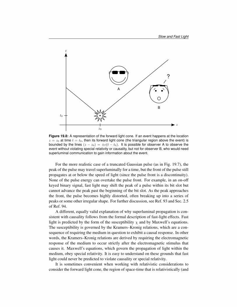
Figure 19.8: A representation of the forward light cone. If an event happens at the locationz = z0 at time t = t0, then its forward light cone (the triangular region above the event) isbounded by the lines (z − z0) = ±c(t − t0). It is possible for observer A to observe theevent without violating special relativity or causality, but not for observer B, who would needsuperluminal communication to gain information about the event.
For the more realistic case of a truncated Gaussian pulse (as in Fig. 19.7), thepeak of the pulse may travel superluminally for a time, but the front of the pulse stillpropagates at or below the speed of light (since the pulse front is a discontinuity).None of the pulse energy can overtake the pulse front. For example, in an on-offkeyed binary signal, fast light may shift the peak of a pulse within its bit slot butcannot advance the peak past the beginning of the bit slot. As the peak approachesthe front, the pulse becomes highly distorted, often breaking up into a series ofpeaks or some other irregular shape. For further discussion, see Ref. 93 and Sec. 2.5of Ref. 94.
A different, equally valid explanation of why superluminal propagation is con-sistent with causality follows from the formal description of fast-light effects. Fastlight is predicted by the form of the susceptibility χ and by Maxwell’s equations.The susceptibility is governed by the Kramers–Kronig relations, which are a con-sequence of requiring the medium in question to exhibit a causal response. In otherwords, the Kramers–Kronig relations are derived by requiring the electromagneticresponse of the medium to occur strictly after the electromagnetic stimulus thatcauses it. Maxwell’s equations, which govern the propagation of light within themedium, obey special relativity. It is easy to understand on these grounds that fastlight could never be predicted to violate causality or special relativity.
It is sometimes convenient when working with relativistic considerations toconsider the forward light cone, the region of space-time that is relativistically (and

Tutorials in Complex Photonic Media
t
zz0 z1
Figure 19.9: Superluminal (fast-light) propagation and the forward light-cone. The front ofthe pulse propagates at c both in vacuum (z < z0 and z > z1) and in the medium (z0 ≤ z ≤z1); the pulse peak travels at c in vacuum and at vg > c within the medium. Although thepeak moves faster than c over a short space-time interval, it does not violate causality: Thepeak cannot escape the forward light cone of the beginning of the transmission event. Inset:The trajectory of the peak of the pulse (dotted line) and that of the pulse front (solid line).See text for details.
causally) accessible from a given point in space-time. In the example shown inFig. 19.8, an event happens at the point z = z0 at the time t = t0. Only observersinside the forward light cone, or inside the boundaries (z−z0) = ±c(t− t0), couldpossibly observe the event. Any other observers would need a form of superluminalcommunication, or information transfer faster than the speed of light.
Imagine now that a long but truncated Gaussian pulse is transmitted through asuperluminal medium, as shown in Fig. 19.9. A fast-light medium exists betweenz = z0 and z = z1. A transmitter at location z = 0 begins transmitting a long buttruncated Gaussian pulse at time t = 0. The forward light cone of the transmissionevent is denoted by the solid line, which also represents the pulse front travelingat its maximum velocity c. The peak of the pulse travels at c in vacuum and atvg > c in the medium. However, the peak can never overtake the front; instead, thepulse would become distorted. (Notice how the pulse expands inside the fast-lightmedium.) The inset to Fig. 19.9 shows the trajectory of the peak (dotted line) andthe trajectory of the front (solid line). Inside the medium, the dotted line’s slope ismore horizontal than the solid line’s slope, meaning that the speed of the peak isgreater than the speed of the front and greater than c in that region. However, thedotted line may never cross the solid line. Fast-light propagation does not violatecausality, because the peak of the pulse can never travel outside of the forward

Slow and Fast Light
light cone of the event that began the transmission of the pulse. (This explanationis similar in spirit to the bit slot argument above.)
A number of other velocities have been defined in an attempt to understandthe relationship between superluminal group velocities and causality. The originalwork of Sommerfeld and Brillouin defined five different velocities, including thefront velocity and the group velocity, and showed that the front velocity is alwaysless than or equal to c (always luminal), even when vg > c. The group delay as-sociated with an evanescent wave can appear superluminal, akin to the Hartmaneffect of quantum-mechanical tunneling through a barrier. However, the effect is amatter of energy storage and retrieval in the medium, rather than true propagation.The group delay of evanescent waves, then, should not be considered a propaga-tion time.95, 96 For propagating waves, an “energy centroid” can be defined (similarto the center of mass for the total electromagnetic and stored material energy); itsvelocity is always luminal.97–99 (Recall that, even in the case of backward light,the energy flow is still in the forward direction.)14 One group attempted to quantifythe information velocity by defining special pulses with definite points of distin-guishability and then tracking the time at which the pulses could be distinguished.They found that the information velocity thus defined was always luminal, even forvg > c.73
As a result of Brillouin’s work, the special theory of relativity was reformulatedslightly in the early 20th century: No information may be communicated fasterthan the speed of light.73 There is no clear consensus on what constitutes the “in-formation velocity” or the “signal velocity,” perhaps due to the lack of a universaldefinition for “information” or for “signal.” However, it has been well establishedthat fast light and backward light cannot violate causality.
19.5 Potential Applications
Slow and fast light allow researchers to conduct many exciting fundamental stud-ies of physics and light propagation, but they also have many potential practicalapplications. The applications proposed for slow and fast light cover many dif-ferent areas, but they can be grouped into three main themes. Perhaps the mostobvious use for a slow-light medium is as a tunable optical delay line, a compactdevice that can store or buffer light pulses for a time or perhaps even indefinitely.Tunable optical delay lines could find a number of applications within telecom-munication networks, as well as in optical coherence tomography (OCT), ultrafastpulse metrology, and various kinds of optical signal processing.100, 101 Slow lightcan also be used to enhance the nonlinear effects of an optical material, leading tosmaller devices and lower operating power in applications that require a high degreeof nonlinearity. Finally, slow and fast light can enhance interferometry, producingmore sensitive and more stable interferometers. (As discussed in Sec. 19.4.4, fastlight may not be used to increase network data rates by increasing the propagationspeed of light above c.)

Tutorials in Complex Photonic Media
buffer
(a)
buffer
(b)
buffer
(c)Figure 19.10: Contention resolution using a packet buffer in a 3×3 network switch. Symbolsindicate packet destinations. (a) Three packets arrive simultaneously at the switch’s inputports. The upper and middle packets are destined for the same output port. (b) The upperand lower packets are routed immediately to their destinations, while the middle packet isstored in a buffer. (c) When the appropriate output port becomes available, the bufferedpacket is released.
19.5.1 Optical delay lines
19.5.1.1 Optical network buffer for all-optical routing
In a packet-based data network, such as the Internet, a router can be modeled as anN ×N switch, as shown in Fig. 19.10. As packets arrive at the router’s input ports,the router reads the destination information in the packets and sends them to theappropriate output ports. However, contention arises when two packets destined forthe same output port arrive simultaneously at the router’s inputs, as in Fig. 19.10(a).The router cannot simultaneously send both packets to the same output port. If ithas no buffer, it can send one packet and must drop (discard) the other packet.Dropped packets must be retransmitted, causing increased network latency.
A much more desirable situation is shown in Fig. 19.10(b). If the router has aninternal packet buffer, as in Fig. 19.10(c), it can send one packet and store the otherin its buffer until the output port becomes available. Buffering enhances networkrobustness and throughput. (Of course, the actual router is much more complex,but this model suffices conceptually. For more details, see Chap. 5 of Ref. 102.)
At present, essentially all routing functions in an optical network are imple-mented in electronics. This requires converting the optical signal to an electrical

Slow and Fast Light
signal for processing and then back to an optical signal for further transmission.This process, known as OEO conversion, adds delay to network transmissions andconsumes additional power. An optical buffer would be the first step in all-opticalnetworking, which many feel will soon become crucial to the increased perfor-mance of telecommunication networks.103
19.5.1.2 Network resynchronization and jitter correction
Tunable optical delay lines are ideal for all-optical jitter compensation.104 In mod-ern data networks, transmissions are synchronized to bit slots, regularly spacedtime windows during which either a zero or one value is transmitted. For example,in traditional on-off keyed (OOK) transmission, zero or one is indicated respec-tively by the absence or presence of a light pulse in each bit slot. In a 10-Gbit/stransmission link, bit slots are 100 ps each. Every 100 ps, the transmitter transmitsa pulse of light to indicate a one or no pulse to indicate a zero.
Transmitters and receivers must agree on the size and start times of bit slots.Sometimes, parts of the data stream become slightly stretched, compressed, orshifted during the transmission process, resulting in a slight desynchronization be-tween the transmitter and receiver. The receiver observes jitter in the data stream,meaning that each data bit arrives slightly before or after the expected time, shiftedby a random amount. In other words, the data bits are not precisely aligned to thebit slots at the receiver.
Jitter is usually caused by random processes such as temperature changes, vi-bration, or pattern-dependent nonlinearities in the transmission medium or equip-ment. It is important that receiver equipment adjust its timing slightly to compen-sate for jitter, or else data corruption and increased bit-error rate (BER) can result.All-optical networks will require all-optical methods of jitter compensation, suchas could be afforded by slow-light and fast-light delay lines.
19.5.1.3 Tapped delay lines and equalization filters
Optical delay lines can be used to implement tapped delay lines, as shown inFig. 19.11(a). Tapped delay lines, in turn, can be used to implement certain op-tical signal processing elements, particularly filters.105 Such filters are prevalent inelectronics and allow reshaping of the signal spectrum in a well-defined manner.A typical filter is shown in Fig. 19.11(b). Optical filters may be particularly usefulfor equalization of an optical signal, whereby certain transmission effects can bemitigated and network robustness enhanced.
19.5.1.4 Optical memory and stopped light for coherent control
The group velocity of light can in fact be adjusted to zero, leading to so-calledstopped light.15, 16, 106 One stopped-light technique is to use electromagneticallyinduced transparency (EIT) to “map” a light pulse onto the spin coherence of a

Tutorials in Complex Photonic Media
(a)
(b)Figure 19.11: (a) An optical tapped delay line. Each block represents a delay element,such as a slow-light element. Each small dot represents a “tap,” possibly implemented by abeamsplitter, that allows a delayed copy of the optical signal to be used. (b) An optical finiteimpulse response (FIR) filter. The cross symbols represent modulation of some kind (suchas by variable attenuators), and the plus symbols represent combination of the signals (suchas by a beamsplitter).
medium, effectively storing the pulse. The pulse can later be retrieved by per-forming the reverse operation. Other proposed techniques include using solitonsin coupled-resonator structures.63, 107 A stopped-light system could be useful as anoptical memory for storing pulses of light.
Many stopped-light techniques also preserve quantum coherence properties.EIT-based techniques, for example, can be used to preserve and store entangle-ment, or the coherence of two quantum-mechanical systems (such as two photonsor a photon and an atom). A so-called quantum memory, one which can store andretrieve entangled photons, could find applications in quantum computing, quan-tum cryptography, and any other technology that depends on entanglement.108
One drawback of stopped-light memories is the finite lifetime of the memory.EIT media gradually undergo decoherence (or dephasing). Other kinds of opticalmemories have different decay mechanisms, but all memories decay and lose theirdata over time. But decay only needs to be slowed, not eliminated. A memorycell can be refreshed by reading out its value and rewriting the value into the cell,starting the decay cycle anew. In two 2001 stopped-light experiments using EIT, thecoherence lifetime was 500 µs.15, 16 Thus, a stopped-light memory cell using similartechniques would need to be refreshed faster than every 500 µs. For comparison,modern electronic memory (DRAM) cells require a refresh every 7.8 µs.109
19.5.1.5 Optical image buffering
Slow-light media can buffer not just pulses of light but in fact entire images.110 Bothamplitude and phase information in an image are preserved by slow-light media.Such an image buffer could have applications in optical image processing.

Slow and Fast Light
19.5.1.6 True time delay for radar and lidar
A phased-array radar antenna is a configuration of many individual antennas thatradiate the same signal, only shifted in time relative to each other. Typically, therelative phases of the individual antenna elements are tuned to steer the radar beamin any direction. The rephasing acts like a time delay for narrowband radar. How-ever, for wideband radar signals, using the signal phases to steer the beam willcause a phenomenon called beam squint, which results in directional inaccuracy.In these cases, a true time delay must be used to offset the signal of each antennaelement.111, 112 There has been much interest in the past in the possibility of opticaltrue time delay for radar, as optical signals can sustain the high bandwidth neededfor modern radar. A radio frequency (RF) signal is impressed on an optical carrier,a tunable optical optical delay line creates the true time delay, and then heterodyneoptical detection is used to reconstruct the delayed RF signal. Slow-light delaylines hold great promise in this area as a tunable source of delay for phased-arrayradar and lidar systems.113
19.5.2 Enhancement of optical nonlinearities
Slow light is sometimes associated with an enhancement of the optical nonlinearity.A reduced group velocity does not of itself increase the nonlinear response. How-ever, in electromagnetically induced transparency (EIT), slow-light effects allowaccess to a kind of latent nonlinearity enhancement (see Sec. 19.2.5). In coupled-resonator structures, the field is enhanced by resonator effects, leading to a nonlin-earity enhancement (see Sec. 19.3.2). Nonlinearity enhancements would let certaindevices be miniaturized and consume less power.
19.5.2.1 Wavelength converter
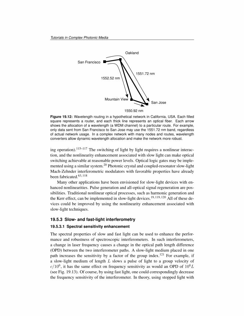
In a wavelength-division multiplexed (WDM) optical network, each of a number ofnetwork channels is carried over the same optical fiber using a different wavelengthrange. One approach to routing the network data is to assign certain wavelengths tocertain routes a priori, such as in Fig. 19.12. However, the network can be far moreflexible and resilient if wavelength assignments can be modified dynamically.114 Awavelength converter is a device that can convert one wavelength channel to an-other wavelength optically and programmably, without decoding and re-encodingthe network data (as in an OEO conversion). The nonlinear optical process offour-wave mixing (FWM) allows just such a conversion to happen. The enhancednonlinearity in a slow-light medium could enable more efficient FWM, allowingboth smaller devices and reduced operating power requirements.20
19.5.2.2 Single-bit optical switching, optical logic, and other applications
Slow-light systems can be used for all-optical network switching at low light levels(i.e., using as little as or less than the equivalent energy of one data bit per switch-
Tutorials in Complex Photonic Media
San Francisco
Oakland
Mountain ViewSan Jose
1552.52 nm1551.72 nm
1550.92 nm
Figure 19.12: Wavelength routing in a hypothetical network in California, USA. Each filledsquare represents a router, and each thick line represents an optical fiber. Each arrowshows the allocation of a wavelength (a WDM channel) to a particular route. For example,only data sent from San Francisco to San Jose may use the 1551.72 nm band, regardlessof actual network usage. In a complex network with many nodes and routes, wavelengthconverters allow dynamic wavelength allocation and make the network more robust.
ing operation).115–117 The switching of light by light requires a nonlinear interac-tion, and the nonlinearity enhancement associated with slow light can make opticalswitching achievable at reasonable power levels. Optical logic gates may be imple-mented using a similar system.20 Photonic crystal and coupled-resonator slow-lightMach-Zehnder interferometric modulators with favorable properties have alreadybeen fabricated.63, 118
Many other applications have been envisioned for slow-light devices with en-hanced nonlinearities. Pulse generation and all-optical signal regeneration are pos-sibilities. Traditional nonlinear optical processes, such as harmonic generation andthe Kerr effect, can be implemented in slow-light devices.19, 119, 120 All of these de-vices could be improved by using the nonlinearity enhancement associated withslow-light techniques.
19.5.3 Slow- and fast-light interferometry
19.5.3.1 Spectral sensitivity enhancement
The spectral properties of slow and fast light can be used to enhance the perfor-mance and robustness of spectroscopic interferometers. In such interferometers,a change in laser frequency causes a change in the optical path length difference(OPD) between the two interferometer paths. A slow-light medium placed in onepath increases the sensitivity by a factor of the group index.121 For example, ifa slow-light medium of length L slows a pulse of light to a group velocity ofc/106, it has the same effect on frequency sensitivity as would an OPD of 106L(see Fig. 19.13). Of course, by using fast light, one could correspondingly decreasethe frequency sensitivity of the interferometer. In theory, using stopped light with

Slow and Fast Light
Laser Beamsplitter
Mirror
Slow-light medium
L
Mirror
Beamsplitter Detector
Figure 19.13: A slow-light Mach–Zehnder interferometer. (Adapted from Ref. 121; used bypermission.)
zero group velocity and zero group index, one could remove all sensitivity of thephase to frequency shifts, at least over the bandwidth of zero group velocity. Usinga medium with a negative group index (in the backward light regime), one couldreverse the sign of the phase change with respect to frequency, although very fewapplications depend on the sign of the phase change. Slow and fast light have alsobeen proposed for use in Fourier-transform interferometry122 and interferometricrotation sensing.123, 124
Similar sensitivity effects to those above are seen when a slow- or fast-lightmedium is placed inside a Fabry–Pérot cavity. The cavity linewidth is changed butthe cavity storage time remains unaffected.125, 126 A slow-light medium narrowsthe cavity linewidth, while a fast-light medium broadens it. Thus, slow light can beused to enhance the spectral resolution of the cavity, while fast light can be used todecrease the sensitivity of the cavity to changes in length or laser frequency.127
19.5.3.2 White light cavities
Fast light may also be used to construct a white light cavity.128 A white light cavityis a Fabry–Pérot cavity that contains an anomalously dispersive (fast-light) element.In a normal Fabry–Pérot cavity, a slight detuning away from resonance will reducethe cavity transmission drastically: Each round trip acquires a slight phase shift,and the multiple round trips add destructively. However, in a white light cavity,the fast-light element compensates for this slight phase shift, such that the cavityresonates across a range of wavelengths. In such a cavity, the electric field is greatlyenhanced, making certain detection problems easier to solve.
The authors gratefully acknowledge financial support by the DARPA/DSO slowlight program and through the NSF.

Tutorials in Complex Photonic Media
References
1. J. Marangos, “Slow light in cool atoms,” Nature 397, 559–560 (1999).
2. L. V. Hau, S. E. Harris, Z. Dutton, and C. H. Behroozi, “Light speed re-duction to 17 metres per second in an ultracold atomic gas,” Nature 397,594–598 (1999).
3. A. Sommerfeld, “Über die Fortpflanzung des Lichtes in dispergierenden Me-dien,” Ann. Phys. 349, 177–202 (1914).
4. L. Brillouin, “Über die Fortpflanzung des Lichtes in dispergierenden Me-dien,” Ann. Phys. 349, 203–240 (1914).
5. N. G. Basov, R. V. Ambartsumyan, V. S. Zuev, P. G. Kryukov, and V. S.Letokhov, “Nonlinear amplification of light pulses,” Sov. Phys. JETP 23, 16–22 (1966).
6. C. G. B. Garrett and D. E. McCumber, “Propagation of a Gaussian light pulsethrough an anomalous dispersion medium,” Phys. Rev. A 1, 305–313 (1970).
7. S. Chu and S. Wong, “Linear pulse propagation in an absorbing medium,”Phys. Rev. Lett. 48, 738–741 (1982).
8. R. W. Boyd and D. J. Gauthier, “ ‘Slow’ and ‘fast’ light,” in Progress inOptics, E. Wolf, Ed., 43, 497–530, Elsevier Science, Amsterdam (2002).
9. R. Y. Chiao and A. M. Steinberg, “Tunneling times and superluminality,” inProgress in Optics, E. Wolf, Ed., 37, 347–406, Elsevier Science, Amsterdam(1997).
10. P. G. Eliseev, H. Cao, C. Liu, G. A. Smolyakov, and M. Osinski, “Nonlinearmode interaction as a mechanism to obtain slow/fast light in diode lasers,” inPhysics and Simulation of Optoelectronic Devices XIV, M. Osinski, F. Hen-neberger, and Y. Arakawa, Eds., Proc. SPIE 6115, 61150U (2006).
11. J. C. Garrison, M. W. Mitchell, R. Y. Chiao, and E. L. Bolda, “Superluminalsignals: Causal loop paradoxes revisited,” Phys. Lett. A 245, 19–25 (1998).
12. A. M. Akulshin, S. Barreiro, and A. Lezama, “Steep anomalous dispersionin coherently prepared Rb vapor,” Phys. Rev. Lett. 83, 4277–4280 (1999).
13. M. González-Herráez, K.-Y. Song, and L. Thévenaz, “Optically controlledslow and fast light in optical fibers using stimulated Brillouin scattering,”Appl. Phys. Lett. 87, 081113 (2005).
14. G. M. Gehring, A. Schweinsberg, C. Barsi, N. Kostinski, and R. W. Boyd,“Observation of backwards pulse propagation through a medium with a neg-ative group velocity,” Science 312, 895–897 (2006).

Slow and Fast Light
15. A. V. Turukhin, V. S. Sudarshanam, M. S. Shahriar, J. A. Musser, B. S. Ham,and P. R. Hemmer, “Observation of ultraslow and stored light pulses in asolid,” Phys. Rev. Lett. 88, 023602 (2001).
16. F. D. Phillips, A. Fleischhauer, A. Mair, R. L. Walsworth, and M. D. Lukin,“Storage of light in atomic vapor,” Phys. Rev. Lett. 86, 783–786 (2001).
17. R. W. Boyd, Nonlinear Optics, Academic Press, Burlington, MA, USA,third ed. (2008).
18. B. E. A. Saleh and M. C. Teich, Fundamentals of Photonics, Wiley–Intersci-ence, New York, second ed. (2007).
19. S. E. Harris and L. V. Hau, “Nonlinear optics at low light levels,” Phys. Rev.Lett. 82, 4611–4614 (1999).
20. M. Soljacic and J. D. Joannopoulos, “Enhancement of nonlinear effects usingphotonic crystals,” Nature Materials 3, 211–219 (2004).
21. S. E. Harris, J. E. Field, and A. Imamoglu, “Nonlinear optical processesusing electromagnetically induced transparency,” Phys. Rev. Lett. 64, 1107–1110 (1990).
22. H. Kang, G. Hernandez, and Y. Zhu, “Superluminal and slow light propaga-tion in cold atoms,” Phys. Rev. A 70, 011801 (2004).
23. M. Phillips and H. Wang, “Spin coherence and electromagnetically inducedtransparency via exciton correlations,” Phys. Rev. Lett. 89, 186401 (2002).
24. S.-W. Chang, S. L. Chuang, C. J. Chang-Hasnain, and H. Wang, “Slow lightusing spin coherence and V-type electromagnetically induced transparencyin [110] strained quantum wells,” J. Opt. Soc. Am. B 24, 849–859 (2007).
25. C. J. Chang-Hasnain and P.-C. Ku, “Variable semiconductor all-optical bufferusing slow light based on electromagnetically induced transparency,” UnitedStates Patent 7,038,827 (2006).
26. S. Ghosh, J. E. Sharping, D. G. Ouzounov, and A. L. Gaeta, “Resonant opti-cal interactions with molecules confined in photonic band-gap fibers,” Phys.Rev. Lett. 94, 093902 (2005).
27. A. K. Patnaik, J. Q. Liang, and K. Hakuta, “Slow light propagation in a thinoptical fiber via electromagnetically induced transparency,” Phys. Rev. A 66,063808 (2002).
28. J. Kim, S. L. Chuang, P.-C. Ku, and C. J. Chang-Hasnain, “Slow light us-ing semiconductor quantum dots,” J. Phys.: Cond. Matt. 16, S3727–S3735(2004).
29. L. Maleki, A. B. Matsko, A. A. Savchenkov, and V. S. Ilchenko, “Tunabledelay line with interacting whispering-gallery-mode resonators,” Opt. Lett.29, 626–628 (2004).

Tutorials in Complex Photonic Media
30. D. D. Smith, H. Chang, K. A. Fuller, A. T. Rosenberger, and R. W. Boyd,“Coupled-resonator-induced transparency,” Phys. Rev. A 69, 063804 (2004).
31. D. D. Smith, N. N. Lepeshkin, A. Schweinsberg, G. Gehring, R. W. Boyd,Q.-H. Park, H. Chang, and D. Jackson, “Coupled-resonator-induced trans-parency in a fiber system,” Opt. Comm. 264, 163–168 (2006).
32. J. D. Franson and S. M. Hendrickson, “Optical transparency using interfer-ence between two modes of a cavity,” Phys. Rev. A 74, 053817 (2006).
33. S. E. Harris, “Electromagnetically induced transparency in an ideal plasma,”Phys. Rev. Lett. 77, 5357–5360 (1996).
34. G. Shvets and J. S. Wurtele, “Transparency of magnetized plasma at the cy-clotron frequency,” Phys. Rev. Lett. 89, 115003 (2002).
35. M. Tushentsov, G. Shvets, A. Yu. Kryachko, and M. D. Tokman, “Undulator-induced transparency of magnetized plasma: New approach to electromag-netic energy compression,” IEEE Trans. Plasma Sci. 33, 23–31 (2005).
36. S. E. Schwarz and T. Y. Tan, “Wave interactions in saturable absorbers,”Appl. Phys. Lett. 10, 4–7 (1967).
37. M. S. Bigelow, N. N. Lepeshkin, and R. W. Boyd, “Observation of ultraslowlight propagation in a ruby crystal at room temperature,” Phys. Rev. Lett. 90,113903 (2003).
38. A. Schweinsberg, N. Lepeshkin, M. S. Bigelow, R. W. Boyd, and S. Jarabo,“Observation of superluminal and slow light propagation in erbium-dopedoptical fiber,” Europhys. Lett. 73, 218–224 (2006).
39. N. G. Basov, R. V. Ambartsumyan, V. S. Zuev, P. G. Kryukov, and V. S.Letokhov, “Propagation velocity of an intense light pulse in a medium withinverse population,” Sov. Phys. Dokl. 10, 1039 (1966).
40. A. C. Selden, “Pulse transmission through a saturable absorber,” Brit. J. Appl.Phys. 18, 743–748 (1967).
41. A. C. Selden, “Analysis of the saturable absorber transmission equation,” J.Phys. D 3, 1935–1943 (1970).
42. M. S. Bigelow, N. N. Lepeshkin, and R. W. Boyd, “Superluminal and slowlight propagation in a room-temperature solid,” Science 301, 200–202 (2003).
43. J. Mørk, R. Kjær, M. van der Poel, and K. Yvind, “Slow light in a semi-conductor waveguide at gigahertz frequencies,” Opt. Express 13, 8136–8145(2005).
44. P. Palinginis, S. Crankshaw, F. Sedgwick, E.-T. Kim, M. Moewe, C. J. Chang-Hasnain, H. Wang, and S.-L. Chuang, “Ultraslow light (< 200 m/s) propaga-tion in a semiconductor nanostructure,” Appl. Phys. Lett. 87, 171102 (2005).

Slow and Fast Light
45. H. Su and S. L. Chuang, “Room temperature slow and fast light in quantum-dot semiconductor optical amplifiers,” Appl. Phys. Lett. 88, 061102 (2006).
46. P.-C. Ku, F. Sedgwick, C. J. Chang-Hasnain, P. Palinginis, T. Li, H. Wang, S.-W. Chang, and S.-L. Chuang, “Slow light in semiconductor quantum wells,”Opt. Lett. 29, 2291–2293 (2004).
47. K. Y. Song, M. Herráez, and L. Thévenaz, “Observation of pulse delayingand advancement in optical fibers using stimulated Brillouin scattering,” Opt.Express 13, 82–88 (2005).
48. Y. Okawachi, M. S. Bigelow, J. E. Sharping, Z. Zhu, A. Schweinsberg, D. J.Gauthier, R. W. Boyd, and A. L. Gaeta, “Tunable all-optical delays via Bril-louin slow light in an optical fiber,” Phys. Rev. Lett. 94, 153902 (2005).
49. M. D. Stenner, M. A. Neifeld, Z. Zhu, A. M. Dawes, and D. J. Gauthier,“Distortion management in slow-light pulse delay,” Opt. Express 13, 9995–10002 (2005).
50. Z. Zhu, A. M. C. Dawes, D. J. Gauthier, L. Zhang, and A. E. Willner, “12-GHz-bandwidth SBS slow light in optical fibers,” in Proceedings of the Op-tical Fiber Communication Conference, paper PDP1, IEEE, Piscataway, NJ,USA (2006).
51. K. Lee and N. M. Lawandy, “Optically induced pulse delay in a solid-stateRaman amplifier,” Appl. Phys. Lett. 78, 703–705 (2001).
52. F. L. Kien, J. Q. Liang, and K. Hakuta, “Slow light produced by far-off-resonance Raman scattering,” J. Sel. Topics Quantum Electron. 9, 93–101(2003).
53. J. Sharping, Y. Okawachi, and A. Gaeta, “Wide bandwidth slow light usinga Raman fiber amplifier,” Opt. Express 13, 6092–6098 (2005).
54. R. M. Camacho, M. V. Pack, J. C. Howell, A. Schweinsberg, and R. W.Boyd, “Wide-bandwidth, tunable, multiple-pulse-width optical delays usingslow light in cesium vapor,” Phys. Rev. Lett. 98, 153601 (2007).
55. X. Zhao, P. Palinginis, B. Pesala, C. J. Chang-Hasnain, and P. Hemmer, “Tun-able ultraslow light in vertical-cavity surface-emitting laser amplifier,” Opt.Express 13, 7899–7904 (2005).
56. K. Ogawa, T. Katsuyama, and H. Nakamura, “Time-of-flight measurementof excitonic polaritons in a GaAs/AlGaAs quantum well,” Appl. Phys. Lett.53, 1077–1079 (1988).
57. N. Shaw, W. Stewart, J. Heaton, and D. Wight, “Optical slow-wave resonantmodulation in electro-optic GaAs/AlGaAs modulators,” Electron. Lett. 35,1557–1558 (1999).

Tutorials in Complex Photonic Media
58. P.-C. Ku, C. J. Chang-Hasnain, and S. L. Chuang, “Variable semiconductorall-optical buffer,” Electron. Lett. 38, 1581–1583 (2002).
59. C. J. Chang-Hasnain, P.-C. Ku, J. Kim, and S.-L. Chuang, “Variable opticalbuffer using slow light in semiconductor nanostructures,” Proc. IEEE 91,1884–1897 (2003).
60. P.-C. Ku, C. J. Chang-Hasnain, and S. L. Chuang, “Slow light in semicon-ductor heterostructures,” J. Phys. D 40, R93–R107 (2007).
61. G. P. Agrawal, Lightwave Technology: Components and Devices, Wiley–Interscience, New York (2004).
62. J. K. S. Poon, J. Scheuer, Y. Xu, and A. Yariv, “Designing coupled-resonatoroptical waveguide delay lines,” J. Opt. Soc. Am. B 21, 1665–1673 (2004).
63. J. Scheuer, G. T. Paloczi, J. K. S. Poon, and A. Yariv, “Coupled resonatoroptical waveguides: Toward the slowing & storage of light,” Opt. & Photon.News 16, 36–40 (2005).
64. Y. Chen and S. Blair, “Nonlinearity enhancement in finite coupled-resonatorslow-light waveguides,” Opt. Express 12, 3353–3366 (2004).
65. G. Lenz, B. J. Eggleton, C. K. Madsen, and R. E. Slusher, “Optical delaylines based on optical filters,” J. Quantum Electron. 37, 525–532 (2001).
66. J. B. Khurgin, “Light slowing down in Moiré fiber gratings and its implica-tions for nonlinear optics,” Phys. Rev. A 62, 013821 (2000).
67. E. Yablonovitch and T. J. Gmitter, “Photonic band structure: The face-cen-tered-cubic case,” Phys. Rev. Lett. 63, 1950–1953 (1989).
68. S. John and J. Wang, “Quantum optics of localized light in a photonic bandgap,” Phys. Rev. B 43, 12772–12789 (1991).
69. J. M. Bendickson, J. P. Dowling, and M. Scalora, “Analytic expressions forthe electromagnetic mode density in finite, one-dimensional, photonic band-gap structures,” Phys. Rev. E 53, 4107–4121 (1996).
70. M. Scalora, R. J. Flynn, S. B. Reinhardt, R. L. Fork, M. J. Bloemer, M. D.Tocci, C. M. Bowden, H. S. Ledbetter, J. M. Bendickson, J. P. Dowling,and R. P. Leavitt, “Ultrashort pulse propagation at the photonic band edge:Large tunable group delay with minimal distortion and loss,” Phys. Rev. E54, R1078–R1081 (1996).
71. M. L. Povinelli, S. Johnson, and J. D. Joannopoulos, “Slow-light, band-edgewaveguides for tunable time delays,” Opt. Express 13, 7145–7159 (2005).
72. L. J. Wang, A. Kuzmich, and A. Dogariu, “Gain-assisted superluminal lightpropagation,” Nature 406, 277–279 (2000).

Slow and Fast Light
73. M. D. Stenner, D. J. Gauthier, and M. A. Neifeld, “The speed of informationin a ‘fast-light’ optical medium,” Nature 425, 695–698 (2003).
74. R. M. Camacho, M. V. Pack, and J. C. Howell, “Low-distortion slow lightusing two absorption resonances,” Phys. Rev. A 73, 063812 (2006).
75. Z. Shi, R. Pant, Z. Zhu, M. D. Stenner, M. A. Neifeld, D. J. Gauthier, andR. W. Boyd, “Design of a tunable time-delay element using multiple gainlines for increased fractional delay with high data fidelity,” Opt. Lett. 32(14),1986–1988 (2007).
76. H. Shin, A. Schweinsberg, G. Gehring, K. Schwertz, H. J. Chang, R. W.Boyd, Q.-H. Park, and D. J. Gauthier, “Reducing pulse distortion in fast-light pulse propagation through an erbium-doped fiber amplifier,” Opt. Lett.32, 906–908 (2007).
77. J. K. S. Poon, L. Zhu, G. A. Rose, and A. Yariv, “Polymer microring coupled-resonator optical waveguides,” J. Lightwave Technol. 24, 1843–1849 (2006).
78. R. W. Boyd, D. J. Gauthier, A. L. Gaeta, and A. E. Willner, “Maximum timedelay achievable on propagation through a slow-light medium,” Phys. Rev. A71, 023801 (2005).
79. R. S. Tucker, P.-C. Ku, and C. J. Chang-Hasnain, “Delay-bandwidth productand storage density in slow-light optical buffers,” Electron. Lett. 41, 208–209(2005).
80. M. Fleischhauer and M. D. Lukin, “Quantum memory for photons: Dark-state polaritons,” Phys. Rev. A 65, 022314 (2002).
81. P. Ginzburg and M. Orenstein, “Slow light and voltage control of group ve-locity in resonantly coupled quantum wells,” Opt. Express 14, 12467–12472(2006).
82. R. S. Tucker, P.-C. Ku, and C. J. Chang-Hasnain, “Slow-light optical buffers:Capabilities and fundamental limitations,” J. Lightwave Technol. 23, 4046–4066 (2005).
83. B. Zhang, L. Yan, I. Fazal, L. Zhang, A. E. Willner, Z. Zhu, and D. J. Gau-thier, “Slow light on Gbit/s differential-phase-shift-keying signals,” Opt. Ex-press 15, 1878–1883 (2007).
84. E. Shumakher, N. Orbach, A. Nevet, D. Dahan, and G. Eisenstein, “On thebalance between delay, bandwidth and signal distortion in slow light systemsbased on stimulated Brillouin scattering in optical fibers,” Opt. Express 14,5877–5884 (2006).
85. M. D. Lukin and A. Imamoglu, “Controlling photons using electromagneti-cally induced transparency,” Nature 413, 273–276 (2001).

Tutorials in Complex Photonic Media
86. S. E. Harris, J. E. Field, and A. Kasapi, “Dispersive properties of electromag-netically induced transparency,” Phys. Rev. A 46, R29–R32 (1992).
87. M. G. Payne, L. Deng, and K. J. Jiang, “Limitations of steady state solutionsto a two-state model of population oscillations and hole burning,” Phys. Rev.A 74, 043810 (2006).
88. D. C. Roberts, T. Gasenzer, and K. Burnett, “Limitations of light delay andstorage times in electromagnetically induced transparency experiments withcondensates,” Phys. Rev. A 66, 023801 (2002).
89. A. Matsko, D. Strekalov, and L. Maleki, “On the dynamic range of opticaldelay lines based on coherent atomic media,” Opt. Express 13, 2210–2223(2005).
90. J. D. Jackson, Classical Electrodynamics, John Wiley & Sons, New York,third ed. (1999).
91. G. Diener, “Superluminal group velocities and information transfer,” Phys.Lett. A 223, 327–331 (1996).
92. A. Icsevgi and W. E. Lamb, “Propagation of light pulses in a laser amplifier,”Phys. Rev. 185, 517–545 (1969).
93. D. J. Gauthier and R. W. Boyd, “Fast light, slow light and optical precursors:What does it all mean?” Photon. Spectra 41, 82–90 (2007).
94. P. W. Milonni, Fast Light, Slow Light, and Left-Handed Light, Taylor & Fran-cis, New York (2005).
95. H. G. Winful, “Energy storage in superluminal barrier tunneling: Origin ofthe ‘Hartman effect’,” Opt. Express 10, 1491–1496 (2002).
96. H. G. Winful, “Nature of ‘superluminal’ barrier tunneling,” Phys. Rev. Lett.90, 023901 (2003).
97. S. Glasgow, M. Ware, and J. Peatross, “Poynting’s theorem and luminal totalenergy transport in passive dielectric media,” Phys. Rev. E 64, 046610 (2001).
98. M. Ware, S. Glasgow, and J. Peatross, “Role of group velocity in trackingfield energy in linear dielectrics,” Opt. Express 9, 506–518 (2001).
99. J. Peatross, M. Ware, and S. Glasgow, “Role of the instantaneous spectrumon pulse propagation in causal linear dielectrics,” J. Opt. Soc. Am. A 18,1719–1725 (2001).
100. J. E. Sharping, Y. Okawachi, J. van Howe, C. Xu, Y. Wang, A. E. Willner, andA. L. Gaeta, “All-optical, wavelength and bandwidth preserving, pulse delaybased on parametric wavelength conversion and dispersion,” Opt. Express13, 7872–7877 (2005).

Slow and Fast Light
101. Y. Okawachi, J. E. Sharping, C. Xu, and A. L. Gaeta, “Large tunable opticaldelays via self-phase modulation and dispersion,” Opt. Express 14, 12022–12027 (2006).
102. A. S. Tanenbaum, Computer Networks, Prentice Hall, Upper Saddle River,NJ, USA, fourth ed. (2003).
103. J. R. Lowell and E. Parra, “Applications of slow light: A DARPA perspec-tive,” in Advanced Optical and Quantum Memories and Computing II, H. J.Coufal, Z. U. Hasan, and A. E. Craig, Eds., Proc. SPIE 5735, 80–86 (2005).
104. B. Zhang, L. Zhang, L.-S. Zhang, I. Fazal, J.-Y. Yang, and A. E. Willner,“Continuously-tunable, bit-rate variable OTDM using broadband SBS slow-light delay line,” Opt. Express 15, 8317–8322 (2007).
105. C. Yu, T. Luo, L. Zhang, and A. E. Willner, “Data pulse distortion induced bya slow-light tunable delay line in optical fiber,” Opt. Lett. 32, 20–22 (2007).
106. M. D. Lukin, S. F. Yelin, and M. Fleischhauer, “Entanglement of atomicensembles by trapping correlated photon states,” Phys. Rev. Lett. 84, 4232–4235 (2000).
107. S. Mookherjea and A. Yariv, “Kerr-stabilized super-resonant modes in cou-pled-resonator optical waveguides,” Phys. Rev. E 66, 046610 (2002).
108. M. Fleischhauer and M. D. Lukin, “Quantum memory for photons: Dark-state polaritons,” Phys. Rev. A 65, 022314 (2002).
109. JEDEC Standard No. 79-2E: DDR2 SDRAM specification, 78. JEDEC SolidState Technology Association, Arlington, VA, USA (2008).
110. R. M. Camacho, C. J. Broadbent, I. Ali-Khan, and J. C. Howell, “All-opticaldelay of images using slow light,” Phys. Rev. Lett. 98, 043902 (2007).
111. M. I. Skolnik, Radar Handbook, 13.1–13.51. McGraw-Hill, New York,third ed. (2008).
112. I. Frigyes and A. J. Seeds, “Optically generated true-time delay in phased-array antennas,” IEEE Trans. Micro. Theory Tech. 43, 2378–2386 (1995).
113. H. Su, P. Kondratko, and S. L. Chuang, “Variable optical delay using popula-tion oscillation and four-wave-mixing in semiconductor optical amplifiers,”Opt. Express 14, 4800–4807 (2006).
114. J. M. Yates, J. P. R. Lacey, D. Everitt, and M. Summerfield, “Limited-rangewavelength translation in all-optical networks,” in INFOCOM ’96: FifteenthAnnual Joint Conference of the IEEE Computer and Communications Soci-eties, 3, 954–961 (1996).
115. H. Schmidt and R. J. Ram, “All-optical wavelength converter and switchbased on electromagnetically induced transparency,” Appl. Phys. Lett. 76,3173–3175 (2000).

Tutorials in Complex Photonic Media
116. D. A. Braje, V. Balic, G. Y. Yin, and S. E. Harris, “Low-light-level nonlinearoptics with slow light,” Phys. Rev. A 68, 041801 (2003).
117. A. M. C. Dawes, L. Illing, S. M. Clark, and D. J. Gauthier, “All-opticalswitching in rubidium vapor,” Science 308, 672–674 (2005).
118. Yu. A. Vlasov, M. O’Boyle, H. F. Hamann, and S. J. McNab, “Active controlof slow light on a chip with photonic crystal waveguides,” Nature 438, 65–69(2005).
119. M. Soljacic, S. G. Johnson, S. Fan, M. Ibanescu, E. P. Ippen, and J. D.Joannopoulos, “Photonic-crystal slow-light enhancement of nonlinear phasesensitivity,” J. Opt. Soc. Am. B 19, 2052–2059 (2002).
120. Z. Yang, P. Chak, R. Iyer, A. D. Bristow, J. E. Sipe, J. S. Aitchison, H. M. vanDriel, and A. L. Smirl, “Enhanced second harmonic generation using slowlight in AlGaAs microring resonators,” in Slow and Fast Light, paper MB6,OSA, Washington, DC, USA (2006).
121. Z. Shi, R. W. Boyd, D. J. Gauthier, and C. C. Dudley, “Enhancing the spectralsensitivity of interferometers using slow-light media,” Opt. Lett. 32, 915–917(2007).
122. Z. Shi, R. W. Boyd, R. M. Camacho, P. K. Vudyasetu, and J. C. Howell,“Slow-light Fourier transform interferometer,” Phys. Rev. Lett. 99, 240801(2007).
123. M. S. Shahriar, G. S. Pati, R. Tripathi, V. Gopal, M. Messall, and K. Salit,“Ultrahigh enhancement in absolute and relative rotation sensing using fastand slow light,” Phys. Rev. A 75, 053807 (2007).
124. M. Salit, G. S. Pati, K. Salit, and M. S. Shahriar, “Fast-light for astrophysics:Super-sensitive gyroscopes and gravitational wave detectors,” J. Mod. Opt.54, 2425–2440 (2007).
125. G. S. Pati, M. Salit, K. Salit, and M. S. Shahriar, “Demonstration of a tunable-bandwidth white-light interferometer using anomalous dispersion in atomicvapor,” prl 99, 133601 (2007).
126. G. S. Pati, M. Salit, K. Salit, and M. S. Shahriar, “Demonstration of tunabledisplacement-measurement-sensitivity using variable group index in a ringresonator,” oc 281, 4931–4935 (2008).
127. M. S. Shahriar, G. S. Pati, M. Messall, and K. R. Salit, “Slow-light basedcontrol of interferometer sensitivity,” in Frontiers in Optics/Laser ScienceXXII, paper LTuJ4, OSA, Washington, DC, USA (2006).
128. A. Wicht, K. Danzmann, M. Fleischhauer, M. Scully, G. Müller, and R.-H.Rinkleff, “White-light cavities, atomic phase coherence, and gravitationalwave detectors,” Opt. Comm. 134, 431–439 (1997).

Slow and Fast Light
Biographies
Joseph E. Vornehm, Jr. received his B.S. degree in electrical engineering fromNortheastern University (Boston, MA, USA) in 2001. After several years as anengineer in the Signal Processing Department of The MITRE Corporation (Bed-ford, MA, USA), he attended Northwestern University (Evanston, IL, USA) andreceived his M.S. degree in electrical engineering in 2005. His master’s thesis, ti-tled “Multi-spectral Raman gain in dual-isotope rubidium vapor,” was supervisedby Selim Shahriar. He is currently a Ph.D. student in the Nonlinear Optics groupat the Institute of Optics of the University of Rochester, where he is a Sproull Fel-low. His research interests include practical applications of slow and fast light. Joeis a student member of SPIE, the Optical Society of America, and the AmericanPhysical Society, and a he is a member of the IEEE.
Professor Robert W. Boyd received his B.S. degree in Physics from the Massachu-setts Institute of Technology in 1969 and received his Ph.D. degree in Physics in1977 from the University of California at Berkeley. His Ph.D. thesis was super-vised by Professor Charles H. Townes and involved the use of nonlinear opticaltechniques for infrared detection for astronomy. Professor Boyd joined the facultyof the Institute of Optics of the University of Rochester in 1977 and is presentlythe M. Parker Givens Professor of Optics and Professor of Physics. His researchinterests include slow and fast light, optical physics, nonlinear optical interactions,nonlinear optical properties of materials, and applications of nonlinear optics in-cluding quantum and nonlinear optical imaging. Professor Boyd is a Fellow of theOptical Society of America and the American Physical Society and a member ofSPIE and IEEE/LEOS. He is author of Radiometry and the Detection of OpticalRadiation (1983) and Nonlinear Optics (1992), and he is co-editor of Optical In-stabilities (1986) and Contemporary Nonlinear Optics (1992). Professor Boyd haspublished more than 250 research papers, has been awarded seven U.S. patents, andhas supervised the Ph.D. theses of 29 students.

Index
anomalous dispersion, 6atomic vapors
slow light in, 15
backward light, 7causality and, 7, 19energy flow of, 7
band-edge dispersion, 17bit-error rate (BER)
in slow-light systems, 18, 24
causality, 8, 19–22coherent control
in EIT slow-light systems, 12, 24–25
coherent population oscillation (CPO),12–13, 18
slow light in, 13coupled resonators
slow light in, 15–17, 26, 27critically anomalous dispersion, 6
decoherencein EIT slow-light systems, 18, 25
delay–bandwidth product (DBP), 18dispersion, 6, 9, 10
electromagnetically induced transparency(EIT), 12, 18, 24, 26
energy densityenhancement, in slow light, 10
eye opening, 18
fast light, 6causality and, 6, 19due to absorption line, 9–10
Fourier-transform interferometer (FTI),28
fractional advancement, 17fractional delay, 17, 18front velocity, 19, 22
group delay, 5, 17, 18group index, 6, 10, 17group velocity, 2–6, 10, 18, 19, 22group velocity dispersion (GVD), 6,
18
higher-order dispersion, 6, 18
image buffering, 25image processing
slow light and, 25information velocity, 19, 22interferometer
slow-light-enhanced, 27–28
jitter, 24
Kramers–Kronig relations, 6, 8–9, 17,20
lidar, 26Lorentz model, 9
nonlinearity enhancementin slow light systems, 12, 16, 26,
27normal dispersion, 6
optical delay line, 23optical fibers
slow light in, 13, 14
39

INDEX
optical logic, 26optical memory, 18, 24–25optical networking
slow light and, 18, 23–24, 26optical switching, 26optical-electrical-optical (OEO) con-
version, 24
phase velocity, 2–3phased-array radar, 26photonic crystals
slow light in, 15–16, 27polarization density, 8pulse broadening, 17pulse compression, 17pulse distortion, 5–6, 10, 14, 17, 19,
20measures of, 18
pulse spatial compression, 10–11pulse velocity, 3, 6
quantum coherencein EIT slow-light systems, 12, 25
radar, 26refractive index, 3, 4, 6, 8, 10relativity, 19–22resonance, 9–10, 14rotation-sensing interferometer, 28
saturable absorption, 13semiconductors
slow light in, 13, 15signal velocity, 22slow light
definition, 6due to gain line, 9–10energy density enhancement, 10–
11in atomic vapors, 15in coupled resonators, 15–17, 26,
27in optical fibers, 13, 14in photonic crystals, 15–16, 27
in semiconductors, 13, 15in solid-state media, 13, 14spatial compression of pulses, 10–
11slow-light interferometry, 27–28slowing factor, 17solid-state media
slow light in, 13, 14spatial pulse compression, 10–11spectral interferometer, 27spin coherence, 7, 24stimulated Brillouin scattering (SBS),
13–14, 18stimulated Raman scattering (SRS), 13–
14stopped light, 7, 24–25storage lifetime, 18, 25superluminal
communication, 6, 22propagation, 6, 19–22
susceptibility, 8–10, 20
true time delay, 26tunneling
superluminal, is not propagation,22
waveguide dispersion, 15wavelength conversion, 26wavelength routing, 26white light cavity, 28


![Mid-infrared photonic crystal cavities · Mid-infrared photonic devices could be used to create miniaturised sensitive detectors for these gases[3]. High-power nonlinear optics devices](https://img.pdfslide.us/doc/110x75/5fa726d81269b625b8019fc5/mid-infrared-photonic-crystal-cavities-mid-infrared-photonic-devices-could-be-used.jpg)