Embed Size (px)
Citation preview
NLR-TP-2001-538
Tutorial on Single- and Two-ComponentTutorial on Single- and Two-ComponentTutorial on Single- and Two-ComponentTutorial on Single- and Two-ComponentTwo-Phase Flow and Heat Transfer:Two-Phase Flow and Heat Transfer:Two-Phase Flow and Heat Transfer:Two-Phase Flow and Heat Transfer:Commonality and DifferenceCommonality and DifferenceCommonality and DifferenceCommonality and Difference
A.A.M. Delil
NationaalNationaalNationaalNationaal Lucht- en Ruimtevaartlaboratorium Lucht- en Ruimtevaartlaboratorium Lucht- en Ruimtevaartlaboratorium Lucht- en RuimtevaartlaboratoriumNational Aerospace Laboratory NLR
NLR-TP-2001-538
Tutorial on Single- and Two-ComponentTutorial on Single- and Two-ComponentTutorial on Single- and Two-ComponentTutorial on Single- and Two-ComponentTwo-Phase Flow and Heat Transfer:Two-Phase Flow and Heat Transfer:Two-Phase Flow and Heat Transfer:Two-Phase Flow and Heat Transfer:Commonality and DifferenceCommonality and DifferenceCommonality and DifferenceCommonality and Difference
A.A.M. Delil
Tutorial presented in the Fundamentals of Two-Phase Flow and Heat Transfer Session ofthe Conference on Thermophysics in Microgravity, held during the Space Technology &Applications International Forum in Albuquerque, USA, 3-7 February 2002. Thecorresponding viewgraphs have been published in the proceedings of the InternationalTwo-Phase Thermal Control Technology Workshop, El Segundo, USA, 7-8 June 2001.
The contents of this report may be cited on condition that full credit is given to NLR andthe author.
Division: SpaceIssued: 27 November 2001Classification of title: Unclassified
-2-NLR-TP-2001-538
Contents
ABSTRACT 3
INTRODUCTION 3
BACKGROUND 3
TWO-PHASE FLOW & HEAT TRANSFER ISSUES 6
Flow Pattern Issues 6
Thermal-Gravitational Modelling & Scaling Issues 7
Pressure Drop 9
Flashing 10
CONCLUSIONS 10
REFERENCES 10
NOMENCLATURE 11
10 Figures
(11 pages in total)
-3-NLR-TP-2001-538
Tutorial on Single- and Two-Component Two-Phase Flowand Heat Transfer: Commonality and Difference
A.A.M. Delil
National Aerospace Laboratory NLRP.O. Box 153, 8300 AD Emmeloord, The Netherlands
Phone +31 527 248229, Fax +31 527 248210, [email protected]
Abstract. It is assessed to what extent the results of two-phase two-component flow and heat transfer research can beusefully applied to support research on the flow and heat transfer in two-phase single-component systems. The latter single-component two-phase systems, envisaged for spacecraft thermal control applications, are Mechanically Pumped andVapour Pressure Driven Loops, Capillary Pumped Loops, and Loop Heat Pipes. In these single-component systems theworking fluid is a mixture of a liquid (for example ammonia, carbon dioxide, ethanol, or other refrigerants, etc.) and itssaturated vapour. The two-component systems considered consist of liquid-gas mixtures, e.g. water-air. Various aspects arediscussed qualitatively and quantitatively to determine commonality and difference between two physically looking similarand close, but essentially different systems. It is focused on the different pressure gradient constituents and total pressuregradients, on flow regime mapping (including evaporating and condensing flow trajectories in the flow pattern maps), onadiabatic flow and the impact of flashing, and on thermal-gravitational scaling issues. It is elucidated that, though there is acertain degree of commonality, the differences are appreciable. The conclusion is that one shall be very careful ininterpreting two-component outcomes to develop single-component two-phase thermal control systems.
INTRODUCTION
Multiphase flow, the simultaneous flow of the different phases (states of matter) gas, liquid and solid, strongly dependson the level and direction of gravitation, since these influence the spatial distribution of the phases, having differentdensities. Of major interest for aerospace applications are the more complicated liquid-vapour or liquid-gas flows, thatare characteristic for aerospace thermal control systems, life sciences systems and propellant systems. Especially forliquid-vapour flow in aerospace two-phase thermal control systems, the phenomena are extremely complicated, becauseof heat and mass exchange between the two phases by evaporation, condensation or flashing. Though a huge amount ofpublications discuss two-phase flow and heat transfer, publications on the impact of reduced gravity and supergravity arevery scarce. This is the main driver to do research on the impact of various gravity levels.
The various heat and mass transfer research issues of two-phase heat transport technology for space applications arediscussed in the next chapters. It is focused on the most complicated case of liquid-vapour flow with heat and massexchange. Simpler cases, like adiabatic or isothermal liquid-vapour flow or liquid-gas flow, can straightforwardly bederived from this liquid-vapour case, as various terms in the constitutive equations can be set zero.
The discussions start with the background of the research, followed by a short general description of two-phase flow andheat transfer phenomena. The impact of the gravity level will be assessed. The discussions focus on developmentsupporting theoretical work (thermal/gravitational scaling of two-phase flow and heat transport in two-phase thermalcontrol loops, including aspects of gravity level dependent two-phase flow pattern mapping and condensation), in-orbittechnology demonstration experiments, and some current R&D. They are concluded by the subject of this tutorial, beingcommonality and difference in single- and two-component two-phase flow and heat transfer.
BACKGROUND
A thermal utility or thermal bus is a pumped fluid, high-capacity heat transport system, serving as a commontemperature controlled heat sink or source to more than one payload, usually to many payloads. Such thermalmanagement systems for future large spacecraft have to transport large amounts of dissipated power (gathered atmany dissipating stations) over large distances to the heat sinks, the radiator(s), where the heat is radiated to the coldspace environment. Pumping pressures can be achieved by mechanical (powered) pumps, capillary action or othermeans, like osmotic pumps or compressors (Almgren, 1981; Stalmach, 1982; Delil, 1984, 1995). Conventional single-phase thermal busses are mechanically pumped. They are based on the heat capacity of the working fluid, they aresimple, well understood, easy to test, inexpensive and low risk. A very serious disadvantage is the required preciseordering of the modules in the thermal circuit. Changes in location or heat load of any individual module (station) will
-4-NLR-TP-2001-538
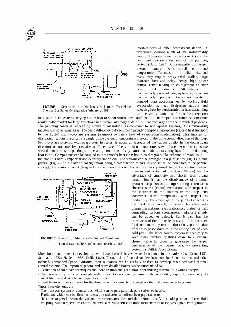
interfere with all other downstream stations. Aprescribed, desired width of the isothermalityband of the system (and its components) and theheat load determine the size of the pumpingsystem (Delil, 1984). Consequently, for properthermal control with small end-to-endtemperature differences to limit radiator size andmass, they require heavy thick walled, largediameter lines and noisy, heavy, high powerpumps, hence leading to enlargement of solararrays and radiators. Alternatives formechanically pumped single-phase systems aremechanically pumped two-phase systems,pumped loops accepting heat by working fluidevaporation at heat dissipating stations andreleasing heat by condensation at heat demandingstations and at radiators, for the heat rejection
into space. Such systems, relying on the heat of vaporisation, have small end-to-end temperature differences (operatenearly isothermally) for large variations in direction and magnitude of the heat exchange with the individual payloads.The pumping power is reduced by orders of magnitude (as compared to single-phase systems), thus minimisingradiator and solar array sizes. The basic difference between mechanically pumped single-phase (caloric heat transportby the liquid) and two-phase systems (transport by latent heat of evaporation/condensation). This implies fordissipating stations in series in a single-phase system a temperature increase in the downstream direction of the loop.For two-phase systems, with evaporators in series, it means an increase of the vapour quality in the downstreamdirection, accompanied by a (usually small) decrease of the saturation temperature. A two-phase thermal bus can serveseveral modules by, depending on operating conditions of any particular module, extracting heat from or dumpingheat into it. Components can be coupled to it to transfer heat from hot to cold regions. The ordering of modules inthe circuit is hardly important and certainly not crucial. The stations can be arranged in a pure series (Fig. 1), a pureparallel (Fig. 2), or in a hybrid configuration, being a combination of parallel and series. As compared to the parallelconcept, the series concept (originally an ammonia, serial thermal bus was planned to be the central thermal
management system of the Space Station) has theadvantage of simplicity and shorter total pipinglength. But it has the disadvantage of a largerpressure drop (unless a larger piping diameter ischosen), some (minor) restrictions with respect tothe sequence of the stations in the loop, andsomewhat more complexity with respect tomodularity. The advantage of the parallel concept isthe modular approach, in which branches withdissipating stations (evaporators/cold plates) or heatdemanding stations (condensers/ radiators) simplycan be added or deleted. But it also has thedrawbacks of the tubing length, and of the complexfeedback control system to adjust the vapour qualityof the two-phase mixture in the exiting line of eachcold plate. The latter control system is necessary tokeep these mixture qualities close to a certain,chosen value in order to guarantee the properperformance of the thermal bus, by preventingsystem instabilities/oscillations.
Most important issues in developing two-phase thermal busses were formulated in the early 80’s (Oren, 1981;Stalmach, 1982; Haslett, 1983; Delil, 1984). Though they focused on developments for Space Station and othermanned/ unmanned Space Platforms, their outcomes can be usefully applied to develop other dedicated thermalcontrol systems. The important general and more detailed issues can be summarised by:- Evaluation of candidate techniques and identification and generation of promising thermal utility/bus concepts.- Comparison of promising concepts with respect to mass, sizing, complexity, reliability, required redundancy (to
meet lifetime and maintenance specifications).- Identification of critical items for the three principle elements of two-phase thermal management systems.These three elements are:- The transport system or thermal bus, which can be pure parallel, pure series, or hybrid.- Radiators, which can be direct condensation radiators or indirect heat pipe radiators.- Heat exchangers between the various instruments/modules and the thermal bus: Via a cold plate or a direct fluid
coupling, via a temperature-controlled enclosure, via a self-contained instrument fluid loop/cold plate configuration.
FIGURE 1. Schematic of a Mechanically Pumped Two-PhaseThermal Bus Series Configuration (Almgren, 1981).
FIGURE 2. Schematic of Mechanically Pumped Two-Phase
Thermal Bus Parallel Configuration (Haslett, 1983).
-5-NLR-TP-2001-538
Major critical items were called to be: The development of reliable mechanical and capillary pumps, and getting a betterunderstanding of two-phase flow and heat transfer in micro-gravity. These aspects of two-phase technology developmentissues were investigated in the last 17 years, by NLR or with NLR involvement. An overview (Delil, 2001), containingmore than 100 references to relevant NLR publications, summarises these NLR activities that include research on:- The impact of gravity level and direction on two-phase flow and heat transfer.- Thermal/gravitational modelling and scaling of two-phase heat transport systems and system components.- Modelling of the two-phase pressure drop as a function of the vapour quality.- The development of two-phase (R114, NH3, ethanol, and CO2) test rigs for experimentation and calibration of
components developed (vapour quality sensors, a high-efficiency low pressure drop condenser, (in)direct radiators.- Development and testing of two-phase heat transport systems for the in-orbit demonstration of two-phase technology,
and the evaluation of flight results: ESA’s In-Orbit Technology Demonstration TPX (Delil, 1995) and the Loop HeatPipe Flight eXperiment (Bienert, 1998), conducted by a team led by Dynatherm, consisting of the Naval ResearchLaboratory and two USAF Laboratories, BMDO, three NASA Institutes, Hughes Space & Communications, and NLR.
Two-phase thermal control systems have reached a certain level of maturity and they are becoming more and moreaccepted as reliable heat transport systems. However, the design of a two-phase flow loop is still rather difficult andcumbersome due to the character of two-phase single-component flow dynamics and heat transfer. In the two-phaselines of mechanically pumped loops and in the condenser of any two-phase loop, the flow pattern dependent heattransfer is of great importance for the definition of a particular thermal management system.
Two very important near-future mechanically pumped two-phase heat transport system applications are:- The two-phase ammonia thermal control system of the Russian segment of the International Space Station, ISS
(Grigoriev, 1999; Cykhotsky, 1999; Leontiev, 1997).- The hybrid two-phase carbon dioxide thermal control loop of the AMS-2 Tracker Thermal Control System (Delil,
2001). AMS-2, the Alpha Magnetic Spectrometer experiment planned for a five years mission as attached payloadon ISS, is an international experiment searching for anti-matter, dark and missing matter. AMS-2, an improvedversion of AMS-1 flown on STS 91, consists of different particle detector systems, one is the Tracker.
Concerning this Tracker Thermal Control System (TTCS) it is remarked that:- In mechanically pumped two-phase loops, the flow pattern dependent heat transfer coefficient for convective flow
boiling is reported to be between say 4 and 5 kW/m2.K (Carey, 1992). This is not true for refrigerants (to be used inthe TTCS) at qualities below 0.15 for which the value can increase to say 20 kW/m2.K at qualities of less than 0.03(Kandlikar, 1989). Data from experiments with CO2 in small diameter tubes confirm this (Pettersen, 2000). Theabove implies that a mechanically pumped system has to be designed such that any evaporator exit quality is below0.15 (preferably even much lower) for efficiency reasons.
- In the case of very lengthy lines in mechanically pumped two-phase loops the pressure (saturated temperature)gradient has to be kept small to guarantee a small end-to-end pressure (saturated temperature) difference to meet therequested isothermality, and to keep the evaporator exit vapour quality below 0.15, as in flowing refrigerants thevapour quality usually increases with pressure decay (Delil, 1992). Ethane is an exception: Quality increases belowsay 0.7, but decreases above 0.7. This issue (called flashing) will be discussed in a later chapter, since it is the oneof the crucial differences between single- and two-component two-phase flow.
- A dedicated hybrid two-phase loop configuration will guarantee both the required isothermality and quality range.
Alternatives for mechanically pumped systems are capillary pumped systems, using surface tension driven pumping ofcapillary evaporators, to transport (like in a heat pipe) the condensate back from condenser to evaporator. Such capillarytwo-phase systems can be used in spacecraft not allowing vibrations induced by mechanical pumping. Ammonia is thebest working fluid for capillary-pumped two-phase loops also. Two systems can be distinguished: the western-heritageCapillary Pumped Loop CPL (Stenger, 1966) and the Russian-heritage Loop Heat Pipe LHP (Maidanik, 1995). Activecontrol of the set point temperature of any two-phase loop can be realised by control of the temperature of the reservoiror the compensation chamber, thus influencing their liquid contents, hence the amount of liquid in the rest of the loop andconsequently the condenser flooding, hence the condenser area available for condensation. In this way the loop set pointcan be maintained independent of variations in heat load (power to be transported) or in heat sink (radiator temperature).Because of performance advantages and unique operational characteristics CPLs and LHPs are planned for several futurespacecraft missions, not only low-orbit or geo-synchronous satellites, but also for missions to planets (Butler, 1999).Examples are the American Earth Observation Satellite EOS-AM, the European earth observation spacecraft ATLID, theFrench technology demonstration satellite STENTOR, the Russian spacecraft OBZOR, the Hubble Space Telescoperetrofit mission, the US COMET spacecraft, the Hughes 702 satellites, and other commercial geo-synchronouscommunication satellites. However, since two-phase flow and heat transfer is essentially different in earth gravity,lunar gravity, Mars gravity and micro-gravity, the two-phase heat transport system technology has to be demonstratedin space. Therefore several in-orbit experiments were carried out. Examples are: ESA’s Two-Phase eXperiment TPX I& (Delil, 1995), NASA’s CApillary Pumped Loop experiments CAPL 1&2 (Butler, 1995), the Loop Heat Pipe FlighteXperiment LHPFX (Bienert, 1998), the all US Loop Heat Pipe with Ammonia ALPHA, the Cryogenic CapillaryPumped Loop CCLP (Hagood, 1998), and the Two-Phase Flow experiment TPF (Ottenstein, 1998). Otherexperiments are planned for future flights. Development supporting, scientific, experiments were also carried out inthe last decade, within research programmes concentrating on the physics of microgravity two-phase flow and heat
-6-NLR-TP-2001-538
transfer. Experiments were done in drop towers, during Microgravity Science Laboratory missions on STS, andduring reduced-gravity aircraft flights. But the usefulness of the results of most of these experiments is unfortunatelyonly of limited use for two-phase heat transport systems developments, since they suffer from the severe restriction ofshort experiment duration, or as they pertain to two-component not to single-component two-phase flow.
TWO-PHASE FLOW & HEAT TRANSFER ISSUES
Two-phase flow is the simplest case of multiphase flow, the latter being the simultaneous flow of different phases(states of matter): gas, liquid and solid. The nature of two-phase flow in spacecraft thermal control systems is single-component, meaning that the vapour and the liquid phase are of the same chemical substance. If the phases consist ofdifferent chemical substances, e.g. in air-water flow, the flow is called two-phase two-component flow. Flow-related(hydraulic) two-phase, single-component and two-component flows are described by the same mathematical modelequations. Therefore results of calculations and experiments in one system can be used in the other, as long as theypertain to flow phenomena only, hence there is no heat transfer.
Heat transfer in a two-phase two-component system has arelatively simple impact on the system behaviour: only thephysical (material) properties of the phases are temperaturedependent. Two-phase single-component systems are far morecomplicated, because the heat transfer and the temperature cause(in addition to changes of the physical properties of the phases)mass exchanges between the phases, by evaporation, flashing andcondensation. Consequently, complicated two-phase single-component systems can not be properly understood by usingmodelling and experimental results of simpler two-phase two-component systems. Two-phase single-component systems, likethe liquid-vapour systems in spacecraft thermal control loops,require their own, very complicated mathematical modelling anddedicated two-phase single-component experiments. Thoughliquid-vapour flows obey all basic fluid mechanics laws, theirconstitutive equations are more numerous and more complicatedthan the equations for single-phase flows. The complications aredue to the fact that inertia, viscosity and buoyancy effects can beattributed both to the liquid phase and to the vapour phase, andalso due to the impact of surface tension effects.
Flow Pattern Issues
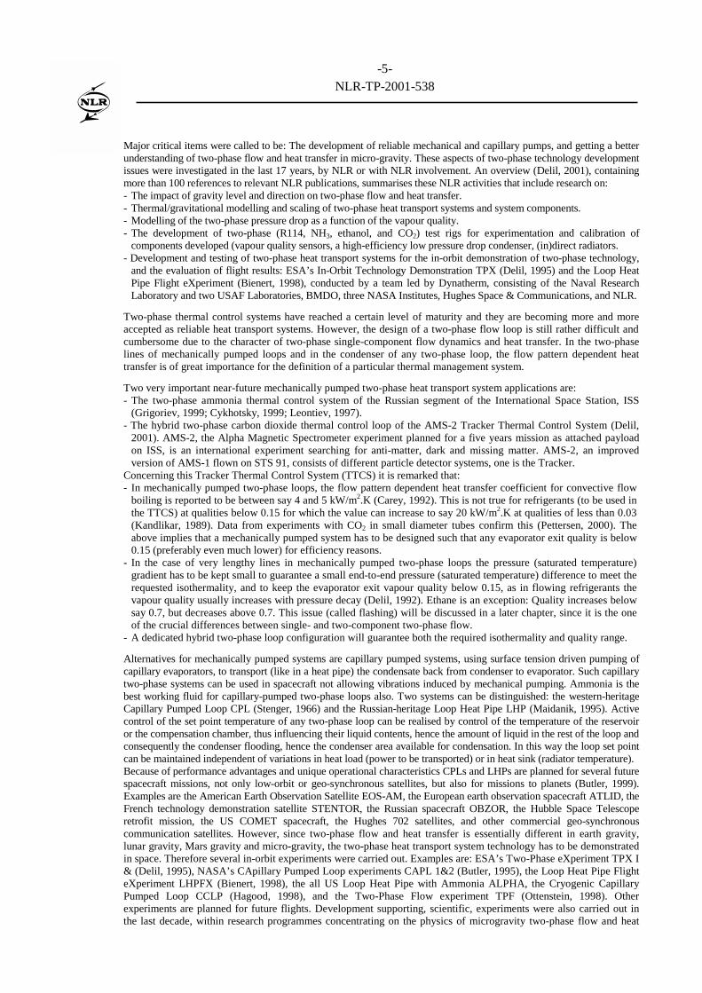
An extra, major, complication is the spatial distribution of liquidand vapour, the so-called flow pattern. Figure 3 schematicallyshows the various flow patterns and boiling mechanisms for up-flow in a, radially heated, vertical tube evaporator: The enteringpure liquid gradually changes to the exiting pure vapour flow, viathe main (morphological) patterns for bubbly, slug, annular and
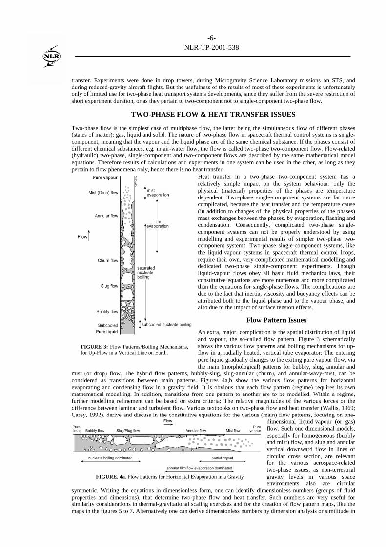
mist (or drop) flow. The hybrid flow patterns, bubbly-slug, slug-annular (churn), and annular-wavy-mist, can beconsidered as transitions between main patterns. Figures 4a,b show the various flow patterns for horizontalevaporating and condensing flow in a gravity field. It is obvious that each flow pattern (regime) requires its ownmathematical modelling. In addition, transitions from one pattern to another are to be modelled. Within a regime,further modelling refinement can be based on extra criteria: The relative magnitudes of the various forces or thedifference between laminar and turbulent flow. Various textbooks on two-phase flow and heat transfer (Wallis, 1969;Carey, 1992), derive and discuss in the constitutive equations for the various (main) flow patterns, focusing on one-
dimensional liquid-vapour (or gas)flow. Such one-dimensional models,especially for homogeneous (bubblyand mist) flow, and slug and annularvertical downward flow in lines ofcircular cross section, are relevantfor the various aerospace-relatedtwo-phase issues, as non-terrestrialgravity levels in various spaceenvironments also are circular
symmetric. Writing the equations in dimensionless form, one can identify dimensionless numbers (groups of fluidproperties and dimensions), that determine two-phase flow and heat transfer. Such numbers are very useful forsimilarity considerations in thermal-gravitational scaling exercises and for the creation of flow pattern maps, like themaps in the figures 5 to 7. Alternatively one can derive dimensionless numbers by dimension analysis or similitude in
FIGURE 3: Flow Patterns/Boiling Mechanisms,for Up-Flow in a Vertical Line on Earth.
FIGURE. 4a. Flow Patterns for Horizontal Evaporation in a Gravity
-7-NLR-TP-2001-538
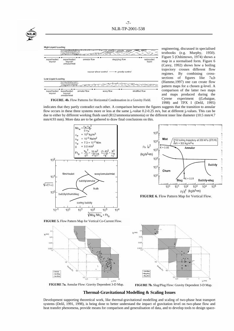
engineering, discussed in specialisedtextbooks (e.g. Murphy, 1950).Figure 5 (Oshimowo, 1974) shows amap in a normalised form. Figure 6(Carey, 1992) shows how a boilingtrajectory crosses different flowregimes. By combining cross-sections of figures like 7a,b(Hamme,1997) one can create flowpattern maps for a chosen g-level. Acomparison of the latter two mapsand maps produced during theCyrene experiment ((Lebaigue,1998) and TPX I (Delil, 1995)
indicates that they partly contradict each other. A comparison between the figures suggests that the transition to annularflow occurs in these three systems more or less at the same jv-value 0.2-0.25 m/s, but at different jl-values. This can bedue to either by different working fluids used (R12/ammonia/ammonia) or the different inner line diameter (10.5 mm/4.7mm/4.93 mm). More data are to be gathered to draw final conclusions on this.
Thermal-Gravitational Modelling & Scaling Issues
Development supporting theoretical work, like thermal-gravitational modelling and scaling of two-phase heat transportsystems (Delil, 1991, 1998), is being done to better understand the impact of gravitation level on two-phase flow andheat transfer phenomena, provide means for comparison and generalisation of data, and to develop tools to design space-
FIGURE 7a. Annular Flow: Gravity Dependent 3-D Map. FIGURE 7b. Slug/Plug Flow: Gravity Dependent 3-D Map.
FIGURE. 4b. Flow Patterns for Horizontal Condensation in a Gravity Field.
FIGURE 6. Flow Pattern Map for Vertical Flow.
FIGURE 5. Flow Pattern Map for Vertical Co-Current Flow.
-8-NLR-TP-2001-538
oriented two-phase loops (components), based on terrestrial tests, to reduce costs. The main goal of the scaling of space-related two-phase heat transport systems is to develop reliable spacecraft systems, whose reduced gravity performancecan be predicted using results of experiments with scale models on earth. Scaling spacecraft systems proved to be usefulalso for in-orbit technology demonstration (e.g. the performance of spacecraft heat transport systems can be predictedbased on the outcomes of in-orbit experiments on model systems with reduced geometry or different working fluid), andto define in-orbit experiments to isolate phenomena to be investigated, (e.g. excluding gravity-induced disturbingbuoyancy effects on alloy melting, diffusion and crystal growth), for a better understanding of the phenomena. Themagnitude of the gravitational scaling varies with the objectives from 1 g to 10-6 g, to reduced g (0.16 g for Moon base,0.4 g for Mars base systems), and to super-g values, pertaining to larger planets or rotating spacecraft.
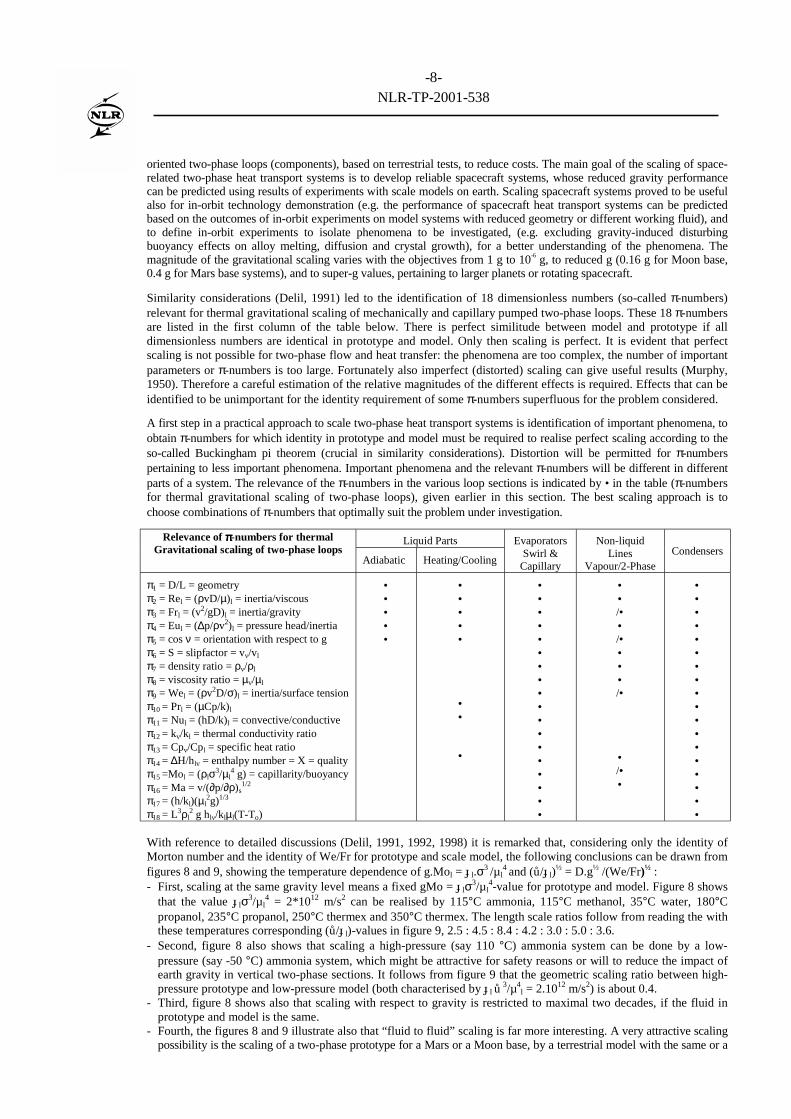
Similarity considerations (Delil, 1991) led to the identification of 18 dimensionless numbers (so-called π-numbers)relevant for thermal gravitational scaling of mechanically and capillary pumped two-phase loops. These 18 π-numbersare listed in the first column of the table below. There is perfect similitude between model and prototype if alldimensionless numbers are identical in prototype and model. Only then scaling is perfect. It is evident that perfectscaling is not possible for two-phase flow and heat transfer: the phenomena are too complex, the number of importantparameters or π-numbers is too large. Fortunately also imperfect (distorted) scaling can give useful results (Murphy,1950). Therefore a careful estimation of the relative magnitudes of the different effects is required. Effects that can beidentified to be unimportant for the identity requirement of some π-numbers superfluous for the problem considered.
A first step in a practical approach to scale two-phase heat transport systems is identification of important phenomena, toobtain π-numbers for which identity in prototype and model must be required to realise perfect scaling according to theso-called Buckingham pi theorem (crucial in similarity considerations). Distortion will be permitted for π-numberspertaining to less important phenomena. Important phenomena and the relevant π-numbers will be different in differentparts of a system. The relevance of the π-numbers in the various loop sections is indicated by • in the table (π-numbersfor thermal gravitational scaling of two-phase loops), given earlier in this section. The best scaling approach is tochoose combinations of π-numbers that optimally suit the problem under investigation.
Liquid PartsRelevance of ππππ-numbers for thermalGravitational scaling of two-phase loops
Adiabatic Heating/Cooling
EvaporatorsSwirl &
Capillary
Non-liquidLines
Vapour/2-PhaseCondensers
π1 = D/L = geometryπ2 = Rel = (ρvD/µ)l = inertia/viscousπ3 = Frl = (v2/gD)l = inertia/gravityπ4 = Eul = (∆p/ρv2)l = pressure head/inertiaπ5 = cos ν = orientation with respect to gπ6 = S = slipfactor = vv/vl
π7 = density ratio = ρv/ρl
π8 = viscosity ratio = µv/µl
π9 = Wel = (ρv2D/σ)l = inertia/surface tensionπ10 = Prl = (µCp/k)l
π11 = Nul = (hD/k)l = convective/conductiveπ12 = kv/kl = thermal conductivity ratioπ13 = Cpv/Cpl = specific heat ratioπ14 = ∆H/hlv = enthalpy number = X = qualityπ15 =Mol = (ρlσ3/µl
4 g) = capillarity/buoyancyπ16 = Ma = v/(∂p/∂ρ)s
1/2
π17 = (h/kl)(µl2g)1/3
π18 = L3ρl2 g hlv/klµl(T-To)
•••••
•••••
••
•
••••••••••••••••••
••/••/••••/•
•/••
••••••••••••••••••
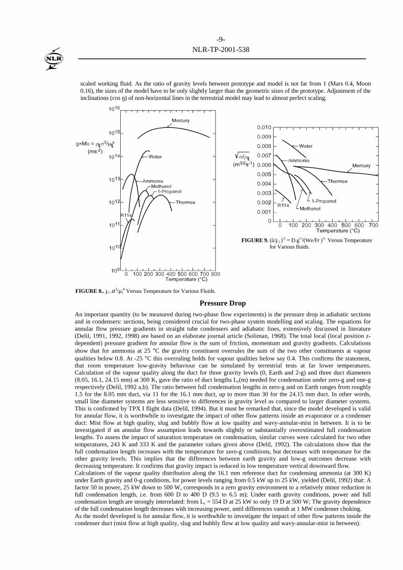
With reference to detailed discussions (Delil, 1991, 1992, 1998) it is remarked that, considering only the identity ofMorton number and the identity of We/Fr for prototype and scale model, the following conclusions can be drawn fromfigures 8 and 9, showing the temperature dependence of g.Mol = ɟl.σ3 /µl
4 and (ů/ɟl)½ = D.g½ /(We/Fr)½ :
- First, scaling at the same gravity level means a fixed gMo = ɟlσ3/µl4-value for prototype and model. Figure 8 shows
that the value ɟlσ3/µl4 = 2*1012 m/s2 can be realised by 115°C ammonia, 115°C methanol, 35°C water, 180°C
propanol, 235°C propanol, 250°C thermex and 350°C thermex. The length scale ratios follow from reading the withthese temperatures corresponding (ů/ɟl)-values in figure 9, 2.5 : 4.5 : 8.4 : 4.2 : 3.0 : 5.0 : 3.6.
- Second, figure 8 also shows that scaling a high-pressure (say 110 °C) ammonia system can be done by a low-pressure (say -50 °C) ammonia system, which might be attractive for safety reasons or will to reduce the impact ofearth gravity in vertical two-phase sections. It follows from figure 9 that the geometric scaling ratio between high-pressure prototype and low-pressure model (both characterised by ɟl
ů 3/µ4l = 2.1012 m/s2) is about 0.4.
- Third, figure 8 shows also that scaling with respect to gravity is restricted to maximal two decades, if the fluid inprototype and model is the same.
- Fourth, the figures 8 and 9 illustrate also that “fluid to fluid” scaling is far more interesting. A very attractive scalingpossibility is the scaling of a two-phase prototype for a Mars or a Moon base, by a terrestrial model with the same or a
-9-NLR-TP-2001-538
scaled working fluid. As the ratio of gravity levels between prototype and model is not far from 1 (Mars 0.4, Moon0.16), the sizes of the model have to be only slightly larger than the geometric sizes of the prototype. Adjustment of theinclinations (cos ɡ) of non-horizontal lines in the terrestrial model may lead to almost perfect scaling.
Pressure Drop
An important quantity (to be measured during two-phase flow experiments) is the pressure drop in adiabatic sectionsand in condensers: sections, being considered crucial for two-phase system modelling and scaling. The equations forannular flow pressure gradients in straight tube condensers and adiabatic lines, extensively discussed in literature(Delil, 1991, 1992, 1998) are based on an elaborate journal article (Soliman, 1968). The total local (local position z-dependent) pressure gradient for annular flow is the sum of friction, momentum and gravity gradients. Calculationsshow that for ammonia at 25 °C the gravity constituent overrules the sum of the two other constituents at vapourqualities below 0.8. At -25 °C this overruling holds for vapour qualities below say 0.4. This confirms the statement,that room temperature low-gravity behaviour can be simulated by terrestrial tests at far lower temperatures.Calculation of the vapour quality along the duct for three gravity levels (0, Earth and 2-g) and three duct diameters(8.05, 16.1, 24.15 mm) at 300 K, gave the ratio of duct lengths Lc(m) needed for condensation under zero-g and one-grespectively (Delil, 1992 a,b). The ratio between full condensation lengths in zero-g and on Earth ranges from roughly1.5 for the 8.05 mm duct, via 11 for the 16.1 mm duct, up to more than 30 for the 24.15 mm duct. In other words,small line diameter systems are less sensitive to differences in gravity level as compared to larger diameter systems.This is confirmed by TPX I flight data (Delil, 1994). But it must be remarked that, since the model developed is validfor annular flow, it is worthwhile to investigate the impact of other flow patterns inside an evaporator or a condenserduct: Mist flow at high quality, slug and bubbly flow at low quality and wavy-annular-mist in between. It is to beinvestigated if an annular flow assumption leads towards slightly or substantially overestimated full condensationlengths. To assess the impact of saturation temperature on condensation, similar curves were calculated for two othertemperatures, 243 K and 333 K and the parameter values given above (Delil, 1992). The calculations show that thefull condensation length increases with the temperature for zero-g conditions, but decreases with temperature for theother gravity levels. This implies that the differences between earth gravity and low-g outcomes decrease withdecreasing temperature. It confirms that gravity impact is reduced in low temperature vertical downward flow.Calculations of the vapour quality distribution along the 16.1 mm reference duct for condensing ammonia (at 300 K)under Earth gravity and 0-g conditions, for power levels ranging from 0.5 kW up to 25 kW, yielded (Delil, 1992) that: Afactor 50 in power, 25 kW down to 500 W, corresponds in a zero gravity environment to a relatively minor reduction infull condensation length, i.e. from 600 D to 400 D (9.5 to 6.5 m); Under earth gravity conditions, power and fullcondensation length are strongly interrelated: from Lc = 554 D at 25 kW to only 19 D at 500 W; The gravity dependenceof the full condensation length decreases with increasing power, until differences vanish at 1 MW condenser choking.As the model developed is for annular flow, it is worthwhile to investigate the impact of other flow patterns inside thecondenser duct (mist flow at high quality, slug and bubbly flow at low quality and wavy-annular-mist in between).
FIGURE 8.. ɟl .σ3/µl4 Versus Temperature for Various Fluids.
FIGURE 9. (ů/ɟl )½ = D.g½/(We/Fr )½ Versus Temperature
for Various fluids.
-10-NLR-TP-2001-538
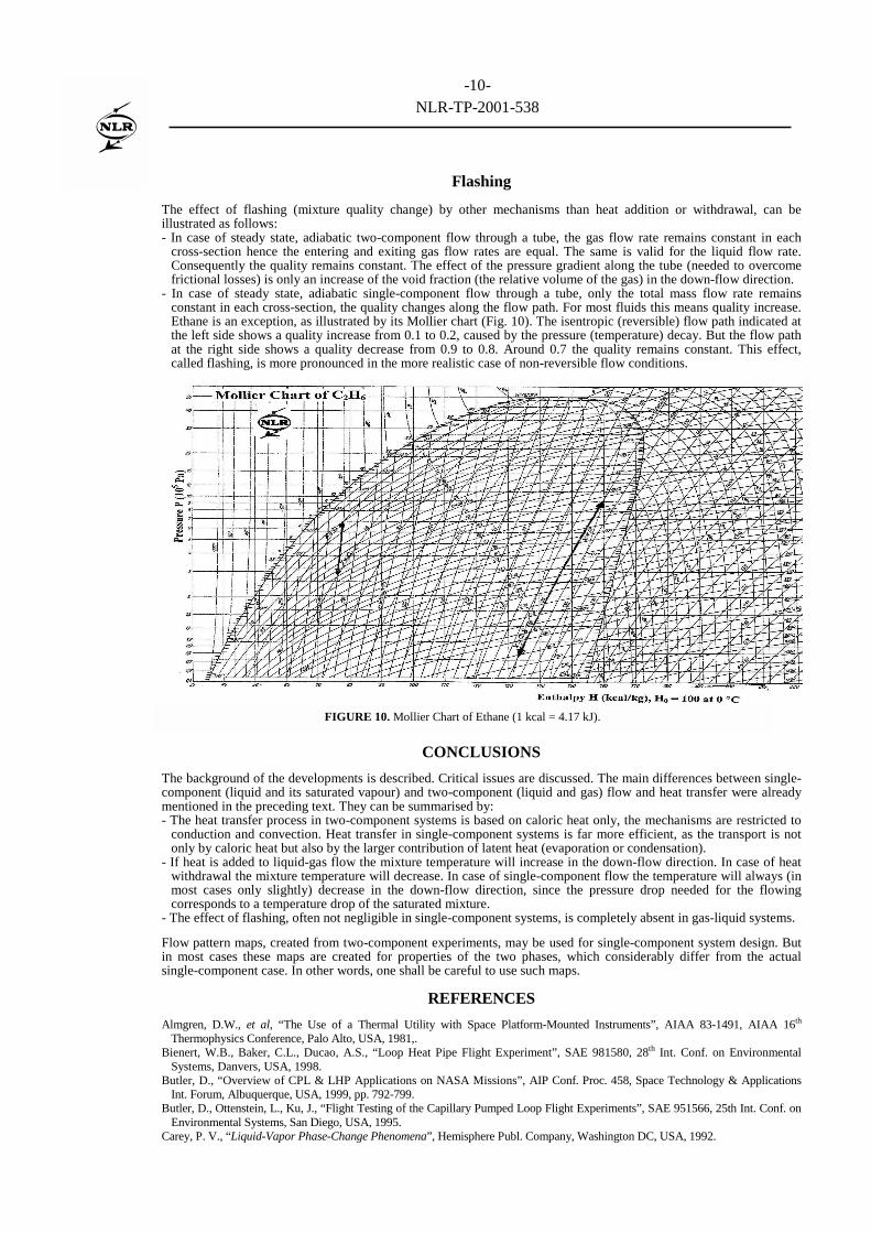
Flashing
The effect of flashing (mixture quality change) by other mechanisms than heat addition or withdrawal, can beillustrated as follows:- In case of steady state, adiabatic two-component flow through a tube, the gas flow rate remains constant in each
cross-section hence the entering and exiting gas flow rates are equal. The same is valid for the liquid flow rate.Consequently the quality remains constant. The effect of the pressure gradient along the tube (needed to overcomefrictional losses) is only an increase of the void fraction (the relative volume of the gas) in the down-flow direction.
- In case of steady state, adiabatic single-component flow through a tube, only the total mass flow rate remainsconstant in each cross-section, the quality changes along the flow path. For most fluids this means quality increase.Ethane is an exception, as illustrated by its Mollier chart (Fig. 10). The isentropic (reversible) flow path indicated atthe left side shows a quality increase from 0.1 to 0.2, caused by the pressure (temperature) decay. But the flow pathat the right side shows a quality decrease from 0.9 to 0.8. Around 0.7 the quality remains constant. This effect,called flashing, is more pronounced in the more realistic case of non-reversible flow conditions.
CONCLUSIONS
The background of the developments is described. Critical issues are discussed. The main differences between single-component (liquid and its saturated vapour) and two-component (liquid and gas) flow and heat transfer were alreadymentioned in the preceding text. They can be summarised by:- The heat transfer process in two-component systems is based on caloric heat only, the mechanisms are restricted to
conduction and convection. Heat transfer in single-component systems is far more efficient, as the transport is notonly by caloric heat but also by the larger contribution of latent heat (evaporation or condensation).
- If heat is added to liquid-gas flow the mixture temperature will increase in the down-flow direction. In case of heatwithdrawal the mixture temperature will decrease. In case of single-component flow the temperature will always (inmost cases only slightly) decrease in the down-flow direction, since the pressure drop needed for the flowingcorresponds to a temperature drop of the saturated mixture.
- The effect of flashing, often not negligible in single-component systems, is completely absent in gas-liquid systems.
Flow pattern maps, created from two-component experiments, may be used for single-component system design. Butin most cases these maps are created for properties of the two phases, which considerably differ from the actualsingle-component case. In other words, one shall be careful to use such maps.
REFERENCES
Almgren, D.W., et al, “The Use of a Thermal Utility with Space Platform-Mounted Instruments”, AIAA 83-1491, AIAA 16th
Thermophysics Conference, Palo Alto, USA, 1981,.Bienert, W.B., Baker, C.L., Ducao, A.S., “Loop Heat Pipe Flight Experiment”, SAE 981580, 28th Int. Conf. on Environmental
Systems, Danvers, USA, 1998.Butler, D., “Overview of CPL & LHP Applications on NASA Missions”, AIP Conf. Proc. 458, Space Technology & Applications
Int. Forum, Albuquerque, USA, 1999, pp. 792-799.Butler, D., Ottenstein, L., Ku, J., “Flight Testing of the Capillary Pumped Loop Flight Experiments”, SAE 951566, 25th Int. Conf. on
Environmental Systems, San Diego, USA, 1995.Carey, P. V., “Liquid-Vapor Phase-Change Phenomena”, Hemisphere Publ. Company, Washington DC, USA, 1992.
FIGURE 10. Mollier Chart of Ethane (1 kcal = 4.17 kJ).
-11-NLR-TP-2001-538
Chen, I. et al, “Measurements and Correlation of Two-Phase Pressure Drop under Microgravity Conditions”, J. of Thermophysics,5,1991, pp. 514-523.
Cykhotsky, V.M., et al., “Development and Analyses of Control Methods of the International Space Station Alpha Russian SegmentThermal Control System Parameters”, in Space Technology & Applications Int. Forum (STAIF-1999), edited by M. El-Genk, AIPConf. Proc. 458, New York, USA, 1999, pp. 848-853.
Delil, A.A.M., “Some considerations concerning two-phase flow thermal bus systems for spacecraft”, NLR-RL-84-028, 1984.Delil, A.A.M., “Thermal Gravitational Modelling and Scaling of Two-Phase Heat Transport Systems: Similarity Considerations and
Useful Equations, Predictions Versus Experimental Results”, NLR TP 91477 U, ESA SP-353, 1st European Symposium on Fluids inSpace, Ajaccio, France, 1991, pp. 579-599.
Delil, A.A.M., “Gravity Dependence of Pressure Drop and Heat transfer in Straight Two-Phase Heat Transport System CondenserDucts”, NLR TP 92167 U, SAE 921168, 22nd Int. Conf. on Environmental Systems, Seattle, USA, 1992.
Delil, A.A.M., et al., “TPX for In-Orbit Demonstration of Two-Phase Heat Transport Technology - Evaluation of Flight &Postflight Experiment Results”, NLR TP 95192, SAE 95150, 25th Int. Conf. on Environmental Systems, San Diego, USA, 1995.
Delil, A.A.M., “Two-Phase Heat Transport Systems for Space: Thermal Gravitational Modelling & Scaling, SimilarityConsiderations, Equations, Predictions, Experimental Data and Flow Pattern Mapping”, NLR TP 98268, SAE 981692, 28th Int.Conf. on Environmental Systems, Danvers, USA, 1998.
Delil, A.A.M., “Aerospace-Related Fluid Physics, Heat Transfer, and Thermal Control Research at the NLR Space Division”,NLR-TP-2001, Proc. HEFAT 2002, 1st Int. Conf. on Heat Transfer, Fluid Mechanics and Thermodynamics, 8-10 April 2002,Kruger Park, South Africa.
Grigoriev, Y.I., et al., “Two-Phase Thermal Control System of International Space Station Alpha Russian Segment”, Proc. Int.Workshop Non- Compression Refrigeration & Cooling”, Odessa, Ukraine, 1999, pp.73-83.
Hagood, R., “CCPL Flight Experiment: Concepts through Integration”, SAE 981694, 28th Int. Conf. on Environmental Systems,Danvers, USA, 1998.
Hamme, T.A., Best, F.R., “ Gravity Dependent Flow Regime Mapping”, Space Technology & Applications Int. Forum (STAIF-1997),edited by M. El-Genk, ”, AIP Conf. Proc. 387, New York, USA, 1997, pp. 635-640.
Haslett, B., “Space Station Technology 1983, Thermal Control”, NASA CP-2293, 1983, pp. 165-185.Kandlikar, S.G., “A general correlation for saturated two-phase flow boiling heat transfer inside horizontal and vertical tubes”, J. Heat
Transfer, 112, 1989, pp. 219-228.Lebaigue, O., Bouzou, N., Colin, C., “Cyrène: An Experimental Two-Phase Ammonia Fluid Loop in Microgravity. Results of a
Parabolic Flight Campaign”, SAE 981689, 28th Int. Conf. on Environmental Systems, Danvers, USA, 1998.Leontiev, A.I., et al.,”Thermophysics of Two-Phase Flows in Microgravity: Russian-American Research Project, Space Technology &
Applications Int. Forum (STAIF-1997), edited by M. El-Genk, ”, AIP Conf. Proc. 387, New York, USA, 1997, pp. 541-546.Maidanik, Y.F., Solodovnik, N., Fershtater, Y.G., “Investigation of Dynamic and Stationary Characteristics of Loop Heat Pipe”, Proc.
9th Int. Heat Pipe Conf. Albuquerque, USA, 1995, pp. 1000-1006.Murphy, G., “Similitude in Engineering”, Ronald Press, New York, USA, 1950.Oren, J.A., “Study of Thermal Management for Space Platform Applications”, NASA CR-165307, 1981.Oshinowo, T., Charles, M.E., “Vertical Two-Phase Flow, Flow Pattern Correlations", Can. J. Chem. Engng., 52, 1974, pp. 25-35.Ottenstein, L., Nienberg, J., “Flight Testing of the Two-Phase Flow Flight Experiment”, SAE 981816, 28th Int. Conf. on
Environmental Systems, Danvers, USA, 1998.Pettersen, J., Rieberer, R., Munkejord, S.T., “Heat Transfer and Pressure Drop for Flow of Supercritical and Subcritical CO2 in
Microchannel Tubes”, Norwegian Univ. of Science and Technology/SINTEF Energy Research TR A5127, 2000.Soliman, M., Schuster, J.R., Berenson, P.J., “A General Heat Transfer Correlation for Annular Flow Condensation“, Trans. ASME, J.
Heat Transfer, 90, 1968, pp. 267-276.Stalmach, D.D., Oren, J.A., “Systems Evaluation of Thermal Bus Concepts”, NASA CR-167774, 1982.Stenger, F.J., “Experimental Study of Water-Filled Capillary Pumped Heat Transfer Loops”, NASA TMX-1310, 1966.
NOMENCLATUREBo boiling number (-)Cp specific heat at constant pressure (J/kg.K)D diameter (m)Eu Euler number (-)Fr Froude number (-)g gravitational acceleration (m/s2)H enthalpy (J/kg)h heat transfer coefficient (W/m2.K)hlv latent heat of vaporisation (J/kg)j superficial velocity (m/s)L length (m)Ma Mach number (-)Mo Morton number (-)Nu Nusselt number (-)p pressure (Pa = N/m2)Pr Prandtl number (-)Q power (W)
Re Reynolds number (-)S slip factor (-)T temperature (K) or (°C = K – 273.15)v velocity (m/s)We Weber number (-)X vapour quality (-)z axial or vertical co-ordinate (m)α vapour fraction (volumetric) (-)∆ difference, drop (-)µ viscosity (N.s/m2)σ surface tension (N/m)ɚ thermal conductivity (W/m.K)π1, etc dimensionless number (-)ρ density (kg/m3)ν angle (with respect to gravity) (rad)
Subscripts: c = condenser l = liquid g = gravitation s = entropy v = vapour tp = two-phase w = water