Embed Size (px)
Citation preview
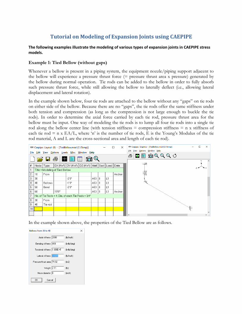
Tutorial on Modeling of Expansion Joints using CAEPIPE
The following examples illustrate the modeling of various types of expansion joints in CAEPIPE stress models.
Example 1: Tied Bellow (without gaps)
Whenever a bellow is present in a piping system, the equipment nozzle/piping support adjacent to the bellow will experience a pressure thrust force (= pressure thrust area x pressure) generated by the bellow during normal operation. Tie rods can be added to the bellow in order to fully absorb such pressure thrust force, while still allowing the bellow to laterally deflect (i.e., allowing lateral displacement and lateral rotation).
In the example shown below, four tie rods are attached to the bellow without any “gaps” on tie rods on either side of the bellow. Because there are no “gaps”, the tie rods offer the same stiffness under both tension and compression (as long as the compression is not large enough to buckle the tie rods). In order to determine the axial force carried by each tie rod, pressure thrust area for the bellow must be input. One way of modeling the tie rods is to lump all four tie rods into a single tie rod along the bellow center line (with tension stiffness = compression stiffness = n x stiffness of each tie rod = n x EA/L, where ‘n’ is the number of tie rods, E is the Young’s Modulus of the tie rod material, A and L are the cross-sectional area and length of each tie rod).
In the example shown above, the properties of the Tied Bellow are as follows.
Note:
For Bending stiffness of the bellow, the following two options are provided.
Option 1: Input the Bending stiffness as specified by the manufacturer or as reasonably determined from industry standards such as EJMA. If a non-zero value for Bending stiffness is input, then leave the “Mean diameter” field blank.
Option 2: If a non-zero value for Bending stiffness is not input as per Option 1 above and is left blank, then input the actual non-zero value for “Mean diameter”, in which case CAEPIPE will internally calculate the Bending stiffness for the bellow based on the Mean diameter and other inputs provided for that bellow. In this case, the Mean diameter is the “mean” between the outer and inner diameters of any Convolution of the bellow. Since outer and inner diameters of all convolutions of the bellow are the same, the Mean diameter is the same for all convolutions of that bellow.
Among the above two options, Option 1 is recommended if you are able to specify a realistic non-zero value for the Bending stiffness of the bellow.
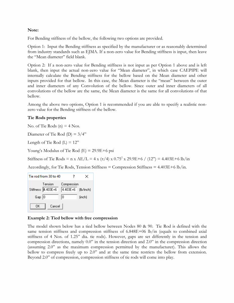
Tie Rods properties
No. of Tie Rods (n) = 4 Nos.
Diameter of Tie Rod (D) = 3/4”
Length of Tie Rod (L) = 12”
Young’s Modulus of Tie Rod (E) = 29.9E+6 psi
Stiffness of Tie Rods = n x AE/L = 4 x (π/4) x 0.752 x 29.9E+6 / (12”) = 4.403E+6 lb/in
Accordingly, for Tie Rods, Tension Stiffness = Compression Stiffness = 4.403E+6 lb/in.
Example 2: Tied bellow with free compression
The model shown below has a tied bellow between Nodes 80 & 90. Tie Rod is defined with the same tension stiffness and compression stiffness of 6.848E+06 lb/in (equals to combined axial stiffness of 4 Nos. of 1.25” dia. tie rods). However, gaps are set differently in the tension and compression directions, namely 0.0” in the tension direction and 2.0” in the compression direction (assuming 2.0” as the maximum compression permitted by the manufacturer). This allows the bellow to compress freely up to 2.0” and at the same time restricts the bellow from extension. Beyond 2.0” of compression, compression stiffness of tie rods will come into play.
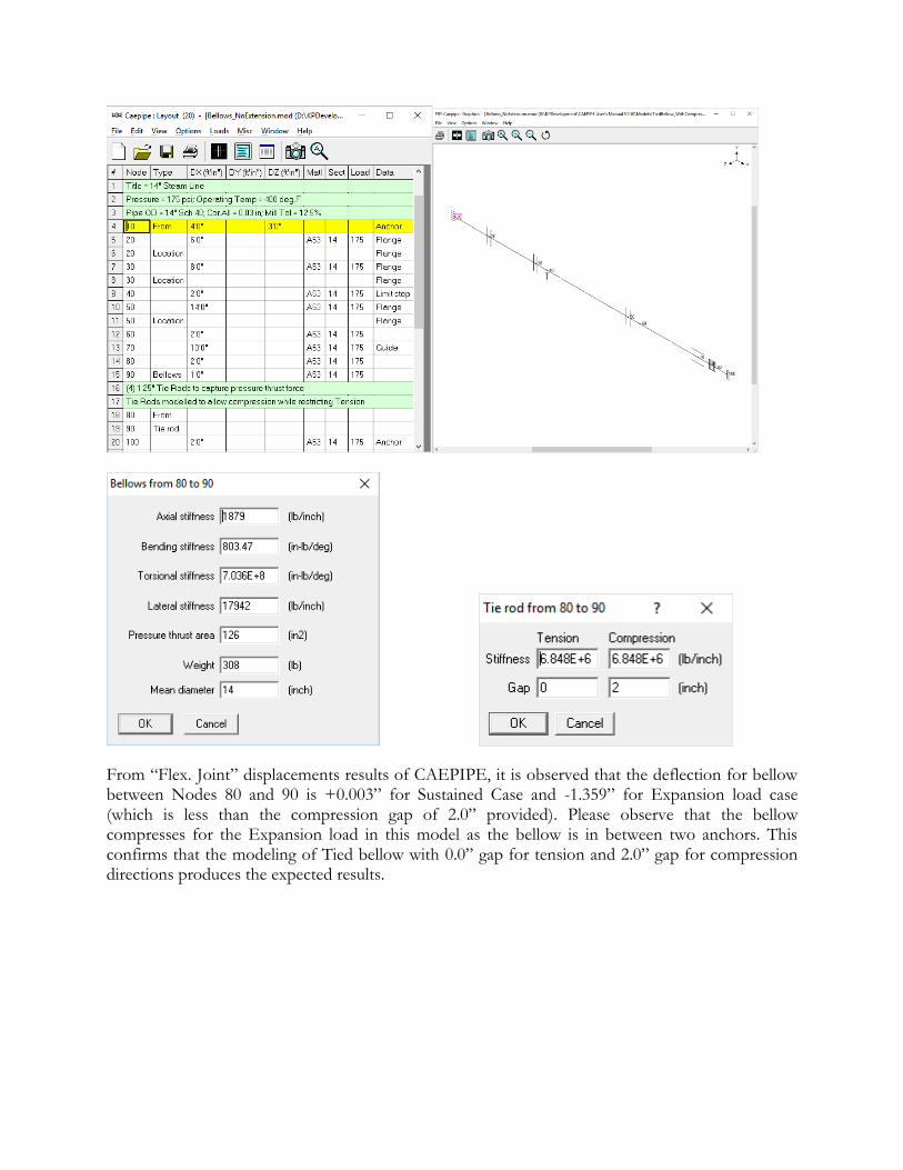
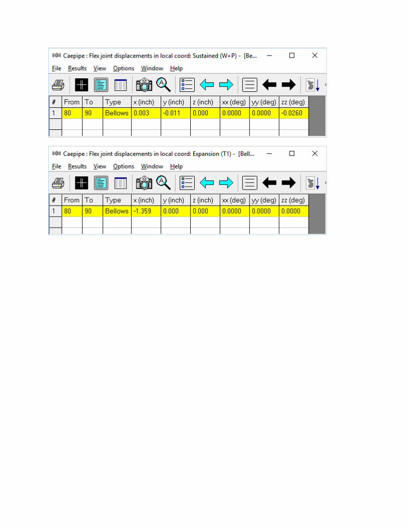
From “Flex. Joint” displacements results of CAEPIPE, it is observed that the deflection for bellow between Nodes 80 and 90 is +0.003” for Sustained Case and -1.359” for Expansion load case (which is less than the compression gap of 2.0” provided). Please observe that the bellow compresses for the Expansion load in this model as the bellow is in between two anchors. This confirms that the modeling of Tied bellow with 0.0” gap for tension and 2.0” gap for compression directions produces the expected results.
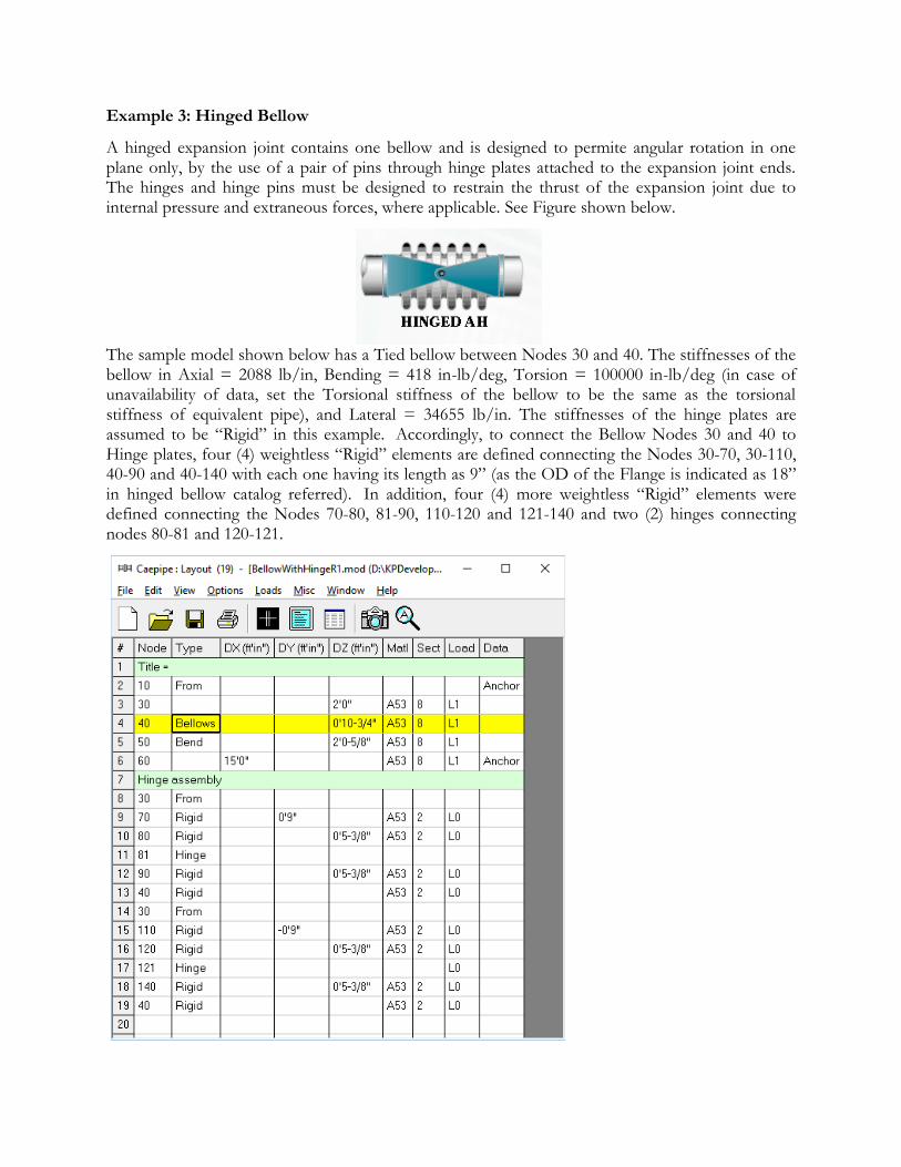
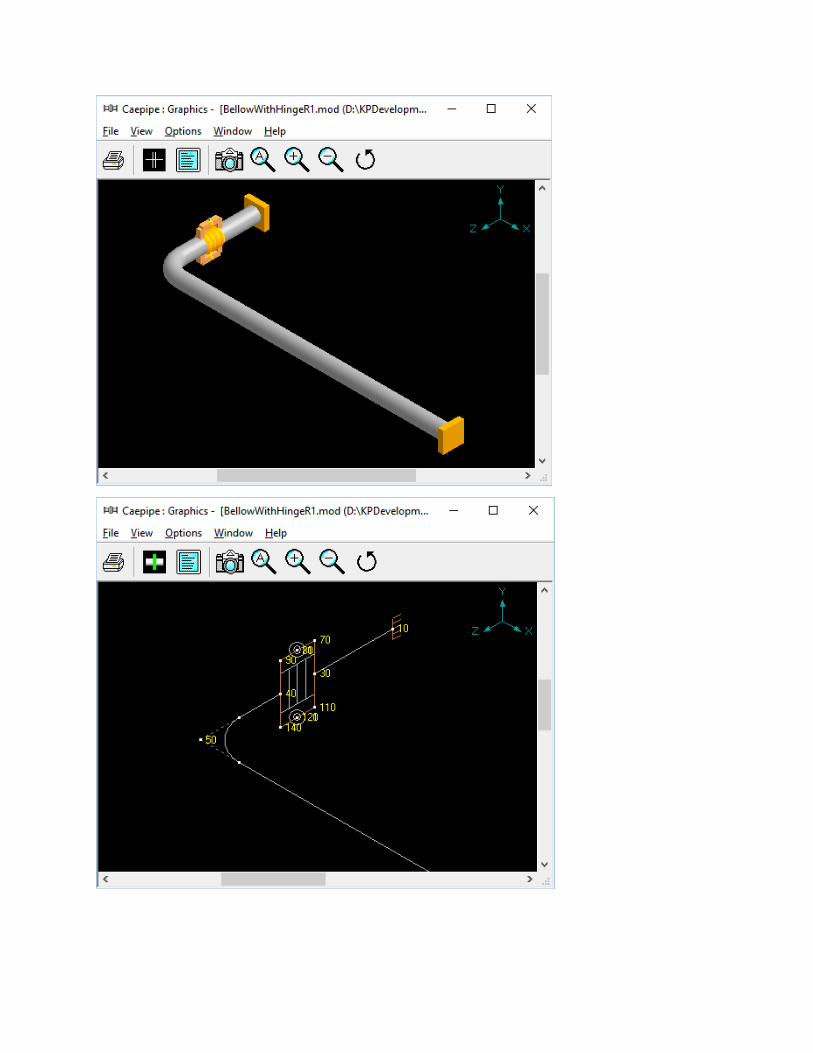
Example 3: Hinged Bellow
A hinged expansion joint contains one bellow and is designed to permite angular rotation in one plane only, by the use of a pair of pins through hinge plates attached to the expansion joint ends. The hinges and hinge pins must be designed to restrain the thrust of the expansion joint due to internal pressure and extraneous forces, where applicable. See Figure shown below.
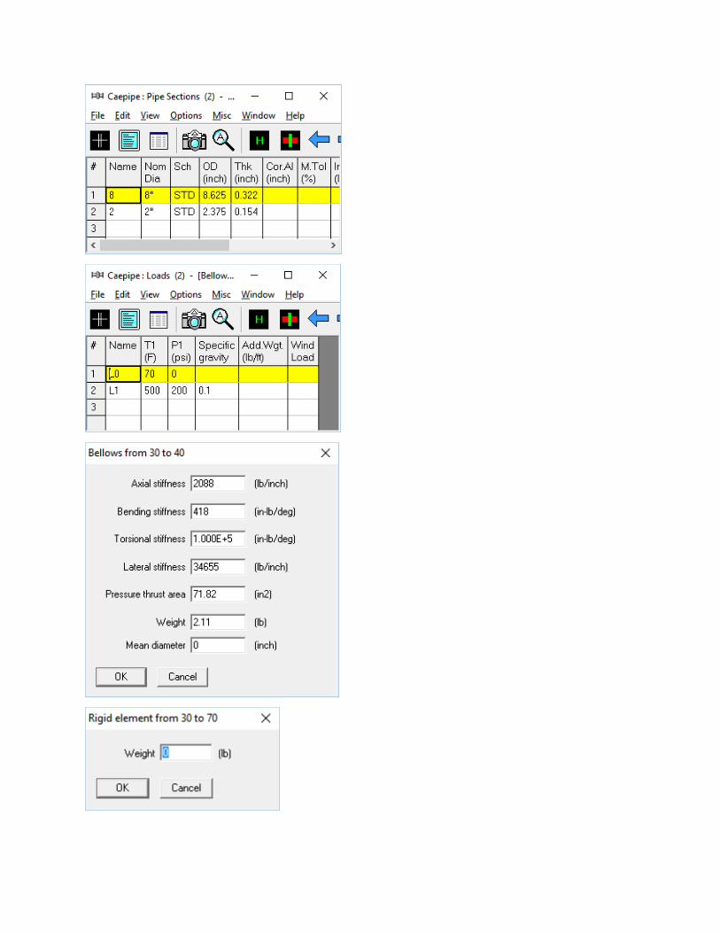
The sample model shown below has a Tied bellow between Nodes 30 and 40. The stiffnesses of the bellow in Axial = 2088 lb/in, Bending = 418 in-lb/deg, Torsion = 100000 in-lb/deg (in case of unavailability of data, set the Torsional stiffness of the bellow to be the same as the torsional stiffness of equivalent pipe), and Lateral = 34655 lb/in. The stiffnesses of the hinge plates are assumed to be “Rigid” in this example. Accordingly, to connect the Bellow Nodes 30 and 40 to Hinge plates, four (4) weightless “Rigid” elements are defined connecting the Nodes 30-70, 30-110, 40-90 and 40-140 with each one having its length as 9” (as the OD of the Flange is indicated as 18” in hinged bellow catalog referred). In addition, four (4) more weightless “Rigid” elements were defined connecting the Nodes 70-80, 81-90, 110-120 and 121-140 and two (2) hinges connecting nodes 80-81 and 120-121.
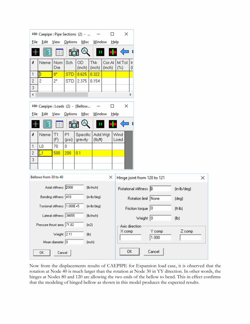
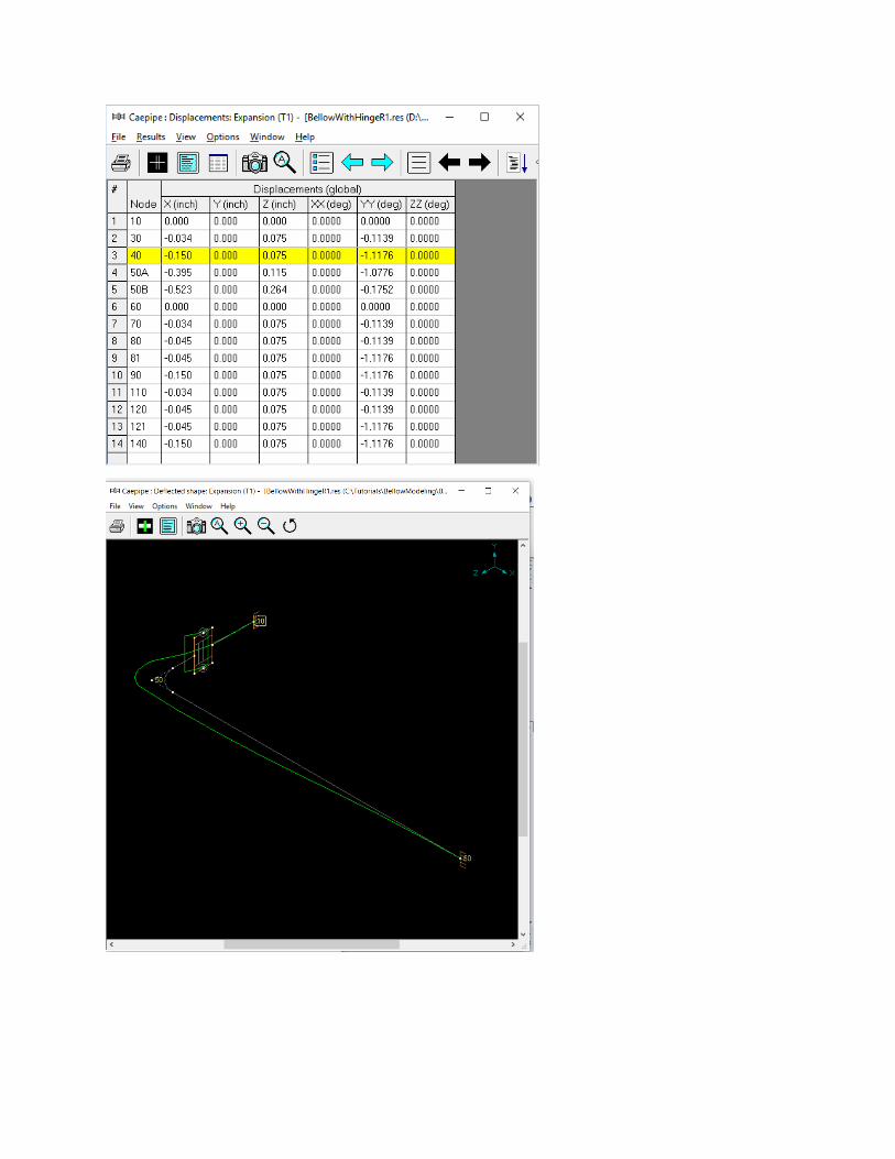
Now from the displacements results of CAEPIPE for Expansion load case, it is observed that the rotation at Node 40 is much larger than the rotation at Node 30 in YY direction. In other words, the hinges at Nodes 80 and 120 are allowing the two ends of the bellow to bend. This in effect confirms that the modeling of hinged bellow as shown in this model produces the expected results.
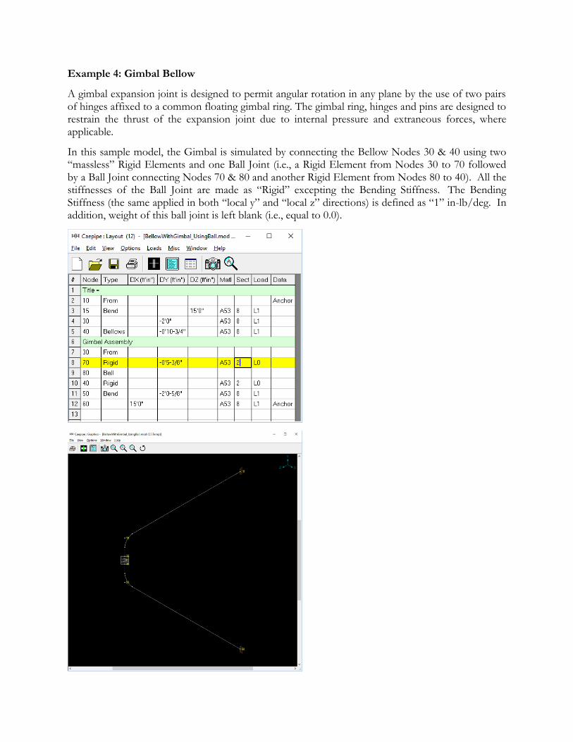
Example 4: Gimbal Bellow
A gimbal expansion joint is designed to permit angular rotation in any plane by the use of two pairs of hinges affixed to a common floating gimbal ring. The gimbal ring, hinges and pins are designed to restrain the thrust of the expansion joint due to internal pressure and extraneous forces, where applicable.
In this sample model, the Gimbal is simulated by connecting the Bellow Nodes 30 & 40 using two “massless” Rigid Elements and one Ball Joint (i.e., a Rigid Element from Nodes 30 to 70 followed by a Ball Joint connecting Nodes 70 & 80 and another Rigid Element from Nodes 80 to 40). All the stiffnesses of the Ball Joint are made as “Rigid” excepting the Bending Stiffness. The Bending Stiffness (the same applied in both “local y” and “local z” directions) is defined as “1” in-lb/deg. In addition, weight of this ball joint is left blank (i.e., equal to 0.0).
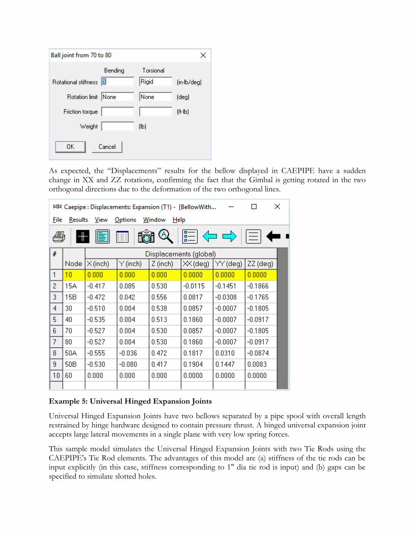
As expected, the “Displacements” results for the bellow displayed in CAEPIPE have a sudden change in XX and ZZ rotations, confirming the fact that the Gimbal is getting rotated in the two orthogonal directions due to the deformation of the two orthogonal lines.
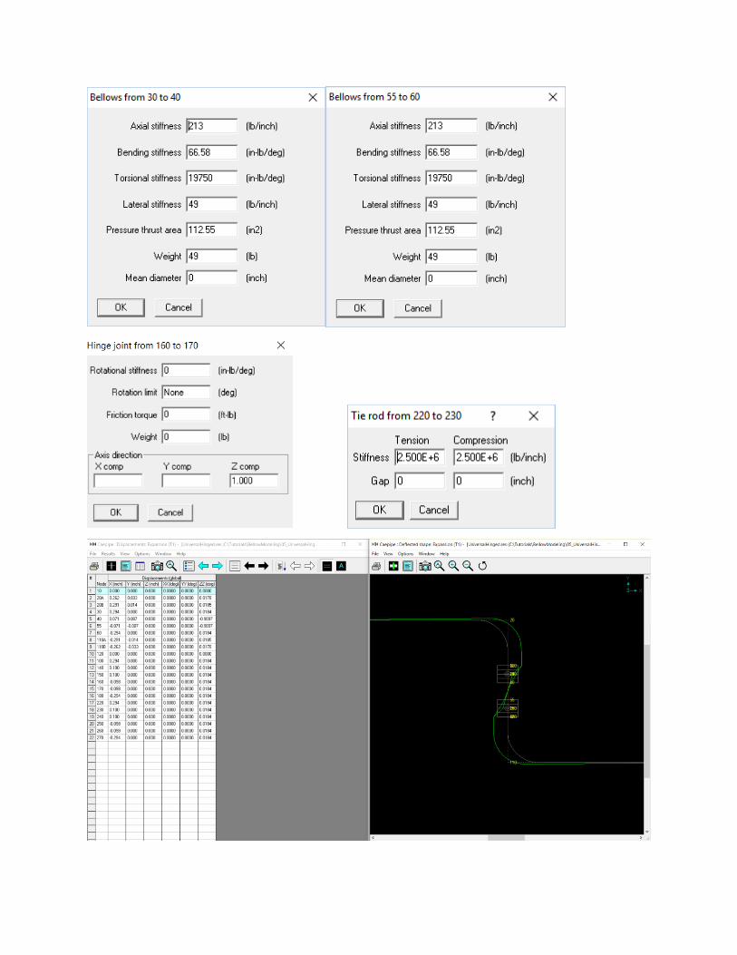
Example 5: Universal Hinged Expansion Joints
Universal Hinged Expansion Joints have two bellows separated by a pipe spool with overall length restrained by hinge hardware designed to contain pressure thrust. A hinged universal expansion joint accepts large lateral movements in a single plane with very low spring forces.
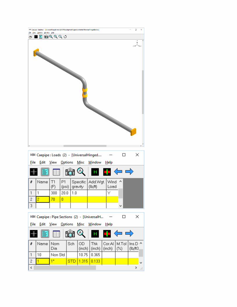
This sample model simulates the Universal Hinged Expansion Joints with two Tie Rods using the CAEPIPE's Tie Rod elements. The advantages of this model are (a) stiffness of the tie rods can be input explicitly (in this case, stiffness corresponding to 1" dia tie rod is input) and (b) gaps can be specified to simulate slotted holes.
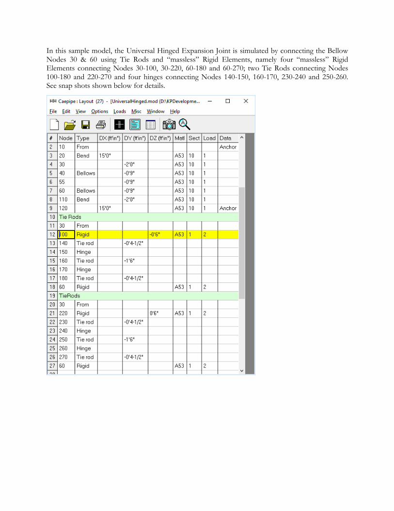
In this sample model, the Universal Hinged Expansion Joint is simulated by connecting the Bellow Nodes 30 & 60 using Tie Rods and “massless” Rigid Elements, namely four “massless” Rigid Elements connecting Nodes 30-100, 30-220, 60-180 and 60-270; two Tie Rods connecting Nodes 100-180 and 220-270 and four hinges connecting Nodes 140-150, 160-170, 230-240 and 250-260. See snap shots shown below for details.
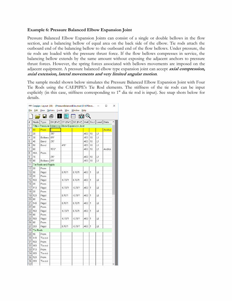
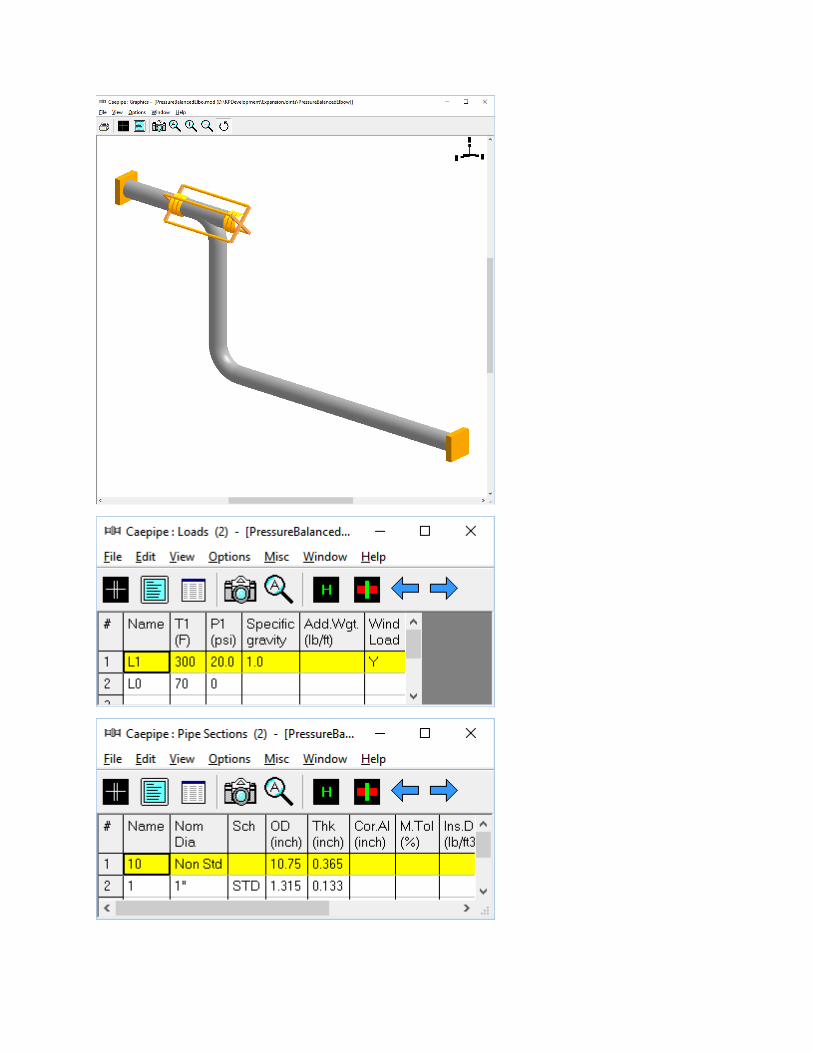
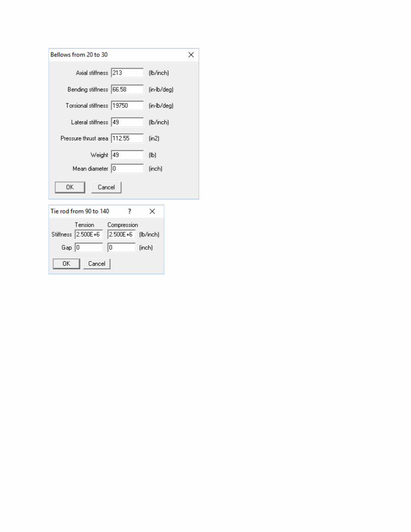
Example 6: Pressure Balanced Elbow Expansion Joint
Pressure Balanced Elbow Expansion Joints can consist of a single or double bellows in the flow section, and a balancing bellow of equal area on the back side of the elbow. Tie rods attach the outboard end of the balancing bellow to the outboard end of the flow bellows. Under pressure, the tie rods are loaded with the pressure thrust force. If the flow bellows compresses in service, the balancing bellow extends by the same amount without exposing the adjacent anchors to pressure thrust forces. However, the spring forces associated with bellows movements are imposed on the adjacent equipment. A pressure balanced elbow type expansion joint can accept axial compression, axial extension, lateral movements and very limited angular motion.
The sample model shown below simulates the Pressure Balanced Elbow Expansion Joint with Four Tie Rods using the CAEPIPE's Tie Rod elements. The stiffness of the tie rods can be input explicitly (in this case, stiffness corresponding to 1" dia tie rod is input). See snap shots below for details.