Embed Size (px)
Citation preview
Tutorial on High Impedance Fault Detection
JC (Jacobus) Theron Technical Applications Engineer GE Energy Connections 650 Markland Street Canada [email protected]
Amit Pal Customer Application Engineering Manager GE Energy Connections Chennai India [email protected]
Abraham Varghese Global Utility Applications Leader GE Energy Connections Stafford, United Kingdom [email protected]
Abstract – High impedance faults are generally not detected by conventional protection functions like over
current, ground fault, distance, differential etc. because of the magnitude of impedance involved in the fault path and the nature and characteristic of the fault current are special and different than the conventional fault current profiles. Each type of high impedance fault is unique in terms of magnitude of fault current, nature, characteristic and waveshape. Majority of the high impedance faults are single phase to ground faults but this can involve phase to phase elements as well. Because of the inability of the conventional protection functions to detect high impedance faults especially high impedance phase to ground faults, the electrical conductor remains live under such condition and as can be imagined, poses a huge and significant risk to wild life and more importantly human life. Atmospheric and geographical conditions have a significant role to play in high impedance phase to ground faults since they have a direct impact on the magnitude and characteristic of the fault current. This paper describes different techniques to detect high impedance phase to ground faults and focuses on the proven algorithms that have been implemented in protection relays, had been verified by real site tests and fault inception on live power lines. The paper is broadly organized as a tutorial. The characteristics of high impedance faults and the challenges involved in detecting them are described first. The paper then goes on to detail some of the important techniques in use for high impedance fault detection highlighting their strengths and weaknesses, and some modern approaches proposed to improve the dependability of protection schemes. In particular, a technique combining the fundamental and harmonic analysis of the fault waveform is presented, along with its performance in field trials carried out in co-operation with utilities.
Index Terms — High Impedance Faults (HIFs or HiZ), Harmonics, Downed Conductor, Instantaneous
overcurrent (IOC or 50), time overcurrent (TOC or 51), Sensitive ground/earth fault (SEF or 50SG), Wattmetric Protection
I. INTRODUCTION, DEFINITION AND CAUSES OF HIGH IMPEDANCE FAULTS
High Impedance Faults (HiZ) generally result when an energized primary conductor makes electrical contact with a quasi-insulated object, such as a tree, pole, road surface, sidewalk, sod with very high impedance grounding, or the ground in the case of conductor breaking and falling to the ground. The significance of these faults is they represent a serious public safety hazard as well as a risk of arcing ignition of fires and little to no damage to the power system is in most cases. In all these cases, the current flowing to ground is so low due to significant grounding impedance or possibly no ground contact, that it cannot be detected by conventional protection functions such as fuses, instantaneous overcurrent (50), time overcurrent (51) or sensitive ground overcurrent (50SG). High Impedance Faults can also be multiphase faults, if for example a tree limb contacts two phase conductors. Throughout the utility industry, there has been differences of opinion on how often HiZ occur. Normally, utilities do not keep good records on the number of down conductor instances. It is seldom recorded on trouble reports unless it results in a fuse, breaker operation or since no or little power system damage occurred. While it is likely that only a few percent (5-20%) of all distribution faults are high impedance faults, means exist to detect a high percentage of HiZ.
Conventional wisdom of protection engineers is that the majority of downed conductors are detected by protection relays, however the perception of line crews is that a more significant percentage of downed conductors still remain energized when they arrive on the scene.
Seasonal and extreme weather conditions can have a significant impact on HIZ. HIFs are typically caused by:
2
A. BROKEN CONDUCTOR ON GROUND (DOWNED CONDUCTOR)
A downed conductor occurs when the primary conductor has a physical break from the system. Depending on the position of the break from the pole/ post the broken conductor may fall to the ground (soil, sand, gravels, road surface/ asphalt etc.) or may be freely suspended in air, yet still energized. This can occur either if the conductor breaks and falls to the ground from the source-end or from the load-end. A source-end downed conductor would occur if the downed conductor gets disconnected from the load but remains connected to the source such as position 1 in Fig 1. A load-end downed conductor gets disconnected from the source but remains connected to the load such as position 2 in Fig 1. Typically, downed conductor still connected to the source-end provides enough current for conventional feeder protection elements to operate, however, downed conductors from the load-end would typically have some of the distribution transformer impedance and/or load impedance between relaying point (feeder breaker) and downed conductor with consequently a very small to no fault current very hard to detect.
Fig 1: Source-end and Load-end Downed Conductors
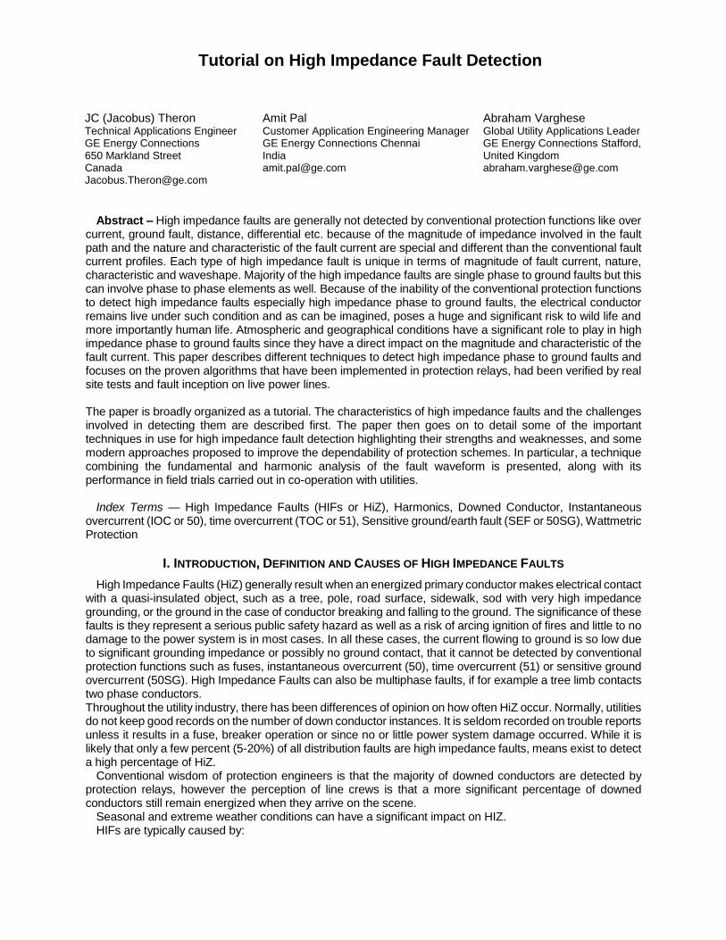
B. BROKEN POLE ALLOWING CONDUCTOR TO GROUND OR CONDUCTING SURFACE CONTACT
This can occur when the feeder structure pole breaks, and causes conductor contact with either ground or other surfaces such as asphalt roads, trees, sod etc.
Fig 2: Broken Poles Downed Conductors
C. BROKEN POLE, TREE LIMB OR ICE ALLOWING CONDUCTOR SAG
This can occur when the feeder structure pole breaks, or a tree falls on the main conductors, and cause them to sag, potentially contacting other surfaces. These might be phase-to-phase events without any ground fault current.
3
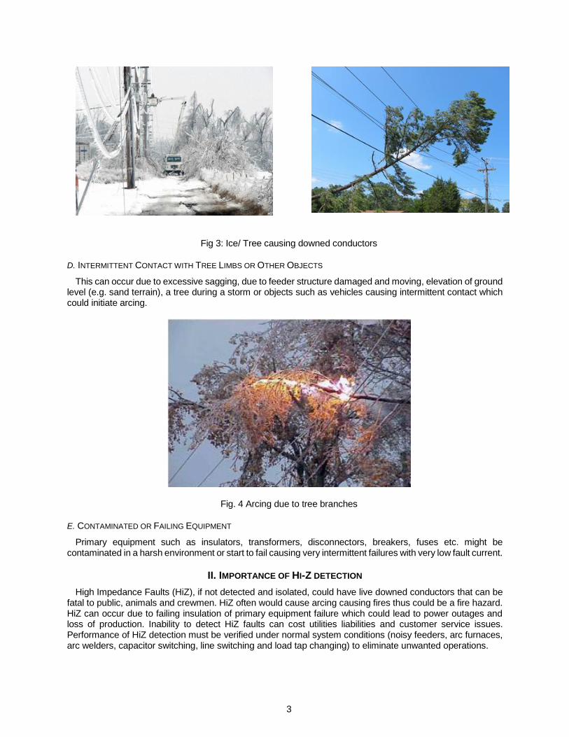
Fig 3: Ice/ Tree causing downed conductors
D. INTERMITTENT CONTACT WITH TREE LIMBS OR OTHER OBJECTS
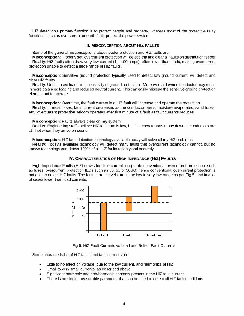
This can occur due to excessive sagging, due to feeder structure damaged and moving, elevation of ground level (e.g. sand terrain), a tree during a storm or objects such as vehicles causing intermittent contact which could initiate arcing.
Fig. 4 Arcing due to tree branches
E. CONTAMINATED OR FAILING EQUIPMENT
Primary equipment such as insulators, transformers, disconnectors, breakers, fuses etc. might be contaminated in a harsh environment or start to fail causing very intermittent failures with very low fault current.
II. IMPORTANCE OF HI-Z DETECTION
High Impedance Faults (HiZ), if not detected and isolated, could have live downed conductors that can be fatal to public, animals and crewmen. HiZ often would cause arcing causing fires thus could be a fire hazard. HiZ can occur due to failing insulation of primary equipment failure which could lead to power outages and loss of production. Inability to detect HiZ faults can cost utilities liabilities and customer service issues. Performance of HiZ detection must be verified under normal system conditions (noisy feeders, arc furnaces, arc welders, capacitor switching, line switching and load tap changing) to eliminate unwanted operations.
4
HiZ detection’s primary function is to protect people and property, whereas most of the protective relay functions, such as overcurrent or earth fault, protect the power system.
III. MISCONCEPTION ABOUT HIZ FAULTS
Some of the general misconceptions about feeder protection and HiZ faults are: Misconception: Properly set, overcurrent protection will detect, trip and clear all faults on distribution feeder Reality: HiZ faults often draw very low current (1 – 100 amps), often lower than loads, making overcurrent
protection unable to detect a large range of HiZ faults. Misconception: Sensitive ground protection typically used to detect low ground current, will detect and
clear HiZ faults Reality: Unbalanced loads limit sensitivity of ground protection. Moreover, a downed conductor may result
in more balanced loading and reduced neutral current. This can easily mislead the sensitive ground protection element not to operate.
Misconception: Over time, the fault current in a HiZ fault will increase and operate the protection. Reality: In most cases, fault current decreases as the conductor burns, moisture evaporates, sand fuses,
etc. overcurrent protection seldom operates after first minute of a fault as fault currents reduces. Misconception: Faults always clear on my system Reality: Engineering staffs believe HiZ fault rate is low, but line crew reports many downed conductors are
still hot when they arrive on scene Misconception: HiZ fault detection technology available today will solve all my HiZ problems Reality: Today’s available technology will detect many faults that overcurrent technology cannot, but no
known technology can detect 100% of all HiZ faults reliably and securely.
IV. CHARACTERISTICS OF HIGH IMPEDANCE (HIZ) FAULTS
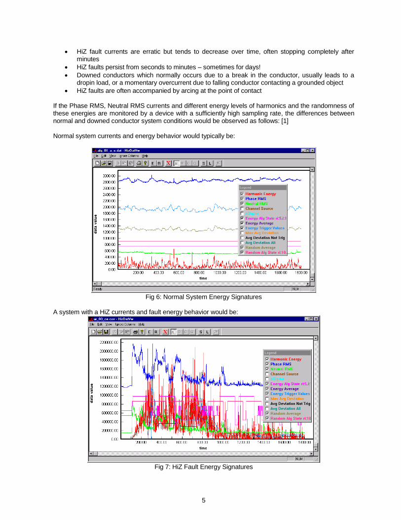
High Impedance Faults (HiZ) draws too little current to operate conventional overcurrent protection, such as fuses, overcurrent protection IEDs such as 50, 51 or 50SG; hence conventional overcurrent protection is not able to detect HiZ faults. The fault current levels are in the low to very low range as per Fig 5, and in a lot of cases lower than load currents.
Fig 5: HiZ Fault Currents vs Load and Bolted Fault Currents Some characteristics of HiZ faults and fault currents are:
• Little to no effect on voltage, due to the low current, and harmonics of HiZ
• Small to very small currents, as described above
• Significant harmonic and non-harmonic contents present in the HiZ fault current
• There is no single measurable parameter that can be used to detect all HiZ fault conditions
5
• HiZ fault currents are erratic but tends to decrease over time, often stopping completely after minutes
• HiZ faults persist from seconds to minutes – sometimes for days!
• Downed conductors which normally occurs due to a break in the conductor, usually leads to a dropin load, or a momentary overcurrent due to falling conductor contacting a grounded object
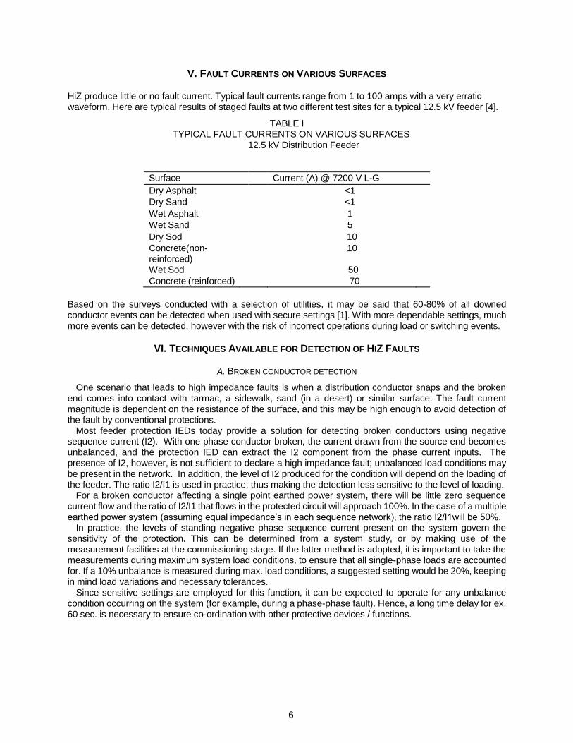
• HiZ faults are often accompanied by arcing at the point of contact If the Phase RMS, Neutral RMS currents and different energy levels of harmonics and the randomness of these energies are monitored by a device with a sufficiently high sampling rate, the differences between normal and downed conductor system conditions would be observed as follows: [1] Normal system currents and energy behavior would typically be:
Fig 6: Normal System Energy Signatures
A system with a HiZ currents and fault energy behavior would be:
Fig 7: HiZ Fault Energy Signatures
6
V. FAULT CURRENTS ON VARIOUS SURFACES
HiZ produce little or no fault current. Typical fault currents range from 1 to 100 amps with a very erratic waveform. Here are typical results of staged faults at two different test sites for a typical 12.5 kV feeder [4].
TABLE I TYPICAL FAULT CURRENTS ON VARIOUS SURFACES
12.5 kV Distribution Feeder
Surface Current (A) @ 7200 V L-G
Dry Asphalt <1
Dry Sand <1
Wet Asphalt 1
Wet Sand 5
Dry Sod 10
Concrete(non-reinforced)
10
Wet Sod 50
Concrete (reinforced) 70
Based on the surveys conducted with a selection of utilities, it may be said that 60-80% of all downed conductor events can be detected when used with secure settings [1]. With more dependable settings, much more events can be detected, however with the risk of incorrect operations during load or switching events.
VI. TECHNIQUES AVAILABLE FOR DETECTION OF HIZ FAULTS
A. BROKEN CONDUCTOR DETECTION
One scenario that leads to high impedance faults is when a distribution conductor snaps and the broken end comes into contact with tarmac, a sidewalk, sand (in a desert) or similar surface. The fault current magnitude is dependent on the resistance of the surface, and this may be high enough to avoid detection of the fault by conventional protections.
Most feeder protection IEDs today provide a solution for detecting broken conductors using negative sequence current (I2). With one phase conductor broken, the current drawn from the source end becomes unbalanced, and the protection IED can extract the I2 component from the phase current inputs. The presence of I2, however, is not sufficient to declare a high impedance fault; unbalanced load conditions may be present in the network. In addition, the level of I2 produced for the condition will depend on the loading of the feeder. The ratio I2/I1 is used in practice, thus making the detection less sensitive to the level of loading.
For a broken conductor affecting a single point earthed power system, there will be little zero sequence current flow and the ratio of I2/I1 that flows in the protected circuit will approach 100%. In the case of a multiple earthed power system (assuming equal impedance’s in each sequence network), the ratio I2/I1will be 50%.
In practice, the levels of standing negative phase sequence current present on the system govern the sensitivity of the protection. This can be determined from a system study, or by making use of the measurement facilities at the commissioning stage. If the latter method is adopted, it is important to take the measurements during maximum system load conditions, to ensure that all single-phase loads are accounted for. If a 10% unbalance is measured during max. load conditions, a suggested setting would be 20%, keeping in mind load variations and necessary tolerances.
Since sensitive settings are employed for this function, it can be expected to operate for any unbalance condition occurring on the system (for example, during a phase-phase fault). Hence, a long time delay for ex. 60 sec. is necessary to ensure co-ordination with other protective devices / functions.
7
B. WATTMETRIC PROTECTION
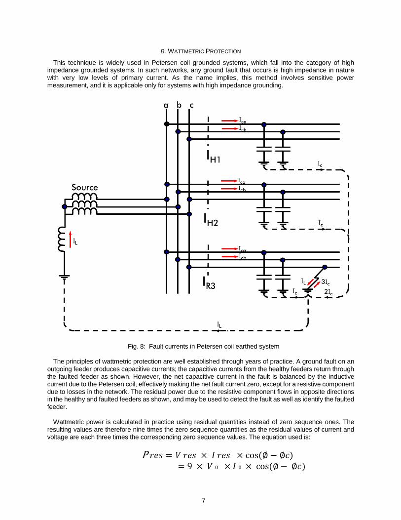
This technique is widely used in Petersen coil grounded systems, which fall into the category of high impedance grounded systems. In such networks, any ground fault that occurs is high impedance in nature with very low levels of primary current. As the name implies, this method involves sensitive power measurement, and it is applicable only for systems with high impedance grounding.
Fig. 8: Fault currents in Petersen coil earthed system
The principles of wattmetric protection are well established through years of practice. A ground fault on an outgoing feeder produces capacitive currents; the capacitive currents from the healthy feeders return through the faulted feeder as shown. However, the net capacitive current in the fault is balanced by the inductive current due to the Petersen coil, effectively making the net fault current zero, except for a resistive component due to losses in the network. The residual power due to the resistive component flows in opposite directions in the healthy and faulted feeders as shown, and may be used to detect the fault as well as identify the faulted feeder.
Wattmetric power is calculated in practice using residual quantities instead of zero sequence ones. The
resulting values are therefore nine times the zero sequence quantities as the residual values of current and voltage are each three times the corresponding zero sequence values. The equation used is:
P 𝑟𝑒𝑠 = 𝑉 𝑟𝑒𝑠 × 𝐼 𝑟𝑒𝑠 × cos(∅ − ∅𝑐)
= 9 × 𝑉 0 × 𝐼 0 × cos(∅ − ∅𝑐)
8
where:
Vres = residual voltage Ires = residual current
Vo = zero sequence voltage Io = zero sequence current
φ = angle between Vres and Ires φc = relay characteristic angle setting
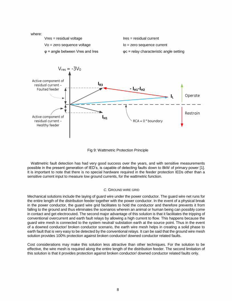
Fig 9: Wattmetric Protection Principle Wattmetric fault detection has had very good success over the years, and with sensitive measurements
possible in the present generation of IED’s, is capable of detecting faults down to 8kW of primary power [1]. It is important to note that there is no special hardware required in the feeder protection IEDs other than a sensitive current input to measure low ground currents, for the wattmetric function.
C. GROUND WIRE GRID
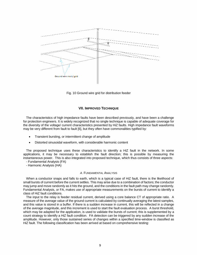
Mechanical solutions include the laying of guard wire under the power conductor. The guard wire net runs for the entire length of the distribution feeder together with the power conductor. In the event of a physical break in the power conductor, the guard wire grid facilitates to hold the conductor and therefore prevents it from falling to the ground and thus eliminates the scenarios wherein an animal or human being can possibly come in contact and get electrocuted. The second major advantage of this solution is that it facilitates the tripping of conventional overcurrent and earth fault relays by allowing a high current to flow. This happens because the guard wire mesh is connected to the system neutral/ substation earth at the source point. Thus in the event of a downed conductor/ broken conductor scenario, the earth wire mesh helps in creating a solid phase to earth fault that is very easy to be detected by the conventional relays. It can be said that the ground wire mesh solution provides 100% protection against broken conductor/ downed conductor related faults. Cost considerations may make this solution less attractive than other techniques. For the solution to be effective, the wire mesh is required along the entire length of the distribution feeder. The second limitation of this solution is that it provides protection against broken conductor/ downed conductor related faults only.
Vres = -3V0
IH1
IL
- IH1-IH2
IR3
Operate
Restrain
Active component of residual current –
Faulted feeder
Active component of residual current –
Healthy feederRCA = 0 ° boundary
9
Fig. 10 Ground wire grid for distribution feeder
VII. IMPROVED TECHNIQUE
The characteristics of high impedance faults have been described previously, and have been a challenge
for protection engineers. It is widely recognized that no single technique is capable of adequate coverage for the diversity of the voltage/ current characteristics presented by HiZ faults. High impedance fault waveforms may be very different from fault to fault [6], but they often have commonalities typified by:
• Transient bursting, or intermittent change of amplitude
• Distorted sinusoidal waveform, with considerable harmonic content
The proposed technique uses these characteristics to identify a HiZ fault in the network. In some applications, it may be necessary to establish the fault direction; this is possible by measuring the instantaneous power. This is also integrated into proposed technique, which thus consists of three aspects:
- Fundamental Analysis (FA) - Harmonic Analysis (HA)
A. FUNDAMENTAL ANALYSIS
When a conductor snaps and falls to earth, which is a typical case of HiZ fault, there is the likelihood of small bursts of current before the current settles. This may arise due to a combination of factors; the conductor may jump and move randomly as it hits the ground, and the conditions in the fault path may change randomly. Fundamental Analysis, or FA, makes use of appropriate measurements on the bursts of current to identify a class of HiZ fault conditions.
The input to the relay is feeder residual current, derived using a core balance CT of appropriate ratio. A measure of the average value of the ground current is calculated by continually averaging the latest samples, and this value is stored in a buffer. If there is a sudden increase in current, this will be reflected in a change of the average magnitude, and this increment is used to start the fault evaluation process. A burst threshold, which may be adapted for the application, is used to validate the bursts of current; this is supplemented by a count strategy to identify a HiZ fault condition. FA detection can be triggered by any sudden increase of the amplitude. However, only those sustained series of changes within a specified time-window is classified as HiZ fault. The following classification has been arrived at based on comprehensive testing:
10
Event Classification Criterion
HiZ Fault Bursts exceed set count within time limit
Transient Event Bursts do not exceed count, but two or more bursts counted
Steady Event Burst threshold exceeded
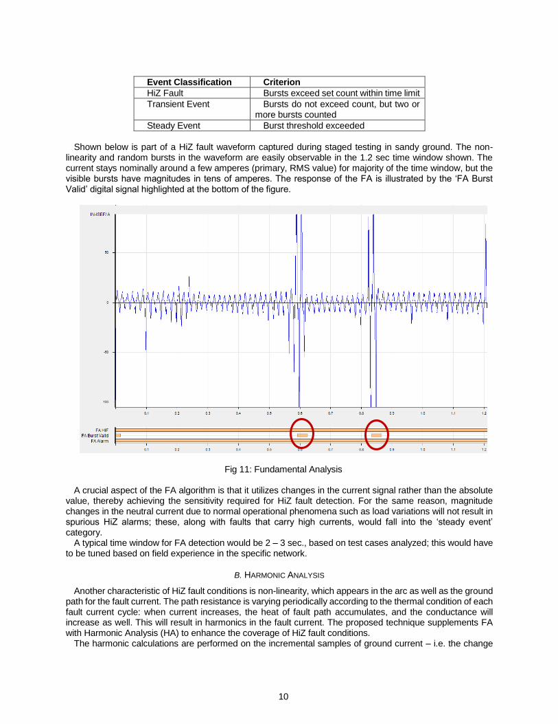
Shown below is part of a HiZ fault waveform captured during staged testing in sandy ground. The non-
linearity and random bursts in the waveform are easily observable in the 1.2 sec time window shown. The current stays nominally around a few amperes (primary, RMS value) for majority of the time window, but the visible bursts have magnitudes in tens of amperes. The response of the FA is illustrated by the ‘FA Burst Valid’ digital signal highlighted at the bottom of the figure.
Fig 11: Fundamental Analysis
A crucial aspect of the FA algorithm is that it utilizes changes in the current signal rather than the absolute value, thereby achieving the sensitivity required for HiZ fault detection. For the same reason, magnitude changes in the neutral current due to normal operational phenomena such as load variations will not result in spurious HiZ alarms; these, along with faults that carry high currents, would fall into the ‘steady event’ category.
A typical time window for FA detection would be 2 – 3 sec., based on test cases analyzed; this would have to be tuned based on field experience in the specific network.
B. HARMONIC ANALYSIS
Another characteristic of HiZ fault conditions is non-linearity, which appears in the arc as well as the ground path for the fault current. The path resistance is varying periodically according to the thermal condition of each fault current cycle: when current increases, the heat of fault path accumulates, and the conductance will increase as well. This will result in harmonics in the fault current. The proposed technique supplements FA with Harmonic Analysis (HA) to enhance the coverage of HiZ fault conditions.
The harmonic calculations are performed on the incremental samples of ground current – i.e. the change
11
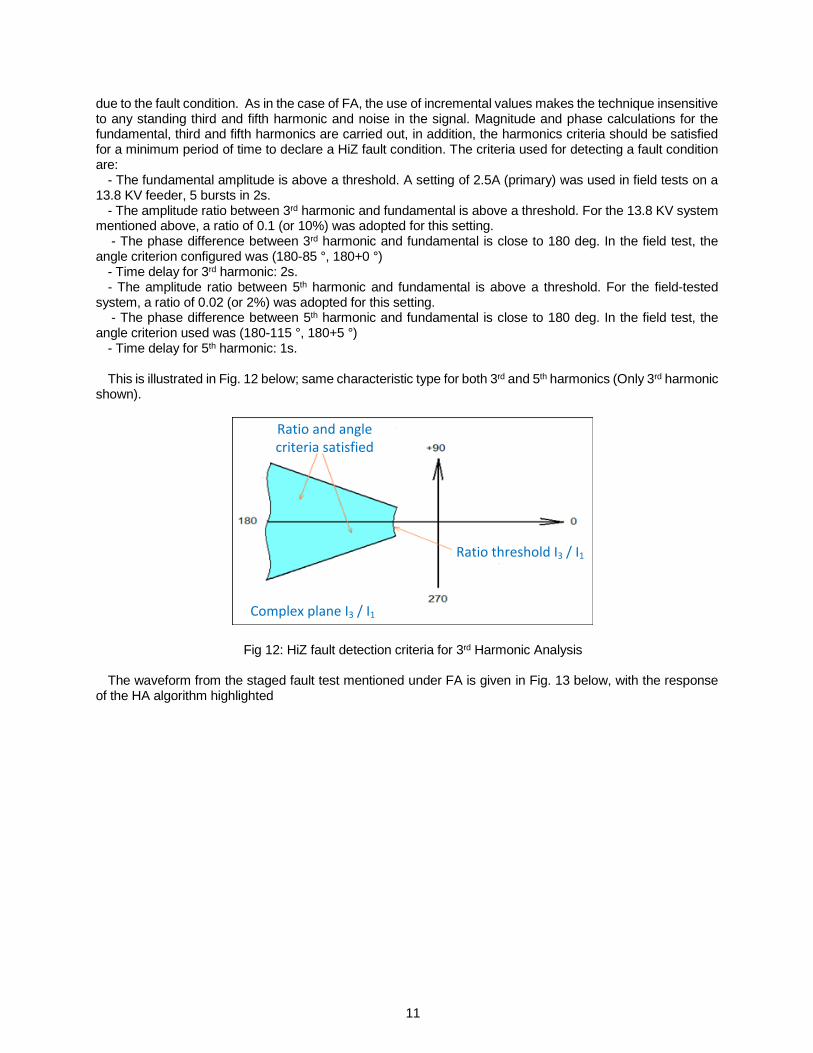
due to the fault condition. As in the case of FA, the use of incremental values makes the technique insensitive to any standing third and fifth harmonic and noise in the signal. Magnitude and phase calculations for the fundamental, third and fifth harmonics are carried out, in addition, the harmonics criteria should be satisfied for a minimum period of time to declare a HiZ fault condition. The criteria used for detecting a fault condition are:
- The fundamental amplitude is above a threshold. A setting of 2.5A (primary) was used in field tests on a 13.8 KV feeder, 5 bursts in 2s.
- The amplitude ratio between 3rd harmonic and fundamental is above a threshold. For the 13.8 KV system mentioned above, a ratio of 0.1 (or 10%) was adopted for this setting.
- The phase difference between 3rd harmonic and fundamental is close to 180 deg. In the field test, the angle criterion configured was (180-85 °, 180+0 °)
- Time delay for 3rd harmonic: 2s. - The amplitude ratio between 5th harmonic and fundamental is above a threshold. For the field-tested
system, a ratio of 0.02 (or 2%) was adopted for this setting. - The phase difference between 5th harmonic and fundamental is close to 180 deg. In the field test, the
angle criterion used was (180-115 °, 180+5 °) - Time delay for 5th harmonic: 1s. This is illustrated in Fig. 12 below; same characteristic type for both 3rd and 5th harmonics (Only 3rd harmonic
shown).
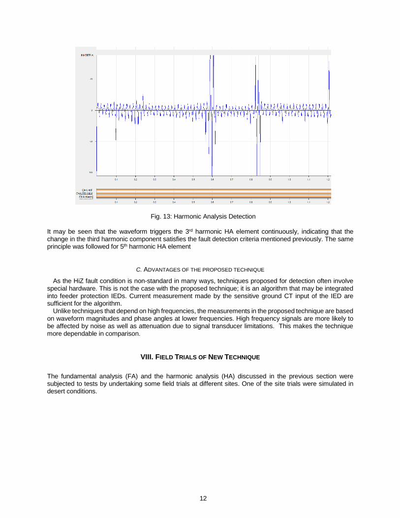
Fig 12: HiZ fault detection criteria for 3rd Harmonic Analysis The waveform from the staged fault test mentioned under FA is given in Fig. 13 below, with the response
of the HA algorithm highlighted
Complex plane I3 / I1
Ratio and angle criteria satisfied
Ratio threshold I3 / I1
12
Fig. 13: Harmonic Analysis Detection
It may be seen that the waveform triggers the 3rd harmonic HA element continuously, indicating that the change in the third harmonic component satisfies the fault detection criteria mentioned previously. The same principle was followed for 5th harmonic HA element
C. ADVANTAGES OF THE PROPOSED TECHNIQUE
As the HiZ fault condition is non-standard in many ways, techniques proposed for detection often involve special hardware. This is not the case with the proposed technique; it is an algorithm that may be integrated into feeder protection IEDs. Current measurement made by the sensitive ground CT input of the IED are sufficient for the algorithm.
Unlike techniques that depend on high frequencies, the measurements in the proposed technique are based on waveform magnitudes and phase angles at lower frequencies. High frequency signals are more likely to be affected by noise as well as attenuation due to signal transducer limitations. This makes the technique more dependable in comparison.
VIII. FIELD TRIALS OF NEW TECHNIQUE
The fundamental analysis (FA) and the harmonic analysis (HA) discussed in the previous section were subjected to tests by undertaking some field trials at different sites. One of the site trials were simulated in desert conditions.
13
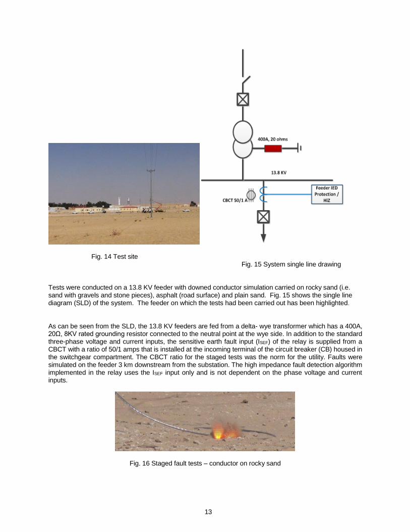
Fig. 14 Test site Fig. 15 System single line drawing Tests were conducted on a 13.8 KV feeder with downed conductor simulation carried on rocky sand (i.e. sand with gravels and stone pieces), asphalt (road surface) and plain sand. Fig. 15 shows the single line diagram (SLD) of the system. The feeder on which the tests had been carried out has been highlighted.
As can be seen from the SLD, the 13.8 KV feeders are fed from a delta- wye transformer which has a 400A, 20Ω, 8KV rated grounding resistor connected to the neutral point at the wye side. In addition to the standard three-phase voltage and current inputs, the sensitive earth fault input (ISEF) of the relay is supplied from a CBCT with a ratio of 50/1 amps that is installed at the incoming terminal of the circuit breaker (CB) housed in the switchgear compartment. The CBCT ratio for the staged tests was the norm for the utility. Faults were simulated on the feeder 3 km downstream from the substation. The high impedance fault detection algorithm implemented in the relay uses the ISEF input only and is not dependent on the phase voltage and current inputs.
Fig. 16 Staged fault tests – conductor on rocky sand
14
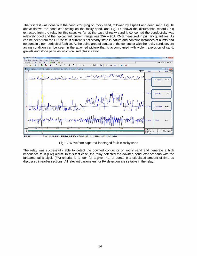
The first test was done with the conductor lying on rocky sand, followed by asphalt and deep sand. Fig. 16 above shows the conductor arcing on the rocky sand, and Fig. 17 shows the disturbance record (DR) extracted from the relay for this case. As far as the case of rocky sand is concerned the conductivity was relatively good and the typical fault current range was 25A – 90A RMS measured in primary quantities. As can be seen from the DR the fault current is not steady state in nature and contains instances of bursts and no burst in a non-periodical fashion. At the point/ area of contact of the conductor with the rocky sand, severe arcing condition can be seen in the attached picture that is accompanied with violent explosion of sand, gravels and stone particles which caused glassification.
Fig. 17 Waveform captured for staged fault in rocky sand The relay was successfully able to detect the downed conductor on rocky sand and generate a high impedance fault (HiZ) alarm. In this test case, the relay detected the downed conductor scenario with the fundamental analysis (FA) criteria, is to look for a given no. of bursts in a stipulated amount of time as discussed in earlier sections. All relevant parameters for FA detection are settable in the relay.
15
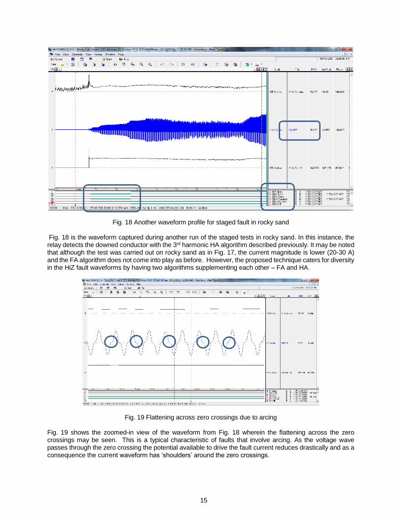
Fig. 18 Another waveform profile for staged fault in rocky sand
Fig. 18 is the waveform captured during another run of the staged tests in rocky sand. In this instance, the relay detects the downed conductor with the 3rd harmonic HA algorithm described previously. It may be noted that although the test was carried out on rocky sand as in Fig. 17, the current magnitude is lower (20-30 A) and the FA algorithm does not come into play as before. However, the proposed technique caters for diversity in the HiZ fault waveforms by having two algorithms supplementing each other – FA and HA.
Fig. 19 Flattening across zero crossings due to arcing Fig. 19 shows the zoomed-in view of the waveform from Fig. 18 wherein the flattening across the zero crossings may be seen. This is a typical characteristic of faults that involve arcing. As the voltage wave passes through the zero crossing the potential available to drive the fault current reduces drastically and as a consequence the current waveform has ‘shoulders’ around the zero crossings.
16
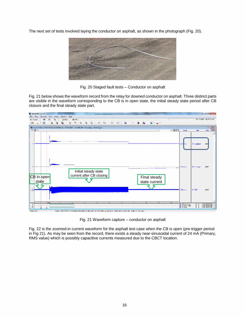
The next set of tests involved laying the conductor on asphalt, as shown in the photograph (Fig. 20).
Fig. 20 Staged fault tests – Conductor on asphalt
Fig. 21 below shows the waveform record from the relay for downed conductor on asphalt. Three distinct parts are visible in the waveform corresponding to the CB is in open state, the initial steady state period after CB closure and the final steady state part.
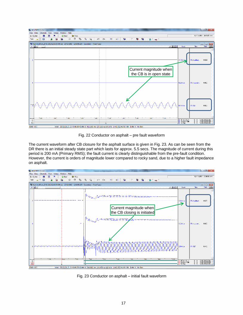
Fig. 21 Waveform capture – conductor on asphalt Fig. 22 is the zoomed-in current waveform for the asphalt test case when the CB is open (pre-trigger period in Fig 21). As may be seen from the record, there exists a steady near-sinusoidal current of 24 mA (Primary, RMS value) which is possibly capacitive currents measured due to the CBCT location.
CB in open state
Initial steady state current after CB closing
Final steady state current
17
Fig. 22 Conductor on asphalt – pre fault waveform The current waveform after CB closure for the asphalt surface is given in Fig. 23. As can be seen from the DR there is an initial steady state part which lasts for approx. 5.5 secs. The magnitude of current during this period is 200 mA (Primary RMS); the fault current is clearly distinguishable from the pre-fault condition. However, the current is orders of magnitude lower compared to rocky sand, due to a higher fault impedance on asphalt.
Fig. 23 Conductor on asphalt – initial fault waveform
Current magnitude when the CB is in open state
Current magnitude when the CB closing is initiated

18
Fig. 24 shows the waveform capture of the final steady state part of the fault current. The magnitude of fault current during this period is approx.17 mA (Primary RMS).
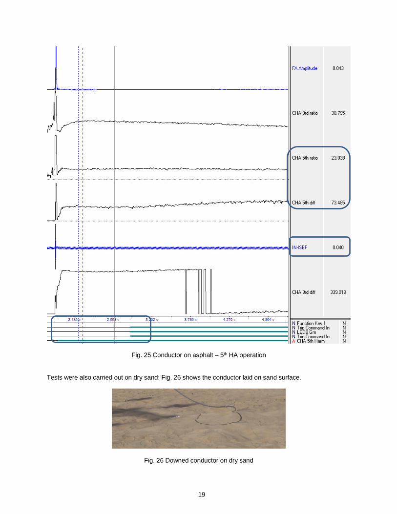
Fig. 24 Conductor on asphalt – fault waveform In this test case, the fault current was too low for the 3rd harmonic HA element. With the addition of the 5th harmonic HA element, HiZ operated as in Fig. 25. In this case, the primary fault current was 40mA RMS, however the 5th harmonic component did detect a significant level of 5th harmonics (23%) with the phase angle difference in the operating region (73deg).
Final steady state current magnitude
Initial steady state current magnitude ≈ 0.200 amp (primary)
19
Fig. 25 Conductor on asphalt – 5th HA operation Tests were also carried out on dry sand; Fig. 26 shows the conductor laid on sand surface.
Fig. 26 Downed conductor on dry sand
20
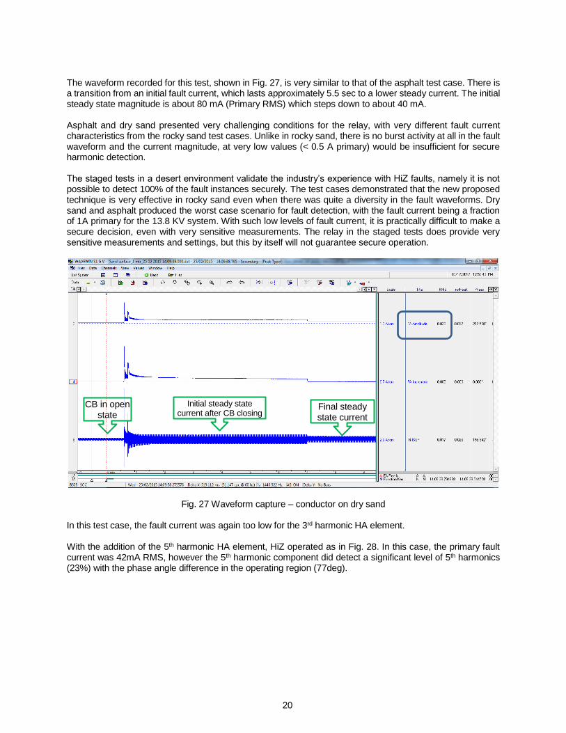
The waveform recorded for this test, shown in Fig. 27, is very similar to that of the asphalt test case. There is a transition from an initial fault current, which lasts approximately 5.5 sec to a lower steady current. The initial steady state magnitude is about 80 mA (Primary RMS) which steps down to about 40 mA. Asphalt and dry sand presented very challenging conditions for the relay, with very different fault current characteristics from the rocky sand test cases. Unlike in rocky sand, there is no burst activity at all in the fault waveform and the current magnitude, at very low values (< 0.5 A primary) would be insufficient for secure harmonic detection. The staged tests in a desert environment validate the industry’s experience with HiZ faults, namely it is not possible to detect 100% of the fault instances securely. The test cases demonstrated that the new proposed technique is very effective in rocky sand even when there was quite a diversity in the fault waveforms. Dry sand and asphalt produced the worst case scenario for fault detection, with the fault current being a fraction of 1A primary for the 13.8 KV system. With such low levels of fault current, it is practically difficult to make a secure decision, even with very sensitive measurements. The relay in the staged tests does provide very sensitive measurements and settings, but this by itself will not guarantee secure operation.
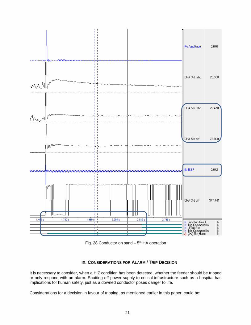
Fig. 27 Waveform capture – conductor on dry sand In this test case, the fault current was again too low for the 3rd harmonic HA element. With the addition of the 5th harmonic HA element, HiZ operated as in Fig. 28. In this case, the primary fault current was 42mA RMS, however the 5th harmonic component did detect a significant level of 5th harmonics (23%) with the phase angle difference in the operating region (77deg).
CB in open state
Initial steady state current after CB closing
Final steady state current
21
Fig. 28 Conductor on sand – 5th HA operation
IX. CONSIDERATIONS FOR ALARM / TRIP DECISION
It is necessary to consider, when a HiZ condition has been detected, whether the feeder should be tripped or only respond with an alarm. Shutting off power supply to critical infrastructure such as a hospital has implications for human safety, just as a downed conductor poses danger to life.
Considerations for a decision in favour of tripping, as mentioned earlier in this paper, could be:
22
• Mitigate or prevent danger to human and animal life.
• Preventing wildfires or damage to property
• Limiting any legal liability and litigation
However, the case for tripping is not simple or straightforward, as may be seen below:
• Impact on supply continuity. There may be contractual commitments on service continuity that may be violated if the feeder is tripped.
• As HiZ faults produces relatively low current, there is very little risk of damage to assets.
• Settings for HiZ protection are not easy to arrive at, or standardize. Opting for trips may result in unwanted relay operations in some instances.
• HiZ faults downstream of fuses or close to the tail end of the distribution feeders may be difficult to identify.
A practical option to consider would be to make the trip/alarm policy application specific. Considerations for such a policy could be the criticality of the loads served by the feeder or its geographical routing (through built-up areas, for example). If HiZ protection is being rolled out for the first time or trialled, the preference would be for alarm only until such a time the relay settings have been tuned and the relay function has proved itself.
X. CONCLUSION
There is considerable interest in HiZ detection from various parts of the world, due to better awareness of the fault condition as well as growing safety considerations, especially in the developing world. High impedance faults produce very low levels of current and are generally not detected by standard feeder protection functions such as overcurrent or sensitive ground elements. In fact, the behavior of HiZ faults is quite diverse, and there is general agreement that no single technique is capable of securely identifying all HiZ fault scenarios. However, a large percentage of HiZ faults can be detected; utilities which presently do not employ any form of HiZ detection will significantly benefit from rolling out available technologies. A new technique has been proposed, using sensitive current measurement in a standard feeder protection device. The technique makes use of typical characteristics of HiZ faults, and does not require any special hardware or waveform sampling in the protection device. Successful field trials have been conducted to validate the effectiveness of the technique, which utilizes changes in fault parameters to enhance the sensitivity of fault detection.
XI. REFERENCES
[1] Cigre Working Group B5.94, "Hight Impedance Faults", December 2009. [2] PSRC Working Group D15, "High Impedance Fault Detection Technology ", IEEE Power Systems
Relaying Committee, March 1996. [3] MiCOM P40 Agile P14D Instruction Manual, Publication Reference P14D-TM-EN-8. [4] Detection of High Impedance Faults in MV Distribution Systems, S.Subramanian, K. Venkataraman, 11th
International Conference on Developments in Power System Protection, April 2012 [5] EDF’s field experience on MV Networks Zero Sequence Protection Scheme; L. Karsenti, P. Kabanac -
CIRED 19th International Conference on Electricity Distribution, May 2007 [6] CHARACTERISATION OF HIGH IMPEDANCE FAULTS IN SOLIDLY GROUNDED DISTRIBUTION
NETWORKS: A. Masa, J. Maun, S. Werben – 17th Power Systems Computation Conference, Sweden, Aug 2011
23
XII. AUTHORS’ INFORMATION
JC (Jacobus) Theron is Technical Applications Engineer for Grid Automation division of GE Grid Solutions. He received the degree of Electrical and Electronic Engineer from the University of Johannesburg, South Africa in 1991. Mr. Theron has 25 years of engineering experience; 6 years with Eskom (South Africa) as Protection / Control and Metering Engineer, 11 years with GE Multilin (Canada) as Product / Technical support / Protective Relaying Consultant/Protection and Systems Engineer leading the Project and Consulting Engineering team and as Product Manager, 2 years with Alstom T&D (USA) as Senior Systems Engineer and 5 years with Hydro One as Operations Assessment Engineer / P&C Technical Services Manager. He specializes in transmission, distribution, bus and rotating machines protection applications support and Fast Load Shed Systems, system designs and transient system testing
Amit Pal Amit graduated in Electrical engineering in the year 2002 from Nagpur University. Post graduation
he was involved in one year apprenticeship training in an industry related to defense. Later he was involved in testing and commissioning related activities of primary equipments, switchgears, transformers, control n relay panels, protection relay testing etc. in generating stations and EHV substations across major states in India. From 2006 till present he is with GE as product application engineer looking for product related support, testing, analysis and development.
Abraham Varghese is the Global Utility Applications Leader for the Grid Automation division of GE Grid
Solutions, with responsibility for worldwide application support on GE’s protection devices portfolio. He has been active in the power system protection domain for more than two decades across various functions - Business Development, Subject Matter Expert (Automation), Engineering and Services. Abraham is based in Stafford, U.K. for the last 11 years with GE (Alstom), prior to which he was working with GE Energy Substation Automation group in the U.K. His recent activities include product management of IEC 61850 Process Bus developments such as the analogue merging unit and protection relays with IEC 61850-9-2LE interface. Abraham holds a Ph. D. in Electrical Engineering from the University of Illinois at Urbana-Champaign, U.S.A. and is a Senior Member of the IEEE, U.S.A. His current interests include Digital Substation, IEC 61850 Process Bus and transmission protection applications.


![Enhance High Impedance Fault Detection and …yweng2/papers/2019TSG-PMU.pdfalgorithm [2], impedance-based method [3] and PC-based fault locating and diagnosis algorithm [4], etc. However,](https://img.pdfslide.us/doc/110x75/5fe122d4df236711b2274e10/enhance-high-impedance-fault-detection-and-yweng2papers2019tsg-pmupdf-algorithm.jpg)