Embed Size (px)
Citation preview
Written by: [email protected] Revision/release date: A, 2016.08.18
Tutorial n°5
SIMULATION AND CONTROL CODE GENERATION FOR A GRID-TIED 3-PHASE SOLAR INVERTER USING SIMULINK Written by: imperix SA, Rte. de l’Industrie 17, 1950 Sion, Switzerland Matthias Lambert <[email protected]> Addressed topics: Use of the BoomBox Simulink libraries Association with Typhoon HIL emulators Comparison of simulation and HIL results
1 INTRODUCTION This tutorial presents a control implementation for a three-phase grid-tied inverter using Simulink and the BoomBox control platform. The BoomBox development environment allows the same control implementation to be used in simulation, as well as to be run directly on a BoomBox. In the first case, the converter can be modeled inside Simulink, while a Hardware In-The-Loop (HIL) simulator is connected to the BoomBox in the second case. The considered system is depicted in Figure 1. Its main electrical parameters are shown in Table 1:
Figure 1 : Simplified electrical scheme of the considered system.
Figure 2 : Picture of a test setup using a Typhoon HIL400, emulating the power electronics converters. Only one
BoomBox is utilized in the presented example.

APPLICATION EXAMPLE
Simulation and control code generation for a grid-tied 3-phase solar inverter using Simulink
2
Name Nom. value Specification Employed sensor Channel #
Ug 230 VRMS (l-n) Grid voltage (line-to-neutral) IX-DIN800V 5, 6, 7 Ig 30 ARMS Current injected into the grid (phase) IX-DIN50A 2, 3, 4 UDC 650 VDC DC bus voltage IX-DIN800V 10 UPV1,2 350-650 V Voltage(s) on the photovoltaic panels IX-DIN800V 8, 9 IPV1,2 20A Current(s) extracted from the PV panels IX-DIN50A 0, 1 fS 4 kHz Switching frequency N.A. N.A. Lg 4 mH Filtering inductor N.A. N.A. Lpv 4 mH Filtering inductor N.A. N.A.
Table 1 : Electrical parameters of the studied system.
The proposed control strategy controls the grid current in a rotating reference frame (DQ-type) that is synchronized with the grid voltage. This synchronization is achieved by a software phase-locked loop (PLL). This conventional approach is well described in [1]. The equivalent scheme is shown in Figure 3:
Figure 3 : Implemented control strategy for the three-phase inverter. Source [1].
Additionally, both photovoltaic strings rely on a PI-type current control. In this example, all functional blocs constituting the control implementations have been translated in a Simulink implementation using the BoomBox library and standard Simulink blocks. This shows that the control implementation of such a power conversion structure can be easily achieved, thanks to the BoomBox development environment.

APPLICATION EXAMPLE
Simulation and control code generation for a grid-tied 3-phase solar inverter using Simulink
3
2 HARDWARE SET-UP When associated to an emulation device such as a Hardware In-The-Loop (HIL) simulator, the set-up is trivial. The BoomBox simply needs to be connected to the emulator. For Typhoon HIL devices, the necessary cabling interface is even available among the BoomBox accessories.
As presented in the previous tutorials, the configuration of the BoomBox’s analog inputs depends on the measurement sensors, which are here directly emulated by the HIL device. A possible configuration is given in Table 2. This approach guarantees a maximum compatibility with the final application by configuring the emulator so that the output gains for each measurement also emulates the final – and real – sensor. The configuration of the utilized Typhoon HIL 400 is shown in Table 3:
Type # Channel Bbox Sensor (fictive) Sensitivity Limits Bbox gain Bbox limits
Current 0 to 4 IX-DIN50A 100 [mV/A] Various 2.0 Various Voltage 5 to 10 IX-DIN800V 2.46 [mV/V] Various 4.0 Various
Table 2 : Configuration parameters of the BoomBox (analog inputs).
Type # Channel HIL Sensitivity to emulate Output gain of the emulator
Current 1 to 5 100 [mV/A] ÷ 10 Voltage 6 to 11 2.46 [mV/V] ÷ 407
Table 3 : Configuration parameters of the Typhoon HIL 400 emulator (analog outputs).
Note: The Typhoon HIL emulator HIL400 and HIL600 have their output voltage limited to ±5V, instead of ±10V for the newer generations HIL402 and HIL602. This particularity may impose additional restrictions that must be taken into account.
3 SOFTWARE CONFIGURATION
3.a CONFIGURATION OF THE TIME BASES In Simulink, time bases are configured by double-clicking the Configuration block. Two distinct time bases co-exist:
a) The simulation step size corresponds to the update rate of the outputs of the PWM blocks in Simulation mode; it has no effect in Automated Code Generation mode. Con-sequently, the model of the converter plant connected to the simulated PWM outputs should be running at this same step size. If using a package requiring a specific configu-ration, a variable named TSAMPLE can be used to define the sample time of the simulat-ed model.
b) The switching frequency can be chosen in the second tab of the Configuration block. This sets the carrier frequency of the PWM modulators, as well as the execution frequen-cy of the control algorithms, both in Simulation and in Automated Code Generation modes.

APPLICATION EXAMPLE
Simulation and control code generation for a grid-tied 3-phase solar inverter using Simulink
4
Figure 4 : Configuration block of the BoomBox library showing the mode selection and time base settings.
The sampling phase sets at which instant in the switching period the analog inputs are sampled. The execution of the control algorithms directly follows the acquisition. Sampling can be advantageously made at the beginning or the middle of the switching period, i.e. the exact instants when the current – including its ripple – is equal to its sliding-average value. In this case, the sampling is configured in the middle of the period. As PWM parameters are applied at the beginning of the switching period, (phase=0), the control algorithm has half a period to do its job, e.g. 125 µs.
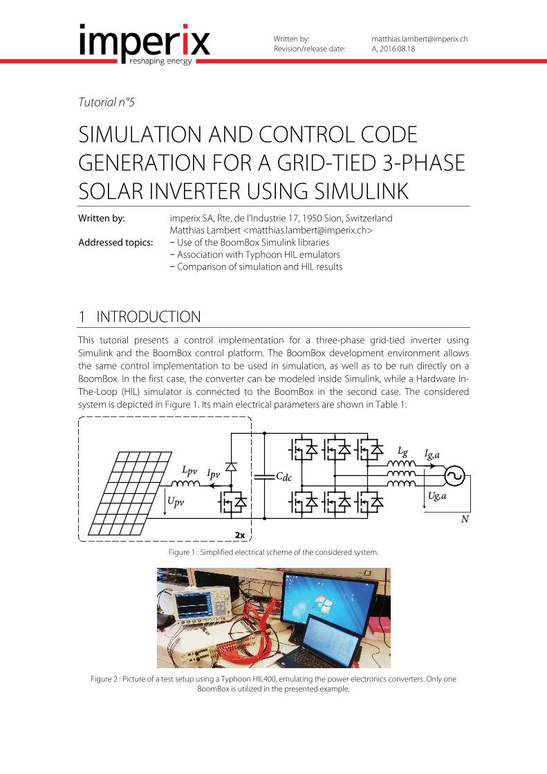
3.b CONFIGURATION OF THE PULSE-WIDTH MODULATORS PWM modulators are configured by double-clicking them. In this example, triangular carriers and 1 µs deadtimes are implemented on all channels.
APPLICATION EXAMPLE
Simulation and control code generation for a grid-tied 3-phase solar inverter using Simulink
5
Figure 5 : Configuration of a PWM modulator.
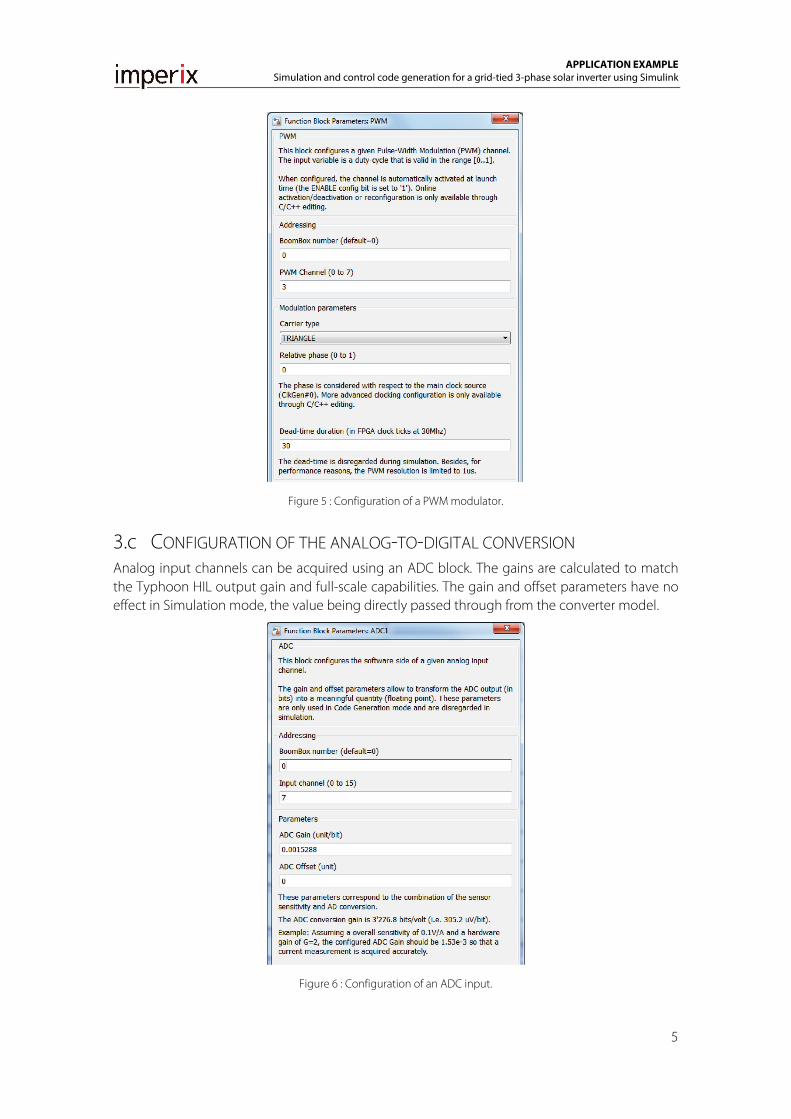
3.c CONFIGURATION OF THE ANALOG-TO-DIGITAL CONVERSION Analog input channels can be acquired using an ADC block. The gains are calculated to match the Typhoon HIL output gain and full-scale capabilities. The gain and offset parameters have no effect in Simulation mode, the value being directly passed through from the converter model.
Figure 6 : Configuration of an ADC input.

APPLICATION EXAMPLE
Simulation and control code generation for a grid-tied 3-phase solar inverter using Simulink
6
4 IMPLEMENTATION OF THE CONTROL
4.a IMPLEMENTATION OF THE CLOSED-LOOP CONTROL
Figure 7 : Overview of the closed-loop control implementation in Simulink.
The closed-loop control for the system is implemented as described in §1.
The main differences with the C version of this tutorial (Tutorial n°3) are the lack of MPPT algorithm and state machine. The implemented control corresponds to the TRACKING state as defined in the C code.
At the top-left of Figure 7 is the Configuration block. This is where the user can configure the time bases and the mode of operation of the model (see §3.a). This blocks also provides clock outputs to be connected to the corresponding inputs of ADC and PWM blocks. This is used to provide the appropriate ADC sampling and PWM carrier timing signals used in Simulation mode.
On the left are the analog inputs that operate both in Simulation mode by copying their input to their output, and in Automated Code Generation where they are translated into calls to the BoomBox library to acquire the BoomBox’s ADC inputs.
On the right, the PWM blocks work in a similar way, providing a simulated version of the PWM output to the system in Simulation mode, while producing the real output on the BoomBox when code is generated.
In the middle, the control is implemented using blocks from both the BoomBox library and the standard Simulink library. Coordinate transformations are conveniently provided in the BoomBox library:
Figure 8 : Example of a coordinate transformation block (abc-to-dq0) from the BoomBox library.

APPLICATION EXAMPLE
Simulation and control code generation for a grid-tied 3-phase solar inverter using Simulink
7
PV current controllers are implemented using simple PI regulators from the standard Simulink library, wired in a feedforward configuration:
Figure 9: Example of a simple PI current controller.
The only non-standard block shown in Figure 9 is the Tunable parameter block from the BoomBox library. This allows to define a constant reference parameter that can then be dynamically altered while the code is running on the BoomBox using the BoomBox Control graphical software.
Similarly, if the value of a wire in the Simulink model needs to be monitored in real-time once the code is running in the BoomBox, a Probe block from the BoomBox library can be used (see Iq_d and Iq_q on Figure 11). The name given to the Probe element can then be found in BoomBox Control to watch and datalog its value.
The control of the inverter is made of a PLL block and a DQ current control block:
Figure 10: Example of an inverter current control.
Figure 11: Inside the DQ current control block.

APPLICATION EXAMPLE
Simulation and control code generation for a grid-tied 3-phase solar inverter using Simulink
8
The DC-bus voltage control is a simple PI controller that gives the reference for the inverter d-axis current (active power injected to the grid) so as to keep the DC-bus voltage constant.
5 SIMULATION OF THE CONVERTERS
Figure 12: Model of the converter using SimScape PowerSystems.
The simulated model of the converter takes as input the simulated PWM signals from the control part and produces simulated analog measurements. As said in §3.a, the SimScape PowerSystems package needs to be configured with the correct sample time. This is done in the powergui block:
Figure 13 : Example configuration of the powergui block of the SimScape Power Systems package.
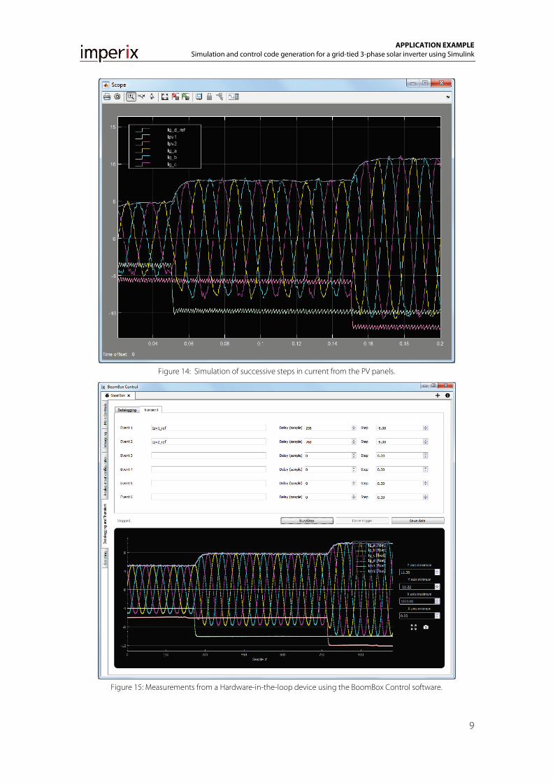
6 RESULTS The following results were obtained two different ways. The first one using Simulation mode and the SimScape PowerSystems package to simulate the converter. The second one running the generated controller code directly on the BoomBox and simulating the converter using a Typhoon HIL 402 device.
The steps applied on the PV current references were generated using standard Simulink step blocks in simulation, while the transient generator of the BoomBox Control software was used in the case of the HIL setup.
The Simulink model file was kept identical between the two tests.
APPLICATION EXAMPLE
Simulation and control code generation for a grid-tied 3-phase solar inverter using Simulink
9
Figure 14: Simulation of successive steps in current from the PV panels.
Figure 15: Measurements from a Hardware-in-the-loop device using the BoomBox Control software.

APPLICATION EXAMPLE
Simulation and control code generation for a grid-tied 3-phase solar inverter using Simulink
10
7 REFERENCES [1] R. Teodorescu, M. Liserre and P. Rodríguez, and P. C. Loh, “Grid converters for photovoltaic and wind
power systems,” Wiley, 2011, 407p.