Embed Size (px)
Citation preview
Interplay between reactivity and transport phenomena in heterogeneous catalysis
Matteo Maestri
July 23, 2013 Conversationshaus - Norderney, Germany
Tutorial lecture on

Chemical reactor The reactor is the device within which the physicochemical transformations are caused. It can assume various shapes and modes of operations and be operated in a number of possible environments of pressure and temperature.
(images from internet)

Heterogeneous catalytic reactor
B A
REACTOR
CATALYST SUPPORT: ACTIVE SITES ARE DEPOSITED WITHIN THESE POROUS SOLIDS
Heterogeneous catalytic reactions by their nature involve a separate phase of catalyst embedded in a phase of
reacting species.

Film diffusion
Pore diffusion
Adsorption/ desorption
Boundary layer
Porous catalyst
Active sites
Chemical reaction
1
4
7
2 6
3 5
The way to the active sites
B A
B* A*

Film diffusion
Pore diffusion
Adsorption/ desorption
Boundary layer
Porous catalyst
Active sites
Chemical reaction
1
4
7
2 6
3 5
The way to the active sites
B A
B* A*

Film diffusion
Pore diffusion
Adsorption/ desorption
Boundary layer
Porous catalyst
Active sites
Chemical reaction
1
4
7
2 6
3 5
The way to the active sites
B A
B* A*
The observable reaction rate may differ
substantially from the intrinsic rate of
chemical transformation under bulk fluid
phase conditions.

Catalysts at work
Film diffusion
Pore diffusion
Adsorption/desorption
Boundarylayer
Porouscatalyst
Active sites
Chemical reaction
1
4
7
2 6
3 5
BA
BA
B A
How do transport phenomena and distribution of residence times in the reactor affect the observed reaction rate?

Outline
1) Effect of the distribution of the contact times in the reactor on the observed reaction rate
2) Inter-phase and intra-phase transport phenomena and their impact on the observed reaction rate
3) Show-case: effect of transport phenomena on catalyst reactivity
4) Take-home messages

Reactivity (for this talk)
3 [mol/m / ]Ar kc s=
A → B
0 exp Ek kRT
= −
A
B
E
Reaction coordinate

Outline
1) Effect of the distribution of the contact times in the reactor on the observed reaction rate
2) Inter-phase and intra-phase transport phenomena and their impact on the observed reaction rate
3) Show-case: effect of transport phenomena on catalyst reactivity
4) Take-home messages

How long molecules stay in the reactor?
PLUG-FLOW-REACTOR: all molecules have same residence time and concetrations vary only along the length of the tubular reactor.
CONTINUOUS-FLOW STIRRED TANK REACTOR: due to vigorous agitation, the reactor contents are well mixed, so that effluent composition equals that in the tank

Residence time distribution in PFR
Time
INLET
0
x
V
Q

Residence time distribution in PFR
Time Time
INLET OUTLET
0
x
V
Q

Residence time distribution in PFR
Time Time
OUTLET INLET
0
x
V/Q
V
Q

Residence time distribution in CSTR
Time Time
INLET OUTLET
0
x
V
Q

Residence time distribution in CSTR
Time Time
INLET OUTLET
0
x
V
Q

Residence time distribution in CSTR
Time Time
INLET OUTLET
0
x
V
Q
V/Q

PFR Vs.CSTR reactor
Time
Time
Time
OUTLET
PFR
CSTR
INLET

PFR Vs.CSTR reactor
Time
Time
Time
OUTLET
PFR
CSTR
INLET
Does RTD affect the observed reactivity?
Do I have to expect different reactivity
even if I am running the reaction at constant
T, P and same inlet composition?

Effect of RTD on observed reaction rate 3 [mol/m / ]Ar kc s=A → B
Q = 10 m3/s cA,0=1 kmol/m3
V = 5 m3 k = 5 s-1 @ T = 500K – P = 1 atm
PLUG FLOW REACTOR
Every “small” element travels along the reactor without mixing with the rest
VQ
τ =
We want to run the reaction isothermally and pressure drops are negligible
V V+dV IN-OUT+PROD = ACC
0A A AV V dVQc Qc kc dV
+− − =

Effect of RTD on observed reaction rate 3 [mol/m / ]Ar kc s=A → B
Q = 10 m3/s cA,0=1 kmol/m3
V = 5 m3 k = 5 s-1 @ T = 500K – P = 1 atm
PLUG FLOW REACTOR
Every “small” element travels along the reactor without mixing with the rest
Mass balance equation:
AA
dc kcdτ
= − ,0 exp( )A Ac c kτ= − ,0
,0
91%A A
A
c cc
χ−
= =
VQ
τ =
We want to run the reaction isothermally and pressure drops are negligible

Effect of RTD on observed reaction rate 3 [mol/m / ]Ar kc s=A → B
Q = 10 m3/s cA,0=1 kmol/m3
V = 5 m3 k = 5 s-1 @ T = 500K – P = 1 atm
Mixing is so fast that concentration of every species is uniform and homogeneous in the reactor
VQ
τ =
CONTINUOUS STIRRED TANK REACTOR (CSTR)
We want to run the reaction isothermally and pressure drops are negligible
IN-OUT+PROD = ACC
,0 0A A AQc Qc kc V− − =

Effect of RTD on observed reaction rate 3 [mol/m / ]Ar kc s=A → B
Q = 10 m3/s cA,0=1 kmol/m3
V = 5 m3 k = 5 s-1 @ T = 500K – P = 1 atm
Mass balance equation:
,0 0A A Ac c kcτ− − = ,0
1A
A
cc
kτ=
+
We want to run the reaction isothermally and pressure drops are negligible
Mixing is so fast that concentration of every species is uniform and homogeneous in the reactor
VQ
τ =
CONTINUOUS STIRRED TANK REACTOR (CSTR)
,0
,0
71%A A
A
c cc
χ−
= =

Effect of RTD on observed reaction rate 3 [mol/m / ]Ar kc s=A → B
Q = 10 m3/s cA,0=1 kmol/m3
V = 5 m3 k = 5 s-1 @ T = 500K – P = 1 atm
CSTR PFR
,0
,0
71%A A
A
c cc
χ−
= =,0
,0
91%A A
A
c cc
χ−
= =
We want to run the reaction isothermally and pressure drops are negligible

Outline
1) Effect of the distribution of the contact times in the reactor on the observed reaction rate
2) Inter-phase and intra-phase transport phenomena and their impact on the observed reaction rate
3) Show-case: effect of transport phenomena on catalyst reactivity
4) Take-home messages

Inter- and Intra-phase transport phenomena
3 [mol/m / ]Ar kc s=A → B
CA CA
CA,S
Catalytic slab

Interphase transport phenomena
3 [mol/m / ]Ar kc s=A → B
CA CA
CA,S
Catalytic slab
L

Interphase transport phenomena
3 [mol/m / ]Ar kc s=A → B
CA CA
CA,S
L AA
DkL
= ( ),A A A SN k C C= −
,A Sr kC=
INTRINSIC REACTION RATE
MASS TRANSPORT RATE
Catalytic slab

Catalytic slab
Interphase transport phenomena
CA CA
CA,S
L AA
DkL
= ( ),A A A SN k C C= −
,A Sr kC=
INTRINSIC REACTION RATE
MASS TRANSPORT RATE
( ), ,A S A A A SkC V k C C S= −

Catalytic slab
Interphase transport phenomena
CA CA
CA,S
L AA
DkL
= ( ),A A A SN k C C= −
,A Sr kC=
INTRINSIC REACTION RATE
MASS TRANSPORT RATE
( ) ( )*, , ,A S A A A S A A A S
SkC k C C k C CV
= − = −

Catalytic slab
Interphase transport phenomena
CA CA
CA,S
L AA
DkL
= ( ),A A A SN k C C= −
,A Sr kC=
INTRINSIC REACTION RATE
MASS TRANSPORT RATE
,
*11
A AA S
A
C CC k Dak
= =++

Interphase transport phenomena ,
*11
A AA S
A
C CC k Dak
= =++
1
, *
*
1 1
1A
obs A S A obs AA
A
Cr kC k C k Ck k kk
−
= = = + = +
Da << 1 Da>>1
obs Ar kC= *obs A Ar k C=
CHEMICAL REGIME MASS TRANSFER REGIME

Effect on observable reaction rate
Da<<1 Da >> 1
obs Ar kC= *obs A Ar k C=
CHEMICAL REGIME MASS TRANSFER REGIME
0 expobsEk k k
RT− = =
*
00expobs A
Ek k kRT
− → = =
*0
0expobs AEk k kRT
− → = =
Transport coefficient has very weak dependence on temperature

Catalytic slab
Intraphase transport phenomena
CA CA
CA,S
L AA
DkL
= ( ),A A A SN k C C= −
, ( )A Sr kC g y= =
MASS TRANSPORT RATE
WE CONSIDER NOW THE POSSIBILITY THAT TRANSPORT WITHIN THE SLAB CAN BECOME LIMITING
, ( )A SC f y=

Catalytic slab
Intraphase transport phenomena
CA CA
CA,S(y)
L
y y+dy
( ) ( ) ( ) 0eff effA AA A A
y y dy
dC y dC yD S D S kC y Sdydy dy +
− − − − =

Catalytic slab
Intraphase transport phenomena
CA CA
CA,S(y)
L
2
2
( ) ( )eff AA A
d C yD kC ydy
= 0
,
0
( )
A
A A S
dCdy
C y L C
=
= =

Intraphase transport phenomena 2
2
( ) ( )eff AA A
d C yD kC ydy
= 0
,
0
( )
A
A A S
dCdy
C y L C
=
= =
( ) ,
cosh( )
coshA A S
yLC y C
φ
φ
=
eff
A
k reaction rateLD diffusion rate
φ = ≈where:
THIELE MODULUS

Intraphase concentration gradients

So what?

At what extent am I using the catalyst?
( ),
( )tanhA
obs V
S A S
kC V dVRR kC V
φη
φ= = =
∫

Effect on observable reaction rate
( ),
( )tanhA
obs V
S A S
kC V dVRR kC V
φη
φ= = =
∫
For high values of Thiele modulus (internal mass transfer limitations):
1ηφ
→
, , ,1 1 1 eff
Aobs S S A S A S obs A S
DR R R kC kC k CL k
ηφ φ
= = = = =
1 1effeffA
obs ADk k D k
L k L
= =

Effect on observable reaction rate
0
1 1 exp
exp
effeff obsA
obs A obsEDk k D k k
L k L RT
Ek kRT
= = = − = −
2obsEE =

Interplay between kinetic and transport
1/T
Rat
e of
reac
tion,
log
scal
e
EslopeR
= −
CHEMICAL REGIME
0 exp Ek kRT
= −
INTRINSIC ACTIVATION ENERGY (dashed line)
OBSERVED ACTIVATION ENERGY (solid line)

Interplay between kinetic and transport
1/T
Rat
e of
reac
tion,
log
scal
e
EslopeR
= −
2EslopeR
= −
CHEMICAL REGIME INTRAPHASE MASS
TRANSFER REGIME
0 exp Ek kRT
= −
INTRINSIC ACTIVATION ENERGY (dashed line)
OBSERVED ACTIVATION ENERGY (solid line)

Interplay between kinetic and transport
1/T
Rat
e of
reac
tion,
log
scal
e
EslopeR
= −
2EslopeR
= −0slope →
CHEMICAL REGIME INTRAPHASE MASS
TRANSFER REGIME
INTER MASS TRANSFER
REGIME
0 exp Ek kRT
= −
INTRINSIC ACTIVATION ENERGY (dashed line)
OBSERVED ACTIVATION ENERGY (solid line)

Interplay between kinetic and transport
1/T
Rat
e of
reac
tion,
log
scal
e
EslopeR
= −
2EslopeR
= −0slope →
CHEMICAL REGIME INTRAPHASE MASS
TRANSFER REGIME
INTER MASS TRANSFER
REGIME
Homogeneous reaction
0 exp Ek kRT
= −
INTRINSIC ACTIVATION ENERGY (dashed line)
OBSERVED ACTIVATION ENERGY (solid line)

Outline
1) Effect of the distribution of the contact times in the reactor on the observed reaction rate
2) Inter-phase and intra-phase transport phenomena and their impact on the observed reaction rate
3) Show-case: effect of transport phenomena on catalyst reactivity
4) Take-home messages

Annular Reactor
Annular reactor
Laminar flow ⇒ negligible pressure drops
High GHSV ⇒ 106 – 107 Nl/Kgcat/h
⇒ distance from chemical equilibrium
Small annular gap (0.5 mm) and thin catalyst layers
Regular geometry (easy modeling)
Thermal equilibrium across the section of the ceramic tube
Isothermal conditions are easily reached (efficient heat dissipation by
radiation, dilution)

M. Maestri, A. Beretta, T. Faravelli, G. Groppi, E. Tronconi, D.G. Vlachos, Chemical Engineering Science, 2008
Combustion of a fuel-rich H2 over Rh catalyst in an annular reactor (*)
0
0,2
0,4
0,6
0,8
1
1,2
0 100 200 300 400 500 600
O2
Conv
ersi
on [%
]
Temperature [°C]
Annular reactor - experiments

1
4
7
2 6
3 5
Governing equations
B A
Fluid Phase
Solid Phase
B A
multiRegion

Governing equations
( )ρ ω αΓ ∇ = − Ω =, 1,...,het
k mix k cat kcatalytick NG
ω∇ = 0k inert
( )∇ = ,inert
T g t T
( )λ α=
∇ = − ∆∑ 1
NRhet het
cat j jcatalyticj
T H r
Catalytic walls
Non-catalytic walls
( )= ,inert
T f t T
1. H2+2Rh(s)=>2H(s) 2. 2H(s)=>H2+2Rh(s) 3. O2+2Rh(s)=>2O(s) 4. 2O(s)=>O2+2Rh(s) 5. OH(s)+Rh(s)=>H(s)+O(s) 6. H(s)+O(s)=>OH(s)+Rh(s) 7. H2O(s)+Rh(s)=>H(s)+OH(s) 8. H(s)+OH(s)=>H2O(s)+Rh(s) 9. H2O(s)+O(s)=>2OH(s) 10. 2OH(s)=>H2O(s)+O(s) 11. OH+Rh(s)=>OH(s) 12. OH(s)=>OH+Rh(s) 13. H2O+Rh(s)=>H2O(s) 14. H2O(s)=>H2O+Rh(s) 15. H+Rh(s)=>H(s) 16. H(s)=>H+Rh(s) 17. O+Rh(s)=>O(s) 18. O(s)=>O+Rh(s)
Detailed microkinetic models
M. Maestri, Microkinetic analysis of complex chemical processes at surface, in “New strategy for chemical synthesis and catalysis”, Wiley-VCH (2012)
θσ ∂= Ω =
∂ 1,...,heti
cat i i NSt
Adsorbed (surface) species

Identification of the calculation domain
Cylindrical symmetry 2D domain Lower computational
effort
Fluid and solid regions
M. Maestri, A. Beretta, T. Faravelli, G. Groppi, E. Tronconi, D.G. Vlachos, Chemical Engineering Science, 2008

Combustion of a fuel-rich H2 over Rh catalyst in an annular reactor (*)
0
0,2
0,4
0,6
0,8
1
1,2
0 100 200 300 400 500 600
O2
Conv
ersi
on [%
]
Temperature [°C]
Annular reactor
No resistances in the porous washcoat

Combustion of a fuel-rich H2 over Rh catalyst in an annular reactor (*)
0
0,2
0,4
0,6
0,8
1
1,2
0 100 200 300 400 500 600
O2
Conv
ersi
on [%
]
Temperature [°C]
Annular reactor
No resistances in the porous washcoat

Combustion of a fuel-rich H2 over Rh catalyst in an annular reactor (*)
0
0,2
0,4
0,6
0,8
1
1,2
0 100 200 300 400 500 600
O2
Conv
ersi
on [%
]
Temperature [°C]
Model results
multiRegion

Combustion of a fuel-rich H2 over Rh catalyst in an annular reactor (*)
0
0,2
0,4
0,6
0,8
1
1,2
0 100 200 300 400 500 600
O2
Conv
ersi
on [%
]
Temperature [°C]
multiRegion
Model results

,0,000
,002,000
,004,000
,006,000
,008,000
,010,000
,012,000
,014,000
,016,000
0 10 20 30 40 50
O2 m
ass f
ract
ion
Catalytic Layer Width [μm]
0.000E+00
05E-04
10E-04
15E-04
20E-04
25E-04
30E-04
35E-04
40E-04
0 10 20 30 40 50
O2 m
ass f
ract
ion
Catalytic Layer Width [μm]
0E+00
1E-04
2E-04
3E-04
4E-04
5E-04
6E-04
7E-04
8E-04
0 10 20 30 40 50
O2 m
ass f
ract
ion
Catalytic Layer Width [μm]
0E+00
1E-05
2E-05
3E-05
4E-05
5E-05
6E-05
7E-05
8E-05
9E-05
0 10 20 30 40 50
O2 m
ass f
ract
ion
Catalytic Layer Width [μm]
373 K 423 K
523 K 823 K
0E+00
2E-03
4E-03
6E-03
8E-03
1E-02
1E-02
0 10 20 30 40 50
O2 m
ass f
ract
ion
Catalytic Layer Width [μm]
373 K 423 K 523 K 823 K
Different controlling regimes at different T
Intraphase gradients
0
0,2
0,4
0,6
0,8
1
1,2
0 100 200 300 400 500 600
O2
Conv
ersi
on [%
]
Temperature [°C]
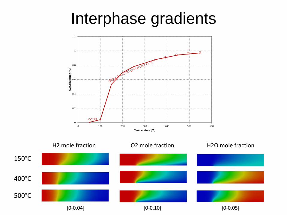
Interphase gradients
150°C
400°C
500°C
H2 mole fraction
[0-0.04] [0-0.10] [0-0.05]
O2 mole fraction H2O mole fraction
0
0,2
0,4
0,6
0,8
1
1,2
0 100 200 300 400 500 600
O2
Conv
ersi
on [%
]
Temperature [°C]

Outline
1) Effect of the distribution of the contact times in the reactor on the observed reaction rate
2) Inter-phase and intra-phase transport phenomena and their impact on the observed reaction rate
3) Show-case: effect of transport phenomena on catalyst reactivity
4) Take-home messages

Take-home messages 1) Physical transport may have a strong influence on the rate of the overall
process and may introduce additional dependences on the operating conditions
2) The observable reaction rate may differ substantially from the intrinsic rate of the chemical transformation under bulk fluid phase composition
A A A A A*
A* A*
A* 0
x
Chemical regime Internal mass transfer regime
Internal/External mass transfer
regime
Fully external mass transfer regime
TEMPERATURE

Take-home messages 1) Physical transport may have a strong influence on the rate of the overall
process and may introduce additional dependences on the operating conditions
2) The observable reaction rate may differ substantially from the intrinsic rate of the chemical transformation under bulk fluid phase composition
3) You need to be aware of such interplay and related effects in order to: 1) understand what you are measuring 2) understand what you are comparing 3) scale-up properly and successfully your reaction 4) force your catalyst to the desired observed functionality
(selectivity €€€!! – safe operation)
4) Reactivity measurement is intrinsically a multiscale phenomenon: make sure you minimize the effect of transport (dilution, temperature, geometry)

A first-principles approach to CRE
Time
Leng
th
MICROSCALE making and breaking of
chemical bonds
MESOSCALE Interplay among the
chemical events
MACROSCALE Reactor engineering and
transport phenomena CFD
Electronic structure theory
kMC

Thank you for your attention!
www.catalyticfoam.polimi.it
Politecnico di Milano Raffaello, The school of Athens, 1509, Apostolic Palace, Roma