Embed Size (px)
Citation preview
Computer-aided Drafting(SolidWorks)
Tutorial (Basics in SolidWorks)
小明 in ERB106
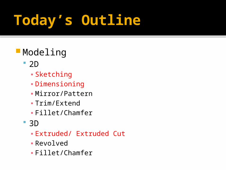
Today’s Outline
Modeling 2D▪ Sketching▪ Dimensioning▪ Mirror/Pattern▪ Trim/Extend▪ Fillet/Chamfer
3D▪ Extruded/ Extruded Cut▪ Revolved▪ Fillet/Chamfer
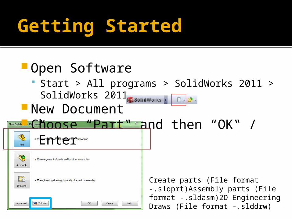
Getting Started
Open Software Start > All programs > SolidWorks 2011 >
SolidWorks 2011 New Document Choose “Part‟ and then “OK‟ /
”Enter”
Create parts (File format -.sldprt)Assembly parts (File format -.sldasm)2D Engineering Draws (File format -.slddrw)

Basic Interface
Drawing tools
Design tree
Drawing region
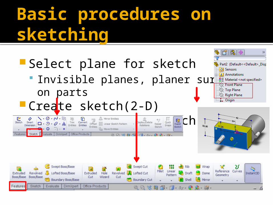
Basic procedures on sketching
Select plane for sketch Invisible planes, planer surface on parts
Create sketch(2-D) Draw features on sketch(3-D)
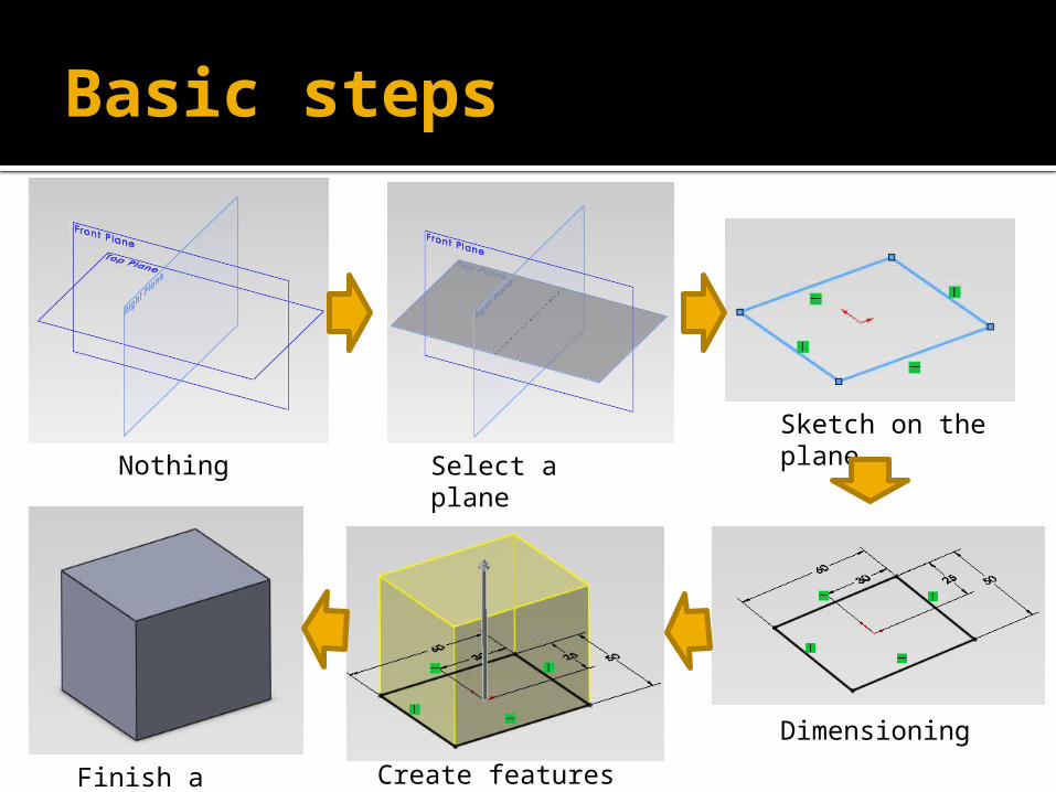
Basic steps
Sketch on the planeSelect a plane
Dimensioning
Create features (extrude)
Finish a feature
Nothing
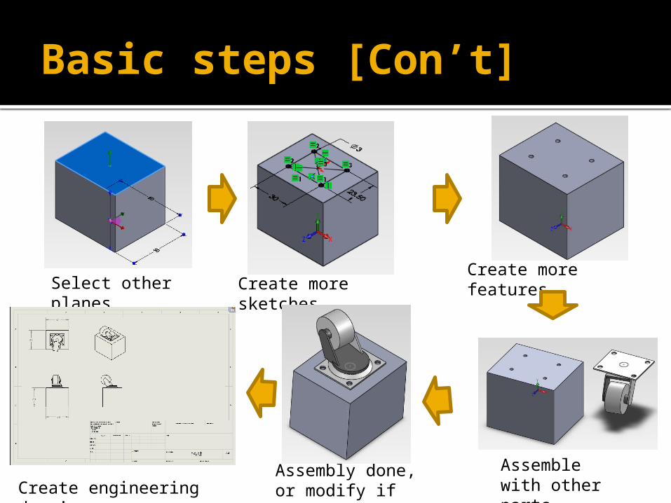
Basic steps [Con’t]
Create more featuresSelect other
planes
Assemble with other parts
Assembly done, or modify if necessary
Create more sketches
Create engineering drawing
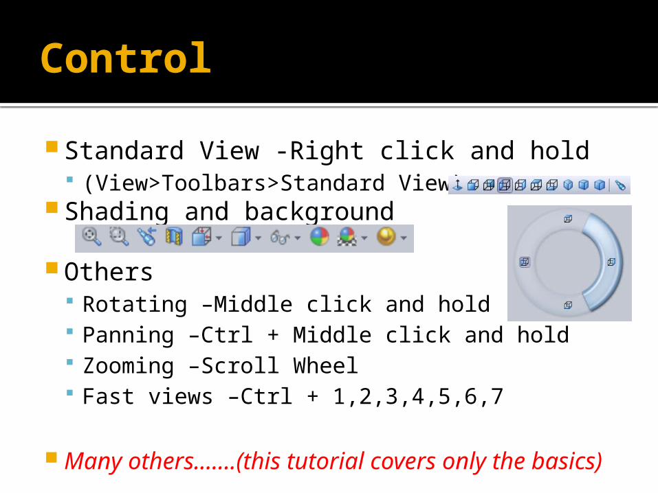
Control
Standard View -Right click and hold (View>Toolbars>Standard View)
Shading and background
Others Rotating –Middle click and hold Panning –Ctrl + Middle click and hold Zooming –Scroll Wheel Fast views –Ctrl + 1,2,3,4,5,6,7
Many others…….(this tutorial covers only the basics)
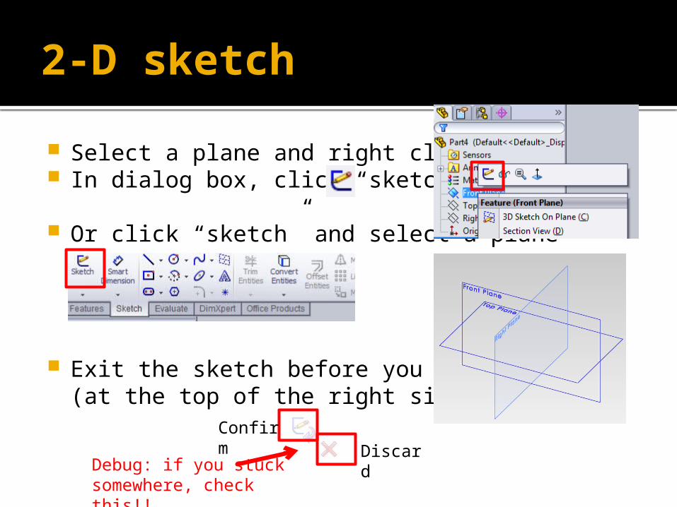
2-D sketch
Select a plane and right click. In dialog box, click “sketch”
Or click “sketch” and select a plane
Exit the sketch before you move on.(at the top of the right side)
Confirm Discard
Debug: if you stuck somewhere, check this!!
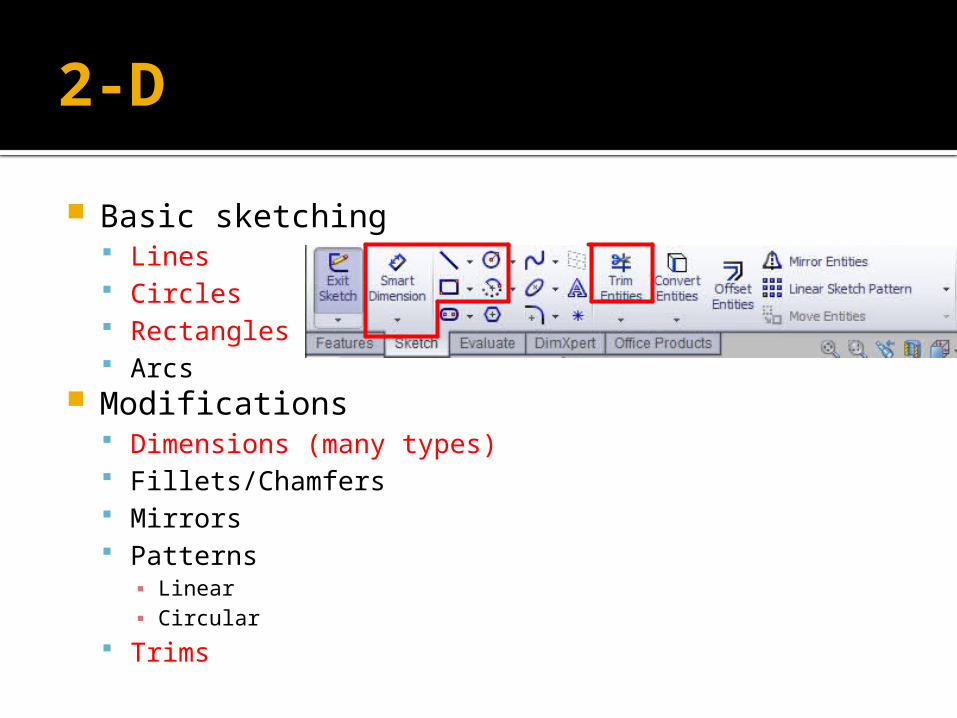
2-D
Basic sketching Lines Circles Rectangles Arcs
Modifications Dimensions (many types) Fillets/Chamfers Mirrors Patterns
▪ Linear▪ Circular
Trims
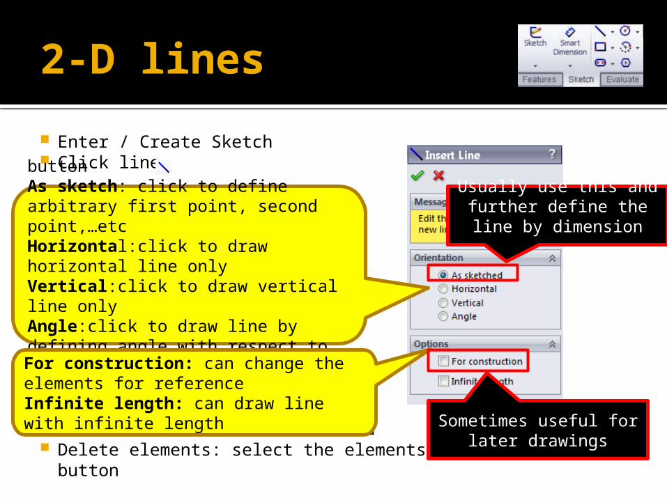
2-D lines
Enter / Create Sketch Click line
ESC : leave the current command Delete elements: select the elements and click delete button
buttonAs sketch: click to define arbitrary first point, second point,…etcHorizontal:click to draw horizontal line onlyVertical:click to draw vertical line onlyAngle:click to draw line by defining angle with respect to horizontal lineFor construction: can change the elements for referenceInfinite length: can draw line with infinite length
Usually use this and further define the line
by dimension
Sometimes useful for later drawings
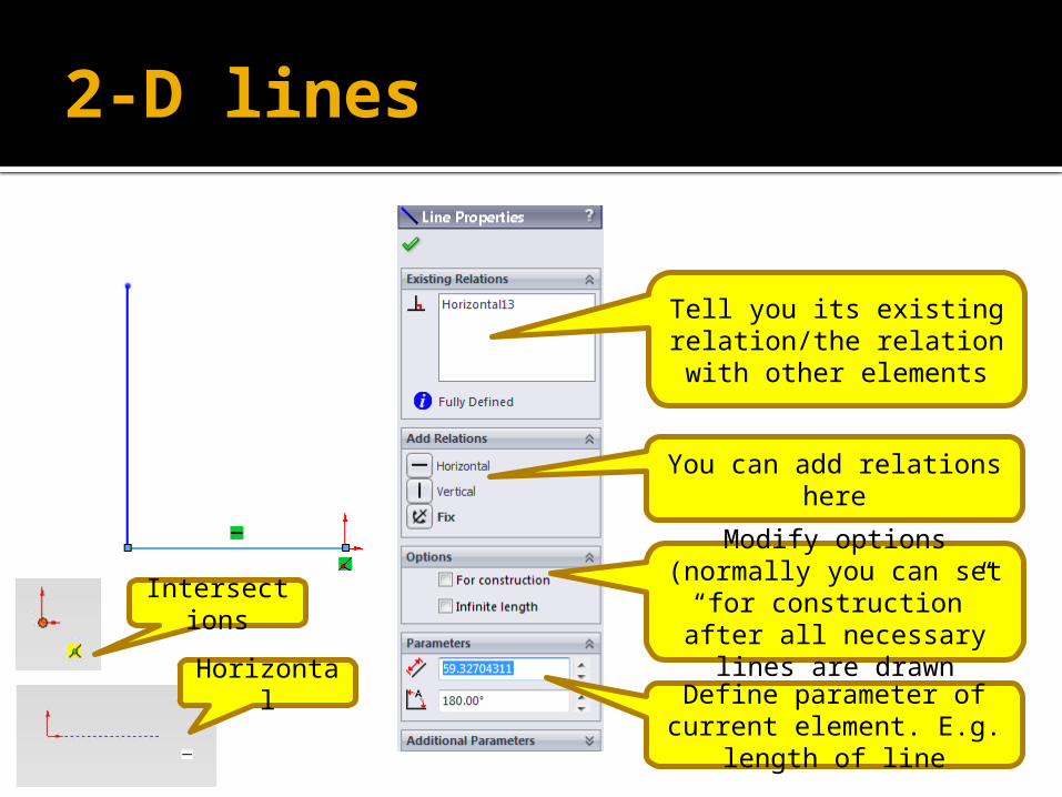
2-D lines
Tell you its existing relation/the relation with
other elements
You can add relations here
Modify options (normally you can set “for
construction” after all necessary lines are
drawnDefine parameter of current element. E.g.
length of line
Intersections
Horizontal
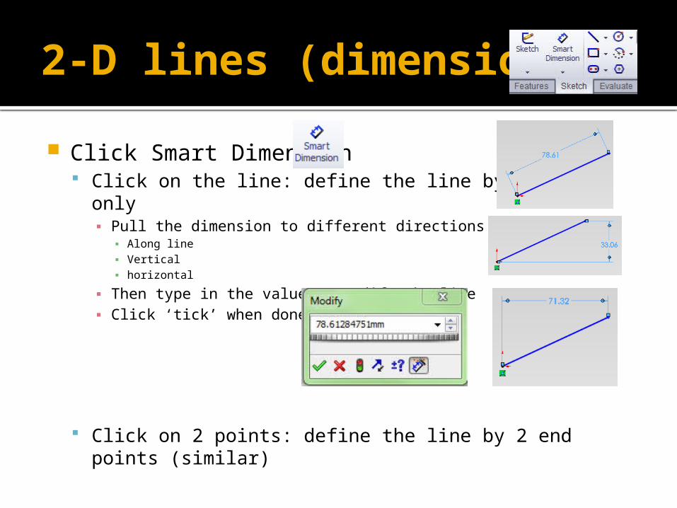
2-D lines (dimensions)
Click Smart Dimension Click on the line: define the line by length only
▪ Pull the dimension to different directions▪ Along line▪ Vertical ▪ horizontal
▪ Then type in the value to modify the line▪ Click ‘tick’ when done
Click on 2 points: define the line by 2 end points (similar)
2-D circles
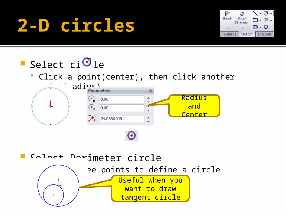
Select circle Click a point(center), then click another point(radius)
Select Perimeter circle Select three points to define a circle
Radius and Center
Useful when you want to draw tangent circle

2-D circles (dimensions)
Usually it is defined by its center and radiusNot yet fully defined
(blue) Fully defined (Black)
Or use the mouse to force set the relations of the center with some
reference (e.g. the origin)
2-D rectangles
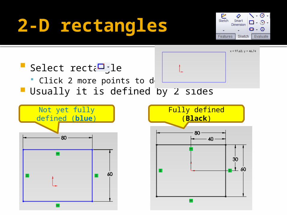
Select rectangle Click 2 more points to define it
Usually it is defined by 2 sides
Not yet fully defined (blue)
Fully defined (Black)

2-D Trim (cutting lines)
Click trim and select “trim to closest”
Trim the line between 2 (intersecting) points

2-D fillets / chamfers
Click fillet Fillet the corner at the intersection of two sketch (choose
a corner)
Click chamfer
Set corner radius

Extrude / extrude cut Revolve / revolve cut Fillets / chamfers Mirror Patterns
Linear Circular
Many others Loft base Sweep base Etc.
3-D
3-D extrudes
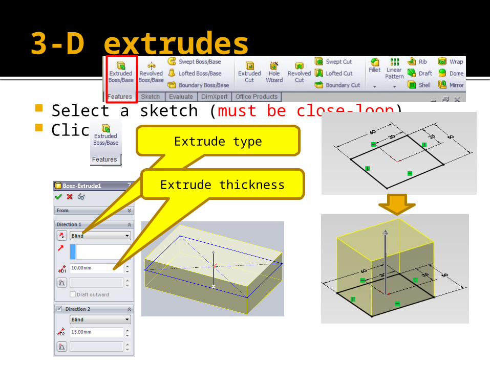
Select a sketch (must be close-loop) Click
Extrude type
Extrude thickness
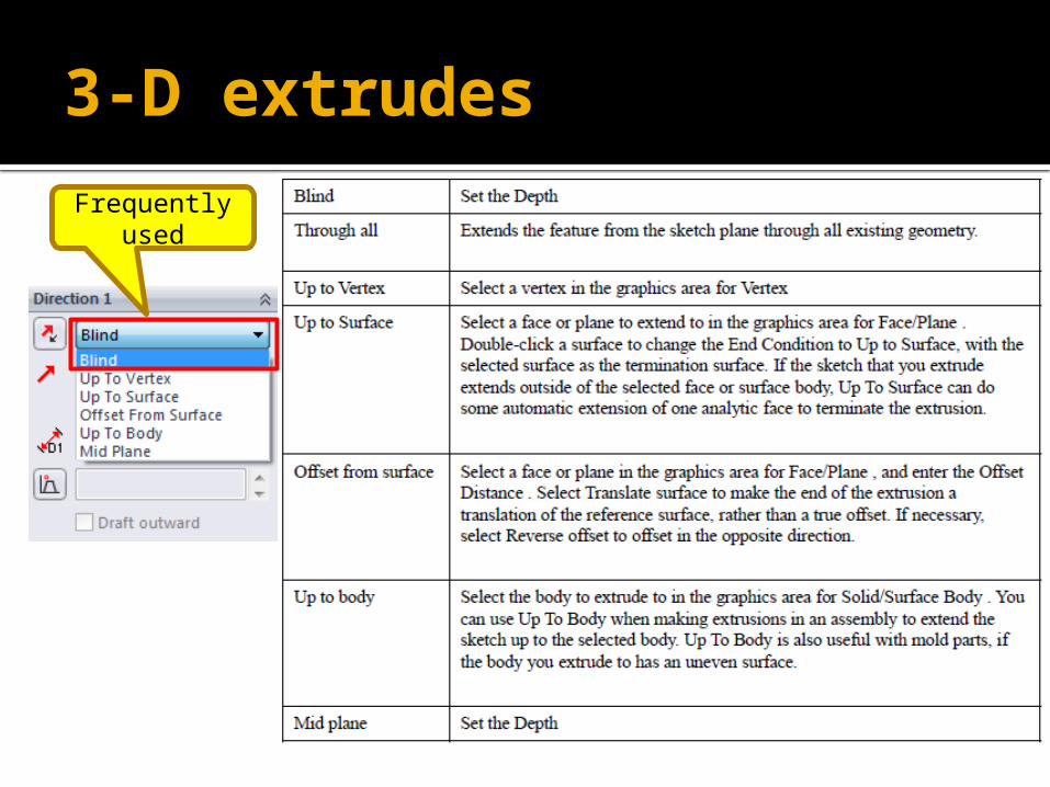
3-D extrudes
Frequently used
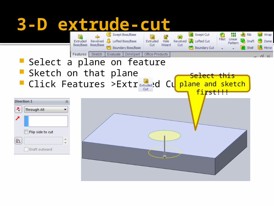
3-D extrude-cut
Select a plane on feature Sketch on that plane Click Features >Extruded Cut Select this plane
and sketch first!!!
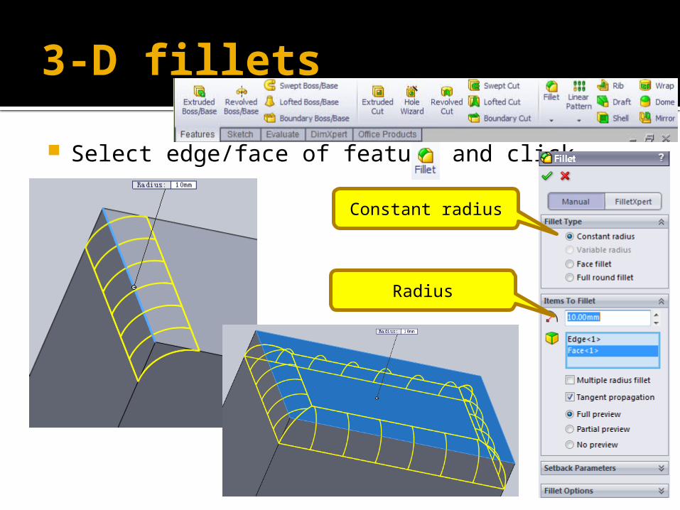
3-D fillets
Select edge/face of feature and click
Constant radius
Radius
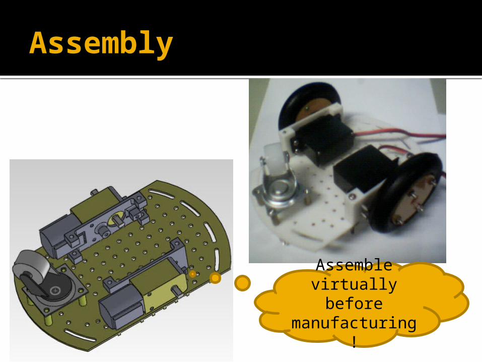
Assembly
Assemble virtually before manufacturing!
Assembly
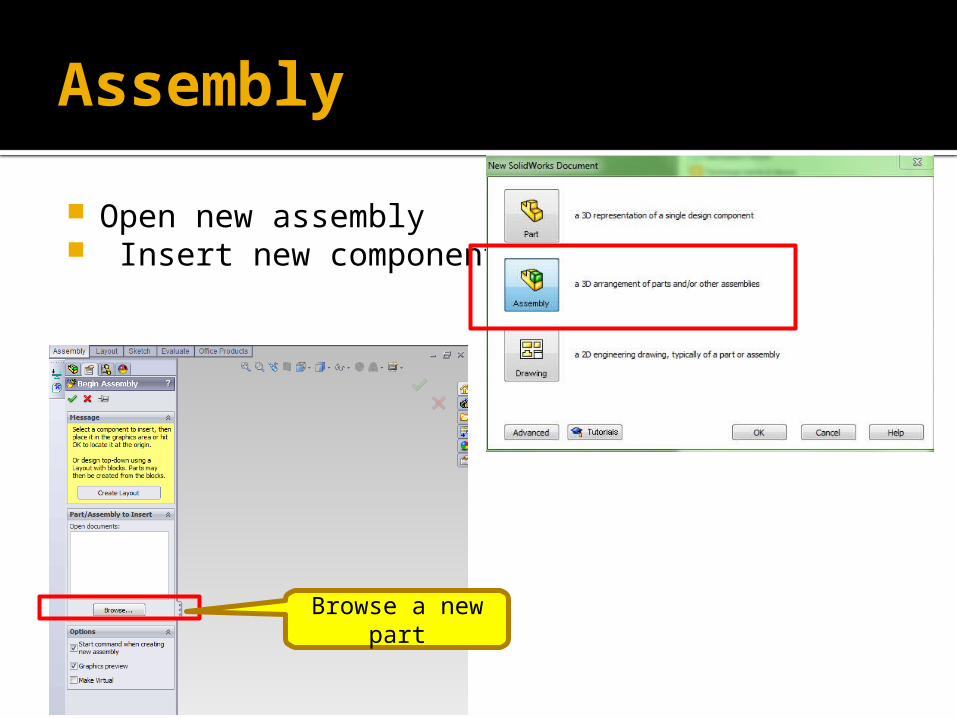
Open new assembly Insert new component
Browse a new part
Assembly
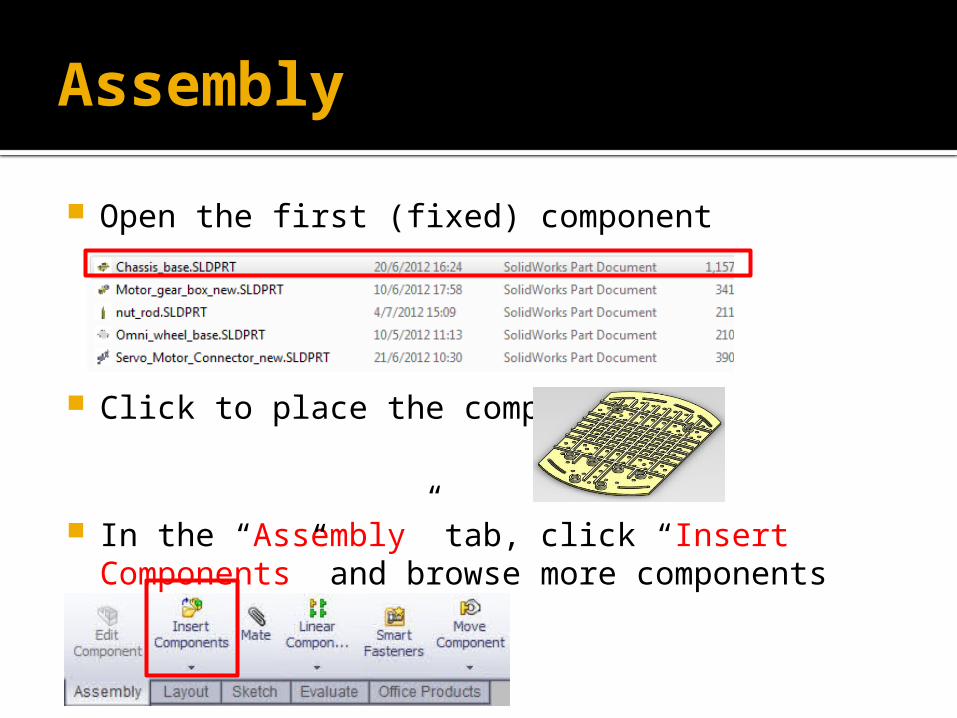
Open the first (fixed) component
Click to place the component
In the “Assembly” tab, click “Insert Components” and browse more components

Assembly
Take one part for each component (totally 5 more parts)
Duplicate parts: Press Ctrl + mouse (left) key on the motor (yellow part), pull away from it.

Assembly
The prefixes: (f) Fixed: position of this component is fixed, i.e., it CANNOT be moved / rotated. (-) Float: position of this component has NOT
been defined, i.e., it can be moved / rotated freely.
You can right-click it, and set to float if
necessary
Assembly
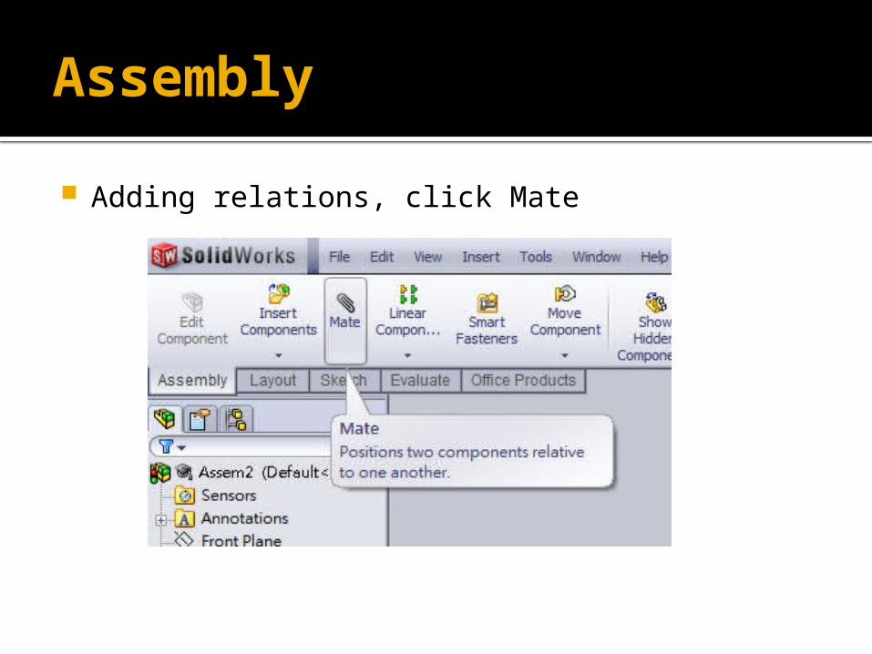
Adding relations, click Mate
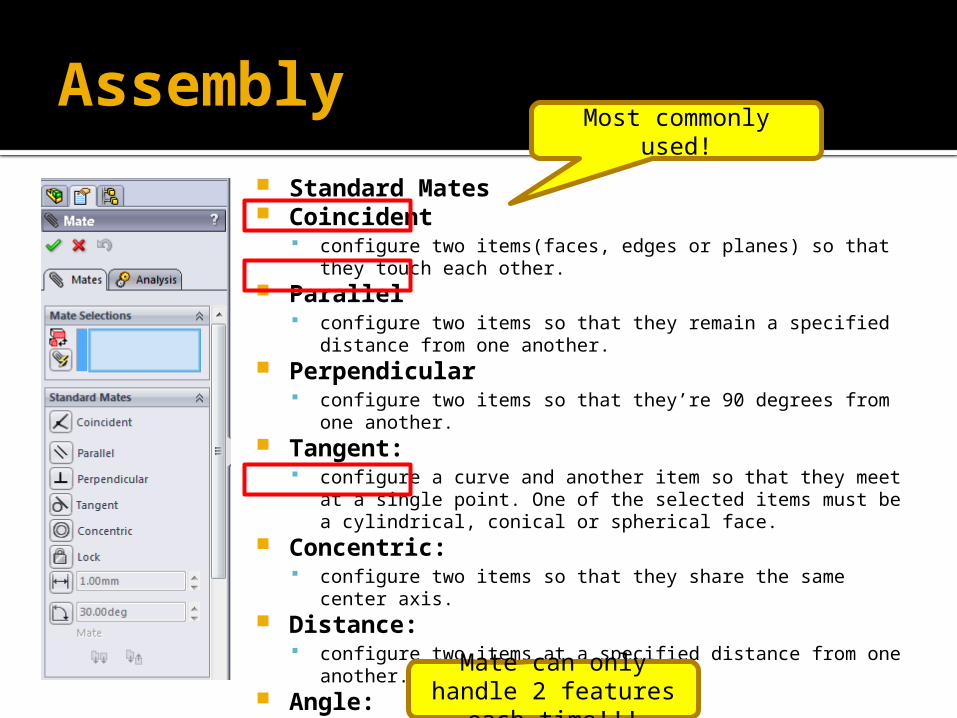
Assembly Standard Mates Coincident
configure two items(faces, edges or planes) so that they touch each other.
Parallel configure two items so that they remain a specified distance
from one another. Perpendicular
configure two items so that they’re 90 degrees from one another.
Tangent: configure a curve and another item so that they meet at a
single point. One of the selected items must be a cylindrical, conical or spherical face.
Concentric: configure two items so that they share the same center axis.
Distance: configure two items at a specified distance from one another.
Angle: configure two items at a specified angle to one another.
Most commonly used!
Mate can only handle 2 features each
time!!!

Assembly (omni-wheel)
Click “Mate”, select 2 faces
Assembly (omni-wheel)
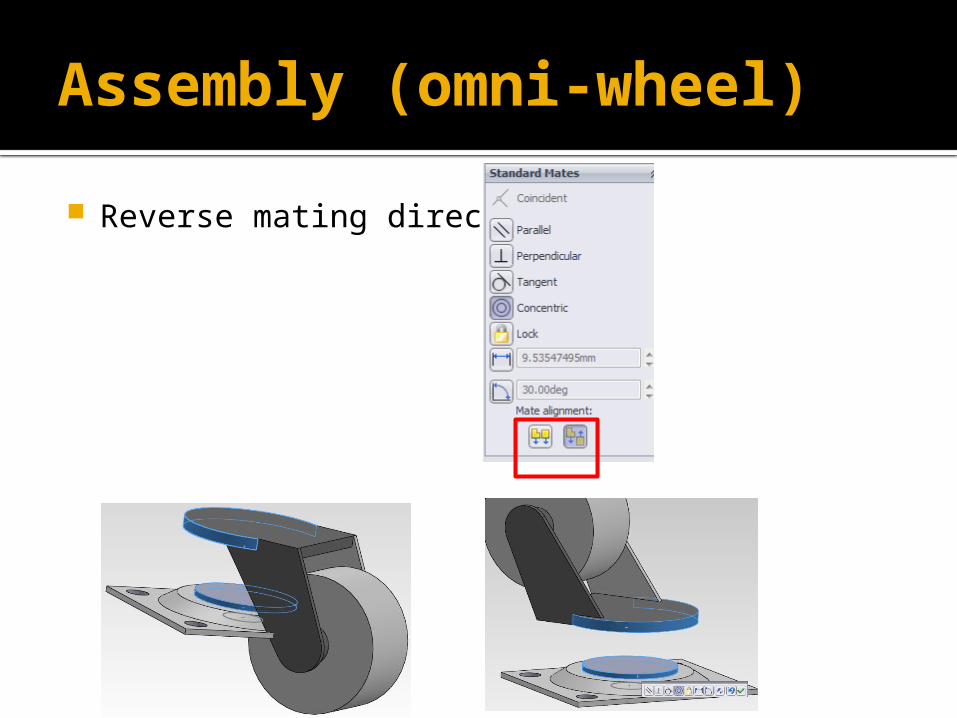
Reverse mating directions

Assembly (omni-wheel)
Mate (coincident), click 2 surfaces,then “Mate”, finally click “tick”
Assembly (screw rods)
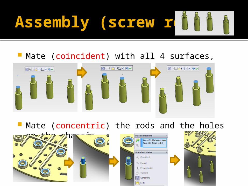
Mate (coincident) with all 4 surfaces,
Mate (concentric) the rods and the holes on the chassis,
Assembly (screw rods)
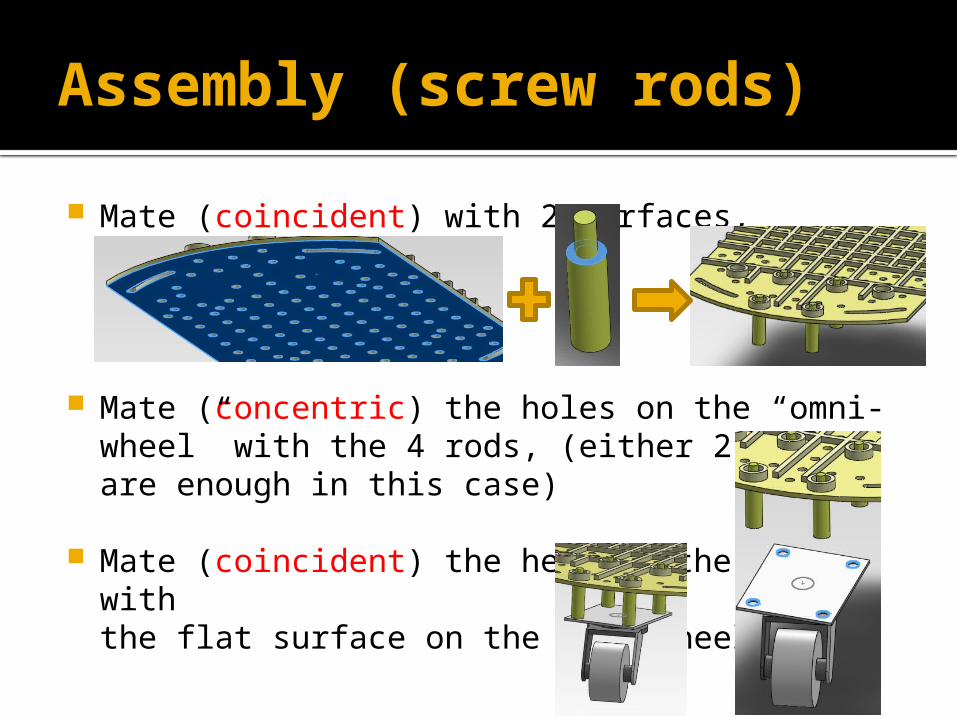
Mate (coincident) with 2 surfaces,
Mate (concentric) the holes on the “omni-wheel” with the 4 rods, (either 2 holes are enough in this case)
Mate (coincident) the head of the rods with the flat surface on the omni-wheel
Rapid Prototyping (RP)
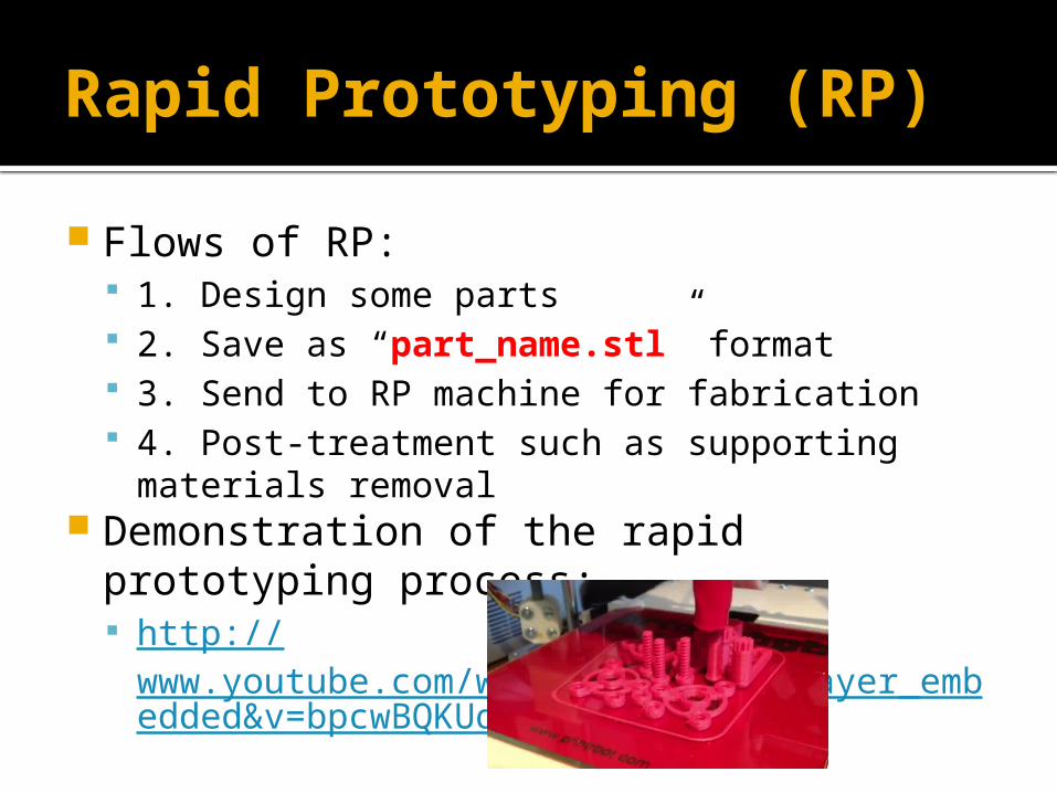
Flows of RP: 1. Design some parts 2. Save as “part_name.stl” format 3. Send to RP machine for fabrication 4. Post-treatment such as supporting materials
removal Demonstration of the rapid prototyping
process: http://
www.youtube.com/watch?feature=player_embedded&v=bpcwBQKUqK4

Thank you!Good luck with your
study!