Embed Size (px)
Citation preview
CIVL103, Civil Engineering Department, Faculty of Engineering
Eastern Mediterranean University, Spring 2013-2014
Tutorial 9:
CIVL103
1
Tutorial 9:
ENTRANCE
RECEPTION
ENTRANCE
RECEPTION
Fig 9.1: Reception Plan
CIVL103, Civil Engineering Department, Faculty of Engineering
Eastern Mediterranean University, Spring 2013-2014
Tutorial 9:
CIVL103
2
Introduction
In this tutorial you will draw the reception of a building. The dimensions of the drawing are
all in cm as seen in Fig 9.1. However you will draw these in mm as given in the following
guidelines.You can find the other details below.
DRAW THE FOLLOWING USING THE AUTOCAD COMMANDS
WALLS : RED
WALLS HATCH STYLE
ANSI 36
angle: 0
scale: 5
STAIRS: GREY
STAIRS HATCH STYLE:
HEX
angle: 45
scale: 5
TEXT:
ARİAL
height: 20
WINDOWS: CYAN (BRIGHT TURQUISE)
DIMENSIONS: BLUE
TABLES AND SEATS: MAGENTA (BRIGHT PINK, DRAWN AS BLOCKS)
BIG TREES: GREEN (DRAWN AS CIRCLE)
Starting the Drawing
To start the drawing, first you should decide the limits and units that you have to use.
Setting Limits and Units:
For X Limits
Left margin (3000)+Width of the first figure (10000)+ margin between the 2 figures (4000)+
Width of the second figure (10000) + right margin (3000)= 30000
CIVL103, Civil Engineering Department, Faculty of Engineering
Eastern Mediterranean University, Spring 2013-2014
Tutorial 9:
CIVL103
3
For Y limits:
Margin from the top (2500) + The total length (9500)+ + bottom margin (3000 mm)= 15000
You can arrange your limits as (30000, 15000)
Type:
Limits
0, 0
30000, 15000
Next you need to arrange the units. Select Format - Units, AutoCAD will display the
“Drawing Units” dialog box. Make sure Decimal is selected in the Length section and
Decimal Degrees in the Angles section, then in Unit’s Precision, click on the down arrow
beside “0.0000”, and finally select “OK”.
At this point the screen is still displaying the old 420 X 297 size and we need to magnify the
screen to the new size. This is done by typing:
Command: ZOOM
Specify corner of window, enter a scale factor (nX or nXP), or
[All/Center/Dynamic/Extents/Previous/Scale/Window/Object] <real time>: A
Regenerating model.
Alternatively you can select zoom all icon from the zoom toolbar.
Rulers, grids and snapping
Click on Tools Menu
Click on Drafting Settings
In the SNAP section enter 100 in the X spacing box
(The Y spacing changes automatically to 100 by highlighting the Y box)
Check the ON box
Click on OK, arrange the grids to 100 as well.
CIVL103, Civil Engineering Department, Faculty of Engineering
Eastern Mediterranean University, Spring 2013-2014
Tutorial 9:
CIVL103
4
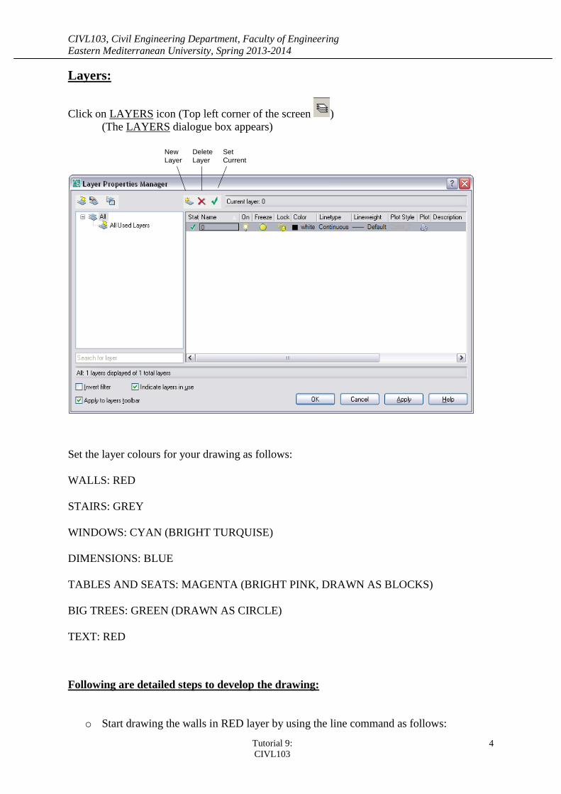
Layers:
Click on LAYERS icon (Top left corner of the screen )
(The LAYERS dialogue box appears)
New
Layer
Set
Current
Delete
Layer
Set the layer colours for your drawing as follows:
WALLS: RED
STAIRS: GREY
WINDOWS: CYAN (BRIGHT TURQUISE)
DIMENSIONS: BLUE
TABLES AND SEATS: MAGENTA (BRIGHT PINK, DRAWN AS BLOCKS)
BIG TREES: GREEN (DRAWN AS CIRCLE)
TEXT: RED
Following are detailed steps to develop the drawing:
o Start drawing the walls in RED layer by using the line command as follows:
CIVL103, Civil Engineering Department, Faculty of Engineering
Eastern Mediterranean University, Spring 2013-2014
Tutorial 9:
CIVL103
5
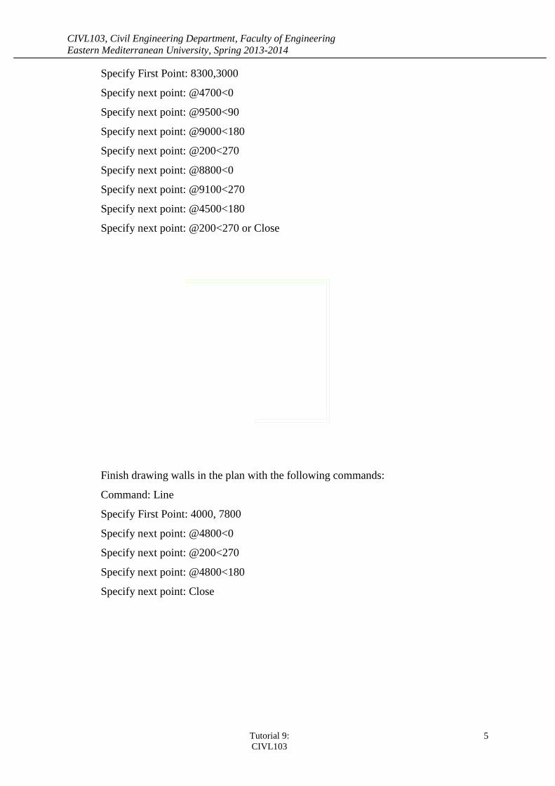
Specify First Point: 8300,3000
Specify next point: @4700<0
Specify next point: @9500<90
Specify next point: @9000<180
Specify next point: @200<270
Specify next point: @8800<0
Specify next point: @9100<270
Specify next point: @4500<180
Specify next point: @200<270 or Close
Finish drawing walls in the plan with the following commands:
Command: Line
Specify First Point: 4000, 7800
Specify next point: @4800<0
Specify next point: @200<270
Specify next point: @4800<180
Specify next point: Close
CIVL103, Civil Engineering Department, Faculty of Engineering
Eastern Mediterranean University, Spring 2013-2014
Tutorial 9:
CIVL103
6
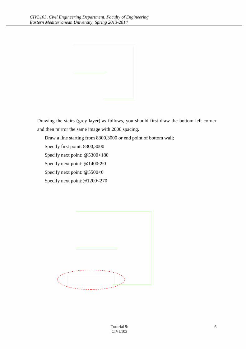
Drawing the stairs (grey layer) as follows, you should first draw the bottom left corner
and then mirror the same image with 2000 spacing.
Draw a line starting from 8300,3000 or end point of bottom wall;
Specify first point: 8300,3000
Specify next point: @5300<180
Specify next point: @1400<90
Specify next point: @5500<0
Specify next point:@1200<270
CIVL103, Civil Engineering Department, Faculty of Engineering
Eastern Mediterranean University, Spring 2013-2014
Tutorial 9:
CIVL103
7
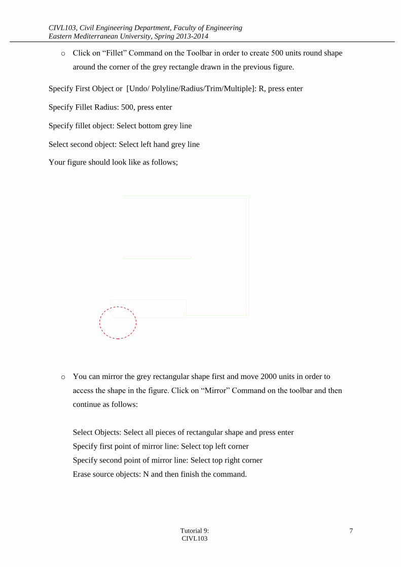
o Click on “Fillet” Command on the Toolbar in order to create 500 units round shape
around the corner of the grey rectangle drawn in the previous figure.
Specify First Object or [Undo/ Polyline/Radius/Trim/Multiple]: R, press enter
Specify Fillet Radius: 500, press enter
Specify fillet object: Select bottom grey line
Select second object: Select left hand grey line
Your figure should look like as follows;
o You can mirror the grey rectangular shape first and move 2000 units in order to
access the shape in the figure. Click on “Mirror” Command on the toolbar and then
continue as follows:
Select Objects: Select all pieces of rectangular shape and press enter
Specify first point of mirror line: Select top left corner
Specify second point of mirror line: Select top right corner
Erase source objects: N and then finish the command.
CIVL103, Civil Engineering Department, Faculty of Engineering
Eastern Mediterranean University, Spring 2013-2014
Tutorial 9:
CIVL103
8
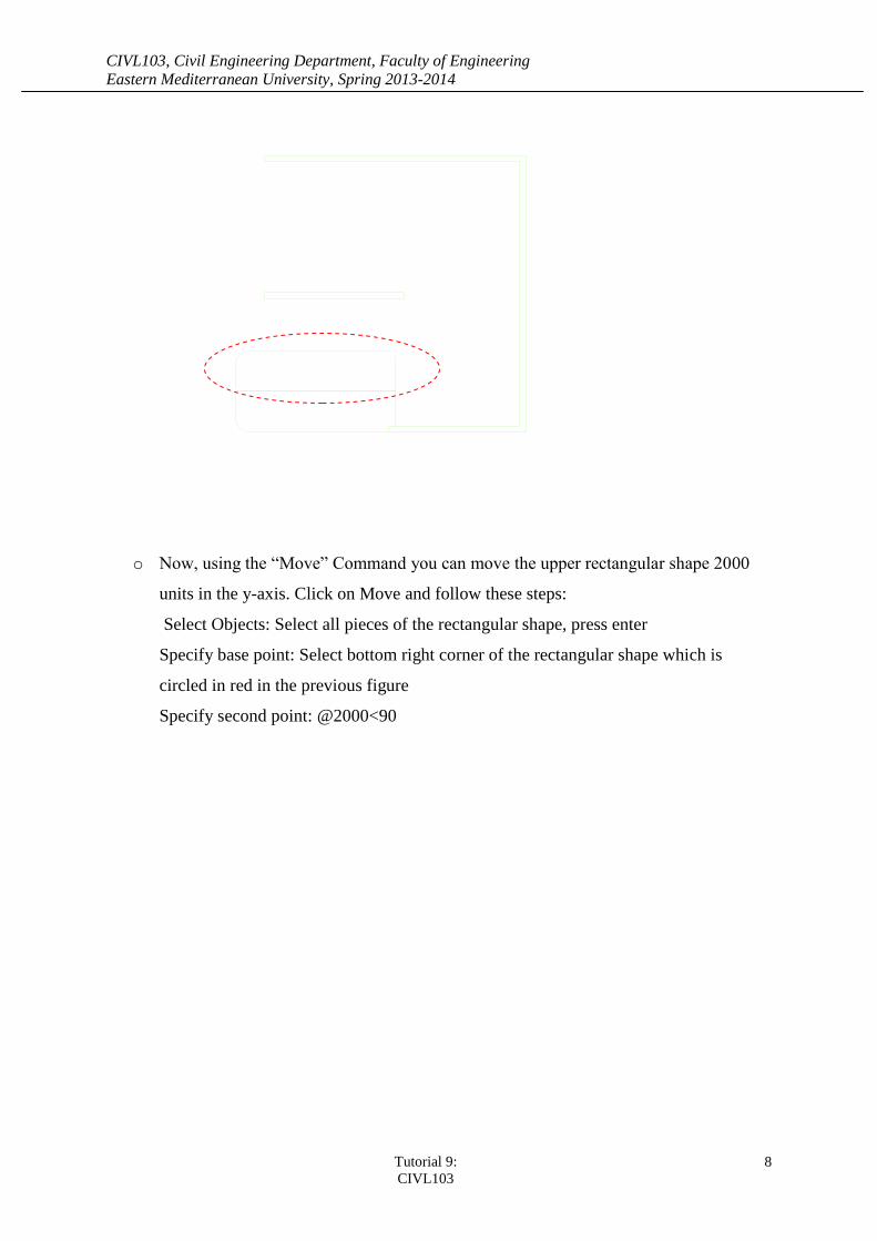
o Now, using the “Move” Command you can move the upper rectangular shape 2000
units in the y-axis. Click on Move and follow these steps:
Select Objects: Select all pieces of the rectangular shape, press enter
Specify base point: Select bottom right corner of the rectangular shape which is
circled in red in the previous figure
Specify second point: @2000<90
CIVL103, Civil Engineering Department, Faculty of Engineering
Eastern Mediterranean University, Spring 2013-2014
Tutorial 9:
CIVL103
9
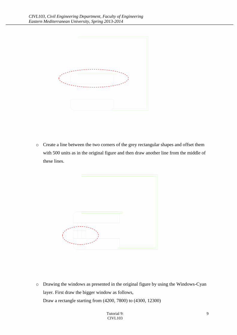
o Create a line between the two corners of the grey rectangular shapes and offset them
with 500 units as in the original figure and then draw another line from the middle of
these lines.
o Drawing the windows as presented in the original figure by using the Windows-Cyan
layer. First draw the bigger window as follows,
Draw a rectangle starting from (4200, 7800) to (4300, 12300)
CIVL103, Civil Engineering Department, Faculty of Engineering
Eastern Mediterranean University, Spring 2013-2014
Tutorial 9:
CIVL103
10
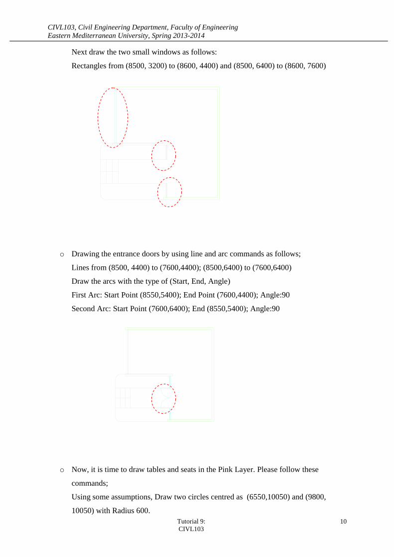
Next draw the two small windows as follows:
Rectangles from (8500, 3200) to (8600, 4400) and (8500, 6400) to (8600, 7600)
o Drawing the entrance doors by using line and arc commands as follows;
Lines from (8500, 4400) to (7600,4400); (8500,6400) to (7600,6400)
Draw the arcs with the type of (Start, End, Angle)
First Arc: Start Point (8550,5400); End Point (7600,4400); Angle:90
Second Arc: Start Point (7600,6400); End (8550,5400); Angle:90
o Now, it is time to draw tables and seats in the Pink Layer. Please follow these
commands;
Using some assumptions, Draw two circles centred as (6550,10050) and (9800,
10050) with Radius 600.
CIVL103, Civil Engineering Department, Faculty of Engineering
Eastern Mediterranean University, Spring 2013-2014
Tutorial 9:
CIVL103
11
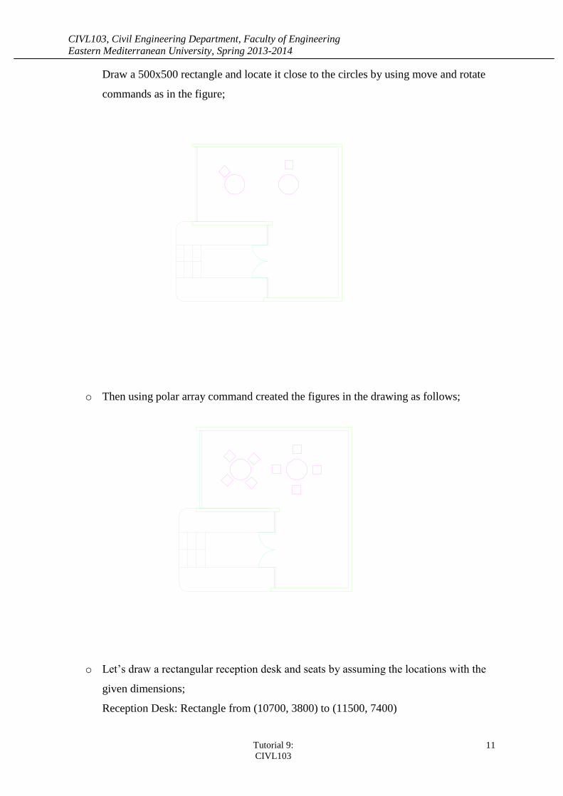
Draw a 500x500 rectangle and locate it close to the circles by using move and rotate
commands as in the figure;
o Then using polar array command created the figures in the drawing as follows;
o Let’s draw a rectangular reception desk and seats by assuming the locations with the
given dimensions;
Reception Desk: Rectangle from (10700, 3800) to (11500, 7400)
CIVL103, Civil Engineering Department, Faculty of Engineering
Eastern Mediterranean University, Spring 2013-2014
Tutorial 9:
CIVL103
12
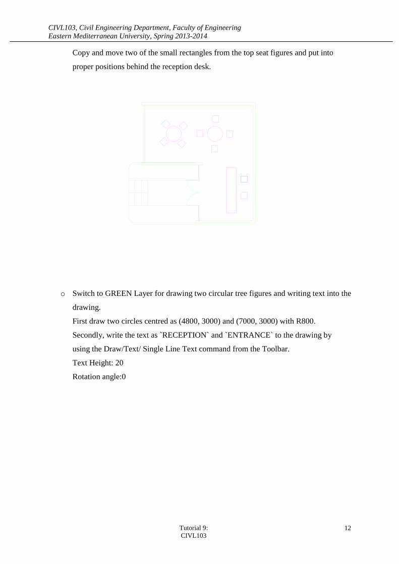
Copy and move two of the small rectangles from the top seat figures and put into
proper positions behind the reception desk.
o Switch to GREEN Layer for drawing two circular tree figures and writing text into the
drawing.
First draw two circles centred as (4800, 3000) and (7000, 3000) with R800.
Secondly, write the text as `RECEPTION` and `ENTRANCE` to the drawing by
using the Draw/Text/ Single Line Text command from the Toolbar.
Text Height: 20
Rotation angle:0
CIVL103, Civil Engineering Department, Faculty of Engineering
Eastern Mediterranean University, Spring 2013-2014
Tutorial 9:
CIVL103
13
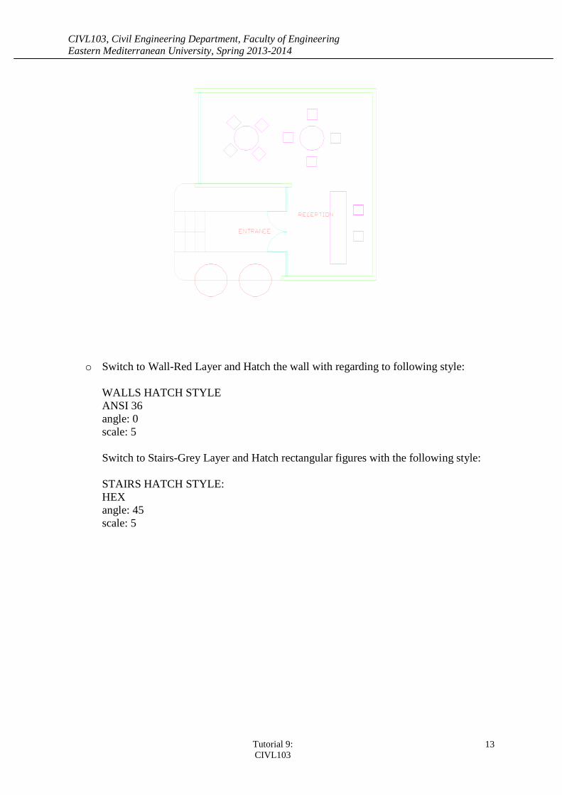
o Switch to Wall-Red Layer and Hatch the wall with regarding to following style:
WALLS HATCH STYLE
ANSI 36
angle: 0
scale: 5
Switch to Stairs-Grey Layer and Hatch rectangular figures with the following style:
STAIRS HATCH STYLE:
HEX
angle: 45
scale: 5
CIVL103, Civil Engineering Department, Faculty of Engineering
Eastern Mediterranean University, Spring 2013-2014
Tutorial 9:
CIVL103
14
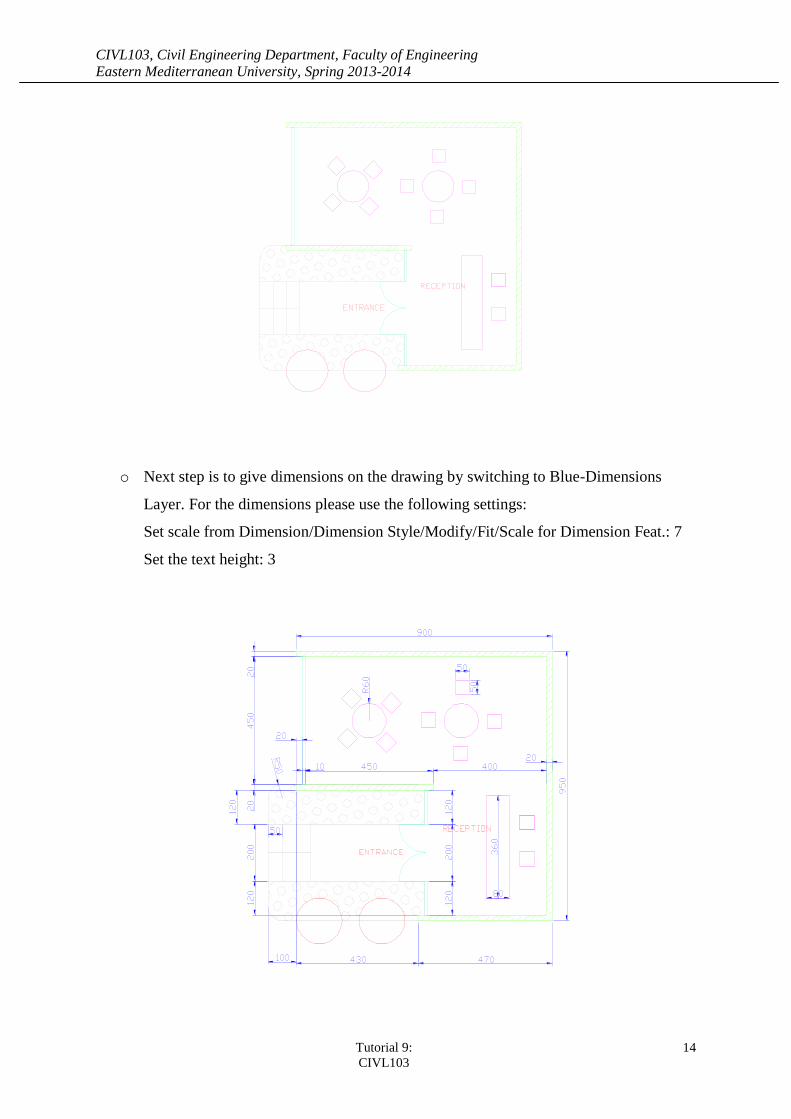
o Next step is to give dimensions on the drawing by switching to Blue-Dimensions
Layer. For the dimensions please use the following settings:
Set scale from Dimension/Dimension Style/Modify/Fit/Scale for Dimension Feat.: 7
Set the text height: 3
CIVL103, Civil Engineering Department, Faculty of Engineering
Eastern Mediterranean University, Spring 2013-2014
Tutorial 9:
CIVL103
15
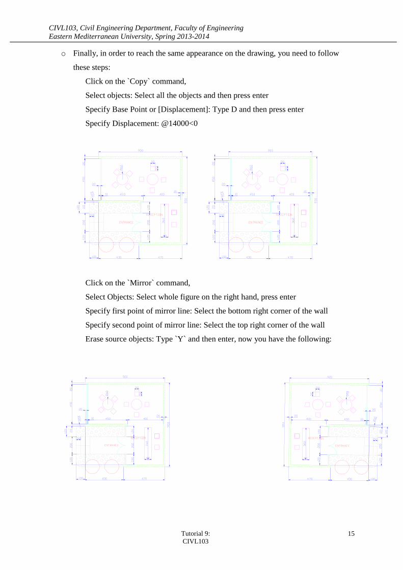
o Finally, in order to reach the same appearance on the drawing, you need to follow
these steps:
Click on the `Copy` command,
Select objects: Select all the objects and then press enter
Specify Base Point or [Displacement]: Type D and then press enter
Specify Displacement: @14000<0
Click on the `Mirror` command,
Select Objects: Select whole figure on the right hand, press enter
Specify first point of mirror line: Select the bottom right corner of the wall
Specify second point of mirror line: Select the top right corner of the wall
Erase source objects: Type `Y` and then enter, now you have the following:
CIVL103, Civil Engineering Department, Faculty of Engineering
Eastern Mediterranean University, Spring 2013-2014
Tutorial 9:
CIVL103
16
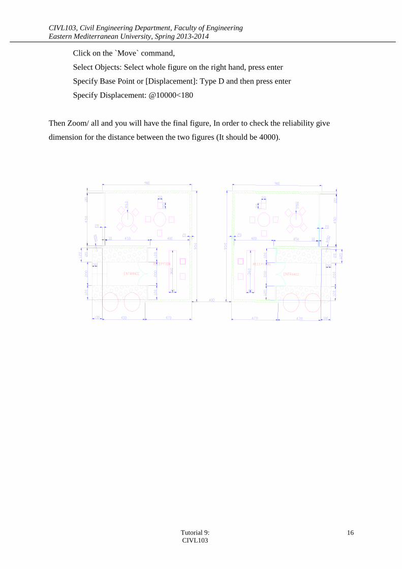
Click on the `Move` command,
Select Objects: Select whole figure on the right hand, press enter
Specify Base Point or [Displacement]: Type D and then press enter
Specify Displacement: @10000<180
Then Zoom/ all and you will have the final figure, In order to check the reliability give
dimension for the distance between the two figures (It should be 4000).