Embed Size (px)
Citation preview
Tutorial 18: Handles
Copyright © 1995-2015 Esri. All rights reserved.
Table of ContentsTutorial 18: Handles . . . . . . . . . . . . . . . . . . . . . . . . . . . . . . . . . . . . . . . . . . . . 3
Tutorial 18: Handles
Copyright © 1995-2015 Esri. All rights reserved. 2
Tutorial 18: HandlesIn this tutorial:
• Part 1: Basic Linear Handles
• Part 2: Advanced Linear Handles
• Part 3: Other Types of Handles
Download:
• Tutorial data
• Tutorial pdf
Prerequisites
• CityEngine 2015.0 or later
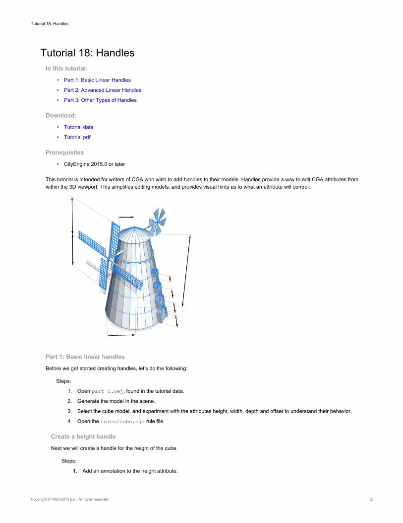
This tutorial is intended for writers of CGA who wish to add handles to their models. Handles provide a way to edit CGA attributes fromwithin the 3D viewport. This simplifies editing models, and provides visual hints as to what an attribute will control.
Part 1: Basic linear handles
Before we get started creating handles, let's do the following:
Steps:
1. Open part 1.cej, found in the tutorial data.
2. Generate the model in the scene.
3. Select the cube model, and experiment with the attributes height, width, depth and offset to understand their behavior.
4. Open the rules/cube.cga rule file.
Create a height handle
Next we will create a handle for the height of the cube.
Steps:
1. Add an annotation to the height attribute:
Tutorial 18: Handles
Copyright © 1995-2015 Esri. All rights reserved. 3
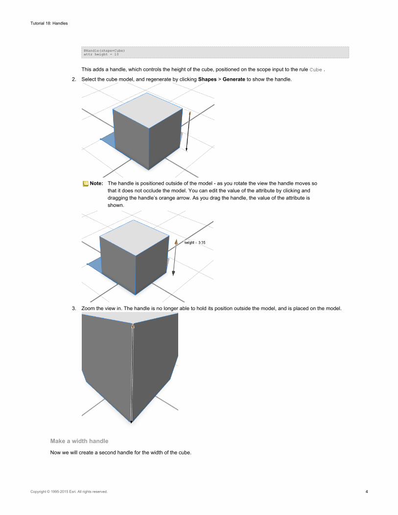
@Handle(shape=Cube)attr height = 10
This adds a handle, which controls the height of the cube, positioned on the scope input to the rule Cube .
2. Select the cube model, and regenerate by clicking Shapes > Generate to show the handle.
Note: The handle is positioned outside of the model - as you rotate the view the handle moves sothat it does not occlude the model. You can edit the value of the attribute by clicking anddragging the handle’s orange arrow. As you drag the handle, the value of the attribute isshown.
3. Zoom the view in. The handle is no longer able to hold its position outside the model, and is placed on the model.
Make a width handle
Now we will create a second handle for the width of the cube.
Tutorial 18: Handles
Copyright © 1995-2015 Esri. All rights reserved. 4
Steps:
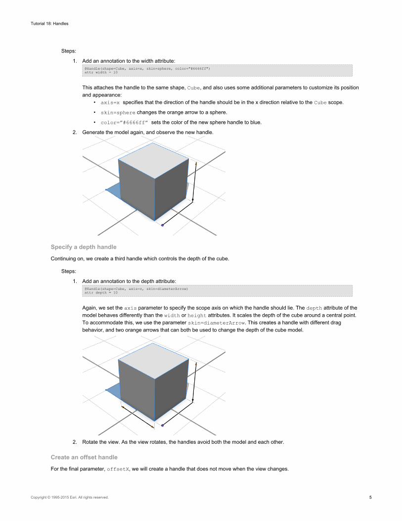
1. Add an annotation to the width attribute:@Handle(shape=Cube, axis=x, skin=sphere, color="#6666ff")attr width = 10
This attaches the handle to the same shape, Cube, and also uses some additional parameters to customize its positionand appearance:
• axis=x specifies that the direction of the handle should be in the x direction relative to the Cube scope.
• skin=sphere changes the orange arrow to a sphere.
• color=”#6666ff” sets the color of the new sphere handle to blue.
2. Generate the model again, and observe the new handle.
Specify a depth handle
Continuing on, we create a third handle which controls the depth of the cube.
Steps:
1. Add an annotation to the depth attribute:@Handle(shape=Cube, axis=z, skin=diameterArrow)attr depth = 10
Again, we set the axis parameter to specify the scope axis on which the handle should lie. The depth attribute of themodel behaves differently than the width or height attributes. It scales the depth of the cube around a central point.To accommodate this, we use the parameter skin=diameterArrow. This creates a handle with different dragbehavior, and two orange arrows that can both be used to change the depth of the cube model.
2. Rotate the view. As the view rotates, the handles avoid both the model and each other.
Create an offset handle
For the final parameter, offsetX, we will create a handle that does not move when the view changes.
Tutorial 18: Handles
Copyright © 1995-2015 Esri. All rights reserved. 5
Steps:
1. Add the following annotation:@Handle(shape=ShapeForHandleOnly, axis=x, reference=origin, slip=inside)attr offsetX = 5
We attached this handle to a “dummy” scope that was created just for this handle. The parameter slip=insiderequests that the handle lies inside the model silhouette, and not move with the viewpoint. Normally a handle mayappear on any four of the scope’s edges in the given axis direction; however reference=origin causes the handle toonly appear on the edge adjacent to the scope’s origin.
Note: The rule ShapeForHandleOnly produces nogeometry.
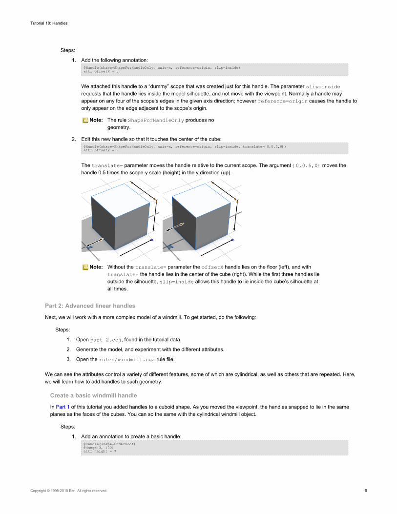
2. Edit this new handle so that it touches the center of the cube:@Handle(shape=ShapeForHandleOnly, axis=x, reference=origin, slip=inside, translate={0,0.5,0})attr offsetX = 5
The translate= parameter moves the handle relative to the current scope. The argument {0,0.5,0} moves thehandle 0.5 times the scope-y scale (height) in the y direction (up).
Note: Without the translate= parameter the offsetX handle lies on the floor (left), and withtranslate= the handle lies in the center of the cube (right). While the first three handles lieoutside the silhouette, slip=inside allows this handle to lie inside the cube’s silhouette atall times.
Part 2: Advanced linear handles
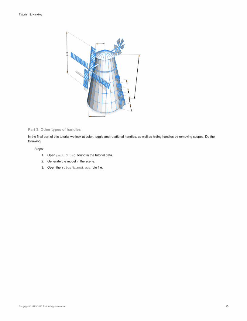
Next, we will work with a more complex model of a windmill. To get started, do the following:
Steps:
1. Open part 2.cej, found in the tutorial data.
2. Generate the model, and experiment with the different attributes.
3. Open the rules/windmill.cga rule file.
We can see the attributes control a variety of different features, some of which are cylindrical, as well as others that are repeated. Here,we will learn how to add handles to such geometry.
Create a basic windmill handle
In Part 1 of this tutorial you added handles to a cuboid shape. As you moved the viewpoint, the handles snapped to lie in the sameplanes as the faces of the cubes. You can so the same with the cylindrical windmill object.
Steps:
1. Add an annotation to create a basic handle:@Handle(shape=UnderRoof)@Range(3, 100)attr height = 7
Tutorial 18: Handles
Copyright © 1995-2015 Esri. All rights reserved. 6
As we rotate the view, we notice that this handle isn’t very effective. As the view rotates, it jumps between positions atthe corners of the UnderRoof scope. Because the scope is larger and a different shape than the building, it difficult tofollow the association between the model and the handle.
2. Edit the annotation to create an effective handle for the windmill.@Handle(shape=UnderRoof, reference=center, slip=screen)@Range(3, 100)attr height = 7
Here, the parameter reference=center attaches the handle to the center of the scope (see the CGA documentationfor details of the other reference-positions available). slip= defines the direction in which the handle is moved outsidethe model. In this case slip=screen specifies that it moves parallel to itself over the 2D screen. The resulting handlemovement is much smoother and clearer.
Add radius handles
We can continue to add two handles controlling the radius of the windmill at the top and bottom of the screen.
Steps:
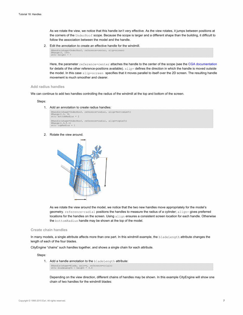
1. Add an annotation to create radius handles:@Handle(shape=UnderRoof, reference=radial, align=bottomLeft)@Range(1.5, 9)attr bottomRadius = 2@Handle(shape=UnderRoof, reference=radial, align=topLeft)@Range(1.0,5.1)attr topRadius = 1
2. Rotate the view around.
As we rotate the view around the model, we notice that the two new handles move appropriately for the model’sgeometry. reference=radial positions the handles to measure the radius of a cylinder; align= gives preferredlocations for the handles on the screen. Using align ensures a consistent screen location for each handle. Otherwisethe bottomRadius handle may be shown at the top of the model.
Create chain handles
In many models, a single attribute affects more than one part. In this windmill example, the bladeLength attribute changes thelength of each of the four blades.
CityEngine “chains” such handles together, and shows a single chain for each attribute.
Steps:
1. Add a handle annotation to the bladeLength attribute:@Handle(shape=Blade, axis=x, reference=origin)attr bladeLength = height * 0.6
Depending on the view direction, different chains of handles may be shown. In this example CityEngine will show onechain of two handles for the windmill blades:
Tutorial 18: Handles
Copyright © 1995-2015 Esri. All rights reserved. 7
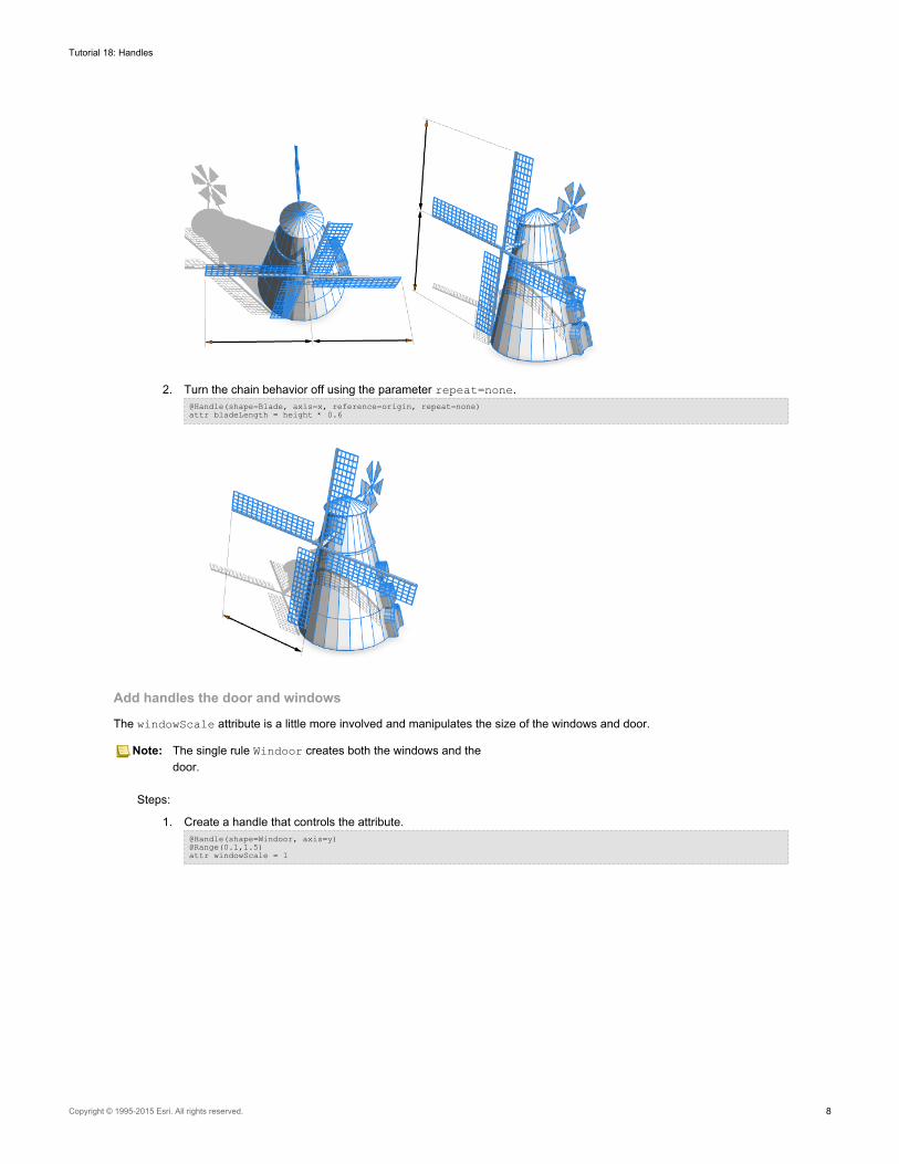
2. Turn the chain behavior off using the parameter repeat=none.@Handle(shape=Blade, axis=x, reference=origin, repeat=none)attr bladeLength = height * 0.6
Add handles the door and windows
The windowScale attribute is a little more involved and manipulates the size of the windows and door.
Note: The single rule Windoor creates both the windows and thedoor.
Steps:
1. Create a handle that controls the attribute.@Handle(shape=Windoor, axis=y)@Range(0.1,1.5)attr windowScale = 1
Tutorial 18: Handles
Copyright © 1995-2015 Esri. All rights reserved. 8
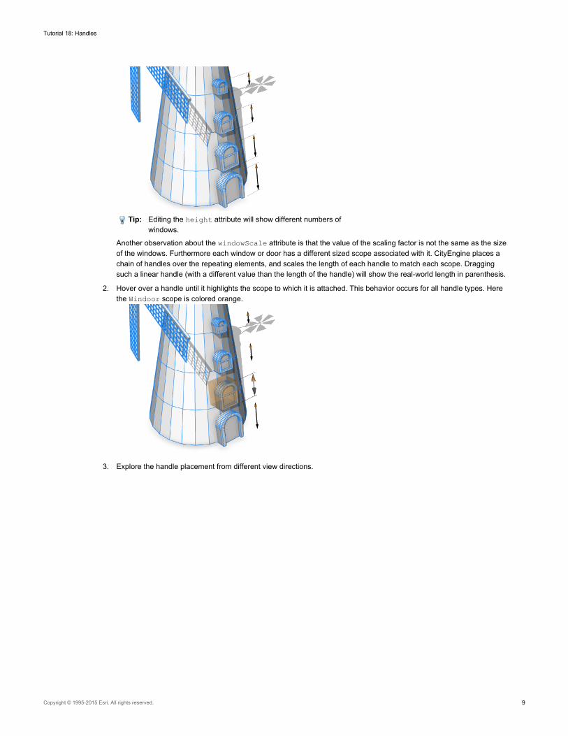
Tip: Editing the height attribute will show different numbers ofwindows.
Another observation about the windowScale attribute is that the value of the scaling factor is not the same as the sizeof the windows. Furthermore each window or door has a different sized scope associated with it. CityEngine places achain of handles over the repeating elements, and scales the length of each handle to match each scope. Draggingsuch a linear handle (with a different value than the length of the handle) will show the real-world length in parenthesis.
2. Hover over a handle until it highlights the scope to which it is attached. This behavior occurs for all handle types. Herethe Windoor scope is colored orange.
3. Explore the handle placement from different view directions.
Tutorial 18: Handles
Copyright © 1995-2015 Esri. All rights reserved. 9
Part 3: Other types of handles
In the final part of this tutorial we look at color, toggle and rotational handles, as well as hiding handles by removing scopes. Do thefollowing:
Steps:
1. Open part 3.cej, found in the tutorial data.
2. Generate the model in the scene.
3. Open the rules/biped.cga rule file.
Tutorial 18: Handles
Copyright © 1995-2015 Esri. All rights reserved. 10
In Part 1 and Part 2, of this tutorial we used linear handles. In addition to these types, handles can control other types of attributes. Let’sadd a color handle that sits above the head of our model.
Add a scope to model
When working with unfamiliar CGA code, it is often useful to use the Model Hierarchy to explore the available scopes.
Steps:
1. Access Model Hierarchy by clicking Window > Show Model Hierarchy, and selecting the Inspect model buttonfrom the edit toolbar.
2. Click on the head of the model to show the scopes in the Model Hierarchy.
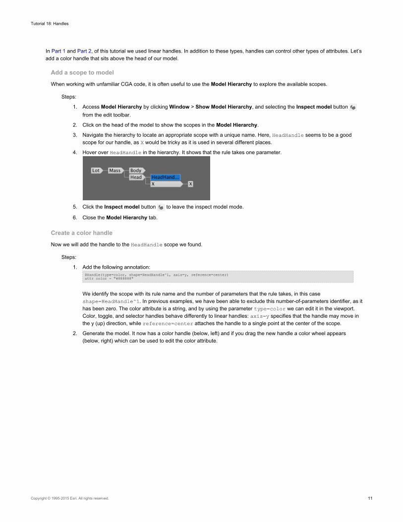
3. Navigate the hierarchy to locate an appropriate scope with a unique name. Here, HeadHandle seems to be a goodscope for our handle, as X would be tricky as it is used in several different places.
4. Hover over HeadHandle in the hierarchy. It shows that the rule takes one parameter.
5. Click the Inspect model button to leave the inspect model mode.
6. Close the Model Hierarchy tab.
Create a color handle
Now we will add the handle to the HeadHandle scope we found.
Steps:
1. Add the following annotation:@Handle(type=color, shape=HeadHandle^1, axis=y, reference=center)attr color = "#888888"
We identify the scope with its rule name and the number of parameters that the rule takes, in this caseshape=HeadHandle^1. In previous examples, we have been able to exclude this number-of-parameters identifier, as ithas been zero. The color attribute is a string, and by using the parameter type=color we can edit it in the viewport.Color, toggle, and selector handles behave differently to linear handles: axis=y specifies that the handle may move inthe y (up) direction, while reference=center attaches the handle to a single point at the center of the scope.
2. Generate the model. It now has a color handle (below, left) and if you drag the new handle a color wheel appears(below, right) which can be used to edit the color attribute.
Tutorial 18: Handles
Copyright © 1995-2015 Esri. All rights reserved. 11
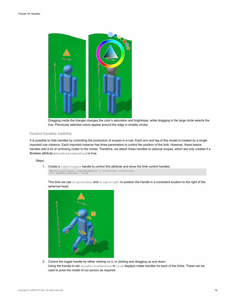
Dragging inside the triangle changes the color’s saturation and brightness, while dragging in the large circle selects thehue. Previously selected colors appear around the edge in smaller circles.
Control handles visibility
It is possible to hide handles by controlling the production of scopes in a rule. Each arm and leg of this model is created by a singleimported rule instance. Each imported instance has three parameters to control the position of the limb. However, these twelvehandles add a lot of confusing clutter to the model. Therefore, we attach these handles to optional scopes, which are only created if aBoolean attribute (showRotateHandles) is true.
Steps:
1. Create a type=toggle handle to control this attribute and show the limb control handles:@Handle(type=toggle, shape=HeadHandle^1, slip=screen, align=right)attr showRotateHandles = false
This time we use slip=screen and align=right to position the handle in a consistent location to the right of thespherical head.
2. Control the toggle handle by either clicking on it, or clicking and dragging up and down.Using the handle to set showRotateHandles to true displays rotate handles for each of the limbs. These can beused to pose the model of our person as required.
Tutorial 18: Handles
Copyright © 1995-2015 Esri. All rights reserved. 12
By default, rotate handles do not move as the view direction changes. They are, however, invisible when viewed from side-on.Rotating the viewpoint around the model often gives better control over the handle. We can see all the handles positioned on ourmodel, and even novice users are able to understand the attributes. So have fun! Explore and discover all the possibilities of handlesand how you can apply them to your models today.
Tutorial 18: Handles
Copyright © 1995-2015 Esri. All rights reserved. 13