Embed Size (px)
Citation preview
TURNING
HARDINGEGS-SeriesPerformance Turning Centers
www.hardinge.com

GS 42
- A2-5, 16C spindle nose- 11-kW (15-hp) spindle drive system- 175Nm (126.5ft-lb) torque- 6,000-rpm spindle speed - 42mm (1.65”) bar capacity
2
GS-Series turning centers are rigid and reliable machines that feature a robust one-piece cast iron base, heavy-duty linear guideways and ballscrews, and many standard value-added features—heavy-duty dual-wound spindle motor, 40-psi through-tool and headwall coolant, foot switch, chip conveyor interface, air hose with air gun, a swing-out CNC control panel for ease of operation, and much more. Oi-TD CNC controls include many value-added features that are offered as options by other machine builders. Choose from the numer-ous productivity options and you’ll have a truly versatile machine—and with the level of quality you would expect with any Hardinge product.
GS-Series PerformanceTurning Centers
Exceptional combination of features for speed, power, accuracy, and durability in a compact design and affordable price
GS 51- A2-6, 20C spindle nose- 11-kW (15-hp) spindle drive system- 210Nm (154ft-lb) torque - 5,000-rpm spindle speed - 51mm (2”) bar capacity
GS 65
- A2-6, 25C spindle nose- 18.5-kW (25-hp) spindle drive system- 504Nm (371.4ft-lb) torque- 4,200-rpm spindle speed - 65mm (2.55”)
Compact and Large Frame

- Collet seats directly in the Hardinge spindle
- Minimum overhang from the spindle bearings assures
that spindle accuracy is transferred directly to the
workpiece
- Maximum rigidity and gripping power is transferred
to the part
- Minimum weight on spindle
- Maximum utilization of RPM
- Optimum T.I.R.
- Gripping force directly over the workpiece
- Superior tolerances and finishes
- Capable of using maximum machine strok capacity
- Quick changeover —collet draw tube is easily and
accurately adjusted from the back of the spindle
- Longer tool life
- Ability to use a wide variety of workholding
devices: Sure-Grip® 3-jaw chucks, collets, FlexC™
quick-change collets, step chucks, Sure Grip®
expanding collets, Dead-Length® systems, fixture
plates and others
Hardinge Spindle shown with Collet
Hardinge Spindleshown with 3-Jaw Chuck
The Hardinge spindle design allows quick changeover from bar work to chucking work!
The Hardinge spindle design is both collet and jaw chuck-ready and does NOT require a spindle adapter. Collet ready spindle available on GS 42, 51 and 65 models.
Minimal distance fromspindle bearings to tool tip
Collet
Grip on bar stock
Excessive overhangfrom spindle bearings
Collet
Bar runout
Collet adapter
The Hardinge Advantage
Minimal distance fromspindle bearings to tool tip
Collet
Grip on bar stock
Excessive overhangfrom spindle bearings
Collet
Bar runout
Collet adapter
3

Industry’s most reliable motors and drives. Heavy-duty axis motors and drives provide superior machine capability.
Non-contact magnetic spindle encoder eliminates the need for belted encoder, increasing overall reliability. One-degree spindle orient included.
Best-in-class spindle design incorporates 2-roller and 2-angular contact bearing for superior rigidity, thermal stability and overall spindle life.
Machine base and all major castings are made with high quality grey cast iron for superior rigidity, durability, and thermal stability.
Dual-wound spindle motor provides heavy-duty cutting capabilities.
Fully-programmable #4 MT hydraulic tailstock option eliminates human intervention compared to competitive designs.
Environmentally friendly grease lubrication minimizes overall maintenance cost.
High class double-nut ball screwsprovide superior machineaccuracy and repeatability.
Strategically ribbed 45-degreeslant bed design of onepiece construction.
High quality linear roller guideways provide greater positioning accuracy, faster traverse rates, less machine wear, longer machine life and overall machining consistency.
GS 65
GS 42 and GS 51
Heavy-duty linear roller guideways provide optimum stiffness and rigidity, resulting in heavier cutting capability and longer machine life.
Fully-programmable #5 MT hydraulic tailstock option features robust boxway design for optimum tailstock rigidity.
Strategically ribbed 30-degree slant bed design of one piece construction.
Heavy-duty, fixed pre-tensioned double-nut C2-class ballscrews provide superior rigidity, machine accuracy and repeatability.
All machines are laser inspected to strict quality standards.
12-Station vertical block top plate standard—VDI top plate withlive tooling is available as an option.
Standard features include:• One-degree spindle orient• Spindle reference (servo lock)• Rigid tapping• Run time and parts counter• Chuck/collet closer foot switch• Chip conveyor Interface• Swing-out CNC pendant • Air hose with air gun • Complete operator’s, programmer’s and maintenance documentation
Machine Construction
4
12-Station vertical block top plate standard—VDI top plate with or without live tooling is available as an option. *BMT for GS65
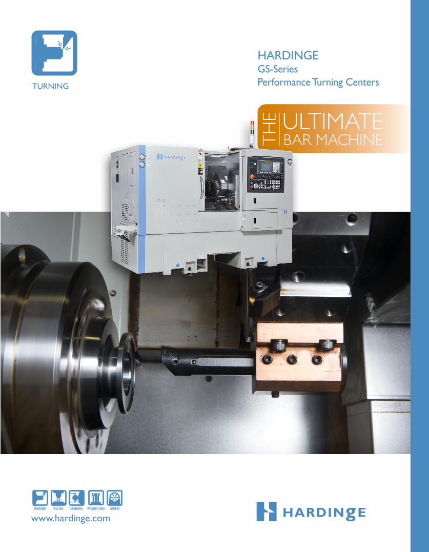
Minimal tool interference Bidirectional turret indexing allows shortest path indexing for reduced non-cut time. The non-lift turret indexing ensures contaminant-free operation—indexing is by a brushless servomotor with positive hydraulic clamping on a 3-piece curvic coupling. The turret pivot (safety shear) feature helps prevent damage to the machine. Coolant is fed through round shank tool holders via turret ports, allowing coolant to be precisely directed to the machining operation. Live tooling is not available.
Rigid tapping Synchronization between the main spindle and the Z-axis motion provides precise and fast rigid tapping operations.
Standard 12-station vertical block top plate
GS 65
GS 42 and GS 51
454m
m(1
7.87
”)
Top Plate Options
5
Large machining area
GS 42 and GS 51 A 112.5mm (4.429”) B 456.0mm (17.952”) C 10.0mm (0.394”) D 152.0mm (5.984”) E 11.0mm (0.433”) F 341.0mm (13.425”) G 117.3mm (4.618”) H 117.3mm (4.618”)
*plus 120mm(4.724”) quill storke
Bidirectional indexing of the 12-station VDI-30 turret top plate allows shortest path indexing for reduced non-cut time. Easier processing of part families and fewer setups are realized due to the fact there are a large number of tool stations. Fast setup times are possible by using quick-change VDI tool holders. The non-lift turret indexing ensures contaminant-free operation—indexing is by a brushless servomotor with positive hydraulic clamping on a 3-piece curvic coupling. The turret pivot (safety shear) feature helps prevent damage to the machine. Coolant is fed through tool holders via turret ports. This allows the operator to direct coolant precisely to the machining operation, providing enhanced cutting and chip management. Live tooling is available as an option. Rigid tapping is included.
Minimal tool interference: GS 42 and GS 51
The illustrations represent the maximum part diameters that can clear adjacent tool holders. A balanced weight distribution of tooling on the top plate is recommended.
*BMT top plate used on GS65 with live tooling
VDI top plate live tooling option

WORKHOLDING
6
Hardinge spindle tooling optionsHardinge manufactures a full line of collets, jaw chucks and quick-changespindle tooling for the most demanding workholding applications.
Collet-Ready Spindle
5C, 16C, 20C and 25C Collets, Hardened and Ground and Emergency
5C, 16C, 20C and 25CStep Chucks and Closers
5C, 16C and 20CDead Length
16C, 20C and 25CMaster Collets and Pads
16C, 20C and 25CSpindle Collet andStep Chuck Adapters
5C, 16C Collet Style
A25, A26 and A28Spindle Mount
FlexC Collet Heads
3 Jaw Chucks
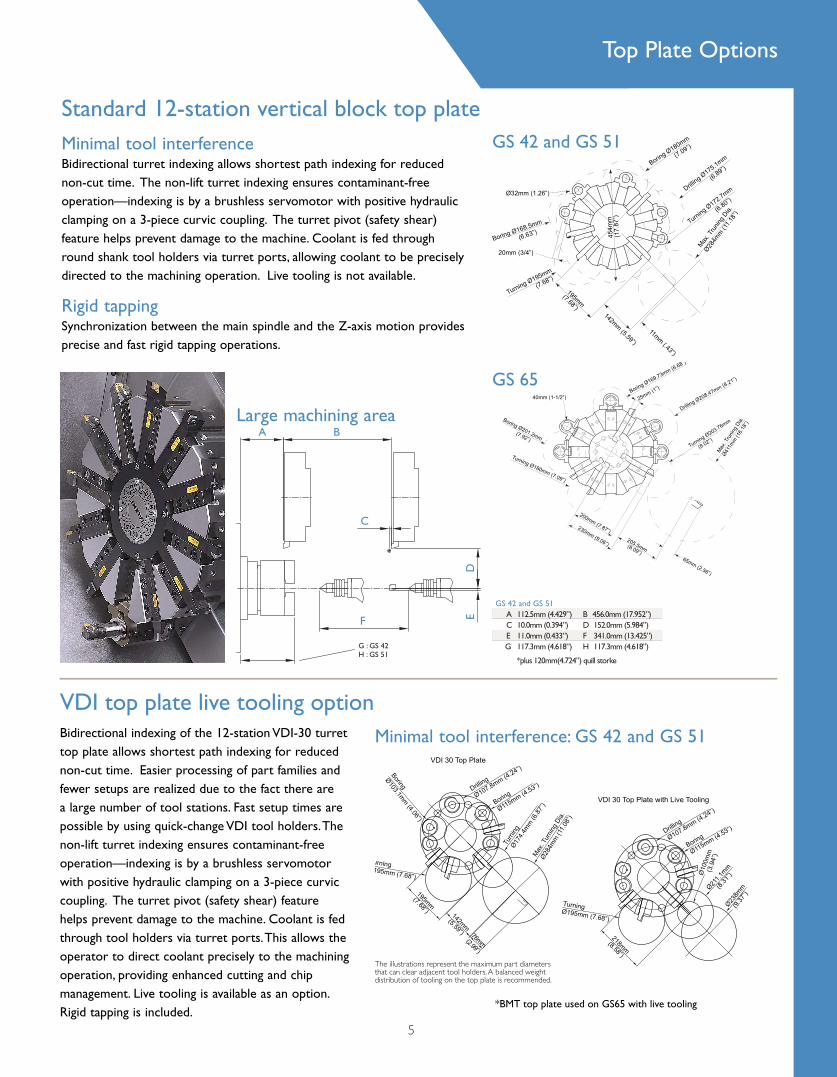
Parts catchers The catcher option allow the operator to conveniently retrieve finished workpieces from outside the machining area during the machining cycle.
Automatic tool touch probeThe retractable probe arm provides quick setup and easy use, enabling automatic insertion of tool offsets. The four-direction probe makes it possible to touch off both internal and external working tools. The machine can also be programmed to automatically touch off tools and be used for in-cycle tool wear and breakage detection. The probe arm swings up to storage position on the headwall.
Thermal Stabilization PackageIncludes a spindle chiller, circulation fan and, X & Z-axis scales. This option will improve the overal thermal stability and minimize the warm up period. This productivity option makes the machine more thermally stable, requiring less human intervention for offset changes during the warm up period. Only available on the GS 42 and 51.
Robust hydraulic tailstocksThe fully-programmable tailstock option offers a robust design for greater stability when machining long components between centers, allowing closer tolerances, better surface finishes and higher speeds and feeds. It is hydraulically positioned and automatically controlled by the part program or manually pressure regulated via the control panel. The GS 65 machine features a MT #5 tailstock with 9354N (2103lb) thrust rating. On the GS 42 and 51 a 5.5m/min (216ipm) maximum feedrate is featured.
Steady rest The steady rest is available on the GS 65 long bed model to support long cylindrical parts, allowing heavier cuts and reduced tooling chatter while maintaining precision tolerances and surface finishes.
Other optional features:- Chip Conveyor - VDI Turret Tooling - Manual VDI Tool Presetter System- Bar Feed Systems- Power Transformers- Stack light- Mist collector
Live tooling/C-Axis contouringThe 5,000-rpm live tooling option eliminates the need for many secondary milling machine operations, reducing additional part handling and setup cost. All stations of the top plate are live-tool ready with only one station actively driven at one time. Separate servomotors are used for turret indexing and live tool operations. A disc-type hydraulic spindle brake provides positive locking during static machining operations.
C-axis provides positioning in increments of .001 degree. Three-dimensional contouring, complex round and prismatic machining, square shoulder and lettering are accomplished by synchronizing the spindle with the X and Z axes. Rigid tapping can be done with both cross-and end-working functions.
20-Bar (280-psi) thru-tool coolantThis high capacity coolant option provides direct flow of coolant to the active tool cutting operation, providing enhanced chip management, higher permissible feeds and speeds, cooler machining conditions for longer tool life and optimum surface finishes.
Part probeThe part probe with macros allows in-process workpiece size verifications and automatic CNC adjustment of work offsets. The probe is capable of performing rapid first-off inspection, in-process reporting and allows “lights out” machining.
Arm-typeGS 42, GS 51 and GS 65
GS 65
Productivity options forenhanced machining performance
Machine Options
7
GS 42 and 51

8
GS-Series Performance Turning Centers Powerful spindle drives
Hardinge/Fanuc High Winding
Spindle Drives
GS 42GS 150 /42
Hardinge/Fanuc High Winding
Spindle Speed (6000rpm) Fanuc Spindle Motor
18.5
16
14
10
12
0RPM
120
100
140
600 1200 1800 2400 36003000 4200 54004800 6000
S3 25% Operating Zone
30min,S3 60%
CONTINUOUS
TorquePowerTORQUE POWER
Nm kW
20
40
60
80
2
4
6
87.5
9
1400750
126
114.5
95.4
Operating Zone
SPIN
DLE
OU
TPU
T P
OW
ER/T
OR
QU
E
Hardinge/Fanuc Low Winding
GS 42
0
2
4
6
8
10
12
200400
600800 1200
1000 RPM
25
50
75
125
150
100
14001500
175
5
9
11
76.3
143.1
kWNm TorquePowerTORQUE
5min operating zone
15min ,S3 15%operating zone
Continuousoperating zone
SPIN
DLE
OU
TPU
T P
OW
ER/T
OR
QU
E
GS 150 /42
Hardinge/Fanuc Low Winding
GS 51
0
2
4
6
8
200400
600800 1200
1000RPM
50
100
150
210
300
200
1250
10
12
500
9
5
11
171
95.4
kWNm TorquePowerTORQUE
5min operating zone
15min ,S3 15%operating zone
Continuousoperating zone
SPIN
DLE
OU
TPU
T P
OW
ER/T
OR
QU
E
GS 200 /51
Hardinge/Fanuc Low Winding
GS 65
0
2.5
5
7.5
10
12.5
15
150300
450600 900
750 RPM1050
50
100
150
250
300
560
17.5
350
409
353
204
18.5
504
450
kWNm TorquePowerTORQUE
5min operating zone
15min ,S3 15%operating zone
Continuousoperating zone
SPIN
DLE
OU
TPU
T P
OW
ER/T
OR
QU
E
GS 200 /66, GS 200/66 L & GS 65
Hardinge/Fanuc Low Winding
GS 51
18.5
16
14
10
12
0RPM
120
100
500 1000 1500 2000 30002500 3500 45004000 5000
S3 25% Operating Zone
30min,S3 60%
CONTINUOUS
TorquePowerTORQUE POWER
Nm kW
20
40
60
80
2
4
6
87.5
9
1167625
137
151160
114.5
Operating Zone
SPIN
DLE
OU
TPU
T P
OW
ER/T
OR
QU
E
GS 200 /51
Hardinge/Fanuc High Winding
Spindle Speed (5000rpm) Fanuc Spindle Motor
GS 65
SPIN
DLE
OU
TPU
T P
OW
ER/T
OR
QU
E
GS 200 /66, GS 200/66 L & GS 65
Hardinge/Fanuc High Winding
Spindle Speed (4200rpm) Fanuc Spindle Motor
0
4
8
12
20
24
6001200
18002400 3600
3000 RPM4200
50
100
150
250
300
26322
770
1516
11
1400
200
273
525
kWNm TorquePower
S3 25%operating zone
30min, S3 60%operating zone
Continuousoperating zone
TORQUE POWER

General213mm (8.4")Color LCD Display • Two Interpolating Axes •Programmable Resolution— 0.001mm (0.0001") • Tool Offset Capability— 0.001mm (0.0001") •Tool Geometry and Tool Wear Offsets (64 pair each) † Inch/Metric Data Selection by G-Code •1280 Meters (512 KB) Part Program Storage †Flash Card Slot Capability (up to 128 MB) †
Data Input/OutputMDI (Manual Data Input) Operation •Reader/Punch Interface Connection(RS-232 Software/Hardware) •DNC (Remote Buffer) †Embedded Ethernet • Single USB Port •
Programming FunctionsAbsolute/Incremental Programming •Additional Tool Offsets (64 pair total) †Additional Custom Macro Variables †AI Contour Control •Background Editing •Blueprint Programming †Canned Cycles (Drilling) •Chamfer/Corner Rounding • Constant Surface Speed Programming •Continual Thread Cutting • Coordinate System Setting (G50) •Custom Macro B †Diameter/Radius Programming •Extended Part Program Edit (Copy/Replace) †Graphic Display † Hardinge Safe Start Format •Input of Offset Value by Programming (G10) •Interpolation (Linear and Circular) •Manual Guide (G-Code Assist) †Multiple Repetitive Canned Cycles I (Turning) † Multiple Repetitive Canned Cycles II (Pockets) †Nano Interpolation •Registered Part Programs (200 total) † Rigid Tapping †Single Block Operation •Spare M-Codes (3) † Thread, Synchronous Cutting •Tool Life Management † Tool Nose Radius Compensation •Variable Lead Thread Cutting † OperationBlock Delete • Clamp/Unclamp Indicator Light Switch • Coolant Control •Dry Run • Dwell Time •Emergency Stop • Feedhold •Feedrate Override (0 to 150%) •Incremental Jog •Jog Feed Override (0 to 1260 mm/min) •Machine Lock •Manual Pulse Generator (MPG Handwheel) •On-Screen Spindle & Axis Load Meters •Option Stop •Rapid Traverse Override (Low-25-50-100%) •Single Block • Spindle Speed and T-Code Displays on All Screens •Spindle Speed Override (50 to 120%) •
Fanuc Oi-TD Control
CNC ControlGS Series Performance Turning Centers
Fanuc Oi-TD Control
9
MiscellaneousAlarm Display •English Color LCD Display with Full Keyboard • French/German, Italian or Spanish OOn-Screen “HELP” Functions for Alarms †Program Protect • Run Time and Parts Counter † Self-Diagnosis Function † Spindle Lock (Servo) •Spindle Orient—One-Degree † Stored Pitch Error Compensation • † Standard value-added features that may be offered as options by other machine builders
• Standard O Optional

GS-Series Performance Turning Centers
10
GS 42 GS 51 GS 65
Spindle
Chuck-Ready Spindle Config.—ANSI 1 A2-5 A2-6 A2-6
Draw Tube Type Hydraulic Hydraulic Hydraulic
Through Draw Tube Capacity 42 (1.65”) 51mm(2”) 67mm (2.63”)
Gripping Capacity 135mm (5.31”) 7.28”/185mm 7.28”/185mm 7.28”/185mm
Machining Diameter—Max. 284mm (11.10”) 284mm (11.10”) 356mm (14.015”)
Turning Length—Max. 2, 3 456mm (17.95”) 456mm (17.95”) 600mm (23.62”)
Hang Weight with Device and Part 34kg (75lb) 48kg (105lb) 70kg (154lb)
Spindle Centerline Height 1,000mm (39.40”) 1,000mm (39.40”) 1,041mm (41.00”)
Operator’s Reach to Spindle 280mm (11”) 280mm (11”) 432mm (17”)
AC Digital Spindle Drive System 4
Fanuc Control (S3)—High Winding
Peak Power Rating 18.5kW (24.7hp) 18.5kW (24.7hp) 26kW (35hp)
Torque Rating 126Nm (93ft-lb) 151Nm (111.3ft-lb) 322Nm (237.6ft-lb)
Base Speed 1400 rpm 1167 rpm 770 rpm
Max. Speed-I-rpm Steps 6000 rpm 5000 rpm 4200 rpm
Fanuc Control (S3)—Low Winding *
Peak Power Rating 11kW (15hp) 11kW (15hp) 18.5kW (24.8hp)
Torque Rating 175Nm (128.4ft-lb) 210Nm (154ft-lb) 504Nm (371.4ft-lb)
Base Speed 600 rpm 500 rpm 350 rpm
Max. Speed-I-rpm Steps 1500 rpm 1250 rpm 1050 rpm
Carriage and Cross Slide
Swing Dia. Over Way Cover—Max. 457mm (18.00”) 457mm (18.00”) 595mm (23.42”)
Travel—Max.—X Axis 153mm (6.023”) 153mm (6.023”) 271.5mm (10.70”)
Z Axis 406mm (16.00”) 406mm (16.00”) 600mm (23.62”)
Traverse Rates—Max.
X and Z Axes 30m/min (1,181ipm) 30m/min (1,181ipm) 30m/min (1,181ipm)
Z-Axis Thrust—Max.
With Fanuc Control 17,907N (4,026lb) 17,907N (4,026lb) 21,991N (4,944lb)
Ball Screw Diameter—X Axis 28mm (1.102”) 28mm (1.102”) 36mm (1.417”)
Z Axis 28mm (1.102”) 28mm (1.102”) 40mm (1.575”)
Evaluation Standard ISO 230-2 ISO 230-2 ISO 230-2
Repeatability—X and Z Axes (ISO) .005mm (.0002”) .005mm (.0002”) .005mm (.0002”)
1—Optional collet adaptation chucks available in many configurations, including 5C, 16C, 20C, 3J, S15, S20, B42 and B60.
2—Dependent on type of live center used.3—Maximum turning length with tailstock option.4—Peak ratings used for power and torque specifications.
5—Index time (includes unclamp and clamp).6—Original equipment only. 7—Available on VDI top plate only. 8—Balanced, 3-phase. *—Availability may be limted to certain markets.
Specifications

GS 42 GS 51 GS 65
Spindle
Chuck-Ready Spindle Config.—ANSI 1 A2-5 A2-6 A2-6
Draw Tube Type Hydraulic Hydraulic Hydraulic
Through Draw Tube Capacity 42 (1.65”) 51mm(2”) 67mm (2.63”)
Gripping Capacity 135mm (5.31”) 7.28”/185mm 7.28”/185mm 7.28”/185mm
Machining Diameter—Max. 284mm (11.10”) 284mm (11.10”) 356mm (14.015”)
Turning Length—Max. 2, 3 456mm (17.95”) 456mm (17.95”) 600mm (23.62”)
Hang Weight with Device and Part 34kg (75lb) 48kg (105lb) 70kg (154lb)
Spindle Centerline Height 1,000mm (39.40”) 1,000mm (39.40”) 1,041mm (41.00”)
Operator’s Reach to Spindle 280mm (11”) 280mm (11”) 432mm (17”)
AC Digital Spindle Drive System 4
Fanuc Control (S3)—High Winding
Peak Power Rating 18.5kW (24.7hp) 18.5kW (24.7hp) 26kW (35hp)
Torque Rating 126Nm (93ft-lb) 151Nm (111.3ft-lb) 322Nm (237.6ft-lb)
Base Speed 1400 rpm 1167 rpm 770 rpm
Max. Speed-I-rpm Steps 6000 rpm 5000 rpm 4200 rpm
Fanuc Control (S3)—Low Winding *
Peak Power Rating 11kW (15hp) 11kW (15hp) 18.5kW (24.8hp)
Torque Rating 175Nm (128.4ft-lb) 210Nm (154ft-lb) 504Nm (371.4ft-lb)
Base Speed 600 rpm 500 rpm 350 rpm
Max. Speed-I-rpm Steps 1500 rpm 1250 rpm 1050 rpm
Carriage and Cross Slide
Swing Dia. Over Way Cover—Max. 457mm (18.00”) 457mm (18.00”) 595mm (23.42”)
Travel—Max.—X Axis 153mm (6.023”) 153mm (6.023”) 271.5mm (10.70”)
Z Axis 406mm (16.00”) 406mm (16.00”) 600mm (23.62”)
Traverse Rates—Max.
X and Z Axes 30m/min (1,181ipm) 30m/min (1,181ipm) 30m/min (1,181ipm)
Z-Axis Thrust—Max.
With Fanuc Control 17,907N (4,026lb) 17,907N (4,026lb) 21,991N (4,944lb)
Ball Screw Diameter—X Axis 28mm (1.102”) 28mm (1.102”) 36mm (1.417”)
Z Axis 28mm (1.102”) 28mm (1.102”) 40mm (1.575”)
Evaluation Standard ISO 230-2 ISO 230-2 ISO 230-2
Repeatability—X and Z Axes (ISO) .005mm (.0002”) .005mm (.0002”) .005mm (.0002”)
Actual results may be greater or less than those listed due to a number of factorsincluding but not limited to warm up cycles, speeds, feeds, tooling, machine maintenance, coolant, material, ambient temperature and type of machine foundation.11
Specifications
GS 42 GS 51 GS 65
Turret Top Plate—Bidirectional Vertical Block or VDI 30 Vertical Block or VDI 30 Vertical Block or VDI 40
Number of Station 12 12 12
Square Shank Tool Size—Max. 20mm or 3⁄4” 20mm or 3⁄4” 25mm or 1”
Round Shank Tool Size—Max. 32mm or 11⁄4” 32mm or 11⁄4” 40mm or 11⁄2”
Index Time—Adjacent Station 5
Vertical Block .46 Second .46 Second .3 Second
VDI 0.78 Second 0.78 Second 0.78 Second
VDI Live Tooling/C-Axis Option 6, 7
Tool Shank Diameter w/ER25 Collets 2 to 16mm 2 to 16mm 2 to 16mm
.079 to .625” .079 to .625” .079 to .625”
Power Rating at Tool Tip 4 3.7kW (5hp) 3.7kW (5hp) 8kW (10.5hp)
Torque Rating at Tool Tip 4 25Nm (18.44ft-lb) 25Nm (18.44ft-lb) 35.0Nm (25.80ft-lb)
Maximum Speed—1-rpm Steps 5,000 5,000 4,000
C-Axis Contouring Resolution .001 Degree .001 Degree .001 Degree
Positioning Accuracy ± 1 Arc Min. ± 1 Arc Min. ± 1 Arc Min.
Repeatability 1.75 Arc Min. 1.75 Arc Min. 1.75 Arc Min.
Tailstock (Fully-Programmable) Option 6
Positioning Hydraulic Hydraulic Hydraulic
Morse Taper Center MT No. 4 MT No. 4 MT No. 5
Travel of Tailstock Base 341mm (13.42”) 341mm (13.42”) 625mm (24.60”)
Part Length—Max. 2, 8 499.7mm (23.62”) 499.7mm (23.62”)
Min. 2 42.7mm (1.68”) 42.7mm (1.68”) 20.0mm (0.787”)
Feedrate—Max. 5.5 m/min (216ipm) 5.5 m/min (216ipm) 5.5 m/min (216ipm)
Thrust—Max. 3,470N (780lb) 3,470N (780lb) 9,354N (2,103lb)
Parts Catcher Option
Workpiece Dia. x Length—Max. 52 x 100mm 52 x 100mm 65 x 160mm
2.05 x 4” 2.05 x 4” 2.56 x 6.3”
Miscellaneous
Power Supply Requirement 8
Fanuc Control 220v/67FLA/3phase 220v/67FLA/3phase 220v/74FLA/3phase
Coolant Tank Capacity 125liter (33gal) 125liter (33gal) 290liter (76.62gal)
Coolant Pressure—Standard 2.8bar (40psi) 2.8bar (40psi) 2.8bar (40psi)
Thru-Tool Coolant Option 20bar (280psi) 20bar (280psi) 20bar (280psi)
Machine Weight—Approx. 2694kg (5,940lb) 2794kg (6,160lb) 4950kg (10,915lb)
Shipping Weight—Approx. 3057kg (6,739lb) 3157kg (6,959lb) 5290kg (11,664lb)
Machine Dimensions
Length 1998mm (78.66”) 1998mm (78.66”) 2988mm (117.64”)
Length w/Chip Conveyor Option 2958mm (116.46”) 2958mm (116.46”) 3672mm (144.60”)
Depth 1650mm (65”) 1650mm (65”) 2142mm (84.33”)
Depth w/Control Unit at Max. Swivel 2153mm (84.76”) 2153mm (84.76”) 2453mm (96.58”)
Height 1781mm (70.12”) 1781mm (70.12”) 1812mm (71.34”)
Floor Area—Approx. 3.3m2 (35.5ft2) 3.3m2 (35.5ft2) 5.1m2 (54.9ft2)

All specifications subject to change without notice.
All marks indicated by ® and ™ are trademarks of their
respective owners. Brochure #1326F • Litho in USA •
©Hardinge Inc. 2014 • July 2014
Over the years, The Hardinge Group™
steadily diversified both its product offerings
and operations. Today, the company has
grown into a globally diversified player with
manufacturing operations in North America,
Europe and Asia. In addition to designing and
building turning centers and collets, Hardinge
is a world leader in grinding solutions with
the addition of the Kellenberger, Jones &
Shipman, Hauser , Tschudin and Usach brands
to the Hardinge family. The company also
manufactures Bridgeport machining centers
and other industrial products for a wide range
of material cutting, turnkey automation and
workholding needs.
Expect more from your Hardinge
products. Choose Hardinge precision
and reliability for increased productivity
and value!
Call us today, we’ve got your answer.
Competence and worldwide partnership
HardingeCompaniesWorldwide
North AmericaHardinge Inc. One Hardinge Drive Elmira, NY 14902-1507 USA General Information: 607-734-2281 Sales Fax: 607.734.8819 Workholding Fax: 607.734.3886 Service: 800.424.2440 web site: www.hardinge.com
In Canada Canadian Hardinge Machine Tools Ltd. Tel: 800.468.5946 Fax: 607.734.8819
China Hardinge Machine (Shanghai) Co. Ltd.Hardinge China Limited No.1388 East Kang Qiao Road Pudong, Shanghai 201319 Tel: 0086 21 38108686 Fax: 0086 21 38108681
Hardinge Precision Machinery (Jiaxing) Co., Ltd.Economic and Technology Development Zone No. 2676 Wango Road Jiaxing, Zhejiang PRC 3144001 Tel: 0573-82601088 Fax: 0573-82601988
Germany Hardinge GmbH Fichtenhain A 13 C 47807 Krefeld Germany Tel: (49) 2151 496490 Fax: (49) 2151 4964999
Taiwan Hardinge Machine Tools B.V. 4 Tzu Chiang 3rd Road Nan Tou City 540 Taiwan, R.O.C. Tel: 886 49 2260536 Fax: 886 49 2252203 e-mail: [email protected]
Switzerland L. Kellenberger & Co. AG Heiligkreuzstrasse 28 Postfach Ch-9009 St. Gallen Switzerland Tel: +41 (0) 71 242 91 11 Fax: +41 (0) 71 242 92 22 e-mail: [email protected] web site: www.kellenberger.net
L. Kellenberger & Co. AG Längfeldweg 107 CH-2500 Biel-Bienne 8 Switzerland Tel: +41 (0)32 344 11 52 Fax: +41 (0)32 341 13 93 e-mail: [email protected] web site: www.kellenberger.net
United KingdomHardinge Machine Tools, Ltd. Whiteacres Cambridge Road Whetstone Leicester LE8 6BD England Tel: +44 (0)116 2869900 Fax: +44 (0)116 2869901 Hardinge e-mail: [email protected] Hardinge web site: www.hardinge.co.uk
Jones & Shipman PrecisionLimited Murray Field Road Leicester LE3 1UW, UK Tel: +44 (0) 116 2013000 Fax: +44 (0) 116 2013001 e-mail: [email protected] web site: www.jonesshipman.com