Embed Size (px)
Citation preview

Turntable
TT-10

IMPORTANT SAFETY INSTRUCTIONS
CAUTION: To reduce the risk of electric shock, do not remove
the cover. There are no user-serviceable parts inside; it is
recommended that only qualified personnel service this
component.
1. OWNER’S MANUAL: Before powering up the equipment,
read all safety and operating instructions and follow them as
instructed. Retain the safety and operating instructions for
future reference.
2. ATTACHMENTS: Use only those attachments
recommended by the unit manufacturer, as others may cause
hazards.
3. ACCESSORIES: Do not place the unit on an unstable cart,
stand, tripod, bracket, or table. The unit may fall, causing injury
to a person or damage to the unit. Mount the unit according to
the manufacturer’s instructions with the suggested mounting
accessory.
4. WATER AND MOISTURE: Do not use the unit near water
(for example, near a swimming pool, bath tub, wash bowl,
kitchen sink, or laundry tub) or in a damp environment (like a
basement or outside in the rain).
5. OBJECT AND LIQUID ENTRY: Do not push objects of any
kind into the unit through openings as they could touch
dangerous voltage points and short-out parts, possibly
resulting in a fire or electric shock. Avoid spilling liquid of any
kind on the unit. If water or any metal object (such as a paper
clip, coin, or staple) accidentally falls inside the unit,
disconnect it from the AC power source immediately and
contact Margules Audio for further instructions.
6. HEAT: Position the unit away from heat sources such as
radiators, heat registers, stoves, or other units (including
amplifiers) that produce heat.
7. GROUNDING OR POLARIZATION: As a safety feature, the
unit may be equipped with a polarized alternating current line
plug in which one blade is wider than the other. This plug will fit
into the power outlet only one way. If you cannot insert the
plug fully into the outlet, try reversing the plug. If the plug still
will not fit, contact a licensed electrician to update your
obsolete outlet. Do not defeat the safety purpose of the
polarized plug.
8. POWER SOURCES: Operate the unit only from the power
source indicated on the marking label. If you are unsure of the
type of power supplied to your home, consult your unit dealer
or local power company.
9. POWER CORD PROTECTION: Arrange power supply
cords so that they do not suffer from foot traffic or pinching by
items placed on or against them. Pay close attention to cords

where plug enter the AC outlet and where they exit from the
unit.
10. OVERLOADING: Do not overload wall outlets, extension
cords, or integral convenience receptacles as this increases
the risk of fire or electric shock
11. REPLACEMENT PARTS: When replacement parts are
required, be sure the service technician has used replacement
parts specified by the manufacturer or those having the same
characteristics as the original parts. Unauthorized substitutions
may result in fire, electric shock or other hazards.
12. SAFETY CHECK: Upon completion of any service or
repairs to the unit, ask the service technician to perform safety
checks to ensure the unit is in proper operating condition.
13. IMPORTANT SAFETY NOTE:
• Power Cord: The removable power cord provided with your
player was specifically designed for use with this product, but
other AC cords may be used. Consult your dealer for advice on
AC power cords and high quality wire in your system.
• Wiring: Cables running inside walls should have the
appropriate markings to indicate compliance and listing by the
UL, CSA or other standards required by the UL, CSA, NEC or
your local building code. Questions about cables inside of
walls should be referred to a qualified custom installer, a
licensed electrician, or low-voltage contractor.
14. RECORDING COPYRIGHT: Recording of copyrighted
material for other than personal use is illegal without
permission of the copyright holder.
15. NOTE TO CATV SYSTEM INSTALLER: This reminder is
provided to call the CATV system installer's attention to article
820-40 of the NEC, ANSI/NFPA 70, which provides guidelines
for proper grounding and, in particular, specifies that the cable
ground shall be connected to the grounding system of the
building as close to the point of cable entry as practical.
26. FCC INFORMATION FOR USER:
• CAUTION: Any changes or modifications
not expressly approved by Margules Audio
could void the user's authority to operate
the equipment.

Introduction
This drawing of the stereo groove may look frightening
yet...
... But if you stick to the basic adjustments, you can enjoy the sound of analog recordings engraved in the vinyl record. It is not at all necessary to make things complicated. Start by adjusting down force and bias, put on a record and listen. From there you can refine the set up and adjustments if you want the highest quality in sound. If the adjustments are not correct, even the most expensive
turntable cannot fulfill its promise: the best possible sound
reproduction.
Preamble Why not has a turntable next to your CD player in your set up? The sound of records can be enlightening, records are authentic, and records can be fun. Compared to the modern digital formats, the analogue LP record, with its signal engraved in a vinyl disc may look poor at first glance.
However, do never forget that it is still the only medium (apart from the reel to reel tape recorder) that can contain the most complete and most structured signal providing great dynamics, having the widest frequency band attainable, and having the most refined detail over the entire audio spectrum and far beyond, which no other format can deliver. The analog LP is not restricted to 16 bits and a limited frequency band, but has 700 bits - so to speak - and the minute upper harmonics which digital formats are missing. The simple reason is that the original LP is analogous in nature. Or, to be more precise: analogous to nature. Performance versus CD If your CD outperforms your analog setup, than you do not have the right combination of components. In other words you forgot about "system building". There are some general and specific do's and don'ts. Here are a few: - Look for voluptuous sound, yet well controlled, look for realism. - Look for a good, spacious mid band. - Do not connect low efficiency loudspeaker systems to a 10 or 25 Watt tube amplifier or to a high current amplifier, but use a power amplifier delivering current stored in a large reservoir of Micro Farads. - Match cartridge and arm properly: mass (weight of the arm) in relation to compliance. - Choose the right preamplifier to match the impedance and/or capacitance of your cartridge. Make the necessary adjustments. - Carefully position your loudspeakers in the listening environment.

- Follow your taste and ears. Go to live concerts of classical music and jazz. There you will find that high-end does not exist in reality, only realism. - Do not take the PA set-up during a live concert of your favorite rock band as a reference. Because that sound is no reference at all. Many of those experts who move the faders have a hearing problem. And soon you may have one too. - Be well advised, but forget about the hype which surrounds so many components and is repeated by so many and far too often. - Do not be distracted and confused by a member of a forum
who says that this page gives - in his opinion - at some
instances incorrect advice. Only believe him if he points out
what is incorrect. You will notice that he never does.
Even if new and more complex and high resolution digital formats are being developed and there are no appropriate players for these formats, the recording can be engraved in a vinyl record and can be fully enjoyed. Even hundreds years from now.
Leveling the turntable
It is of the utmost importance to adjust the turntable with arm and phono cartridge correctly. Place the turntable on a strong cabinet, in an audio rack or on a special construction that is bolted to the stone wall of the listening room. These supports should be level. See to it that the turntable is perfectly level also. This is essential to minimize wow and flutter. It is also a prerogative for the proper functioning of the phono cartridge and the arm. Only if the turntable is level the down force and bias (side thrust) can be adjusted correctly.
To check if you have done it right just push the spindle down with your index finger, the platter should go down and come up always staying level. That means that the platter should not rock or wobble. If it does you have to make new adjustments. Adjusting is done by unscrewing the tips of the cones, the base of the motor and the third feet is fix, so all adjustments should be referred to the motor base. The motor is suspended to avoid vibration transmission to the main frame.
Figure 1. Unscrew the tip of the cones for leveling adjustment

Connections
First, connect the RCA (1) output and ground (2) from the
turntable to the FZ 47 DB phono preamplifier input (3) and
ground (4) respectively. Then connect the output of the phono
amplifier to your pre amplifier. Finally, plug both equipment to
the 127 AC. For more information see the next diagram. This is
only for the interconnection between the TT10 turntable and
the FZ 47 DB, look for the interconnections for your own phono
stage.
Diagram 1. Interconnection between the turntable and the phono stage FZ 47 DB

Vertical tracking angle
A. Initial adjustment
Check whether the arm and the head shell are parallel to the record. Most manufacturers of cartridges take care to mount the tip and cantilever in such a way that a Vertical Tracking Angle (VTA) of round and about 20 degrees is achieved when the arm is parallel to the record. The standard today is 20º. Vintage cartridges from the nineteen sixties for instance have a tracking angle of 15º. The final VTA adjustment will be done later after you have adjusted the azimuth and down force and bias have been precisely set. The VTA adjustment is possible thanks to three screws in the base of the arm. The Margules A1.2 TT10 arm is unipivot. It is important that the tone arm is free and can have movement to the sides, up and down. If the base is not level properly you might have problems with the arm elevator or restrictions the movement.
B. Azimuth adjustment
Now check the cartridge seen from the front. It should be perpendicular to the record. This is easily checked using a small mirror. A precise way of measuring the azimuth is by using a test record and a voltmeter. But this can only be done after the correct down force and bias have been adjusted. In Margules Arm this can be adjusted by rotating the eccentric weight in the back of the arm.
Figure 2. Use a small mirror to see if the cartridge is perpendicular (front
sight)
C. Azimuth replacement stylus
If you have bought a replacement needle, check if the tip is really well mounted. Check the cantilever from the front with a magnifying glass. The cantilever should be perpendicular to the cartridge body. The tip should be in line with the cantilever. It is a good practice to take the small art director's magnifying glass with you to the shop and insist that you check before you pay. A needle tip which is out of line cannot read the stereo groove. Just to be sure.

Figure 3. A) The cantilever is not perpendicular. B) The cantilever is in good
position.
Lateral tracking error
While engraving the lacquer disc (from which the matrix is
made), the cutter head moves laterally from the outside of the
lacquer to the inside. At all instances the cutter diamond
makes a 90 degree angle with the groove it has cut. This
movement can be imitated by a tangential tone arm. Most tone
arms however are not tangential or parallel tracking tone arms
but radial arms which move along a fixed radius. The result is
that during play the lateral angle varies. The diamond of the
cartridge does not completely mimic the path originally made
by the cutter head.
Use the gage supplied with the turntable and the instructions in
it or in the next paragraphs you will find interesting information.
Overhang
When using a radial arm, there is practically at every instance
a tracking error which results in a time difference between the
signals of the left and right channel. Just a few milliseconds!
Therefore it is necessary to mount the phono cartridge in the
tone arm in such a way that this time difference is kept to an
absolute minimum. Adjusting the arm in accordance with the
specified overhang (and of course the distance between
spindle and arm base as supplied) can give the least tracking
error.
Figure 4. Overhang: distance between the needle tip and the spindle

Figure 5. Description of each important specification
The alignment of cartridge and arm has to be done in
accordance with the technical specifications given by the
manufacturer of the pick-up arm:
Total tone arm length
Effective length
Overhang
Offset angle (angle of headshell in relation to the arm
tube; this angle changes in relation to the length of the
arm)
Overhang is the distance between needle tip and center of the
spindle. This can be seen when the cartridge is placed above
the spindle (if the arm does allow this). The effective length is
the distance between pivot and diamond tip. The offset angle
is the angle between head shell and arm tube, see figure 5 for
more details.
The data of the manufacturer make it possible to determine the
correct position of the arm in case you add an arm to the TT10.
Many times one encounters a tone arm which is not built
according to the findings and theories devised by various
technicians, researchers and mathematicians. But even if the
data of the arm are not according to the findings, it is possible
to find the best position of the pivot in relation to spindle and
cartridge, and in relation to the groove. No need to worry, and
no need to study mathematics and trigonometry.
You may decide for yourself if you want the least distortion in
the inner grooves (close to the label) were generally the most
distortion is generated. Or you may align the cartridge in such
a way that zero distortion is achieved at distances of 66 mm
and 120.9 mm from the spindle.

You can draw a protractor yourself. Or just print in real size the
diagrams that are in this manual. From the template of figure 6
each square should measure 5 millimeter. If necessary adjust
the size of the image so that two squares are 10 mm (=1 cm).
Place the cartridge over the 120.9 mm line with the needle tip
precisely at the crossing. The cartridge's body should be
parallel to that line. Now lift the cartridge, move it and place it
over the 66 mm mark. Again the needle tip has to be placed
exactly at the point where the lines cross (you need to turn the
platter a little by hand). Then at that point the cartridge's body
should again be parallel to the line when the diamond tip is
placed over the spot.
You have to adjust the arm and cartridge in such a way that at
both points the configuration is exact. This template gives a
general and useful indication. However, there are arms that
were designed with a completely different geometry.
Add to this that most of the time very loud passages are
engraved, and you will understand that optimal tracking has to
be near the end of the record. But only then if the angle is not
too much elevated on other spots.
The template of figure 7 can tell you what the measure of
lateral tracking angle in degrees is. Does not matter at what
point you do measure. You can choose the least error at
whatever distance from the spindle.
The template enables you to check the error of the Lateral
Tracking Angle at every position of the arm. You can start at
the small circle. But you also can choose a different point of
departure, closer to the spindle. For instance at (c). See to it
that at your starting point the front of the cartridge is parallel to
the line marked 0°. After that you can check at various points
and see what the error is: + or - one or more degrees. You can
save this drawing and print it and enlarge it so that the
distance between A and B is 15 cm.
Apart from these two templates that include our manual, we
gave you another protractor at the moment you buy the TT10
turntable. Use the one that is most convenient for you.

Figure 6. Protractor
Figure 7. Lateral
tracking error

Not all arms were built with the optimum geometry in mind,
especially those which have a fixed mount. So in certain cases
it can be necessary to shift the cartridge in the head shell a
little. This means that you are changing the lateral tracking
angle and possibly optimizing the geometry of the arm. This
can only be done if the headshell has slots. Always use a
template pictured to measure the error.
If the headshell does not have slots you can make these
yourself or if you are not handy have them made. That makes
it possible to align a cartridge in a tone arm of which you do
not have specifications. Just follow the directions given above
using the template and find the lowest degree of error and
distortion.
Figure 8. Shifting the cartridge makes it possible to optimize the offset angle
of the tone arm and to certain extend the overhang and the effective length.
How to set the cartridge
To set the VTA on the TT-10 use the protractor that was given
with your turntable, and follow the next instructions. But, as we
said, use the one that is most convenient for you.
1. - Place the template with the A point in the center of the
spindle and the arrow pointing out the pivot, both will have to
be in the same line.
2. - Place your cartridge in the headshell but do not set it yet,
just until you adjust the tip of the cantilever to rest on the point
B. Once you have achieved that, set the cartridge in its place.

3. - With a jewelry scale measure the downforce of the
cantilever. This is relevant to the cartridge you are using. It is
mention in the instructions of your new cartridge. If the
downforce is out of the range, you have to adjust the weight on
the back of the arm, to increase the pressure on the cantilever.
4. - Now, check that the base of the cartridge is parallel to the
platter, so it can read right the record. For this you have to
adjust the eccentrical weight. If the cartridge is lean to one
side, just turn the eccentrical weight to the opposite direction.
5. - Once you have the cartridge parallel to the platter it is
recommended to measure the downforce again of the
cantilever using the same jewelry scale, just to check if the
weight is within the range.
Down force – VTF
Apply the amount of down force (Vertical Tracking Force) as
indicated by the manufacturer of the cartridge. Never use a
down force that is too light. Not enough down force is generally
more detrimental to the record groove than a down force which
is slightly too heavy.
Each time after adjusting the down force does listen to the
result. It takes some practice and listening experience to find
the optimum down force. If the sound of a saxophone is too
light and shows an accentuation in the midband with a slight
resonance, than the down force (in relation to the bias setting)
is too light. If a clarinet gets too muddy the down force is too
heavy. In that case also the sound image will lack in space. In

practice the down force is hardly ever the exact value as given
by the manufacturer.
If you do not use an original diamond tip offered by
the manufacturer of the cartridge, you cannot rely on the
specifications of the cartridge any longer. Specifically, if it is an
old cartridge. The replacement needles often do not have the
precisely cut and polished tips, the tips may have slightly more
mass. In case of a moving magnet type both the rubber and
the magnet may not be comparable with the original quality. So
it is possible that a new manufactured tip will alter the
performance of the cartridge: compliance and tracking ability,
band width, frequency characteristic and dynamics. In that
case you also have to find the best down force and side thrust
which can be completely different from the values of the
original cartridge.
Bias compensation
When a disc is spinning and you place a small object on it, the
object will be swept off the disc by the centrifugal force (CF).
You can try this yourself by placing a small object on the
platter. When a record is turning, and the needle tip is held in a
spiral groove at one end and the tone arm is fixed on the other
end, a force will be exercised on the arm and cartridge. This
force has now become a centripetal force (CP) which will move
the cartridge towards the spindle, all caused by the fixation at
the pivot of the arm. Now the arm can only move in a radial
way as it is held in position by the pivot. The result is that
there will be an increased pressure on the groove wall
which contains the sound of the left channel. In order to
neutralize this force, and to give both groove walls equal
pressure, it is necessary to compensate this effect by applying
a counteracting force at the other end of the arm, passed the
pivot (BA). The force to be applied is called side thrust
compensation or bias compensation. It is done by means of a
pending weight or a magnetic force.
A linear/parallel tracking arm does not need this
correction because the pivot continuously changes its position.

When adjusting the bias or side thrust (BA) precisely, use a
test record with a groove-less section. The right amount of side
thrust compensation (in relation to the down force) will keep
the cartridge from moving either towards the spindle or
towards the periphery of the LP record. You may also play the
tracks of a test record containing heavily modulated signals for
left and right, and listen carefully at what level of bias
compensation + down force the distortion is the least, or even
completely absent.
If you are a perfectionist, you may connect an oscilloscope
alternately to the left and right outputs of your preamplifier (or
the Record Out sockets), and check the bias adjustment by
playing the test with separate left and right channel signals, in
various modulations, starting at 50 um. The use of a Clamp
makes it possible to choose a more precise down force and
bias as the use of these gadgets do reduce distortion already
to a great extend. This will result in a better adjustment and a
much better signal.
Figure 9. A correctly adjusted down force combined with the right bias will give a pure stereo image with the least distortion.

Final adjustment from the verical tracking angle
Figure 9 is a drawing of the cutterhead of a lathe. The cutter
diamond moves in a complex way so both left and right signals
(for the left and right channels) are engraved in the lacquer.
Figure 10. Parts of a cutterhead
When engraving the lacquer, the cutter diamond moves up and
down over a short distance. Whether the movement is more an
arc or just a straight line depends on the position of the cutter
head and the position of the diamond. In theory this movement
is a perpendicular movement (a) from figure 11, but it is likely
not to be a straight line (b). The cutter head should be
positioned the correct way so that the cutter diamond operates
under an angle of 20º. Yet it is possible that the Cutter Rake
Angle (the way the cutter diamond is mounted) is incorrect and
the 20º are not met. If all is correct, the Cutter Diamond Angle
must be imitated by the cartridge.
Figure 11. Cutter diamond movements
For monophonic records only the adjustment of the lateral
tracking angle is of importance. The stylus should ride in the
middle of the groove at the correct down force.
With the introduction of the stereo record and its complicated
signal, it became clear that a record can be cut in more than
just one way. The vertical position of the diamond stylus in
the cutter head can vary and the result is that the pattern of
the groove changes also.

As said, the diamond tip of the cartridge has to be in the same
position as the cutter diamond. Only then will the signal be as
precise as possible.
The engineers explained what the Vertical Tracking Angle is. A
few mentioned other parameters of significance as well.
VCU = the Vertical Cutting Angle. It should be set exactly as
prescribed in the manual of the cutting lathe.
CRA = the Cutter Rake Angle. This is the angle of the cutter
diamond in relation to the cutter head. This angle should
actually be the same as the VCA, the Vertical Cutting Angle. If
it is not, than an engraving giving an awkward signal is the
result.
VTA = the Vertical Tracking Angle of the diamond tip (stylus) in
the cartridge. It should be exactly the same as the Vertical
Cutting Angle.
SRA = the Stylus Rake Angle. This is the angle the stylus
makes in relation to the cantilever and the body of the
cartridge. The SRA should be identical to the Vertical Tracking
Angle (VTA) when the top of the cartridge is mounted parallel
to the record's surface. If the Stylus Rake Angle (SRA) is not
identical to the VTA, the SRA has to be adjusted until it
reaches the correct VTA and mimics the cutter diamond. One
method to achieve this is by adjusting the height of the arm at
the pivot. The headshell will no longer be parallel to record's
surface. Another method is to put a wedge in between
cartridge and headshell. Since the engraved signal in the
record measures micrometers, it is obvious that if the SRA is
incorrect, a higher level of distortion will be heard. See the
figure 12.
Figure 12. Stylus rake angle

Figure 13. A) Theorical ideal, B) Wrong VTA and C) Wider SRA
Let us view the other drawings. From figure 13:
(A) represents the theoretical ideal: CRA, VCA, SRA and VTA
are all the same, they coincide.
In (B) the stylus is perpendicular to the record's surface, but
the Vertical Tracking Angle is incorrect. Because the stylus is
incorrectly mounted at the end of the cantilever, the diamond
tip is not in a position to read the indentations in the groove
correctly. The best thing to do is to make a height adjustment
at the pivot.
(C) shows the case when the groove is cut under a wider angle
than the prescribed 20º. The correct position of the stylus of
the cartridge can only be found by making a substantial height
adjustment at the pivot, or by putting a wedge in between the
cartridge and headshell.
The best advice is to adjust the arm at its basis (pivot) in
such a way that the best sound reproduction for most
records is obtained.
The VTA will generally vary when playing a record which is not
completely flat or is warped. If there is continuous variation in
arm movement (up and down and/or swinging excessively)
when playing a perfectly pressed LP, than it could well be that
the arm is too heavy for your cartridge. Your cartridge has
probably a high compliance and needs a lighter arm. Check
the parameters of arm and cartridge. It is very important to set
the correct VTA if you want to obtain a detailed sound with
beautiful high frequencies, with warmth and attack at the same
time. Lowering the arm at the pivot so that the cartridge will

lean slightly back will give a round and less detailed midband.
Adjusting the arm at the pivot so that the cartridge leans more
forward gives a more detailed sound. If the cartridge leans too
far forward the sound becomes hollow and unnatural, the
harmonics will suffer. Especially with fine line diamond tips and
the Van den Hul tip the precise VTA is of the utmost
importance. You have to find the best adjustment for
harmonious sound which has a lot of fine detail at the same
time. So listen carefully! In the end the determination of the
best VTA can only be done by ear.
Choose the VTA with which all records sound good
As not all records have been cut at the same angle, there is a
slight problem. At the end of the nineteen seventies The Audio
Critic suggested the idea of optimizing the VTA for each and
every record you would play. The idea was simple: use
cardboard of varying thickness (millimeters) and cut these to
the size of the turntable mat (or I would suggest: about 28 cm
in diameter). Adding cardboard discs in between record and
turntable mat may give an optimum VTA but will also change
the contact of LP and mat, and it will change the "color" of the
sound reproduction. So cardboard discs are out of the
question, at least for me personally.
Fortunately, we have design an arm of which the VTA can be
changed. Our turntable arm base is design to enable an
adjustment in any direction: up and down, left and right. This is
possible by changing the height of three allen screws that are
under the arm base.
Adjust them until you find the point where the head axis appear
“floating” over the pivot, or in other words, when it can easily
moves to the sides (see figure 14 a). It also important to adjust
the arm in a parallel position to the record. This two point are
the key for the best VTA.
In one side of the base is the lifter lever that allows you to lift
and lower the tone arm. When it is lifted, we recommend to
have a distance of 3mm from the record, to protect them of any
damage, see figure 13 b.
Figure 14. A) The head axis will seems to “float”. B) Left 3 mm between the record and tone arm

IMPORTANT: Some audiophiles add a small wedge when they
think it necessary to adjust the VTA in specific cases. Placing a
wedge can help in rare cases. But placing a plate, piece of
rubber, felt, or whatever material you choose (as is sometimes
advised by so called knowledgeable audiophiles) in between
cartridge and headshell should not be done. It provides a
"loose" contact between cartridge and headshell. Placing a
material between cartridge and headshell may give (on first
hearing) the signal more speed, especially the high frequency
region becomes faster, but at the same time a correct transient
which is built up from the lowest to the highest frequencies will
show a less harmonious build up. The reason? The insertion
results in a more or less prominent phase shift (difference in
time). A wedge or plate will certainly translate into a so called
bending mode, the frequency of which is followed by its
second and third harmonics (and even higher). This bending
mode will color the sound. At first hearing there may be some
refinement and more spaciousness, but after a while it shows
all too clearly that the correct build up of harmonics is
impaired.
A good transient is dependent on each part and every
material used in arm, platter, motor, chassis, plinth and
feet. The application determines whether the sound is
lively, well balanced, whether it is lacking in detail and
whether it is lacking an open midband which adds to the
tangibility of the instruments. The sound should simply be
harmonious and should convey the magic of instruments
and the performance. If you need a small intermediate
plate between cartridge and arm, the choice of material is
important. Always strive for bandwidth.
Diamond check
If the mechanical adjustments are not correctly made a
distorted signal will be the result. If you have done your best
and distortion persists, and it is not caused by the maltreated
record groove, you should check the diamond tip of the
cartridge or have it checked by a professional.
Figure 15. Tip from a cartridge
A used diamond has at its very tip very small facets that
cannot be seen with the naked eye. They are at the end of the
tip and not on the sides above the groove as many do expect
when checking a tip. These facets let the tip act as a chisel
that will "cut" the grooves, especially the grooves which contain
high dynamics. If you play with a good tip and if down force
and side thrust are well adjusted, than you can listen to
your records many and many times without the quality
diminishing.
Choosing a right system
For the older records a monaural cartridge with a spherical tip
in combination with the appropriate mass of the arm and the
appropriate down force is needed. Sometimes one encounters
a very old mono record from the early nineteen fifties which will
sound very well when played with a crystal pick up and a down
force of even 8 gr. Some old Deutsche Grammophon or Philips
discs can benefit from this approach.
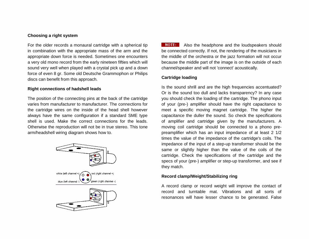
Right connections of hadshell leads
The position of the connecting pins at the back of the cartridge
varies from manufacturer to manufacturer. The connections for
the cartridge wires on the inside of the head shell however
always have the same configuration if a standard SME type
shell is used. Make the correct connections for the leads.
Otherwise the reproduction will not be in true stereo. This tone
arm/headshell wiring diagram shows how to.
Also the headphone and the loudspeakers should
be connected correctly. If not, the rendering of the musicians in
the middle of the orchestra or the jazz formation will not occur
because the middle part of the image is on the outside of each
channel/speaker and will not 'connect' acoustically.
Cartridge loading
Is the sound shrill and are the high frequencies accentuated?
Or is the sound too dull and lacks transparency? In any case
you should check the loading of the cartridge. The phono input
of your (pre-) amplifier should have the right capacitance to
meet a specific moving magnet cartridge. The higher the
capacitance the duller the sound. So check the specifications
of amplifier and cartridge given by the manufacturers. A
moving coil cartridge should be connected to a phono pre-
preamplifier which has an input impedance of at least 2 1/2
times the value of the impedance of the cartridge's coils. The
impedance of the input of a step-up transformer should be the
same or slightly higher than the value of the coils of the
cartridge. Check the specifications of the cartridge and the
specs of your (pre-) amplifier or step-up transformer, and see if
they match.
Record clamp/Weight/Stabilizing ring
A record clamp or record weight will improve the contact of
record and turntable mat. Vibrations and all sorts of
resonances will have lesser chance to be generated. False

high frequencies will not occur. The overall signal will be more
precise and the sound will have less distortion.
Avoid acoustical and mechanical feedback
If you live in a house/apartment with concrete floors, you can
use an audio rack with spikes to support your turntable. If you
want a good coupling make small holes in the carpet and place
the spikes directly on the concrete.
Take care of your records
To get the best quality of reproduction it is imperative to take
care of the records. That is why records need cleaning from
time to time. If you do not have access to a professional Keith
Monks Record Cleaning Machine, which provides the most
efficient way to safely clean records, you can buy a DISCO
ANTISTAT, with which you bathe and brush the two sides of
the record and then let the record dry. After cleaning and
drying put each and every record in a clean inner sleeve. If you
are handy you also can repair the covers to a certain extend
and also clean them.
WARNING
Electrical hazard! Misuse or failure to follow instructions properly may result in personal injury or death!
CAUTION
No risk or personal injury; however, misuse or failure to follow instructions may result in damage to equipment.
NOTE
No risk or personal injury or equipment damage; however, misuse or failure to follow instructions may prevent proper performance of the equipment.

Characteristics
Platter weight…………………………………………….…5 kg
Motor…………………………..asynchronous motor, 250 rpm
Weight……………………………………………………….8 kg
Dimentions (height, width, depth)…………15 cm, 52 cm, 41 cm
LIMITED WARRANTY
What is covered and what is Not Covered
Except as specified below, this warranty covers parts and labor to correct all defects in materials and workmanship. The following are not covered by the warranty:
1. Damage, deterioration, malfunction or failure to meet performance specifications resulting from:
a. Accident, acts of nature, misuse, abuse, neglect or unauthorized product modifications
b. Improper installation, removal or maintenance, or failure to follow instructions supplied with the product.
c. Repair or attempted repair by anyone not authorized by Margules Audio to repair the product.
d. Any shipment of the product (claims must be presented to the carrier).
e. Any cause other than a product defect.
2. Cleaning, initial set-up, check-ups with no defects found, or charges incurred for installation, removal or reinstallation of the product.

3. Any product, on which the serial number has been defaced, modified or removed.
4. Accessories, including but not limited to, batteries, cables, mounting hardware and brackets, cleaning accessories, antenna and detachable power cords.
5. Warranty is void if purchase was made from anyone other than an authorized Margules Audio dealer.
Who May Enforce the Warranty?
This warranty extends to products purchased directly from Margules Audio or an authorized Margules Audio dealer. Purchasers should inquire of the dealer regarding the nature and extent of the dealer’s warranty, if any.
What Will We Pay For?
We will pay for all labor and material expenses for items covered by the warranty. Payment of shipping charges is discussed in the next section of this warranty
How You Can Get Service?
In the event that the owner needs to return the unit to Margules Audio for service or repair of a possible defect, he must do the following:
Contact Margules Audio at (525) 514 7448 in Mexico or at 707-5811830 in USA and ask for technical support.
Or visit Margules Audio at the address in the end of this manual with your product. If you want to send it the cost is on your account.
Limitation of Implied Warranties
All implied warranties, including warranties of merchantability and fitness for particular purchase, are limited in duration to the length of this warranty.
Exclusion of Damages
Margules Audio’s liability for any defective product is limited to repair or replacement of the product at Margules Audio’s option. Margules Audio shall not be liable for damage to other products caused by any defects in Margules Audio products, damages based upon inconvenience or loss of use of the product, or any other damages, whether incidental, consequential, or otherwise.
How State Law Relates to the Warranty
Some states do not allow limitations on how long an implied warranty lasts and/or do not allow the exclusion or limitation of incidental or consequential damages, so the above limitations or exclusions may not apply to you.

This warranty gives you specific legal rights, and you may also have other rights which vary from state to state.
MARGULES GROUP MEXICO SA DE CV Uruapan #17-4, Col. Roma
Mexico D.F. 06700 Mexico.
Tel. (525) 514 7448 Toll free 1-888-538 8605
FAX (525)533 4654 Email: [email protected]
MARGULES USA 820 Elm Drive/div. PetalumaCA, 94952
Phone number: 707-5811830
Collect USA & Canada:
1-888-538 8605 Fax number: 707-5811830
Visit our home page in internet:
http://www.margules.com