Embed Size (px)
Citation preview

W
HI
TE
P
AP
ER
Proposal for a DfX process maturity
framework
Version 1.0 February 2011
Turning designs into reality:
The Manufacturability paradigm
Version 1.0
May, 2012

2
Getting ready for PLM
Copyright Notice
© Geometric Limited. All rights reserved.
No part of this document (whether in hardcopy or electronic form) may be reproduced, stored in a retrieval
system, or transmitted, in any form or by any means, electronic, mechanical, photocopying, recording, or
otherwise, to any third party without the written permission of Geometric Limited. Geometric Limited
reserves the right to change the information contained in this document without prior notice.
The names or trademarks or registered trademarks used in this document are the sole property of the
respective owners and are governed/ protected by the relevant trademark and copyright laws.
This document is provided by Geometric Limited for informational purposes only, without representation or
warranty of any kind, and Geometric Limited shall not be liable for errors or omissions with respect to the
document. The information contained herein is provided on an “AS-IS” basis and to the maximum extent
permitted by applicable law, Geometric Limited hereby disclaims all other warranties and conditions, either
express, implied or statutory, including but not limited to, any (if any) implied warranties, duties or
conditions of merchantability, of fitness for a particular purpose, of accuracy or completeness of responses,
of results, of workmanlike effort, of lack of viruses, and of lack of negligence, all with regard to the
document.
THERE IS NO WARRANTY OR CONDITION OF NON-INFRINGEMENT OF ANY INTELLECTUAL PROPERTY RIGHTS
WITH REGARD TO THE DOCUMENT. IN NO EVENT WILL GEOMETRIC LIMITED BE LIABLE TO ANY OTHER
PARTY FOR LOST PROFITS, LOSS OF USE, LOSS OF DATA, OR ANY INCIDENTAL, CONSEQUENTIAL, DIRECT,
INDIRECT, OR SPECIAL DAMAGES WHETHER UNDER CONTRACT, TORT, WARRANTY, OR OTHERWISE,
ARISING IN ANY WAY OUT OF THIS DOCUMENT, WHETHER OR NOT SUCH PARTY HAD ADVANCE NOTICE OF
THE POSSIBILITY OF SUCH DAMAGES.
Confidentiality Notice
This document is disclosed only to the recipient pursuant to a confidentiality relationship under which the
recipient has confidentiality obligations defined herein after. This document constitutes confidential
information and contains proprietary information belonging to Geometric Limited, and the recipient, by its
receipt of this document, acknowledges the same. The recipient shall use the confidential information only
for the purpose defined above for which this document is supplied. The recipient must obtain Geometric
Limited’s written consent before the recipient discloses any information on the contents or subject matter
of this document or part thereof to any third party which may include an individual, firm or company or an
employee or employees of such a firm or company. The recipient acknowledges its obligation to comply
with the provisions of this confidentiality notice.
3
Getting ready for PLM
Contents
Design Impact on Cost, Quality and Schedule ........................................................ 4
Design for Manufacturability .................................................................................. 4
Create improved designs for manufacturing .......................................................... 7
Design based on organizational and global best practices ..................................... 8
Benefits ................................................................................................................... 8
References .............................................................................................................. 9
About the Author .................................................................................................... 9
About Geometric .................................................................................................... 9

4
Getting ready for PLM
Design Impact on Cost, Quality and Schedule
Various studies have proven that an error detected and rectified during the design stage costs
almost a hundred to thousand times less than when rectified at manufacturing or further
downstream stages. Research also indicates that around 70% of the product cost is committed
during the design stage itself. Handling possible manufacturing problems during the design stage
is important because the impact is not only on time, but also on cost and quality. For example, a
non-standard hole detected during machining impacts the schedule if the design has to be
reworked upon. If a non-standard tool has to be procured for machining, it leads to increased
cost. Thick ribs and non-uniform walls can lead to sink marks and other quality problems in
plastics components. If such defects are detected during inspection, it leads to scrap and rework,
thus affecting both time and cost. Defective products being shipped into the market have a high
and long term impact on the brand value of the company. Hence, it is important to ensure that
designs released downstream for manufacturing and assembly meet the organizational
standards and global best practices. This goes a long way in helping the organization stay
competitive, profitable and improve its brand image in the market.
Figure 1: Design Impact
Design for Manufacturability
‘Design for Manufacturability’ or 'Design for Manufacturing' (DFM) is a methodology that
involves designing with intent to minimize the cost of production and time-to-market, without
compromising on the quality of the product.
Eli Whitney can be credited with the application of a process involving DFM practices many years
before the origin of the term. A book, Metals Engineering Processes, edited by Roger Bolz and
published by ASME in 1958, provided guidelines for assisting designers in enhancing the
manufacturability of their designs. The term, DFM though became popular only around 1985.

5
Getting ready for PLM
Organizations have been practicing DFM mainly by maintaining DFM handbooks, periodically
training design engineers for latest manufacturing practices, and conducting design reviews. To
create good designs, which can be manufactured with ease, the primary tool is a good CAD
system. A crucial accompanying tool is a virtual design assistant for DFM. Creo Parametric from
PTC® and DFMPro from Geometric form such a pair of tools in the designers' toolkit, which allow
them freedom and flexibility to create innovative designs; at the same time ensures that the
recommended manufacturing guidelines are respected. This results in better designs for
manufacturing and assembly.
Figure 2 : DFMPro for Creo Parametric
Depending on the manufacturing process, the design engineer can ensure that the design is
suitable for production. For example, plastic parts should have uniform walls and features like
ribs and bosses for strengthening and fastener insertion respectively, while machined parts may
have features like holes, pockets and slots. Creo Parametric allows designers to innovate and
create designs using a variety of features, like extrude, revolve, pattern, rib, round, chamfer, hole,
etc.
Figure 3 : Creo Parametric Design Features

6
Getting ready for PLM
DFMPro allows users to verify if the created design is in accordance with organizational
manufacturing guidelines or standards. The organizational standards can be captured as a set of
rules or checks, which can be quickly verified during design. One of the significant advantages of
DFMPro is that it can identify manufacturing features of the model directly from the final
geometry. This means that one may design a hole as a revolve, or a cut-extrude, or a hole
feature; DFMPro identifies the manufacturing intent and then checks the feature for ease of
manufacturing. This frees the designer to use his choice of feature, the one he is most
comfortable with while working with Creo Parametric. Not only can the design engineer work on
a new model but using Creo's interoperability function, it is possible to work with a variety of
CAD models as a starting design. Even designs created or updated using Creo Direct and brought
into Creo Parametric or modified using Flexible Modeling Extension can be analyzed using
DFMPro.
As the design evolves with addition of every feature, Creo helps in building the design quickly,
while DFMPro validates the manufacturability at the click of a button. It supports checks for a
variety of manufacturing processes, including machining, sheet metal fabrication, injection
molding and assembly. Any modifications to the design required for improving manufacturability
are shown to the designer within the Creo environment itself.
Figure 4 : DFMPro validation result highlighted in Creo Parametric
7
Getting ready for PLM
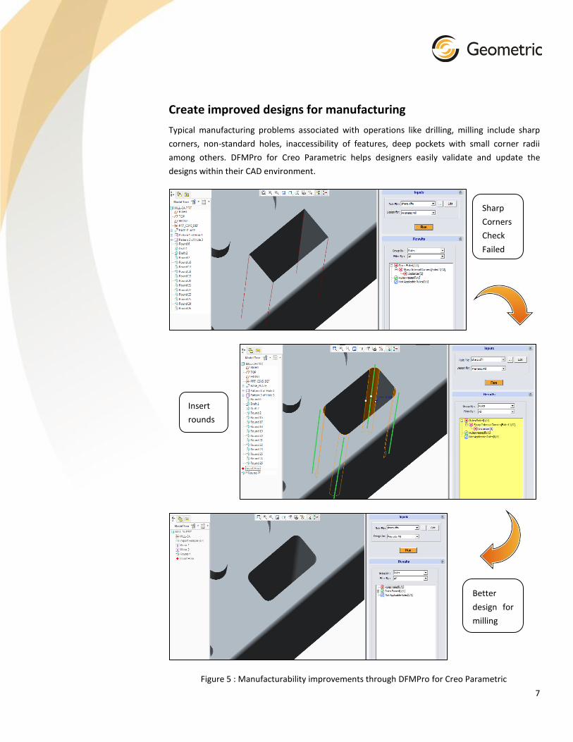
Create improved designs for manufacturing
Typical manufacturing problems associated with operations like drilling, milling include sharp
corners, non-standard holes, inaccessibility of features, deep pockets with small corner radii
among others. DFMPro for Creo Parametric helps designers easily validate and update the
designs within their CAD environment.
Figure 5 : Manufacturability improvements through DFMPro for Creo Parametric
Sharp
Corners
Check
Failed
Insert
rounds
Better
design for
milling
8
Getting ready for PLM
Similar to machining, typical problems in plastic designs include non-uniform walls, thick/tall ribs,
sharp corners, etc. Sheet metal fabrication poses problems when holes are too close to bends or
to each other, or when bend radius is not adequate, among others. Failure to check for assembly
requirements like component clearance, fastener engagement length, fastener clearance, hole
alignment can also lead to problems during assembly or operation. DFMPro can help easily
detect all these issues, and effortlessly update the designs using Creo.
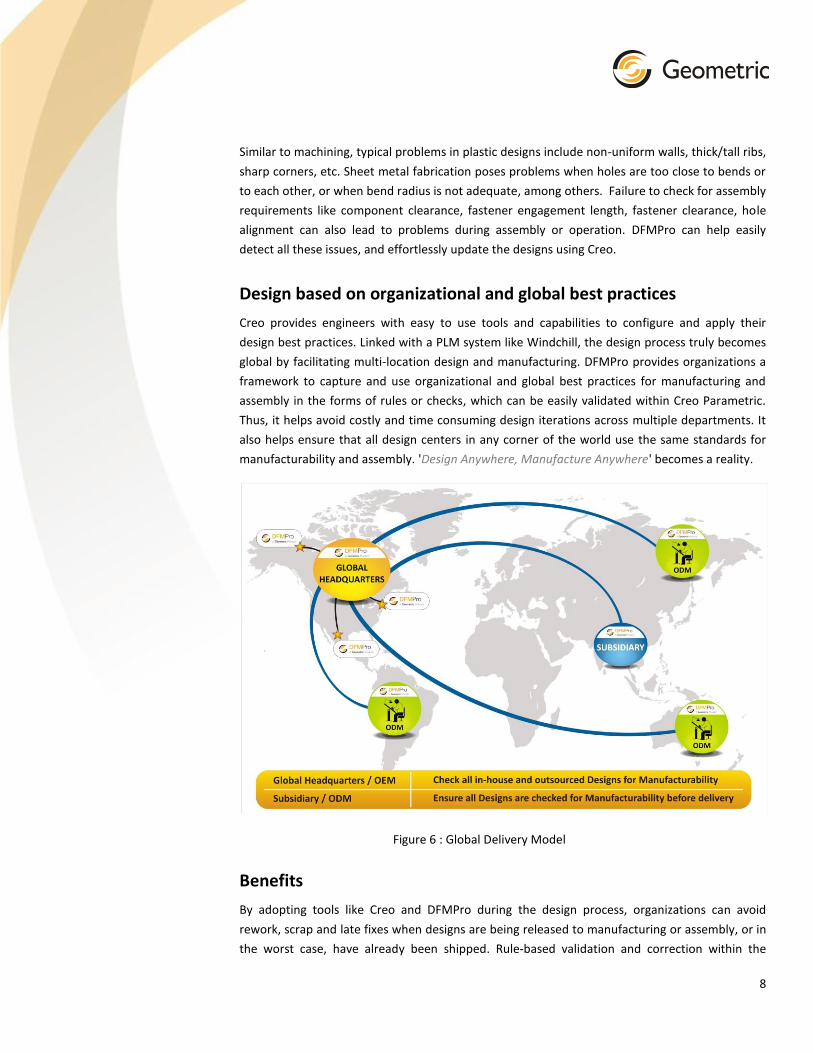
Design based on organizational and global best practices
Creo provides engineers with easy to use tools and capabilities to configure and apply their
design best practices. Linked with a PLM system like Windchill, the design process truly becomes
global by facilitating multi-location design and manufacturing. DFMPro provides organizations a
framework to capture and use organizational and global best practices for manufacturing and
assembly in the forms of rules or checks, which can be easily validated within Creo Parametric.
Thus, it helps avoid costly and time consuming design iterations across multiple departments. It
also helps ensure that all design centers in any corner of the world use the same standards for
manufacturability and assembly. 'Design Anywhere, Manufacture Anywhere' becomes a reality.
Figure 6 : Global Delivery Model
Benefits
By adopting tools like Creo and DFMPro during the design process, organizations can avoid
rework, scrap and late fixes when designs are being released to manufacturing or assembly, or in
the worst case, have already been shipped. Rule-based validation and correction within the

9
Getting ready for PLM
design environment can save designers, hundreds of hours in repetitive tasks and rework. A rules
based process linked to the CAD environment ensures that documented standard and guidelines
are embedded in software, reusable, easy to update and form part of the design cycle.
References
Bralla James G., Design For Manufacturability Handbook, Second Edition
Poli C., Design for Manufacturing: A Structured Approach
www.dfmpro.com
http://www.ptc.com/products/creo/
About the Author
Rahul Rajadhyaksha is Product Manager for DFMPro, an easy-to-use Design for Manufacturability (DFM)
tool developed by Geometric for design and manufacturing engineers. Rahul is a mechanical engineer and
has CAD/CAM product development and product management experience of over eleven years.
About Geometric
Geometric is a specialist in the domain of engineering solutions, services and technologies. Its
portfolio of Global Engineering services and Digital Technology solutions for Product Lifecycle
Management (PLM) enables companies to formulate, implement, and execute global engineering
and manufacturing strategies aimed at achieving greater efficiencies in the product realization
lifecycle.
Geometric’s Geometry Technology Solutions (GTS) business unit develops cutting-edge point
productivity solutions that enhance design and improve manufacturing operations. The end-user
products from Geometric include CAMWorks®, eDrawings® Publisher, DFMPro, GeomCaliper®,
3DPaintBrush™ and Glovius®. The key technologies from Geometric are NestLib®, Feature
Recognition (FR), GeomDiff and 3DSearchIT®. Geometric licenses these technologies to OEM
partners and also designs and implements customized process solutions using these technologies
for industrial customers.
For further details about Geometric’s GTS business unit, please visit
www.geometricglobal.com/products or call +1.480.367.0132
The copyright/ trademarks of all products referenced herein are held by their respective
companies.