Embed Size (px)
Citation preview

Turnaround Manhour Norms
TURNAROUND
MANHOUR NORMS
Specific Turnaround man-hour norms for work carried out at the YOURE_COMPANY
production site. For the use of planning, work preparation and payment of work carried
out during regular maintenance shutdowns.
Editionxxxxx Page 1 of 106

Turnaround Manhour Norms
Trésviri Project Control BV
Published by Trésviri Project Control BV in order of YOURE_COMPANY
All rights reserved by YOURE_COMPANY
All rights reserved by YOURE_COMPANY
YOURE_COMPANY Turnaround Manhour Norms
All man-hour norms are carefully chosen. The user should make sure that the man-hours in this book
match the specific job that has to be carried out. The author is not liable for any costs resulting from
the use of these man-hour norms.
Nothing in this publication may be reproduced, stored in a database and / or published in any form or
Editionxxxxx Page 2 of 106

Turnaround Manhour Norms
Content
Editionxxxxx Page 3 of 106
Turnaround Manhour Norms
Content:GENERAL Page
Introduction 15
Multipliers (correction factors) 15
Preambles 16
Heat Exchangers - Columns - Airfin Coolers - Boilers
Multipliers (correction factors) 18
Other disciplines 18
Measurement 18
Columns
20A10 Demisters 19
20A20 t/m 20A22 Trays 20
20A30 Hatches in Columntrays 21
20A40 Snap-in Valves 21
20A50 Bubble-caps 21
20A60 Calming section 21
20A70 Steam or Spider ring 22
20A80 Vortex Breaker 23
Heat Exchangers
20B10 t/m 20B50 Remove and install parts 24
20B55 Debolt & bolt up Studbolts 24
20B60 Remove and install Pipe plug 24
20B65 Bundel pulling or installing With a Crane or selfproppelled 25
20B66 Bundel pulling or installing Manual 25
20B70 Connect or disconnect testpump 25
20B75 Bundel test, Shell side or Tube side 25
20B80 Cleaning flange face / 20B85 Refacing gasket / 20B90 Anodes 26
Airfin Coolers
20C10 2 Plenum Chamber Airfin Cooler 27
20C20 3 Plenum Chamber Airfin Cooler 27
20C30 Louvres 27
20C40 Pluges 28
20C50 Airfin Cooler Testing 28
Boilers
20D10 Hatches in Boilers 29
20D20 Fleu Gas flaps 30
Content
Editionxxxxx Page 4 of 106
Turnaround Manhour Norms
Piping & Mechanical Page
Multipliers (correction factors) 32
Other disciplines 32
Measurement 32
Piping
43A10.1 PIPEHANDLING (NEW) 33
43A10.2 PIPEHANDLING (DEMOLITION) 34
43A11.1 FLANGED PIPESPOOL Uninstall 35
43A11.2 FLANGED PIPESPOOL Installation 36
43A20.1 CUTTING PIPE (FLAME) 37
43A20.2 CUTTING PIPE (SAW) 38
Welding
43A30.1 BUTTWELD 39
43A30.2 SOCKETWELD 40
43A30.3 WELDING SO-FLANGE 41
43A30.4 OLETWELD 90 41
43A30.5 BRANCHWELD 90 Without Reinforcing Ring 42
43A30.6 BRANCHWELD 90 With Reinforcing Ring 43
43A30.7 BRANCHWELD 45 Without Reinforcing Ring 44
43A30.8 BRANCHWELD 45 With Reinforcing Ring 45
Flanged connections
43A40.1 REMOVAL of FLANGED CONNECTION 46
43A40.2 INSTALLATION of FLANGED CONNECTION 47
43A40.3 INSTALLATION of FLANGED CONNECTION (ROTABOLTS) 48
43A40.4 INSTALLATION of FLANGED CONNECTION(TORQUING) 49
43A50.1 REMOVAL of BLINDFLANGE, MAN- or HANDHOLE 50
43A50.2 INSTALLATION of BLINDFLANGE, MAN- or HANDHOLE 51
43A60.1 REMOVAL of SPADES 52
43A60.2 INSTALLATION of SPADES 53
Valves
43A70.1 REMOVAL of Manual operated VALVE 54
43A70.2 INSTALLATION of Manual operated VALVE 55
43A70.3 HANDLING of VALVE 56
43A70.4 OPEN AND CLOSE INSPECTION COVER 57
43A71.1 REMOVAL of Motor operated VALVE 58
43A71.2 INSTALLATION of Motor operated VALVE 59
43A72.1 REMOVAL of Safety VALVE 60
43A72.2 INSTALLATION of Safety VALVE 60
43A73.1 REMOVAL of Butterfly VALVE (wafer type only) 61
43A73.2 INSTALLATION of Butterfly VALVE (wafer type only) 61
43A74.1 REMOVAL of Filters/strainers 63
43A74.2 INSTALLATION of Filters/strainers 64
43A75.1 REMOVAL of DUAL valves / 3-way valves 65
43A75.2 INSTALLATION of DUAL valves / 3-way valves 65
43A76.1 REMOVAL of Level body's 66
43A76.2 INSTALLATION of Level body's 66
43A77.1 REMOVAL of Level indicators 67
43A77.2 INSTALLATION of Level indicators 67
Content
Editionxxxxx Page 5 of 106

Turnaround Manhour Norms
Piping & Mechanical Page
43A78.1 REMOVAL of Thermowell's 68
43A78.2 INSTALLATION of Thermowell's 68
43A79.1 REMOVAL of Orifice 69
43A79.2 INSTALLATION of Orifice 70
43A80.1 THREADED CONNECTION 71
43A85.1 BENDING of PIPE 71
43A90.1 TESTING of PIPE (connect testpump) 72
Content
Editionxxxxx Page 6 of 106
Turnaround Manhour Norms
Electrical & Intrumentation Page
Multipliers (correction factors) 74
Other disciplines 74
Measurement 74
Cables
45A01.10* Installing and securing cables in Cable trays, Ducts and basements75
45A01.15 Pulling cable in conduit with open bends 76
45A01.20 Underground cable installation 77
45A02.10 Connecting instrumentation cables screened or unscreened 78
45A02.15 Connecting Low Voltage cables screened or unscreened 79
45A03.15 Installing a connector on a fiber optic cable. 80
45A03.20 Welding fibers by crimping or fusion welding. 80
45A03.25 Fiber testing and test report 80
45A03.30 Connecting connectorised duplex fiber optic cable to equipment81
45A03.40 Bringing multicore cable into junction box 82
45A04.10 Installing Glands and Blind (Blanking) Glands 82
Earthing
45A05.10 Installing a Earthing bushbar or strip 83
45A05.15 Earthing: extension or branching using a connecting block or clamp.83
45A05.20 Installing a earth rod into the ground 83
45A05.25 Installing an auxiliary ground electrode into the ground 84
45A05.30 Installing a ground electrode inspection pit. 84
Cableladders, trays
45A06.10 Installation of conduit, cable ladders or cable trays 85
45A06.15 Installing fittings in cable ladders and cable trays 86
45A06.20 Installing cable trays on steel or concrete structures 86
45A06.25 Installing fittings for cable trays 87
45A06.30 Installing galvanized wire-type cable trays 87
Installation hook-ups
45A07.10 Complete installation Instrumentation 88
Figure 1 89
Figure 2 90
Figure 3 91
Figure 4 92
Impulse, air and supply lines
45A08.10 Installing Impulse, air and supply lines (L<3m / PVC coated copper)93
45A08.15 Installing Impulse, air and supply lines (L<3m / monel) 93
45A08.20 Installing Impulse, air and supply lines (L<3m / polymer) 94
45A08.25 Installing Impulse, air and supply lines (L<3m / CrNiMo / Inconel 825)94
45A08.30 Installing Impulse, air and supply lines (L>3m / PVC coated copper)95
45A08.35 Installing Impulse, air and supply lines (L>3m / monel) 95
45A08.40 Installing Impulse, air and supply lines (L>3m / polymer) 96
45A08.45 Installing Impulse, air and supply lines (L>3m / CrNiMo / Inconel 825)96
45A08.50 Installing a coupler 1/8" to 1/2" 97
Content
Editionxxxxx Page 7 of 106
Turnaround Manhour Norms
Wiring Page
45A09.10 Internal wiring 97
45A10.00 Cross Wiring 98
E & I Equipment Calibration & testing
45A11.10 Inspecting control valves, ON-OF valves and related Items 98
45A11.15 Differential Pressure transmitters (with capillary / membrane) 99
45A11.20 Pressure transmitter (with capillary / membrane) 99
45A11.25 Differential Pressure transmitter 100
45A11.35 Vortex meter 100
45A11.40 Temperature measurement elements 101
45A11.45 Level transmitter (in the field) 101
45A11.50 Level transmitter (in workshop) 101
45A11.55 Level magnetic 102
45A11.60 Replacement of a level indicator and adjusting the control 102
45A11.65 Level capacitive 102
45A11.70 Switches 103
45A11.75 Safeguarding Instruments 104
45A11.80 Configuring smart instruments 104
45A12.10 Terminal clamp 104
45A13.10 Testing electrical equipment 105
45A13.15 Motor test 105
45A13.20 Wiring test (Low Voltage Cables) 106
45A13.25 Wiring test (Instrument Cables) 106
45A13.30 Looptest 107
Heat tracing
45A16.10 Heat tracing (cable) 108
45A16.15 Heat tracing (fittings) 108
Temporary facilities
45A17.10 Temporary facilities 109
Equipment installation
45A18.10 Equipment Installation 109
45A19.10 Installing small equipment on an existing support 110
Content
Editionxxxxx Page 8 of 106
Turnaround Manhour Norms
Hot Insulation Page
Multipliers (correction factors) 112
Other disciplines 112
Measurement 112
Activity codes 113
46A10 HOT Insulation Pipe 114
Insulation Thickness 30mm
Insulation Thickness 40mm
Insulation Thickness 50mm
Insulation Thickness 60mm
Insulation Thickness 70mm
Insulation Thickness 80mm
Insulation Thickness 100mm
Insulation Thickness 120mm
Insulation Thickness 140mm
46A20 HOT Insulation Elbow 123
Insulation Thickness 30mm
Insulation Thickness 40mm
Insulation Thickness 50mm
Insulation Thickness 60mm
Insulation Thickness 70mm
Insulation Thickness 80mm
Insulation Thickness 100mm
Insulation Thickness 120mm
Insulation Thickness 140mm
46A30 HOT Insulation Reducer 132
Insulation Thickness 30mm
Insulation Thickness 40mm
Insulation Thickness 50mm
Insulation Thickness 60mm
Insulation Thickness 70mm
Insulation Thickness 80mm
Insulation Thickness 100mm
Insulation Thickness 120mm
Insulation Thickness 140mm
46A40 HOT Insulation Tee 141
Insulation Thickness 30mm
Insulation Thickness 40mm
Insulation Thickness 50mm
Insulation Thickness 60mm
Insulation Thickness 70mm
Insulation Thickness 80mm
Insulation Thickness 100mm
Insulation Thickness 120mm
Insulation Thickness 140mm
Content
Editionxxxxx Page 9 of 106
Turnaround Manhour Norms
Page
46A50 HOT Insulation Flange Cap 150
Insulation Thickness 30mm
Insulation Thickness 40mm
Insulation Thickness 50mm
Insulation Thickness 60mm
Insulation Thickness 70mm
Insulation Thickness 80mm
Insulation Thickness 100mm
Insulation Thickness 120mm
Insulation Thickness 140mm
46A60 HOT Insulation End Cap 159
Insulation Thickness 30mm
Insulation Thickness 40mm
Insulation Thickness 50mm
Insulation Thickness 60mm
Insulation Thickness 70mm
Insulation Thickness 80mm
Insulation Thickness 100mm
Insulation Thickness 120mm
Insulation Thickness 140mm
46A70 HOT Insulation Valve Cap 168
Insulation Thickness 30mm
Insulation Thickness 40mm
Insulation Thickness 50mm
Insulation Thickness 60mm
Insulation Thickness 70mm
Insulation Thickness 80mm
Insulation Thickness 100mm
Insulation Thickness 120mm
Insulation Thickness 140mm
46A80 HOT Insulation m2 Equipment 177
Insulation Thickness (See separate lines)
Content
Editionxxxxx Page 10 of 106
Turnaround Manhour Norms
COLD Insulation Page
46B10 COLD Insulation Pipe 179
Insulation Thickness 30mm
Insulation Thickness 40mm
Insulation Thickness 50mm
Insulation Thickness 50mm
Insulation Thickness 70mm
Insulation Thickness 80mm
Insulation Thickness 100mm
Insulation Thickness 120mm
Insulation Thickness 140mm
46B20 COLD Insulation Elbow 188
Insulation Thickness 30mm
Insulation Thickness 40mm
Insulation Thickness 50mm
Insulation Thickness 60mm
Insulation Thickness 70mm
Insulation Thickness 80mm
Insulation Thickness 100mm
Insulation Thickness 120mm
Insulation Thickness 140mm
46B30 COLD Insulation Reducer 197
Insulation Thickness 30mm
Insulation Thickness 40mm
Insulation Thickness 50mm
Insulation Thickness 60mm
Insulation Thickness 70mm
Insulation Thickness 80mm
Insulation Thickness 100mm
Insulation Thickness 120mm
Insulation Thickness 140mm
46B40 COLD Insulation Tee 206
Insulation Thickness 30mm
Insulation Thickness 40mm
Insulation Thickness 50mm
Insulation Thickness 60mm
Insulation Thickness 70mm
Insulation Thickness 80mm
Insulation Thickness 100mm
Insulation Thickness 120mm
Insulation Thickness 140mm
Content
Editionxxxxx Page 11 of 106
Turnaround Manhour Norms
Page
46B50 COLD Insulation Flange Cap 215
Insulation Thickness 30mm
Insulation Thickness 40mm
Insulation Thickness 50mm
Insulation Thickness 60mm
Insulation Thickness 70mm
Insulation Thickness 80mm
Insulation Thickness 100mm
Insulation Thickness 120mm
Insulation Thickness 140mm
46B60 COLD Insulation End Cap 224
Insulation Thickness 30mm
Insulation Thickness 40mm
Insulation Thickness 50mm
Insulation Thickness 60mm
Insulation Thickness 70mm
Insulation Thickness 80mm
Insulation Thickness 100mm
Insulation Thickness 120mm
Insulation Thickness 140mm
46B70 COLD Insulation Valve Cap 233
Insulation Thickness 30mm
Insulation Thickness 40mm
Insulation Thickness 50mm
Insulation Thickness 60mm
Insulation Thickness 70mm
Insulation Thickness 80mm
Insulation Thickness 100mm
Insulation Thickness 120mm
Insulation Thickness 140mm
46B80 COLD Insulation m2 Equipment 242
Insulation Thickness (See separate lines)
Content
Editionxxxxx Page 12 of 106
Turnaround Manhour Norms
Scaffolding Page
Multipliers (correction factors) 244
Other disciplines 244
Measurement 244
92A10.1 Independent standing scaffold Installation 244
92B10.1 Suspended / Bridging scaffold Installation 246
92C10.1 Cantilever scaffold Installation 249
92D10.1 Flooring Installation 251
92E10.1 Movable/rolling scaffold Installation 252
92F10.1 Staircase Installation 0-25 m3 253
92G10.1 Frost screens Installation 254
92H10.1 Frost screens detached Installation 255
92I10.1 Scaffolding tent Installation 256
92J10.1 Scaffolding covers Installation 257
92O10.1 Safety swing gate Installation 258
92Q10.1 Ladder entrance Installation 258
92R10.1 Safety-bar. Installation 258
Content
Editionxxxxx Page 13 of 106

Turnaround Manhour Norms
GENERAL
Editionxxxxx Page 14 of 106

Turnaround Manhour Norms
Introduction
Multipliers (correction factors)
- Safety requirements
- Work-permit procedure
- Average working height
- Distance between warehouses and work spot
- Daily cleaning of the working area (housekeeping)
- Working overtime and shift work
The purpose of this document is to provide guidance for developing and applying man-hour norms for
estimating work carried out during Turnarounds at the YOURE_COMPANY (YOURE_COMPANY)
production site. All Man-hour norms in this book where devised taking account of all the
circumstances on this location during a Turnaround.
All Man-hour norms in this book are based on DACE and UMS man-hour norms. All these norms were
recalculated for the specific YOURE_COMPANY Turnaround circumstances by using a multiplier.
This resulted in a new set of man-hour norms that cannot be queried on the basis of UMS and/or
DACE.
The Labour Standard levels are based on the work at the YOURE_COMPANY location (factor = 1.0
location /productivity), preparing Labour norms for other locations requires the application of location
(productivity) factors.
The following circumstances were included the man-hour norms:
All safety requirements of working at the YOURE_COMPANY Production Site, such as
Site introduction, H2S instructions etc.
Working in accordance with the YOURE_COMPANY work-permit instructions. This
involves checking the validity of the work permits at the construction site; testing the
construction site for the presence of gases and flammable fluids.
Working on all common working heights at the YOURE_COMPANY site. All possible
options where included in a general working height multiplier.
The distance of the various warehouses on the YOURE_COMPANY location were
collected and included in a general multiplier. Containers with small stock parts such as
gaskets, bolts/nuts are placed near the work location on the ground floor.
Housekeeping is part of the man-hour norms.
Working overtime and/or shift work is added as a multiplier.
General
Editionxxxxx Page 15 of 106

Turnaround Manhour Norms
- Displacement time
- Use of dust masks
- Normal interruptions of the work
- Working in full protective clothing
Time needed to go to the workplace and back. This is including impediments, differences
in heights, carrying hand tools and / or materials, making use of transport or not,
movements for personal care etc.
In some cases a dust mask is required. The man-hour norms are multiplied for those
situations.
In any work activity, disruptions may arise that are directly related to the work and are
practically impossible to avoid:
work methods, progress and job closure
tools
are multiplied for those situations.
In some cases full personal protective equipment is required. The man-hour norms are
multiplied for those situations.
If the use of breathing equipment is necessary, a correction factor of 1.50 may be applied to the
Labour Standard.
Preambles
The preambles (scope description) and qualifications (condition factors when special working
conditions apply) to the Labour norms are intended to provide the basis for completeness and
consistency. The preambles and qualifications apply to all types of installation work.
General
Editionxxxxx Page 16 of 106
Turnaround Manhour Norms
Airfin Coolers
Heat Exchangers
Columns
Boilers
Editionxxxxx Page 17 of 106

Turnaround Manhour Norms
Multipliers (correction factors)
working in enclosed spaces
working with personal protective equipment
working at height
Measurement
Heat Exchangers - Columns - Airfin Coolers - Boilers
Other disciplines
All items of work are measured net as fixed in position and no allowance is made in the quantities for
cut and waste
Supporting disciplines, such as scaffolding construction, insulation work, transport (unless stated
otherwise), lifting, Non Destructive testing, pre or post heating do not form part of the man-hour
norms.
The Labour norms take account of working conditions, such as:
Editionxxxxx Page 18 of 106
Turnaround Manhour Norms
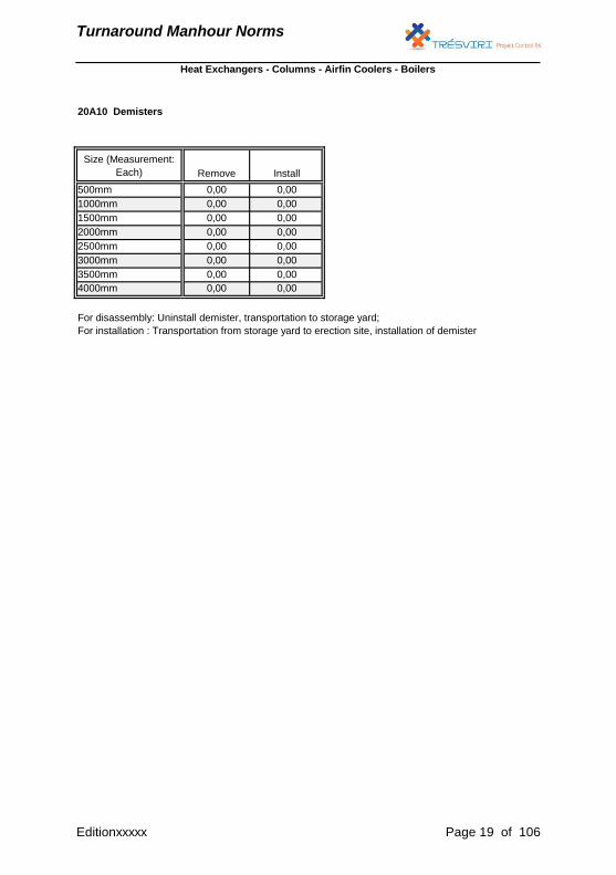
20A10 Demisters
500mm 0,00 0,00
1000mm 0,00
Install
Size (Measurement:
Each) Remove
Heat Exchangers - Columns - Airfin Coolers - Boilers
0,00
4000mm 0,00 0,00
2500mm 0,00 0,00
3000mm 0,00 0,00
1500mm 0,00 0,00
2000mm 0,00 0,00
For disassembly: Uninstall demister, transportation to storage yard;
For installation : Transportation from storage yard to erection site, installation of demister
3500mm 0,00 0,00
Editionxxxxx Page 19 of 106
Turnaround Manhour Norms
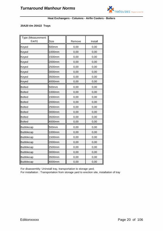
20A20 t/m 20A22 Trays
1000mm
0,00
Bolted 1500mm
0,00
0,00
Bolted 2000mm
0,00
Bolted
2500mm
Bubblecap 3000mm
Keyed 3500mm
Remove
Heat Exchangers - Columns - Airfin Coolers - Boilers
0,00
0,00
0,00
Bolted 500mm
0,00
Keyed 4000mm 0,00
Type (Measurement:
Each) Size
Keyed 2500mm
Keyed
3500mm
Bolted 4000mm
0,00
0,00
Bolted
3000mm
Keyed 1500mm
Keyed 2000mm
Keyed 500mm
Keyed 1000mm 0,00
0,00
0,00
0,00
0,00
0,00
0,00
0,00
0,00
0,00
0,00
0,00
Bubblecap 3500mm
Bubblecap 4000mm
0,00
0,00
0,00
0,00
0,00
0,00
0,00
0,00
0,00
Bubblecap 2000mm
Bubblecap
2500mm
0,00
Bolted 3000mm
0,00
0,00
0,00
0,00
Bubblecap 500mm
Bubblecap 1000mm
Bubblecap 1500mm
Bolted
0,00
0,00
0,00
Install
0,00
0,00
0,00
0,00
0,00
0,00
0,00
For disassembly: Uninstall tray, transportation to storage yard;
For installation : Transportation from storage yard to erection site, installation of tray
0,00
Editionxxxxx Page 20 of 106
Turnaround Manhour Norms
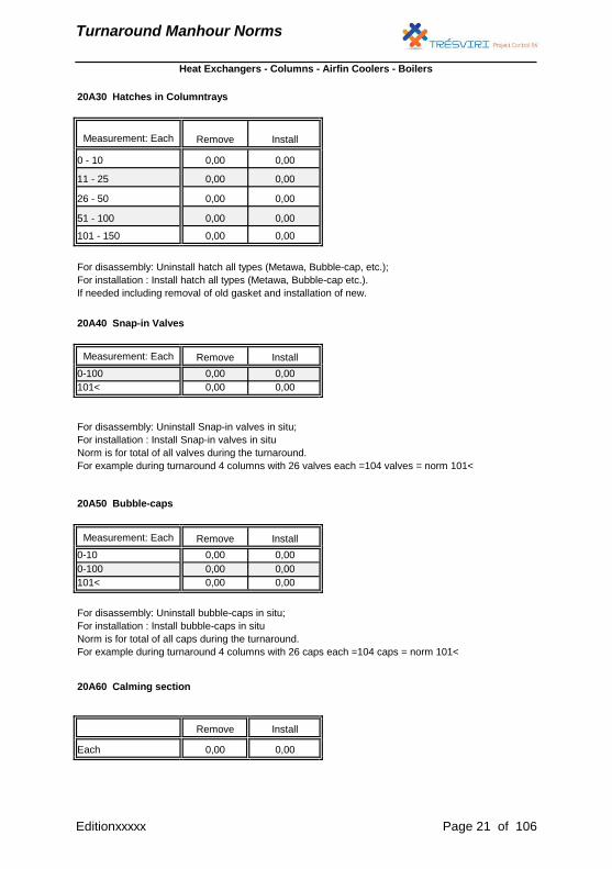
20A30 Hatches in Columntrays
20A40 Snap-in Valves
101<
20A50 Bubble-caps
0-10
101<
20A60 Calming section
Each
For disassembly: Uninstall hatch all types (Metawa, Bubble-cap, etc.);
For installation : Install hatch all types (Metawa, Bubble-cap etc.).
If needed including removal of old gasket and installation of new.
Measurement: Each Remove Install
0-100 0,00 0,00
0,00 0,00
26 - 50 0,00 0,00
0,00
0,00 0,00
For disassembly: Uninstall bubble-caps in situ;
For installation : Install bubble-caps in situ
Norm is for total of all caps during the turnaround.
For example during turnaround 4 columns with 26 caps each =104 caps = norm 101<
Heat Exchangers - Columns - Airfin Coolers - Boilers
Measurement: Each Remove Install
0 - 10 0,00 0,00
11 - 25 0,00 0,00
51 - 100 0,00 0,00
101 - 150 0,00 0,00
For disassembly: Uninstall Snap-in valves in situ;
For installation : Install Snap-in valves in situ
Norm is for total of all valves during the turnaround.
For example during turnaround 4 columns with 26 valves each =104 valves = norm 101<
0,00 0,00
0-100 0,00
0,00 0,00
Remove InstallMeasurement: Each
Remove Install
Editionxxxxx Page 21 of 106

Turnaround Manhour Norms
For disassembly: Uninstall Calming section;
For installation : Install calming section
Editionxxxxx Page 22 of 106
Turnaround Manhour Norms
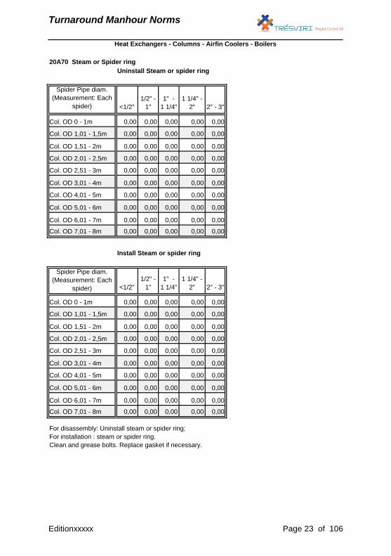
20A70 Steam or Spider ring
Uninstall Steam or spider ring
<1/2"
1/2" -
1"
1" -
1 1/4"
1 1/4" -
2" 2" - 3"
0,00 0,00 0,00 0,00 0,00
0,00 0,00 0,00 0,00 0,00
0,00 0,00 0,00 0,00 0,00
0,00 0,00 0,00 0,00 0,00
0,00 0,00 0,00 0,00 0,00
0,00 0,00 0,00 0,00 0,00
0,00 0,00 0,00 0,00 0,00
0,00 0,00 0,00 0,00 0,00
0,00 0,00 0,00 0,00 0,00
0,00 0,00 0,00 0,00 0,00
Install Steam or spider ring
<1/2"
1/2" -
1"
1" -
1 1/4"
1 1/4" -
2" 2" - 3"
0,00 0,00 0,00 0,00 0,00
0,00 0,00 0,00 0,00 0,00
0,00 0,00 0,00 0,00 0,00
0,00 0,00 0,00 0,00 0,00
0,00 0,00 0,00 0,00 0,00
0,00 0,00 0,00 0,00 0,00
0,00 0,00 0,00 0,00 0,00
0,00 0,00 0,00 0,00 0,00
0,00 0,00 0,00 0,00 0,00
0,00 0,00 0,00 0,00 0,00
Spider Pipe diam.
(Measurement: Each
spider)
Col. OD 5,01 - 6m
Col. OD 7,01 - 8m
Col. OD 0 - 1m
Col. OD 4,01 - 5m
Col. OD 6,01 - 7m
Col. OD 2,51 - 3m
Col. OD 3,01 - 4m
Col. OD 1,01 - 1,5m
Col. OD 1,51 - 2m
Col. OD 6,01 - 7m
Col. OD 7,01 - 8m
Heat Exchangers - Columns - Airfin Coolers - Boilers
For disassembly: Uninstall steam or spider ring;
For installation : steam or spider ring.
Clean and grease bolts. Replace gasket if necessary.
Spider Pipe diam.
(Measurement: Each
spider)
Col. OD 0 - 1m
Col. OD 1,01 - 1,5m
Col. OD 1,51 - 2m
Col. OD 2,01 - 2,5m
Col. OD 2,51 - 3m
Col. OD 3,01 - 4m
Col. OD 4,01 - 5m
Col. OD 5,01 - 6m
Col. OD 2,01 - 2,5m
Editionxxxxx Page 23 of 106
Turnaround Manhour Norms
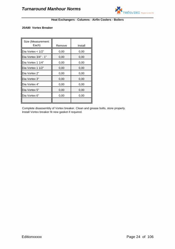
20A80 Vortex Breaker
Remove Install
0,00 0,00
0,00 0,00
0,00
0,00
0,00
Heat Exchangers - Columns - Airfin Coolers - Boilers
Size (Measurement:
Each)
Dia Vortex < 1/2"
Dia Vortex 3/4" - 1"
Dia Vortex 4"
Dia Vortex 5"
Dia Vortex 6"
0,00
0,00
Complete disassembly of Vortex breaker. Clean and grease bolts, store properly.
Install Vortex breaker fit new gasket if required.
Dia Vortex 1 1/4"
Dia Vortex 1 1/2"
Dia Vortex 2"
Dia Vortex 3" 0,00
0,00
0,00
0,00
0,00
0,00
0,00
0,00
0,00
Editionxxxxx Page 24 of 106
Turnaround Manhour Norms
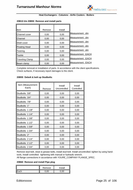
20B10 t/m 20B50 Remove and install parts
Measurement :dm
Measurement :dm
Measurement :dm
Measurement :dm
Measurement :dm
Measurement :EACH
Measurement :EACH
Measurement :EACH
20B55 Debolt & bolt up Studbolts
Studbolts 2 1/2"
Studbolts 2 3/4"
20B60 Remove and install Pipe plug
Each
Testring
Tackle
Heat Exchangers - Columns - Airfin Coolers - Boilers
0,00 0,00
Complete removal or installation of parts. In accordance with the client specifications.
Check surfaces, if necessary report damages to the client.
Item (Measurement:
Each)Install
Controlled
0,00
0,00
0,00
Remove
Install
Uncontrolled
Studbolts 5/8" 0,00 0,00
Studbolts 3/4" 0,00
0,00
0,00 0,00
0,00 0,00
0,00 0,00
0,00 0,00
Item
Channel cover
Channel
Shell cover
Floating Head
Traveling Clamp
Beam clamp
0,00
0,00
0,00
0,000,000,00Studbolts 1 5/8"
Studbolts 1" 0,00 0,00
Studbolts 1 1/8" 0,00 0,00
Studbolts 1 1/4" 0,00 0,00
0,00
Remove Install
0,00
0,00 0,00
0,00 0,00
Remove stud bolt, clean & grease bolts, install stud bolt. Install uncontrolled: tighten by using hand-
tools, Install controlled: tightening with manual or hydraulic wrench.
All flange connections in accordance with YOURE_COMPANY FLANGE_SPEC.
0,00 0,00 0,00
Remove Install
0,00 0,00
Studbolts 7/8" 0,00
0,000,000,00Studbolts 2 1/4"
0,000,000,00Studbolts 2"
0,000,000,00Studbolts 1 3/4"
Studbolts 1 3/8" 0,00 0,00
Studbolts 1 1/2" 0,00 0,00
0,00
0,00
0,00
0,00 0,00 0,00
Editionxxxxx Page 25 of 106

Turnaround Manhour Norms
Remove or install plug. Check surfaces, if necessary report damages to the client.
Editionxxxxx Page 26 of 106
Turnaround Manhour Norms
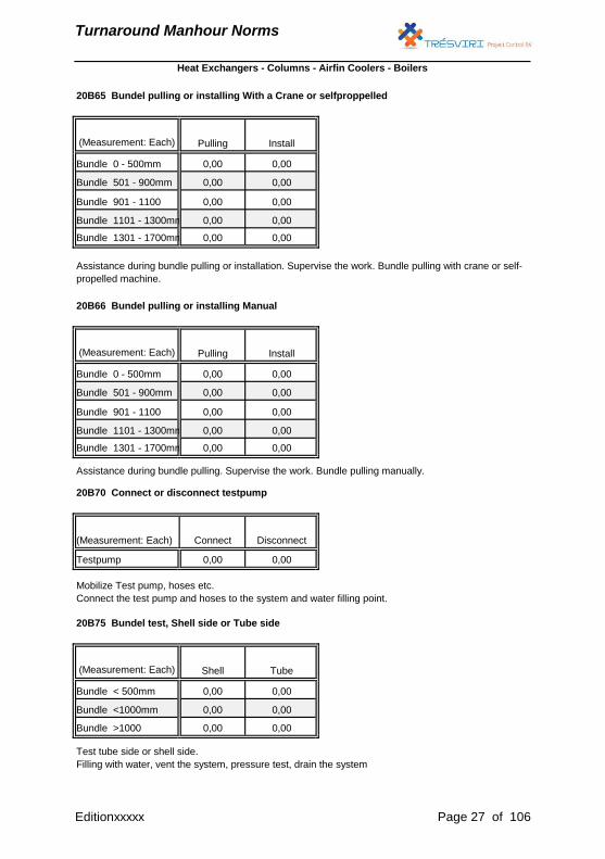
20B65 Bundel pulling or installing With a Crane or selfproppelled
20B66 Bundel pulling or installing Manual
20B70 Connect or disconnect testpump
20B75 Bundel test, Shell side or Tube side
0,00Bundle 1101 - 1300mm 0,00
(Measurement: Each) Pulling Install
Bundle 0 - 500mm 0,00 0,00
Bundle 1301 - 1700mm 0,00 0,00
Bundle 901 - 1100 0,00 0,00
Heat Exchangers - Columns - Airfin Coolers - Boilers
(Measurement: Each) Pulling Install
Bundle 0 - 500mm 0,00 0,00
Bundle 501 - 900mm 0,00 0,00
Bundle 1301 - 1700mm 0,00 0,00
Assistance during bundle pulling. Supervise the work. Bundle pulling manually.
(Measurement: Each) Shell Tube
Bundle 501 - 900mm 0,00 0,00
Bundle 901 - 1100 0,00 0,00
Bundle 1101 - 1300mm 0,00 0,00
Assistance during bundle pulling or installation. Supervise the work. Bundle pulling with crane or self-
propelled machine.
Test tube side or shell side.
Filling with water, vent the system, pressure test, drain the system
(Measurement: Each) Connect Disconnect
Testpump 0,00 0,00
Mobilize Test pump, hoses etc.
Connect the test pump and hoses to the system and water filling point.
Bundle < 500mm 0,00 0,00
Bundle <1000mm 0,00 0,00
Bundle >1000 0,00 0,00
Editionxxxxx Page 27 of 106
Turnaround Manhour Norms
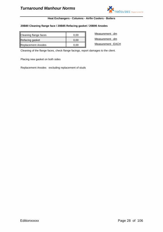
20B80 Cleaning flange face / 20B85 Refacing gasket / 20B90 Anodes
Cleaning flange facesMeasurement :dm
Measurement :dm
Measurement :EACH
0,00
Refacing gasket 0,00
Heat Exchangers - Columns - Airfin Coolers - Boilers
Replacement Anodes 0,00
Cleaning of the flange faces, check flange facings, report damages to the client.
Placing new gasket on both sides
Replacement Anodes excluding replacement of studs
Editionxxxxx Page 28 of 106
Turnaround Manhour Norms
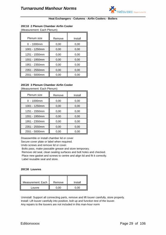
20C10 2 Plenum Chamber Airfin Cooler
(Measurement: Each Plenum)
20C20 3 Plenum Chamber Airfin Cooler
(Measurement: Each Plenum)
20C30 Louvres
1551 - 1950mm 0,00 0,00
2551 - 5000mm 0,00 0,00
0 - 1000mm 0,00 0,00
1001 - 1250mm 0,00 0,00
1251 - 1550mm 0,00 0,00
Heat Exchangers - Columns - Airfin Coolers - Boilers
Plenum size Remove Install
0 - 1000mm 0,00 0,00
1001 - 1250mm 0,00 0,00
1251 - 1550mm 0,00 0,00
1951 - 2350mm 0,00 0,00
2351 - 2550mm 0,00 0,00
Plenum size Remove Install
Louvre 0,00 0,00
2551 - 5000mm 0,00 0,00
Disassemble or install chamber lid or cover
Secure cover plate or label when required.
Undo screws and remove lid or cover.
Bolts pass, make passable grease and store temporary.
Remove old seal, clean sealing surfaces and bolt holes and checked.
Place new gasket and screws to centre and align lid and fit it correctly.
Label reusable seal and store.
Measurement: Each Remove Install
1551 - 1950mm 0,00 0,00
1951 - 2350mm 0,00 0,00
2351 - 2550mm 0,00 0,00
Uninstall: Support all connecting parts, remove and lift louver carefully, store properly.
Install: Lift louver carefully into position, bolt up and function test of the louver.
Any repairs to the louvers are not included in this man-hour norm
Editionxxxxx Page 29 of 106
Turnaround Manhour Norms
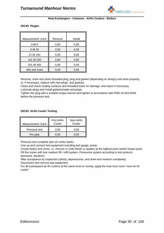
20C40 Pluges
20C50 Airfin Cooler Testing
Measurement: Each Remove Install
0 till 5 0,00 0,00
Pressure test complete (per air cooler bank)
Line up and connect test equipment including test gauge, pump.
Create drains and vents, i.e. remove or undo blinds or spades at the highest point and/or lowest point.
Fill the cooler with test medium fill / refill system. Pressurise system according to test protocol
(pressure, duration).
After acceptance by Inspection (client), depressurise, and drain test medium completely.
Disconnect and remove test equipment.
For all subsequent air-fin coolers at the same level or vicinity, apply the man-hour norm "next Air-fin
cooler"
Per pipe 0,00 0,00
Pressure test 0,00 0,00
201 till 400 0,00 0,00
400 and more 0,00 0,00
Remove, mark and clean threaded plug, plug and gasket (depending on design) and store properly,
or, if necessary, replace with new plugs and gaskets.
Clean and check sealing surfaces and threaded holes for damage, and report if necessary.
Lubricate plugs and install gaskets/seals and plugs.
Tighten the plug with a suitable torque wrench and tighten in accordance with PMS.16.023.WI03
before the pressure test.
Heat Exchangers - Columns - Airfin Coolers - Boilers
Measurement: Each
First Airfin
Cooler
Next Airfin
Cooler
6 till 20 0,00 0,00
21 till 100 0,00 0,00
101 till 200 0,00 0,00
Editionxxxxx Page 30 of 106
Turnaround Manhour Norms
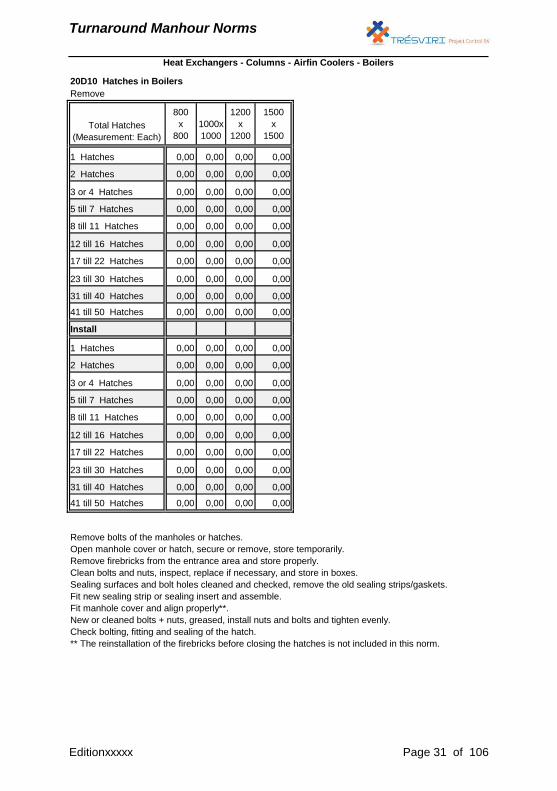
20D10 Hatches in Boilers
Remove
800
x
800
1000x
1000
1200
x
1200
1500
x
1500
0,00 0,00 0,00 0,00
0,00 0,00 0,00 0,00
0,00 0,00 0,00 0,00
0,00 0,00 0,00 0,00
0,00 0,00 0,00 0,00
0,00 0,00 0,00 0,00
0,00 0,00 0,00 0,00
0,00 0,00 0,00 0,00
0,00 0,00 0,00 0,00
0,00 0,00 0,00 0,00
0,00 0,00 0,00 0,00
0,00 0,00 0,00 0,00
0,00 0,00 0,00 0,00
0,00 0,00 0,00 0,00
0,00 0,00 0,00 0,00
0,00 0,00 0,00 0,00
0,00 0,00 0,00 0,00
0,00 0,00 0,00 0,00
0,00 0,00 0,00 0,00
0,00 0,00 0,00 0,00
Total Hatches
(Measurement: Each)
1 Hatches
Heat Exchangers - Columns - Airfin Coolers - Boilers
Install
1 Hatches
2 Hatches
3 or 4 Hatches
5 till 7 Hatches
8 till 11 Hatches
12 till 16 Hatches
23 till 30 Hatches
31 till 40 Hatches
41 till 50 Hatches
8 till 11 Hatches
12 till 16 Hatches
17 till 22 Hatches
2 Hatches
3 or 4 Hatches
5 till 7 Hatches
17 till 22 Hatches
23 till 30 Hatches
31 till 40 Hatches
41 till 50 Hatches
Remove bolts of the manholes or hatches.
Open manhole cover or hatch, secure or remove, store temporarily.
Remove firebricks from the entrance area and store properly.
Clean bolts and nuts, inspect, replace if necessary, and store in boxes.
Sealing surfaces and bolt holes cleaned and checked, remove the old sealing strips/gaskets.
Fit new sealing strip or sealing insert and assemble.
Fit manhole cover and align properly**.
New or cleaned bolts + nuts, greased, install nuts and bolts and tighten evenly.
Check bolting, fitting and sealing of the hatch.
** The reinstallation of the firebricks before closing the hatches is not included in this norm.
Editionxxxxx Page 31 of 106
Turnaround Manhour Norms
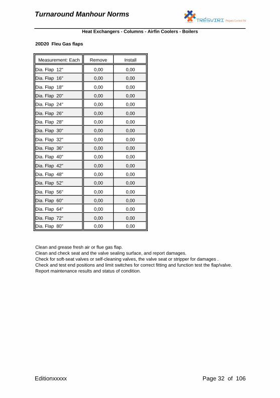
20D20 Fleu Gas flaps
Remove Install
0,00 0,00
0,00
0,00
0,00
0,00
0,00
0,00
0,00
0,00
0,00
0,00
0,00 0,00
Heat Exchangers - Columns - Airfin Coolers - Boilers
Measurement: Each
Dia. Flap 12"
Dia. Flap 16"
Dia. Flap 30" 0,00 0,00
Dia. Flap 32" 0,00 0,00
Dia. Flap 60" 0,00
0,00 0,00
Dia. Flap 48" 0,00 0,00
Dia. Flap 18"
Dia. Flap 20"
Dia. Flap 24"
Dia. Flap 26"
Dia. Flap 28"
0,00
Dia. Flap 36" 0,00 0,00
Dia. Flap 40" 0,00 0,00
Dia. Flap 42"
Dia. Flap 52" 0,00 0,00
Dia. Flap 56" 0,00 0,00
Clean and grease fresh air or flue gas flap.
Clean and check seat and the valve sealing surface, and report damages.
Check for soft-seat valves or self-cleaning valves, the valve seat or stripper for damages .
Check and test end positions and limit switches for correct fitting and function test the flap/valve.
Report maintenance results and status of condition.
Dia. Flap 64" 0,00 0,00
Dia. Flap 72" 0,00 0,00
Dia. Flap 80" 0,00 0,00
Editionxxxxx Page 32 of 106

Turnaround Manhour Norms
Piping
&
Mechanical
Editionxxxxx Page 33 of 106

Turnaround Manhour Norms
Multipliers (correction factors)
Measurement
Other disciplines
Supporting disciplines, such as scaffolding construction, insulation work, transport (unless stated
otherwise), lifting, Non Destructive testing, post weld heat treatment do not form part of the man-hour
norms.
All items of work are measured net as fixed in position and no allowance is made in the quantities for
cut and waste.
For a work item a “Unit of Measure” is defined in meters (m) length, the measurement shall be the
length measured along the central axis of the items.
Al activities are based on Carbon steel materials, for other material types you have to use the
multiplier for that specific material. This only applies to welding and cutting.
Piping & Mechanical
The Labour norms are based on working at the YOURE_COMPANY location. For work in a shop
condition you have to use the multiplier for shop work.
Editionxxxxx Page 34 of 106
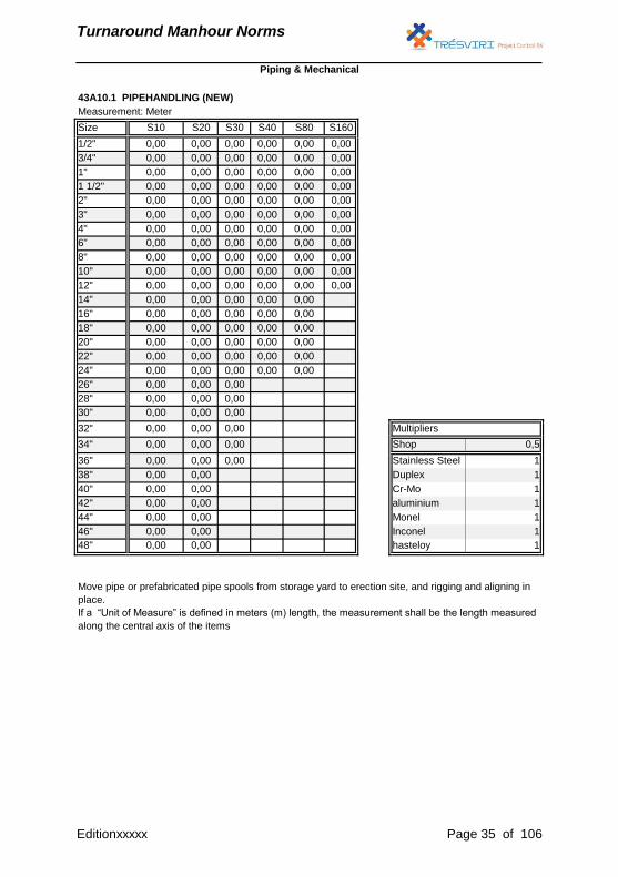
Turnaround Manhour Norms
Measurement: Meter
Size S10 S20 S30 S40 S80 S160
1/2" 0,00 0,00 0,00 0,00 0,00 0,00
3/4" 0,00 0,00 0,00 0,00 0,00 0,00
1" 0,00 0,00 0,00 0,00 0,00 0,00
1 1/2" 0,00 0,00 0,00 0,00 0,00 0,00
2" 0,00 0,00 0,00 0,00 0,00 0,00
3" 0,00 0,00 0,00 0,00 0,00 0,00
4" 0,00 0,00 0,00 0,00 0,00 0,00
6" 0,00 0,00 0,00 0,00 0,00 0,00
8" 0,00 0,00 0,00 0,00 0,00 0,00
10" 0,00 0,00 0,00 0,00 0,00 0,00
12" 0,00 0,00 0,00 0,00 0,00 0,00
14" 0,00 0,00 0,00 0,00 0,00
16" 0,00 0,00 0,00 0,00 0,00
18" 0,00 0,00 0,00 0,00 0,00
20" 0,00 0,00 0,00 0,00 0,00
22" 0,00 0,00 0,00 0,00 0,00
24" 0,00 0,00 0,00 0,00 0,00
26" 0,00 0,00 0,00
28" 0,00 0,00 0,00
30" 0,00 0,00 0,00
32" 0,00 0,00 0,00 Multipliers
34" 0,00 0,00 0,00 Shop 0,5
36" 0,00 0,00 0,00 Stainless Steel 1
38" 0,00 0,00 Duplex 1
40" 0,00 0,00 Cr-Mo 1
42" 0,00 0,00 aluminium 1
44" 0,00 0,00 Monel 1
46" 0,00 0,00 Inconel 1
48" 0,00 0,00 hasteloy 1
Move pipe or prefabricated pipe spools from storage yard to erection site, and rigging and aligning in
place.
If a “Unit of Measure” is defined in meters (m) length, the measurement shall be the length measured
along the central axis of the items
Piping & Mechanical
43A10.1 PIPEHANDLING (NEW)
Editionxxxxx Page 35 of 106

Turnaround Manhour Norms
Measurement: Meter
Size S10 S20 S30 S40 S80 S160
1/2" 0,00 0,00 0,00 0,00 0,00 0,00
3/4" 0,00 0,00 0,00 0,00 0,00 0,00
1" 0,00 0,00 0,00 0,00 0,00 0,00
1 1/2" 0,00 0,00 0,00 0,00 0,00 0,00
2" 0,00 0,00 0,00 0,00 0,00 0,00
3" 0,00 0,00 0,00 0,00 0,00 0,00
4" 0,00 0,00 0,00 0,00 0,00 0,00
6" 0,00 0,00 0,00 0,00 0,00 0,00
8" 0,00 0,00 0,00 0,00 0,00 0,00
10" 0,00 0,00 0,00 0,00 0,00 0,00
12" 0,00 0,00 0,00 0,00 0,00 0,00
14" 0,00 0,00 0,00 0,00 0,00
16" 0,00 0,00 0,00 0,00 0,00
18" 0,00 0,00 0,00 0,00 0,00
20" 0,00 0,00 0,00 0,00 0,00
22" 0,00 0,00 0,00 0,00 0,00
24" 0,00 0,00 0,00 0,00 0,00
26" 0,00 0,00 0,00
28" 0,00 0,00 0,00
30" 0,00 0,00 0,00
32" 0,00 0,00 0,00 Multipliers
34" 0,00 0,00 0,00 Shop 0,5
36" 0,00 0,00 0,00 Stainless Steel 1
38" 0,00 0,00 Duplex 1
40" 0,00 0,00 Cr-Mo 1
42" 0,00 0,00 aluminium 1
44" 0,00 0,00 Monel 1
46" 0,00 0,00 Inconel 1
48" 0,00 0,00 hasteloy 1
Piping & Mechanical
43A10.2 PIPEHANDLING (DEMOLITION)
Move pipe or demolished pipe spools from erection site to storage yard.
If a “Unit of Measure” is defined in meters (m) length, the measurement shall be the length measured
along the central axis of the items
Editionxxxxx Page 36 of 106
Turnaround Manhour Norms
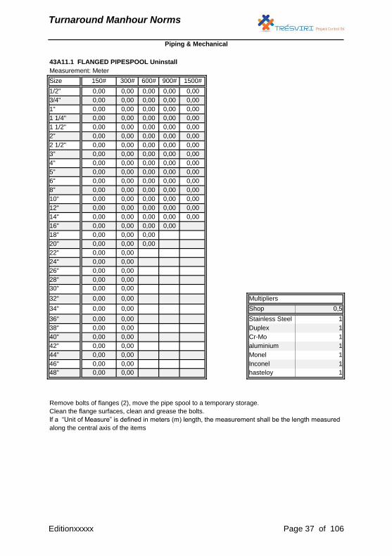
Measurement: Meter
Size 150# 300# 600# 900# 1500#
1/2" 0,00 0,00 0,00 0,00 0,00
3/4" 0,00 0,00 0,00 0,00 0,00
1" 0,00 0,00 0,00 0,00 0,00
1 1/4" 0,00 0,00 0,00 0,00 0,00
1 1/2" 0,00 0,00 0,00 0,00 0,00
2" 0,00 0,00 0,00 0,00 0,00
2 1/2" 0,00 0,00 0,00 0,00 0,00
3" 0,00 0,00 0,00 0,00 0,00
4" 0,00 0,00 0,00 0,00 0,00
5" 0,00 0,00 0,00 0,00 0,00
6" 0,00 0,00 0,00 0,00 0,00
8" 0,00 0,00 0,00 0,00 0,00
10" 0,00 0,00 0,00 0,00 0,00
12" 0,00 0,00 0,00 0,00 0,00
14" 0,00 0,00 0,00 0,00 0,00
16" 0,00 0,00 0,00 0,00
18" 0,00 0,00 0,00
20" 0,00 0,00 0,00
22" 0,00 0,00
24" 0,00 0,00
26" 0,00 0,00
28" 0,00 0,00
30" 0,00 0,00
32" 0,00 0,00 Multipliers
34" 0,00 0,00 Shop 0,5
36" 0,00 0,00 Stainless Steel 1
38" 0,00 0,00 Duplex 1
40" 0,00 0,00 Cr-Mo 1
42" 0,00 0,00 aluminium 1
44" 0,00 0,00 Monel 1
46" 0,00 0,00 Inconel 1
48" 0,00 0,00 hasteloy 1
Piping & Mechanical
43A11.1 FLANGED PIPESPOOL Uninstall
Remove bolts of flanges (2), move the pipe spool to a temporary storage.
Clean the flange surfaces, clean and grease the bolts.
If a “Unit of Measure” is defined in meters (m) length, the measurement shall be the length measured
along the central axis of the items
Editionxxxxx Page 37 of 106

Turnaround Manhour Norms
Measurement: Meter
Size 150# 300# 600# 900# 1500#
1/2" 0,00 0,00 0,00 0,00 0,00
3/4" 0,00 0,00 0,00 0,00 0,00
1" 0,00 0,00 0,00 0,00 0,00
1 1/4" 0,00 0,00 0,00 0,00 0,00
1 1/2" 0,00 0,00 0,00 0,00 0,00
2" 0,00 0,00 0,00 0,00 0,00
2 1/2" 0,00 0,00 0,00 0,00 0,00
3" 0,00 0,00 0,00 0,00 0,00
4" 0,00 0,00 0,00 0,00 0,00
5" 0,00 0,00 0,00 0,00 0,00
6" 0,00 0,00 0,00 0,00 0,00
8" 0,00 0,00 0,00 0,00 0,00
10" 0,00 0,00 0,00 0,00 0,00
12" 0,00 0,00 0,00 0,00 0,00
14" 0,00 0,00 0,00 0,00 0,00
16" 0,00 0,00 0,00 0,00
18" 0,00 0,00 0,00
20" 0,00 0,00 0,00
22" 0,00 0,00
24" 0,00 0,00
26" 0,00 0,00
28" 0,00 0,00
30" 0,00 0,00
32" 0,00 0,00 Multipliers
34" 0,00 0,00 Shop 0,5
36" 0,00 0,00 Stainless Steel 1
38" 0,00 0,00 Duplex 1
40" 0,00 0,00 Cr-Mo 1
42" 0,00 0,00 aluminium 1
44" 0,00 0,00 Monel 1
46" 0,00 0,00 Inconel 1
48" 0,00 0,00 hasteloy 1
Move the pipe spool into position, bolt-up flanges and place new gasket.
If a “Unit of Measure” is defined in meters (m) length, the measurement shall be the length measured
along the central axis of the items
Piping & Mechanical
43A11.2 FLANGED PIPESPOOL Installation
Editionxxxxx Page 38 of 106
Turnaround Manhour Norms
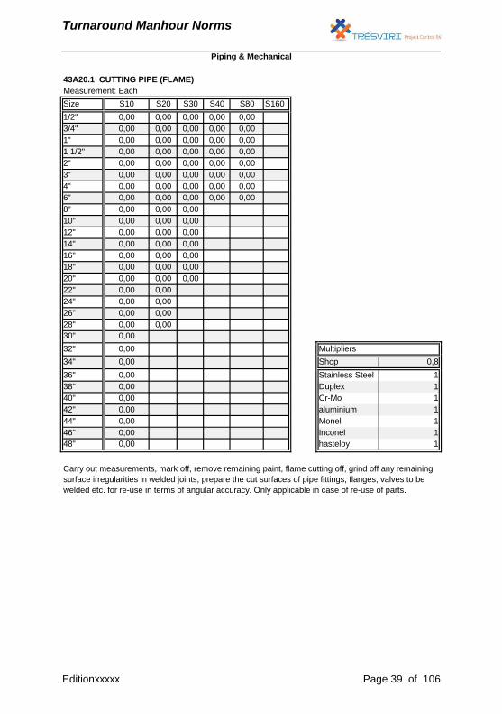
Measurement: Each
Size S10 S20 S30 S40 S80 S160
1/2" 0,00 0,00 0,00 0,00 0,00
3/4" 0,00 0,00 0,00 0,00 0,00
1" 0,00 0,00 0,00 0,00 0,00
1 1/2" 0,00 0,00 0,00 0,00 0,00
2" 0,00 0,00 0,00 0,00 0,00
3" 0,00 0,00 0,00 0,00 0,00
4" 0,00 0,00 0,00 0,00 0,00
6" 0,00 0,00 0,00 0,00 0,00
8" 0,00 0,00 0,00
10" 0,00 0,00 0,00
12" 0,00 0,00 0,00
14" 0,00 0,00 0,00
16" 0,00 0,00 0,00
18" 0,00 0,00 0,00
20" 0,00 0,00 0,00
22" 0,00 0,00
24" 0,00 0,00
26" 0,00 0,00
28" 0,00 0,00
30" 0,00
32" 0,00 Multipliers
34" 0,00 Shop 0,8
36" 0,00 Stainless Steel 1
38" 0,00 Duplex 1
40" 0,00 Cr-Mo 1
42" 0,00 aluminium 1
44" 0,00 Monel 1
46" 0,00 Inconel 1
48" 0,00 hasteloy 1
Carry out measurements, mark off, remove remaining paint, flame cutting off, grind off any remaining
surface irregularities in welded joints, prepare the cut surfaces of pipe fittings, flanges, valves to be
welded etc. for re-use in terms of angular accuracy. Only applicable in case of re-use of parts.
Piping & Mechanical
43A20.1 CUTTING PIPE (FLAME)
Editionxxxxx Page 39 of 106
Turnaround Manhour Norms
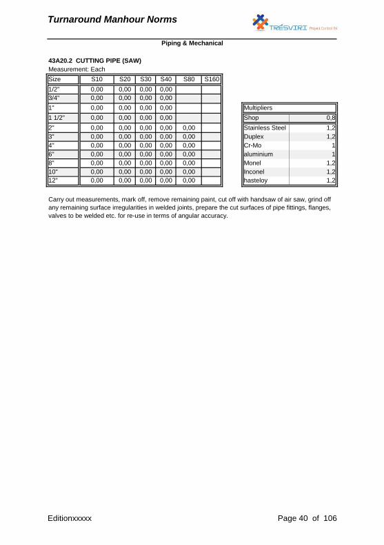
Measurement: Each
Size S10 S20 S30 S40 S80 S160
1/2" 0,00 0,00 0,00 0,00
3/4" 0,00 0,00 0,00 0,00
1" 0,00 0,00 0,00 0,00 Multipliers
1 1/2" 0,00 0,00 0,00 0,00 Shop 0,8
2" 0,00 0,00 0,00 0,00 0,00 Stainless Steel 1,2
3" 0,00 0,00 0,00 0,00 0,00 Duplex 1,2
4" 0,00 0,00 0,00 0,00 0,00 Cr-Mo 1
6" 0,00 0,00 0,00 0,00 0,00 aluminium 1
8" 0,00 0,00 0,00 0,00 0,00 Monel 1,2
10" 0,00 0,00 0,00 0,00 0,00 Inconel 1,2
12" 0,00 0,00 0,00 0,00 0,00 hasteloy 1,2
Carry out measurements, mark off, remove remaining paint, cut off with handsaw of air saw, grind off
any remaining surface irregularities in welded joints, prepare the cut surfaces of pipe fittings, flanges,
valves to be welded etc. for re-use in terms of angular accuracy.
Piping & Mechanical
43A20.2 CUTTING PIPE (SAW)
Editionxxxxx Page 40 of 106
Turnaround Manhour Norms
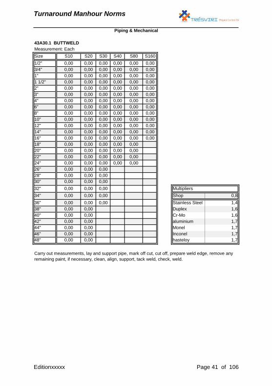
Measurement: Each
Size S10 S20 S30 S40 S80 S160
1/2" 0,00 0,00 0,00 0,00 0,00 0,00
3/4" 0,00 0,00 0,00 0,00 0,00 0,00
1" 0,00 0,00 0,00 0,00 0,00 0,00
1 1/2" 0,00 0,00 0,00 0,00 0,00 0,00
2" 0,00 0,00 0,00 0,00 0,00 0,00
3" 0,00 0,00 0,00 0,00 0,00 0,00
4" 0,00 0,00 0,00 0,00 0,00 0,00
6" 0,00 0,00 0,00 0,00 0,00 0,00
8" 0,00 0,00 0,00 0,00 0,00 0,00
10" 0,00 0,00 0,00 0,00 0,00 0,00
12" 0,00 0,00 0,00 0,00 0,00 0,00
14" 0,00 0,00 0,00 0,00 0,00 0,00
16" 0,00 0,00 0,00 0,00 0,00 0,00
18" 0,00 0,00 0,00 0,00 0,00
20" 0,00 0,00 0,00 0,00 0,00
22" 0,00 0,00 0,00 0,00 0,00
24" 0,00 0,00 0,00 0,00 0,00
26" 0,00 0,00 0,00
28" 0,00 0,00 0,00
30" 0,00 0,00 0,00
32" 0,00 0,00 0,00 Multipliers
34" 0,00 0,00 0,00 Shop 0,8
36" 0,00 0,00 0,00 Stainless Steel 1,4
38" 0,00 0,00 Duplex 1,6
40" 0,00 0,00 Cr-Mo 1,6
42" 0,00 0,00 aluminium 1,7
44" 0,00 0,00 Monel 1,7
46" 0,00 0,00 Inconel 1,7
48" 0,00 0,00 hasteloy 1,7
Carry out measurements, lay and support pipe, mark off cut, cut off, prepare weld edge, remove any
remaining paint, if necessary, clean, align, support, tack weld, check, weld.
Piping & Mechanical
43A30.1 BUTTWELD
Editionxxxxx Page 41 of 106
Turnaround Manhour Norms
Measurement: Each
Size S10 S20 S30 S40 S80 S160 Multipliers
1/2" 0,00 0,00 0,00 0,00 0,00 0,00 Shop 0,8
3/4" 0,00 0,00 0,00 0,00 0,00 0,00 Stainless Steel 1,4
1" 0,00 0,00 0,00 0,00 0,00 0,00 Duplex 1,6
1 1/2" 0,00 0,00 0,00 0,00 0,00 0,00 Cr-Mo 1,6
2" 0,00 0,00 0,00 0,00 0,00 0,00 aluminium 1,7
Monel 1,7
Inconel 1,7
hasteloy 1,7
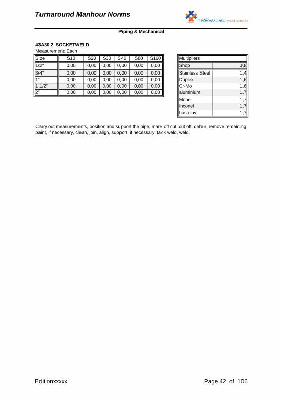
Carry out measurements, position and support the pipe, mark off cut, cut off, debur, remove remaining
paint, if necessary, clean, join, align, support, if necessary, tack weld, weld.
Piping & Mechanical
43A30.2 SOCKETWELD
Editionxxxxx Page 42 of 106
Turnaround Manhour Norms
Measurement: Each
Size All
1/2" 0,00
3/4" 0,00
1" 0,00
1 1/2" 0,00
2" 0,00
3" 0,00
4" 0,00
6" 0,00
8" 0,00 Multipliers
10" 0,00 Shop 0,8
12" 0,00 Stainless Steel 1,4
14" 0,00 Duplex 1,6
16" 0,00 Cr-Mo 1,6
18" 0,00 aluminium 1,7
20" 0,00 Monel 1,7
22" 0,00 Inconel 1,7
24" 0,00 hasteloy 1,7
Measurement: Each
Size S40 S80 Multipliers
1/2" 0,00 Shop 0,8
3/4" 0,00 Stainless Steel 1,4
1" 0,00 Duplex 1,6
1 1/2" 0,00 Cr-Mo 1,6
2" 0,00 0,00 aluminium 1,7
3" 0,00 0,00 Monel 1,7
4" 0,00 0,00 Inconel 1,7
6" 0,00 0,00 hasteloy 1,7
Piping & Mechanical
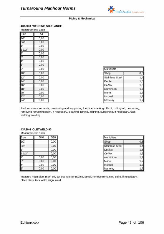
Perform measurements, positioning and supporting the pipe, marking off cut, cutting off, de-burring,
removing remaining paint, if necessary, cleaning, joining, aligning, supporting, if necessary, tack
welding, welding.
Measure main pipe, mark off, cut out hole for nozzle, bevel, remove remaining paint, if necessary,
place olets, tack weld, align, weld.
43A30.3 WELDING SO-FLANGE
43A30.4 OLETWELD 90
Editionxxxxx Page 43 of 106
Turnaround Manhour Norms
Measurement: Each
Size S10 S20 S30 S40 S80
1/2" 0,00 0,00 0,00 0,00 0,00
3/4" 0,00 0,00 0,00 0,00 0,00
1" 0,00 0,00 0,00 0,00 0,00
1 1/2" 0,00 0,00 0,00 0,00 0,00
2" 0,00 0,00 0,00 0,00 0,00
3" 0,00 0,00 0,00 0,00 0,00
4" 0,00 0,00 0,00 0,00 0,00
6" 0,00 0,00 0,00 0,00 0,00
8" 0,00 0,00 0,00 0,00 0,00
10" 0,00 0,00 0,00 0,00 0,00
12" 0,00 0,00 0,00 0,00 0,00
14" 0,00 0,00 0,00 0,00 0,00
16" 0,00 0,00 0,00 0,00 0,00
18" 0,00 0,00 0,00 0,00 0,00
20" 0,00 0,00 0,00 0,00 0,00
22" 0,00 0,00 0,00 0,00 0,00
24" 0,00 0,00 0,00 0,00 0,00
26" 0,00 0,00 0,00 0,00
28" 0,00 0,00 0,00 0,00
30" 0,00 0,00 0,00 0,00
32" 0,00 0,00 0,00 Multipliers
34" 0,00 0,00 0,00 Shop 0,8
36" 0,00 0,00 0,00 Stainless Steel 1,4
38" 0,00 0,00 Duplex 1,6
40" 0,00 0,00 Cr-Mo 1,6
42" 0,00 0,00 aluminium 1,7
44" 0,00 0,00 Monel 1,7
46" 0,00 0,00 Inconel 1,7
48" 0,00 0,00 hasteloy 1,7
Piping & Mechanical
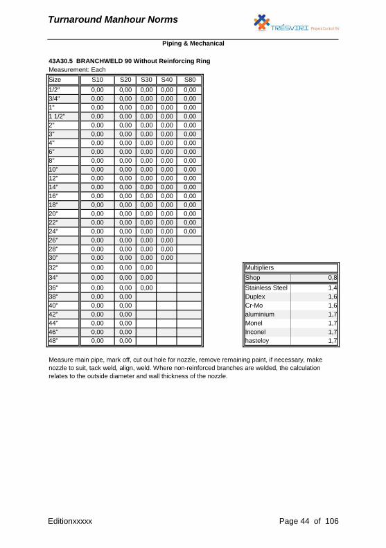
43A30.5 BRANCHWELD 90 Without Reinforcing Ring
Measure main pipe, mark off, cut out hole for nozzle, remove remaining paint, if necessary, make
nozzle to suit, tack weld, align, weld. Where non-reinforced branches are welded, the calculation
relates to the outside diameter and wall thickness of the nozzle.
Editionxxxxx Page 44 of 106

Turnaround Manhour Norms
Measurement: Each
Size S10 S20 S30 S40 S80
1/2"
3/4"
1"
1 1/2"
2" 0,00 0,00
3" 0,00 0,00
4" 0,00 0,00
6" 0,00 0,00
8" 0,00 0,00 0,00 0,00
10" 0,00 0,00 0,00 0,00
12" 0,00 0,00 0,00 0,00 Multipliers
14" 0,00 0,00 0,00 0,00 Shop 0,8
16" 0,00 0,00 0,00 0,00 Stainless Steel 1,4
18" 0,00 0,00 0,00 Duplex 1,6
20" 0,00 0,00 0,00 Cr-Mo 1,6
22" 0,00 0,00 aluminium 1,7
24" 0,00 0,00 Monel 1,7
26" 0,00 Inconel 1,7
28" 0,00 hasteloy 1,7
Piping & Mechanical
43A30.6 BRANCHWELD 90 With Reinforcing Ring
Measure main pipe, mark off, cut out hole for nozzle, remove remaining paint, if necessary, make
nozzle to suit, tack weld, align, weld. For reinforced branches, the outside diameter and the largest
nozzle wall thickness specified in the material take off are adhered to. Incl. penetrant examination if
required.
Editionxxxxx Page 45 of 106
Turnaround Manhour Norms
Measurement: Each
Size S10 S20 S30 S40 S80
1/2" 0,00 0,00 0,00 0,00 0,00
3/4" 0,00 0,00 0,00 0,00 0,00
1" 0,00 0,00 0,00 0,00 0,00
1 1/2" 0,00 0,00 0,00 0,00 0,00
2" 0,00 0,00 0,00 0,00 0,00
3" 0,00 0,00 0,00 0,00 0,00
4" 0,00 0,00 0,00 0,00 0,00
6" 0,00 0,00 0,00 0,00 0,00
8" 0,00 0,00 0,00 0,00 0,00
10" 0,00 0,00 0,00 0,00 0,00
12" 0,00 0,00 0,00 0,00 0,00
14" 0,00 0,00 0,00 0,00 0,00
16" 0,00 0,00 0,00 0,00 0,00
18" 0,00 0,00 0,00 0,00 0,00
20" 0,00 0,00 0,00 0,00 0,00
22" 0,00 0,00 0,00 0,00 0,00
24" 0,00 0,00 0,00 0,00 0,00
26" 0,00 0,00 0,00 0,00
28" 0,00 0,00 0,00 0,00
30" 0,00 0,00 0,00 0,00
32" 0,00 0,00 Multipliers
34" 0,00 0,00 Shop 0,8
36" 0,00 0,00 Stainless Steel 1,4
38" 0,00 0,00 Duplex 1,6
40" 0,00 0,00 Cr-Mo 1,6
42" 0,00 0,00 aluminium 1,7
44" 0,00 0,00 Monel 1,7
46" 0,00 0,00 Inconel 1,7
48" 0,00 0,00 hasteloy 1,7
Piping & Mechanical
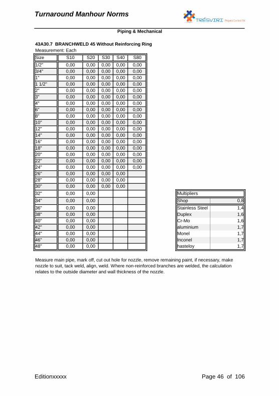
Measure main pipe, mark off, cut out hole for nozzle, remove remaining paint, if necessary, make
nozzle to suit, tack weld, align, weld. Where non-reinforced branches are welded, the calculation
relates to the outside diameter and wall thickness of the nozzle.
43A30.7 BRANCHWELD 45 Without Reinforcing Ring
Editionxxxxx Page 46 of 106
Turnaround Manhour Norms
Measurement: Each
Size S10 S20 S30 S40 S80
1/2"
3/4"
1"
1 1/2"
2" 0,00 0,00
3" 0,00 0,00
4" 0,00 0,00
6" 0,00 0,00
8" 0,00 0,00 0,00 0,00
10" 0,00 0,00 0,00 0,00
12" 0,00 0,00 0,00 0,00 Multipliers
14" 0,00 0,00 0,00 0,00 Shop 0,8
16" 0,00 0,00 0,00 Stainless Steel 1,4
18" 0,00 0,00 Duplex 1,6
20" 0,00 0,00 Cr-Mo 1,6
22" 0,00 0,00 aluminium 1,7
24" 0,00 0,00 Monel 1,7
26" 0,00 Inconel 1,7
28" 0,00 hasteloy 1,7
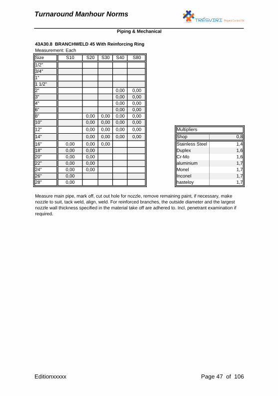
Measure main pipe, mark off, cut out hole for nozzle, remove remaining paint, if necessary, make
nozzle to suit, tack weld, align, weld. For reinforced branches, the outside diameter and the largest
nozzle wall thickness specified in the material take off are adhered to. Incl. penetrant examination if
required.
43A30.8 BRANCHWELD 45 With Reinforcing Ring
Piping & Mechanical
Editionxxxxx Page 47 of 106

Turnaround Manhour Norms
Measurement: Each
Size 150# 300# 600# 900# 1500# 2500#]
1/2" 0,00 0,00 0,00 0,00 0,00 0,00
3/4" 0,00 0,00 0,00 0,00 0,00 0,00
1" 0,00 0,00 0,00 0,00 0,00 0,00
1 1/2" 0,00 0,00 0,00 0,00 0,00 0,00
2" 0,00 0,00 0,00 0,00 0,00 0,00
3" 0,00 0,00 0,00 0,00 0,00 0,00
4" 0,00 0,00 0,00 0,00 0,00 0,00
6" 0,00 0,00 0,00 0,00 0,00 0,00
8" 0,00 0,00 0,00 0,00 0,00 0,00
10" 0,00 0,00 0,00 0,00 0,00 0,00
12" 0,00 0,00 0,00 0,00 0,00 0,00
14" 0,00 0,00 0,00 0,00 0,00
16" 0,00 0,00 0,00 0,00 0,00
18" 0,00 0,00 0,00 0,00 0,00
20" 0,00 0,00 0,00 0,00 0,00
22" 0,00 0,00 0,00 0,00 0,00
24" 0,00 0,00 0,00 0,00 0,00
26" 0,00 0,00 0,00
28" 0,00 0,00 0,00
30" 0,00 0,00 0,00
32" 0,00 0,00 0,00 Multipliers
34" 0,00 0,00 0,00 Shop 1
36" 0,00 0,00 0,00 Stainless Steel 1
38" 0,00 0,00 Duplex 1
40" 0,00 0,00 Cr-Mo 1
42" 0,00 0,00 aluminium 1
44" 0,00 0,00 Monel 1
46" 0,00 0,00 Inconel 1
48" 0,00 0,00 hasteloy 1
Debolt flange connection, clean bolts, removal of existing gasket, clean flange facings.
All flange connections in accordance with YOURE_COMPANY FLANGE_SPEC
43A40.1 REMOVAL of FLANGED CONNECTION
Piping & Mechanical
Editionxxxxx Page 48 of 106

Turnaround Manhour Norms
Measurement: Each
Size 150# 300# 600# 900# 1500# 2500#]
1/2" 0,00 0,00 0,00 0,00 0,00 0,00
3/4" 0,00 0,00 0,00 0,00 0,00 0,00
1" 0,00 0,00 0,00 0,00 0,00 0,00
1 1/2" 0,00 0,00 0,00 0,00 0,00 0,00
2" 0,00 0,00 0,00 0,00 0,00 0,00
3" 0,00 0,00 0,00 0,00 0,00 0,00
4" 0,00 0,00 0,00 0,00 0,00 0,00
6" 0,00 0,00 0,00 0,00 0,00 0,00
8" 0,00 0,00 0,00 0,00 0,00 0,00
10" 0,00 0,00 0,00 0,00 0,00 0,00
12" 0,00 0,00 0,00 0,00 0,00 0,00
14" 0,00 0,00 0,00 0,00 0,00
16" 0,00 0,00 0,00 0,00 0,00
18" 0,00 0,00 0,00 0,00 0,00
20" 0,00 0,00 0,00 0,00 0,00
22" 0,00 0,00 0,00 0,00 0,00
24" 0,00 0,00 0,00 0,00 0,00
26" 0,00 0,00 0,00
28" 0,00 0,00 0,00
30" 0,00 0,00 0,00
32" 0,00 0,00 0,00 Multipliers
34" 0,00 0,00 0,00 Shop 1
36" 0,00 0,00 0,00 Stainless Steel 1
38" 0,00 0,00 Duplex 1
40" 0,00 0,00 Cr-Mo 1
42" 0,00 0,00 aluminium 1
44" 0,00 0,00 Monel 1
46" 0,00 0,00 Inconel 1
48" 0,00 0,00 hasteloy 1
Bolt-up flange connection, grease bolts, install new gasket
All flange connections in accordance with YOURE_COMPANY FLANGE_SPEC
43A40.2 INSTALLATION of FLANGED CONNECTION
Piping & Mechanical
Editionxxxxx Page 49 of 106
Turnaround Manhour Norms
Measurement: Each
Size 150# 300# 600# 900# 1500# 2500#]
1/2" 0,00 0,00 0,00 0,00 0,00 0,00
3/4" 0,00 0,00 0,00 0,00 0,00 0,00
1" 0,00 0,00 0,00 0,00 0,00 0,00
1 1/2" 0,00 0,00 0,00 0,00 0,00 0,00
2" 0,00 0,00 0,00 0,00 0,00 0,00
3" 0,00 0,00 0,00 0,00 0,00 0,00
4" 0,00 0,00 0,00 0,00 0,00 0,00
6" 0,00 0,00 0,00 0,00 0,00 0,00
8" 0,00 0,00 0,00 0,00 0,00 0,00
10" 0,00 0,00 0,00 0,00 0,00 0,00
12" 0,00 0,00 0,00 0,00 0,00 0,00
14" 0,00 0,00 0,00 0,00 0,00
16" 0,00 0,00 0,00 0,00 0,00
18" 0,00 0,00 0,00 0,00 0,00
20" 0,00 0,00 0,00 0,00 0,00
22" 0,00 0,00 0,00 0,00 0,00
24" 0,00 0,00 0,00 0,00 0,00
26" 0,00 0,00 0,00
28" 0,00 0,00 0,00
30" 0,00 0,00 0,00
32" 0,00 0,00 0,00 Multipliers
34" 0,00 0,00 0,00 Shop 1
36" 0,00 0,00 0,00 Stainless Steel 1
38" 0,00 0,00 Duplex 1
40" 0,00 0,00 Cr-Mo 1
42" 0,00 0,00 aluminium 1
44" 0,00 0,00 Monel 1
46" 0,00 0,00 Inconel 1
48" 0,00 0,00 hasteloy 1
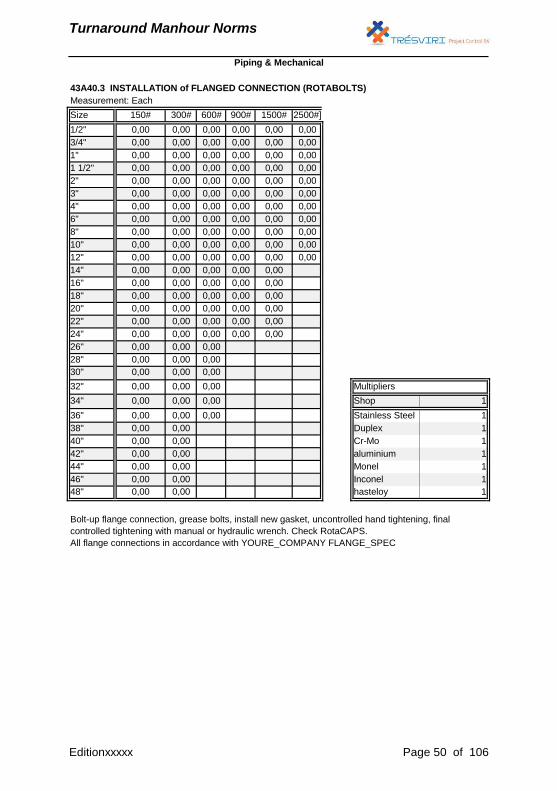
43A40.3 INSTALLATION of FLANGED CONNECTION (ROTABOLTS)
Bolt-up flange connection, grease bolts, install new gasket, uncontrolled hand tightening, final
controlled tightening with manual or hydraulic wrench. Check RotaCAPS.
All flange connections in accordance with YOURE_COMPANY FLANGE_SPEC
Piping & Mechanical
Editionxxxxx Page 50 of 106
Turnaround Manhour Norms
Measurement: Each
Size 150# 300# 600# 900# 1500# 2500#]
1/2" 0,00 0,00 0,00 0,00 0,00 0,00
3/4" 0,00 0,00 0,00 0,00 0,00 0,00
1" 0,00 0,00 0,00 0,00 0,00 0,00
1 1/2" 0,00 0,00 0,00 0,00 0,00 0,00
2" 0,00 0,00 0,00 0,00 0,00 0,00
3" 0,00 0,00 0,00 0,00 0,00 0,00
4" 0,00 0,00 0,00 0,00 0,00 0,00
6" 0,00 0,00 0,00 0,00 0,00 0,00
8" 0,00 0,00 0,00 0,00 0,00 0,00
10" 0,00 0,00 0,00 0,00 0,00 0,00
12" 0,00 0,00 0,00 0,00 0,00 0,00
14" 0,00 0,00 0,00 0,00 0,00
16" 0,00 0,00 0,00 0,00 0,00
18" 0,00 0,00 0,00 0,00 0,00
20" 0,00 0,00 0,00 0,00 0,00
22" 0,00 0,00 0,00 0,00 0,00
24" 0,00 0,00 0,00 0,00 0,00
26" 0,00 0,00 0,00
28" 0,00 0,00 0,00
30" 0,00 0,00 0,00
32" 0,00 0,00 0,00 Multipliers
34" 0,00 0,00 0,00 Shop 1
36" 0,00 0,00 0,00 Stainless Steel 1
38" 0,00 0,00 Duplex 1
40" 0,00 0,00 Cr-Mo 1
42" 0,00 0,00 aluminium 1
44" 0,00 0,00 Monel 1
46" 0,00 0,00 Inconel 1
48" 0,00 0,00 hasteloy 1
Piping & Mechanical
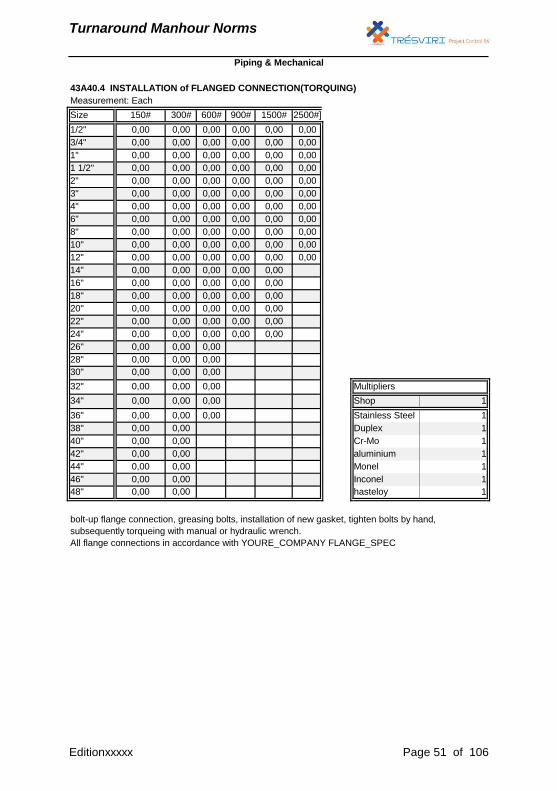
43A40.4 INSTALLATION of FLANGED CONNECTION(TORQUING)
bolt-up flange connection, greasing bolts, installation of new gasket, tighten bolts by hand,
subsequently torqueing with manual or hydraulic wrench.
All flange connections in accordance with YOURE_COMPANY FLANGE_SPEC
Editionxxxxx Page 51 of 106
Turnaround Manhour Norms
Measurement: Each
Size 150# 300# 600# 900# 1500# 2500#]
1/2" 0,00 0,00 0,00 0,00 0,00 0,00
3/4" 0,00 0,00 0,00 0,00 0,00 0,00
1" 0,00 0,00 0,00 0,00 0,00 0,00
1 1/2" 0,00 0,00 0,00 0,00 0,00 0,00
2" 0,00 0,00 0,00 0,00 0,00 0,00
3" 0,00 0,00 0,00 0,00 0,00 0,00
4" 0,00 0,00 0,00 0,00 0,00 0,00
6" 0,00 0,00 0,00 0,00 0,00 0,00
8" 0,00 0,00 0,00 0,00 0,00 0,00
10" 0,00 0,00 0,00 0,00 0,00 0,00
12" 0,00 0,00 0,00 0,00 0,00 0,00
14" 0,00 0,00
16" 0,00 0,00
18" 0,00 0,00
20" 0,00 0,00
22" 0,00 0,00
24" 0,00 0,00
26" 0,00 0,00
28" 0,00 0,00
30" 0,00 0,00
32" 0,00 0,00 Multipliers
34" 0,00 0,00 Shop 1
36" 0,00 0,00 Stainless Steel 1
38" 0,00 0,00 Duplex 1
40" 0,00 0,00 Cr-Mo 1
42" 0,00 0,00 aluminium 1
44" 0,00 0,00 Monel 1
46" 0,00 0,00 Inconel 1
48" 0,00 0,00 hasteloy 1
Piping & Mechanical
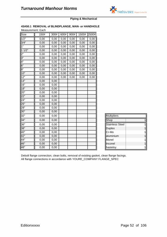
43A50.1 REMOVAL of BLINDFLANGE, MAN- or HANDHOLE
Debolt flange connection, clean bolts, removal of existing gasket, clean flange facings.
All flange connections in accordance with YOURE_COMPANY FLANGE_SPEC
Editionxxxxx Page 52 of 106
Turnaround Manhour Norms
Measurement: Each
Size 150# 300# 600# 900# 1500# 2500#]
1/2" 0,00 0,00 0,00 0,00 0,00 0,00
3/4" 0,00 0,00 0,00 0,00 0,00 0,00
1" 0,00 0,00 0,00 0,00 0,00 0,00
1 1/2" 0,00 0,00 0,00 0,00 0,00 0,00
2" 0,00 0,00 0,00 0,00 0,00 0,00
3" 0,00 0,00 0,00 0,00 0,00 0,00
4" 0,00 0,00 0,00 0,00 0,00 0,00
6" 0,00 0,00 0,00 0,00 0,00 0,00
8" 0,00 0,00 0,00 0,00 0,00 0,00
10" 0,00 0,00 0,00 0,00 0,00 0,00
12" 0,00 0,00 0,00 0,00 0,00 0,00
14" 0,00 0,00
16" 0,00 0,00
18" 0,00 0,00
20" 0,00 0,00
22" 0,00 0,00
24" 0,00 0,00
26" 0,00 0,00
28" 0,00 0,00
30" 0,00 0,00
32" 0,00 0,00 Multipliers
34" 0,00 0,00 Shop 1
36" 0,00 0,00 Stainless Steel 1
38" 0,00 0,00 Duplex 1
40" 0,00 0,00 Cr-Mo 1
42" 0,00 0,00 aluminium 1
44" 0,00 0,00 Monel 1
46" 0,00 0,00 Inconel 1
48" 0,00 0,00 hasteloy 1
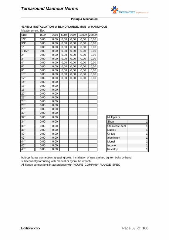
43A50.2 INSTALLATION of BLINDFLANGE, MAN- or HANDHOLE
bolt-up flange connection, greasing bolts, installation of new gasket, tighten bolts by hand,
subsequently torqueing with manual or hydraulic wrench.
All flange connections in accordance with YOURE_COMPANY FLANGE_SPEC
Piping & Mechanical
Editionxxxxx Page 53 of 106
Turnaround Manhour Norms
Measurement: Each
Size 150# 300# 600# 900# 1500# 2500#]
1/2" 0,00 0,00 0,00 0,00 0,00 0,00
3/4" 0,00 0,00 0,00 0,00 0,00 0,00
1" 0,00 0,00 0,00 0,00 0,00 0,00
1 1/2" 0,00 0,00 0,00 0,00 0,00 0,00
2" 0,00 0,00 0,00 0,00 0,00 0,00
3" 0,00 0,00 0,00 0,00 0,00 0,00
4" 0,00 0,00 0,00 0,00 0,00 0,00
6" 0,00 0,00 0,00 0,00 0,00 0,00
8" 0,00 0,00 0,00 0,00 0,00 0,00
10" 0,00 0,00 0,00 0,00 0,00 0,00
12" 0,00 0,00 0,00 0,00 0,00 0,00
14" 0,00 0,00 0,00 0,00 0,00
16" 0,00 0,00 0,00 0,00 0,00
18" 0,00 0,00 0,00 0,00 0,00
20" 0,00 0,00 0,00 0,00 0,00
22" 0,00 0,00 0,00 0,00 0,00
24" 0,00 0,00 0,00 0,00 0,00
26" 0,00 0,00 0,00
28" 0,00 0,00 0,00
30" 0,00 0,00 0,00
32" 0,00 0,00 0,00 Multipliers
34" 0,00 0,00 0,00 Shop 1
36" 0,00 0,00 0,00 Stainless Steel 1
38" 0,00 0,00 Duplex 1
40" 0,00 0,00 Cr-Mo 1
42" 0,00 0,00 aluminium 1
44" 0,00 0,00 Monel 1
46" 0,00 0,00 Inconel 1
48" 0,00 0,00 hasteloy 1
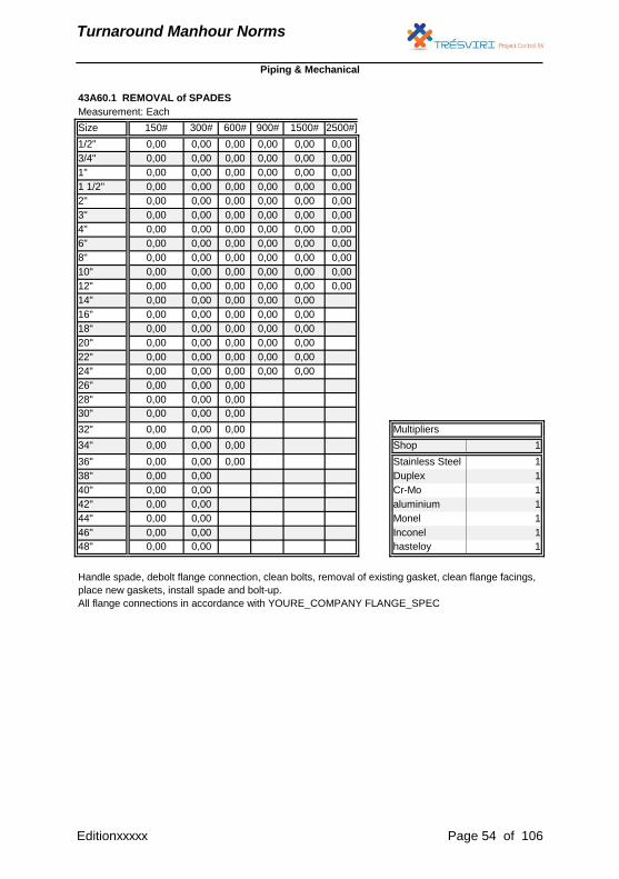
Handle spade, debolt flange connection, clean bolts, removal of existing gasket, clean flange facings,
place new gaskets, install spade and bolt-up.
All flange connections in accordance with YOURE_COMPANY FLANGE_SPEC
43A60.1 REMOVAL of SPADES
Piping & Mechanical
Editionxxxxx Page 54 of 106

Turnaround Manhour Norms
Measurement: Each
Size 150# 300# 600# 900# 1500# 2500#]
1/2" 0,00 0,00 0,00 0,00 0,00 0,00
3/4" 0,00 0,00 0,00 0,00 0,00 0,00
1" 0,00 0,00 0,00 0,00 0,00 0,00
1 1/2" 0,00 0,00 0,00 0,00 0,00 0,00
2" 0,00 0,00 0,00 0,00 0,00 0,00
3" 0,00 0,00 0,00 0,00 0,00 0,00
4" 0,00 0,00 0,00 0,00 0,00 0,00
6" 0,00 0,00 0,00 0,00 0,00 0,00
8" 0,00 0,00 0,00 0,00 0,00 0,00
10" 0,00 0,00 0,00 0,00 0,00 0,00
12" 0,00 0,00 0,00 0,00 0,00 0,00
14" 0,00 0,00 0,00 0,00 0,00
16" 0,00 0,00 0,00 0,00 0,00
18" 0,00 0,00 0,00 0,00 0,00
20" 0,00 0,00 0,00 0,00 0,00
22" 0,00 0,00 0,00 0,00 0,00
24" 0,00 0,00 0,00 0,00 0,00
26" 0,00 0,00 0,00
28" 0,00 0,00 0,00
30" 0,00 0,00 0,00
32" 0,00 0,00 0,00 Multipliers
34" 0,00 0,00 0,00 Shop 1
36" 0,00 0,00 0,00 Stainless Steel 1
38" 0,00 0,00 Duplex 1
40" 0,00 0,00 Cr-Mo 1
42" 0,00 0,00 aluminium 1
44" 0,00 0,00 Monel 1
46" 0,00 0,00 Inconel 1
48" 0,00 0,00 hasteloy 1
Handle spade, debolt flange connection, clean bolts, removal of existing gasket, clean flange facings,
place new gaskets, install spade and bolt-up.
All flange connections in accordance with YOURE_COMPANY FLANGE_SPEC
43A60.2 INSTALLATION of SPADES
Piping & Mechanical
Editionxxxxx Page 55 of 106

Turnaround Manhour Norms
Measurement: Each
Size 150# 300# 600# 900# 1500# 2500#]
1/2" 0,00 0,00 0,00 0,00 0,00 0,00
3/4" 0,00 0,00 0,00 0,00 0,00 0,00
1" 0,00 0,00 0,00 0,00 0,00 0,00
1 1/4" 0,00 0,00 0,00 0,00 0,00 0,00
1 1/2" 0,00 0,00 0,00 0,00 0,00 0,00
2" 0,00 0,00 0,00 0,00 0,00 0,00
2 1/2" 0,00 0,00 0,00 0,00 0,00 0,00
3" 0,00 0,00 0,00 0,00 0,00 0,00
4" 0,00 0,00 0,00 0,00 0,00 0,00
6" 0,00 0,00 0,00 0,00 0,00 0,00
8" 0,00 0,00 0,00 0,00 0,00 0,00
10" 0,00 0,00 0,00 0,00 0,00 0,00
12" 0,00 0,00 0,00 0,00 0,00 0,00
14" 0,00 0,00 0,00 0,00 0,00 0,00
16" 0,00 0,00 0,00 0,00 0,00 0,00
18" 0,00 0,00 0,00 0,00 0,00 0,00
20" 0,00 0,00 0,00 0,00 0,00 0,00
22" 0,00 0,00 0,00 0,00 0,00 0,00
24" 0,00 0,00 0,00 0,00 0,00 0,00
26" 0,00 0,00 0,00 0,00 0,00 0,00
28" 0,00 0,00 0,00 0,00 0,00 0,00
30" 0,00 0,00 0,00 0,00 0,00 0,00
32" 0,00 0,00 0,00 0,00 0,00 0,00 Multipliers
34" 0,00 0,00 0,00 0,00 0,00 0,00 Shop 1
36" 0,00 0,00 0,00 0,00 0,00 0,00 Stainless Steel 1
38" 0,00 0,00 0,00 0,00 0,00 0,00 Duplex 1
40" 0,00 0,00 0,00 0,00 0,00 0,00 Cr-Mo 1
42" 0,00 0,00 0,00 0,00 0,00 0,00 aluminium 1
44" 0,00 0,00 0,00 0,00 0,00 0,00 Monel 1
46" 0,00 0 0 0 0 0 Inconel 1
48" 0,00 0,00 0,00 0,00 0,00 0,00 hasteloy 1
Debolt 2 flange connection, clean bolts, removal of existing gasket, clean flange facings.
All flange connections in accordance with YOURE_COMPANY FLANGE_SPEC
Piping & Mechanical
43A70.1 REMOVAL of Manual operated VALVE
Editionxxxxx Page 56 of 106
Turnaround Manhour Norms
Measurement: Each
Size 150# 300# 600# 900# 1500# 2500#]
1/2" 0,00 0,00 0,00 0,00 0,00 0,00
3/4" 0,00 0,00 0,00 0,00 0,00 0,00
1" 0,00 0,00 0,00 0,00 0,00 0,00
1 1/4" 0,00 0,00 0,00 0,00 0,00 0,00
1 1/2" 0,00 0,00 0,00 0,00 0,00 0,00
2" 0,00 0,00 0,00 0,00 0,00 0,00
2 1/2" 0,00 0,00 0,00 0,00 0,00 0,00
3" 0,00 0,00 0,00 0,00 0,00 0,00
4" 0,00 0,00 0,00 0,00 0,00 0,00
6" 0,00 0,00 0,00 0,00 0,00 0,00
8" 0,00 0,00 0,00 0,00 0,00 0,00
10" 0,00 0,00 0,00 0,00 0,00 0,00
12" 0,00 0,00 0,00 0,00 0,00 0,00
14" 0,00 0,00 0,00 0,00 0,00 0,00
16" 0,00 0,00 0,00 0,00 0,00 0,00
18" 0,00 0,00 0,00 0,00 0,00 0,00
20" 0,00 0,00 0,00 0,00 0,00 0,00
22" 0,00 0,00 0,00 0,00 0,00 0,00
24" 0,00 0,00 0,00 0,00 0,00 0,00
26" 0,00 0,00 0,00 0,00 0,00 0,00
28" 0,00 0,00 0,00 0,00 0,00 0,00
30" 0,00 0,00 0,00 0,00 0,00 0,00
32" 0,00 0,00 0,00 0,00 0,00 0,00 Multipliers
34" 0,00 0,00 0,00 0,00 0,00 0,00 Shop 1
36" 0,00 0,00 0,00 0,00 0,00 0,00 Stainless Steel 1
38" 0,00 0,00 0,00 0,00 0,00 0,00 Duplex 1
40" 0,00 0,00 0,00 0,00 0,00 0,00 Cr-Mo 1
42" 0,00 0,00 0,00 0,00 0,00 0,00 aluminium 1
44" 0,00 0,00 0,00 0,00 0,00 0,00 Monel 1
46" 0,00 0 0 0 0 0 Inconel 1
48" 0,00 0,00 0,00 0,00 0,00 0,00 hasteloy 1
Piping & Mechanical
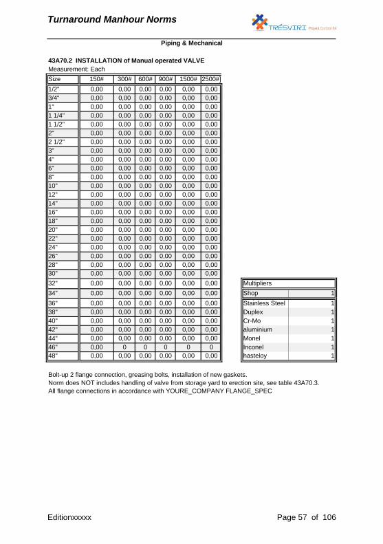
Bolt-up 2 flange connection, greasing bolts, installation of new gaskets.
Norm does NOT includes handling of valve from storage yard to erection site, see table 43A70.3.
All flange connections in accordance with YOURE_COMPANY FLANGE_SPEC
43A70.2 INSTALLATION of Manual operated VALVE
Editionxxxxx Page 57 of 106
Turnaround Manhour Norms
Measurement: Each
Size 150# 300# 600# 900# 1500# 2500#]
1/2" 0,00 0,00 0,00 0,00 0,00 0,00
3/4" 0,00 0,00 0,00 0,00 0,00 0,00
1" 0,00 0,00 0,00 0,00 0,00 0,00
1 1/2" 0,00 0,00 0,00 0,00 0,00 0,00
2" 0,00 0,00 0,00 0,00 0,00 0,00
3" 0,00 0,00 0,00 0,00 0,00 0,00
4" 0,00 0,00 0,00 0,00 0,00 0,00
6" 0,00 0,00 0,00 0,00 0,00 0,00
8" 0,00 0,00 0,00 0,00 0,00 0,00
10" 0,00 0,00 0,00 0,00 0,00 0,00
12" 0,00 0,00 0,00 0,00 0,00 0,00
14" 0,00 0,00 0,00 0,00 0,00
16" 0,00 0,00 0,00 0,00 0,00
18" 0,00 0,00 0,00 0,00 0,00
20" 0,00 0,00 0,00 0,00 0,00
22" 0,00 0,00 0,00 0,00 0,00
24" 0,00 0,00 0,00 0,00 0,00
26" 0,00 0,00 0,00
28" 0,00 0,00 0,00
30" 0,00 0,00 0,00
32" 0,00 0,00 0,00 Multipliers
34" 0,00 0,00 0,00 Shop 1
36" 0,00 0,00 0,00 Stainless Steel 1
38" 0,00 0,00 0,00 Duplex 1
40" 0,00 0,00 0,00 Cr-Mo 1
42" 0,00 0,00 0,00 aluminium 1
44" 0,00 0,00 0,00 Monel 1
46" 0,00 0,00 0,00 Inconel 1
48" 0,00 0,00 0,00 hasteloy 1
Piping & Mechanical
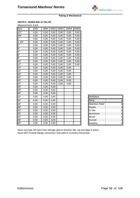
43A70.3 HANDLING of VALVE
Move any type off valve from storage yard to erection site, rig and align in place.
Does NOT include flange connection, butt weld or screwed connection.
Editionxxxxx Page 58 of 106
Turnaround Manhour Norms
Measurement: Each
Size 150# 300# 600# 900# 1500# 2500#]
1/2" 0,00 0,00 0,00 0,00 0,00 0,00
3/4" 0,00 0,00 0,00 0,00 0,00 0,00
1" 0,00 0,00 0,00 0,00 0,00 0,00
1 1/2" 0,00 0,00 0,00 0,00 0,00 0,00
2" 0,00 0,00 0,00 0,00 0,00 0,00
3" 0,00 0,00 0,00 0,00 0,00 0,00
4" 0,00 0,00 0,00 0,00 0,00 0,00
6" 0,00 0,00 0,00 0,00 0,00 0,00
8" 0,00 0,00 0,00 0,00 0,00 0,00
10" 0,00 0,00 0,00 0,00 0,00 0,00
12" 0,00 0,00 0,00 0,00 0,00 0,00
14" 0,00 0,00 0,00 0,00 0,00
16" 0,00 0,00 0,00 0,00 0,00
18" 0,00 0,00 0,00 0,00 0,00
20" 0,00 0,00 0,00 0,00 0,00
22" 0,00 0,00 0,00 0,00 0,00
24" 0,00 0,00 0,00 0,00 0,00
26" 0,00 0,00 0,00
28" 0,00 0,00 0,00
30" 0,00 0,00 0,00
32" 0,00 0,00 0,00 Multipliers
34" 0,00 0,00 0,00 Shop 1
36" 0,00 0,00 0,00 Stainless Steel 1
38" 0,00 0,00 Duplex 1
40" 0,00 0,00 Cr-Mo 1
42" 0,00 0,00 aluminium 1
44" 0,00 0,00 Monel 1
46" 0,00 0,00 Inconel 1
48" 0,00 0,00 hasteloy 1
Piping & Mechanical
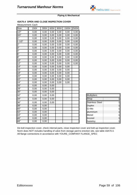
43A70.4 OPEN AND CLOSE INSPECTION COVER
De-bolt inspection cover, check internal parts, close inspection cover and bolt-up inspection cover.
Norm does NOT includes handling of valve from storage yard to erection site, see table 43A70.3.
All flange connections in accordance with YOURE_COMPANY FLANGE_SPEC
Editionxxxxx Page 59 of 106
Turnaround Manhour Norms
Measurement: Each
Size 150# 300# 600# 900# 1500# 2500#]
1/2" 0,00 0,00 0,00 0,00 0,00 0,00
3/4" 0,00 0,00 0,00 0,00 0,00 0,00
1" 0,00 0,00 0,00 0,00 0,00 0,00
1 1/4" 0,00 0,00 0,00 0,00 0,00 0,00
1 1/2" 0,00 0,00 0,00 0,00 0,00 0,00
2" 0,00 0,00 0,00 0,00 0,00 0,00
2 1/2" 0,00 0,00 0,00 0,00 0,00 0,00
3" 0,00 0,00 0,00 0,00 0,00 0,00
4" 0,00 0,00 0,00 0,00 0,00 0,00
6" 0,00 0,00 0,00 0,00 0,00 0,00
8" 0,00 0,00 0,00 0,00 0,00 0,00
10" 0,00 0,00 0,00 0,00 0,00 0,00
12" 0,00 0,00 0,00 0,00 0,00 0,00
14" 0,00 0,00 0,00 0,00 0,00 0,00
16" 0,00 0,00 0,00 0,00 0,00 0,00
18" 0,00 0,00 0,00 0,00 0,00 0,00
20" 0,00 0,00 0,00 0,00 0,00 0,00
22" 0,00 0,00 0,00 0,00 0,00 0,00
24" 0,00 0,00 0,00 0,00 0,00 0,00
26" 0,00 0,00 0,00 0,00 0,00 0,00
28" 0,00 0,00 0,00 0,00 0,00 0,00
30" 0,00 0,00 0,00 0,00 0,00 0,00
32" 0,00 0,00 0,00 0,00 0,00 0,00 Multipliers
34" 0,00 0,00 0,00 0,00 0,00 0,00 Shop 1
36" 0,00 0,00 0,00 0,00 0,00 0,00 Stainless Steel 1
38" 0,00 0,00 0,00 0,00 0,00 0,00 Duplex 1
40" 0,00 0,00 0,00 0,00 0,00 0,00 Cr-Mo 1
42" 0,00 0,00 0,00 0,00 0,00 0,00 aluminium 1
44" 0,00 0,00 0,00 0,00 0,00 0,00 Monel 1
46" 0,00 0,00 0,00 0,00 0,00 0,00 Inconel 1
48" 0,00 0,00 0,00 0,00 0,00 0,00 hasteloy 1
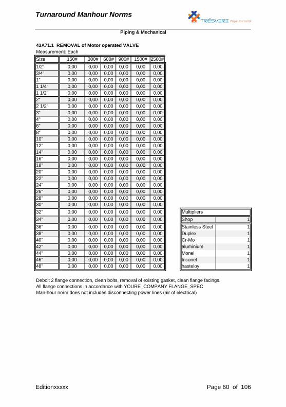
43A71.1 REMOVAL of Motor operated VALVE
Debolt 2 flange connection, clean bolts, removal of existing gasket, clean flange facings.
All flange connections in accordance with YOURE_COMPANY FLANGE_SPEC
Man-hour norm does not includes disconnecting power lines (air of electrical)
Piping & Mechanical
Editionxxxxx Page 60 of 106
Turnaround Manhour Norms
Measurement: Each
Size 150# 300# 600# 900# 1500# 2500#]
1/2" 0,00 0,00 0,00 0,00 0,00 0,00
3/4" 0,00 0,00 0,00 0,00 0,00 0,00
1" 0,00 0,00 0,00 0,00 0,00 0,00
1 1/4" 0,00 0,00 0,00 0,00 0,00 0,00
1 1/2" 0,00 0,00 0,00 0,00 0,00 0,00
2" 0,00 0,00 0,00 0,00 0,00 0,00
2 1/2" 0,00 0,00 0,00 0,00 0,00 0,00
3" 0,00 0,00 0,00 0,00 0,00 0,00
4" 0,00 0,00 0,00 0,00 0,00 0,00
6" 0,00 0,00 0,00 0,00 0,00 0,00
8" 0,00 0,00 0,00 0,00 0,00 0,00
10" 0,00 0,00 0,00 0,00 0,00 0,00
12" 0,00 0,00 0,00 0,00 0,00 0,00
14" 0,00 0,00 0,00 0,00 0,00 0,00
16" 0,00 0,00 0,00 0,00 0,00 0,00
18" 0,00 0,00 0,00 0,00 0,00 0,00
20" 0,00 0,00 0,00 0,00 0,00 0,00
22" 0,00 0,00 0,00 0,00 0,00 0,00
24" 0,00 0,00 0,00 0,00 0,00 0,00
26" 0,00 0,00 0,00 0,00 0,00 0,00
28" 0,00 0,00 0,00 0,00 0,00 0,00
30" 0,00 0,00 0,00 0,00 0,00 0,00
32" 0,00 0,00 0,00 0,00 0,00 0,00 Multipliers
34" 0,00 0,00 0,00 0,00 0,00 0,00 Shop 1
36" 0,00 0,00 0,00 0,00 0,00 0,00 Stainless Steel 1
38" 0,00 0,00 0,00 0,00 0,00 0,00 Duplex 1
40" 0,00 0,00 0,00 0,00 0,00 0,00 Cr-Mo 1
42" 0,00 0,00 0,00 0,00 0,00 0,00 aluminium 1
44" 0,00 0,00 0,00 0,00 0,00 0,00 Monel 1
46" 0,00 0,00 0,00 0,00 0,00 0,00 Inconel 1
48" 0,00 0,00 0,00 0,00 0,00 0,00 hasteloy 1
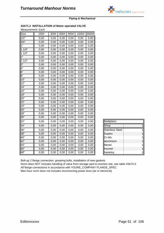
43A71.2 INSTALLATION of Motor operated VALVE
Bolt-up 2 flange connection, greasing bolts, installation of new gaskets.
Norm does NOT includes handling of valve from storage yard to erection site, see table 43A70.3.
All flange connections in accordance with YOURE_COMPANY FLANGE_SPEC
Man-hour norm does not includes reconnecting power lines (air or electrical)
Piping & Mechanical
Editionxxxxx Page 61 of 106
Turnaround Manhour Norms
Measurement: Each
Size 150# 300# 600# 900# 1500# 2500#]
1/2" 0,00 0,00 0,00 0,00 0,00 0,00 Multipliers
3/4" 0,00 0,00 0,00 0,00 0,00 0,00 Shop 1
1" 0,00 0,00 0,00 0,00 0,00 0,00 Stainless Steel 1
1 1/4" 0,00 0,00 0,00 0,00 0,00 0,00 Duplex 1
1 1/2" 0,00 0,00 0,00 0,00 0,00 0,00 Cr-Mo 1
2" 0,00 0,00 0,00 0,00 0,00 0,00 aluminium 1
2 1/2" 0,00 0,00 0,00 0,00 0,00 0,00 Monel 1
3" 0,00 0,00 0,00 0,00 0,00 0,00 Inconel 1
4" 0,00 0,00 0,00 0,00 0,00 0,00 hasteloy 1
6" 0,00 0,00 0,00 0,00 0,00 0,00
8" 0,00 0,00 0,00 0,00 0,00 0,00
10" 0,00 0,00 0,00 0,00 0,00 0,00
12" 0,00 0,00 0,00 0,00 0,00 0,00
14" 0,00 0,00 0,00
16" 0,00 0,00 0,00
18" 0,00 0,00 0,00
20" 0,00 0,00 0,00
Piping & Mechanical
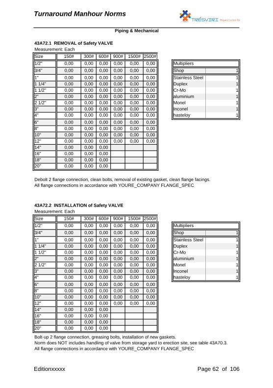
43A72.1 REMOVAL of Safety VALVE
Debolt 2 flange connection, clean bolts, removal of existing gasket, clean flange facings.
All flange connections in accordance with YOURE_COMPANY FLANGE_SPEC
43A72.2 INSTALLATION of Safety VALVE
Bolt-up 2 flange connection, greasing bolts, installation of new gaskets.
Norm does NOT includes handling of valve from storage yard to erection site, see table 43A70.3.
All flange connections in accordance with YOURE_COMPANY FLANGE_SPEC
Editionxxxxx Page 62 of 106
Turnaround Manhour Norms
Measurement: Each
Size 150# 300# 600# 900# 1500# 2500#]
1/2" 0,00 0,00 0,00 Multipliers
3/4" 0,00 0,00 0,00 Shop 1
1" 0,00 0,00 0,00 Stainless Steel 1
1 1/4" 0,00 0,00 0,00 Duplex 1
1 1/2" 0,00 0,00 0,00 Cr-Mo 1
2" 0,00 0,00 0,00 aluminium 1
2 1/2" 0,00 0,00 0,00 Monel 1
3" 0,00 0,00 0,00 Inconel 1
4" 0,00 0,00 0,00 hasteloy 1
6" 0,00 0,00 0,00
8" 0,00 0,00 0,00
10" 0,00 0,00 0,00
12" 0,00 0,00 0,00
14" 0,00 0,00 0,00
16" 0,00 0,00 0,00
18" 0,00 0,00 0,00
20" 0,00 0,00 0,00
22" 0,00 0,00 0,00
24" 0,00 0,00 0,00
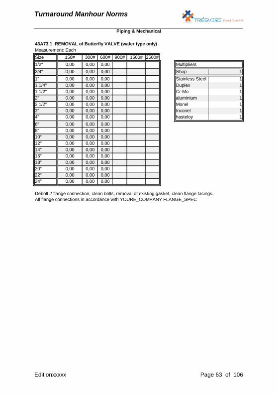
43A73.1 REMOVAL of Butterfly VALVE (wafer type only)
Debolt 2 flange connection, clean bolts, removal of existing gasket, clean flange facings.
All flange connections in accordance with YOURE_COMPANY FLANGE_SPEC
Piping & Mechanical
Editionxxxxx Page 63 of 106

Turnaround Manhour Norms
Measurement: Each
Size 150# 300# 600# 900# 1500# 2500#]
1/2" 0,00 0,00 0,00 Multipliers
3/4" 0,00 0,00 0,00 Shop 1
1" 0,00 0,00 0,00 Stainless Steel 1
1 1/4" 0,00 0,00 0,00 Duplex 1
1 1/2" 0,00 0,00 0,00 Cr-Mo 1
2" 0,00 0,00 0,00 aluminium 1
2 1/2" 0,00 0,00 0,00 Monel 1
3" 0,00 0,00 0,00 Inconel 1
4" 0,00 0,00 0,00 hasteloy 1
6" 0,00 0,00 0,00
8" 0,00 0,00 0,00
10" 0,00 0,00 0,00
12" 0,00 0,00 0,00
14" 0,00 0,00 0,00
16" 0,00 0,00 0,00
18" 0,00 0,00 0,00
20" 0,00 0,00 0,00
22" 0,00 0,00 0,00
24" 0,00 0,00 0,00
Piping & Mechanical
43A73.2 INSTALLATION of Butterfly VALVE (wafer type only)
Bolt-up 2 flange connection, greasing bolts, installation of new gaskets.
Norm does NOT includes handling of valve from storage yard to erection site, see table 43A70.3.
All flange connections in accordance with YOURE_COMPANY FLANGE_SPEC
Editionxxxxx Page 64 of 106
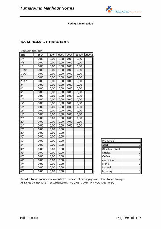
Turnaround Manhour Norms
Measurement: Each
Size 150# 300# 600# 900# 1500# 2500#]
1/2" 0,00 0,00 0,00 0,00 0,00
3/4" 0,00 0,00 0,00 0,00 0,00
1" 0,00 0,00 0,00 0,00 0,00
1 1/4" 0,00 0,00 0,00 0,00 0,00
1 1/2" 0,00 0,00 0,00 0,00 0,00
2" 0,00 0,00 0,00 0,00 0,00
2 1/2" 0,00 0,00 0,00 0,00 0,00
3" 0,00 0,00 0,00 0,00 0,00
4" 0,00 0,00 0,00 0,00 0,00
6" 0,00 0,00 0,00 0,00 0,00
8" 0,00 0,00 0,00 0,00 0,00
10" 0,00 0,00 0,00 0,00 0,00
12" 0,00 0,00 0,00 0,00 0,00
14" 0,00 0,00 0,00 0,00 0,00
16" 0,00 0,00 0,00 0,00 0,00
18" 0,00 0,00 0,00 0,00 0,00
20" 0,00 0,00 0,00 0,00 0,00
22" 0,00 0,00 0,00 0,00 0,00
24" 0,00 0,00 0,00 0,00 0,00
26" 0,00 0,00 0,00
28" 0,00 0,00 0,00
30" 0,00 0,00 0,00
32" 0,00 0,00 0,00 Multipliers
34" 0,00 0,00 0,00 Shop 1
36" 0,00 0,00 0,00 Stainless Steel 1
38" 0,00 0,00 0,00 Duplex 1
40" 0,00 0,00 0,00 Cr-Mo 1
42" 0,00 0,00 0,00 aluminium 1
44" 0,00 0,00 0,00 Monel 1
46" 0,00 0,00 0,00 Inconel 1
48" 0,00 0,00 0,00 hasteloy 1
Piping & Mechanical
43A74.1 REMOVAL of Filters/strainers
Debolt 2 flange connection, clean bolts, removal of existing gasket, clean flange facings.
All flange connections in accordance with YOURE_COMPANY FLANGE_SPEC
Editionxxxxx Page 65 of 106
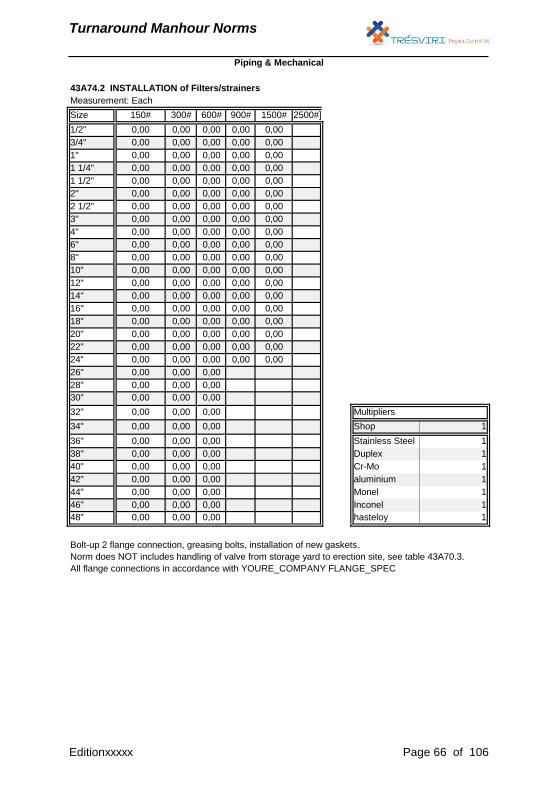
Turnaround Manhour Norms
Measurement: Each
Size 150# 300# 600# 900# 1500# 2500#]
1/2" 0,00 0,00 0,00 0,00 0,00
3/4" 0,00 0,00 0,00 0,00 0,00
1" 0,00 0,00 0,00 0,00 0,00
1 1/4" 0,00 0,00 0,00 0,00 0,00
1 1/2" 0,00 0,00 0,00 0,00 0,00
2" 0,00 0,00 0,00 0,00 0,00
2 1/2" 0,00 0,00 0,00 0,00 0,00
3" 0,00 0,00 0,00 0,00 0,00
4" 0,00 0,00 0,00 0,00 0,00
6" 0,00 0,00 0,00 0,00 0,00
8" 0,00 0,00 0,00 0,00 0,00
10" 0,00 0,00 0,00 0,00 0,00
12" 0,00 0,00 0,00 0,00 0,00
14" 0,00 0,00 0,00 0,00 0,00
16" 0,00 0,00 0,00 0,00 0,00
18" 0,00 0,00 0,00 0,00 0,00
20" 0,00 0,00 0,00 0,00 0,00
22" 0,00 0,00 0,00 0,00 0,00
24" 0,00 0,00 0,00 0,00 0,00
26" 0,00 0,00 0,00
28" 0,00 0,00 0,00
30" 0,00 0,00 0,00
32" 0,00 0,00 0,00 Multipliers
34" 0,00 0,00 0,00 Shop 1
36" 0,00 0,00 0,00 Stainless Steel 1
38" 0,00 0,00 0,00 Duplex 1
40" 0,00 0,00 0,00 Cr-Mo 1
42" 0,00 0,00 0,00 aluminium 1
44" 0,00 0,00 0,00 Monel 1
46" 0,00 0,00 0,00 Inconel 1
48" 0,00 0,00 0,00 hasteloy 1
Piping & Mechanical
43A74.2 INSTALLATION of Filters/strainers
Bolt-up 2 flange connection, greasing bolts, installation of new gaskets.
Norm does NOT includes handling of valve from storage yard to erection site, see table 43A70.3.
All flange connections in accordance with YOURE_COMPANY FLANGE_SPEC
Editionxxxxx Page 66 of 106
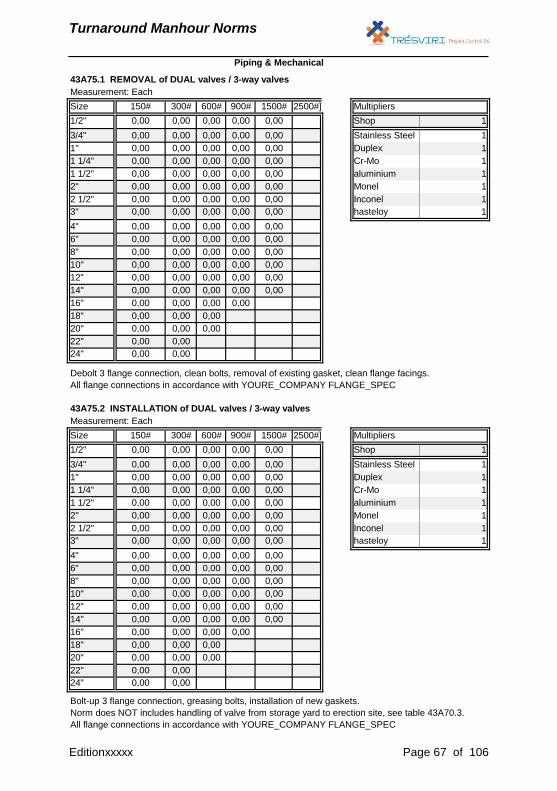
Turnaround Manhour Norms
Measurement: Each
Size 150# 300# 600# 900# 1500# 2500#] Multipliers
1/2" 0,00 0,00 0,00 0,00 0,00 Shop 1
3/4" 0,00 0,00 0,00 0,00 0,00 Stainless Steel 1
1" 0,00 0,00 0,00 0,00 0,00 Duplex 1
1 1/4" 0,00 0,00 0,00 0,00 0,00 Cr-Mo 1
1 1/2" 0,00 0,00 0,00 0,00 0,00 aluminium 1
2" 0,00 0,00 0,00 0,00 0,00 Monel 1
2 1/2" 0,00 0,00 0,00 0,00 0,00 Inconel 1
3" 0,00 0,00 0,00 0,00 0,00 hasteloy 1
4" 0,00 0,00 0,00 0,00 0,00
6" 0,00 0,00 0,00 0,00 0,00
8" 0,00 0,00 0,00 0,00 0,00
10" 0,00 0,00 0,00 0,00 0,00
12" 0,00 0,00 0,00 0,00 0,00
14" 0,00 0,00 0,00 0,00 0,00
16" 0,00 0,00 0,00 0,00
18" 0,00 0,00 0,00
20" 0,00 0,00 0,00
22" 0,00 0,00
24" 0,00 0,00
Piping & Mechanical
43A75.1 REMOVAL of DUAL valves / 3-way valves
Debolt 3 flange connection, clean bolts, removal of existing gasket, clean flange facings.
All flange connections in accordance with YOURE_COMPANY FLANGE_SPEC
43A75.2 INSTALLATION of DUAL valves / 3-way valves
Bolt-up 3 flange connection, greasing bolts, installation of new gaskets.
Norm does NOT includes handling of valve from storage yard to erection site, see table 43A70.3.
All flange connections in accordance with YOURE_COMPANY FLANGE_SPEC
Editionxxxxx Page 67 of 106
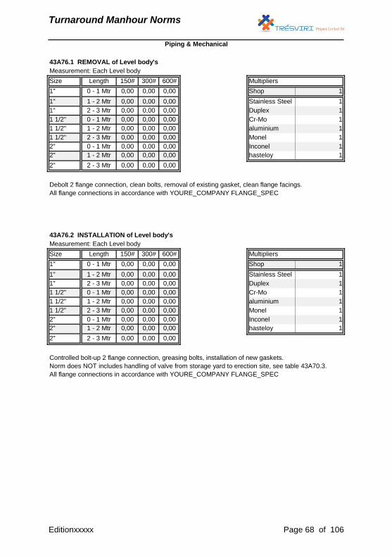
Turnaround Manhour Norms
Measurement: Each Level body
Size Length 150# 300# 600# Multipliers
1" 0 - 1 Mtr 0,00 0,00 0,00 Shop 1
1" 1 - 2 Mtr 0,00 0,00 0,00 Stainless Steel 1
1" 2 - 3 Mtr 0,00 0,00 0,00 Duplex 1
1 1/2" 0 - 1 Mtr 0,00 0,00 0,00 Cr-Mo 1
1 1/2" 1 - 2 Mtr 0,00 0,00 0,00 aluminium 1
1 1/2" 2 - 3 Mtr 0,00 0,00 0,00 Monel 1
2" 0 - 1 Mtr 0,00 0,00 0,00 Inconel 1
2" 1 - 2 Mtr 0,00 0,00 0,00 hasteloy 1
2" 2 - 3 Mtr 0,00 0,00 0,00
Piping & Mechanical
43A76.1 REMOVAL of Level body's
Debolt 2 flange connection, clean bolts, removal of existing gasket, clean flange facings.
All flange connections in accordance with YOURE_COMPANY FLANGE_SPEC
43A76.2 INSTALLATION of Level body's
Controlled bolt-up 2 flange connection, greasing bolts, installation of new gaskets.
Norm does NOT includes handling of valve from storage yard to erection site, see table 43A70.3.
All flange connections in accordance with YOURE_COMPANY FLANGE_SPEC
Editionxxxxx Page 68 of 106
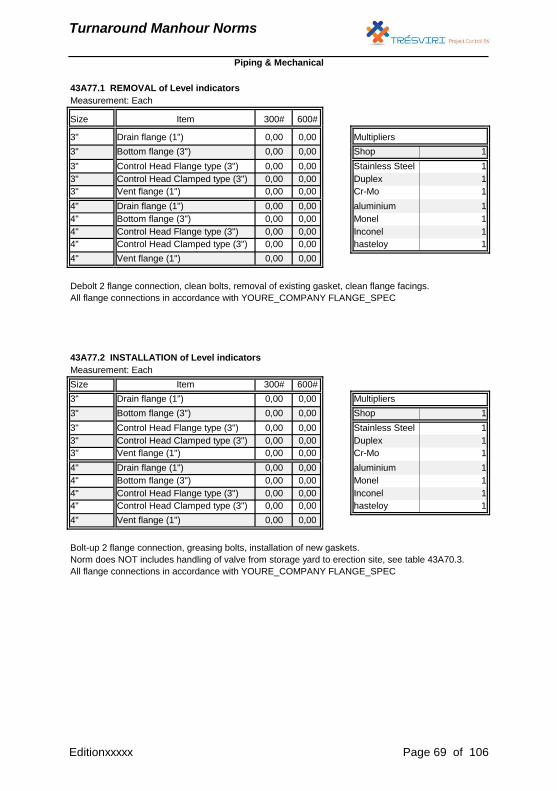
Turnaround Manhour Norms
Measurement: Each
Size 300# 600#
3" 0,00 0,00 Multipliers
3" 0,00 0,00 Shop 1
3" 0,00 0,00 Stainless Steel 1
3" 0,00 0,00 Duplex 1
3" 0,00 0,00 Cr-Mo 1
4" 0,00 0,00 aluminium 1
4" 0,00 0,00 Monel 1
4" 0,00 0,00 Inconel 1
4" 0,00 0,00 hasteloy 1
4" 0,00 0,00
Measurement: Each
Size 300# 600#
3" 0,00 0,00 Multipliers
3" 0,00 0,00 Shop 1
3" 0,00 0,00 Stainless Steel 1
3" 0,00 0,00 Duplex 1
3" 0,00 0,00 Cr-Mo 1
4" 0,00 0,00 aluminium 1
4" 0,00 0,00 Monel 1
4" 0,00 0,00 Inconel 1
4" 0,00 0,00 hasteloy 1
4" 0,00 0,00
43A77.1 REMOVAL of Level indicators
Debolt 2 flange connection, clean bolts, removal of existing gasket, clean flange facings.
All flange connections in accordance with YOURE_COMPANY FLANGE_SPEC
43A77.2 INSTALLATION of Level indicators
Bolt-up 2 flange connection, greasing bolts, installation of new gaskets.
Norm does NOT includes handling of valve from storage yard to erection site, see table 43A70.3.
All flange connections in accordance with YOURE_COMPANY FLANGE_SPEC
Drain flange (1")
Bottom flange (3")
Control Head Flange type (3")
Control Head Clamped type (3")
Vent flange (1")
Item
Item
Drain flange (1")
Bottom flange (3")
Control Head Flange type (3")
Control Head Clamped type (3")
Vent flange (1")
Drain flange (1")
Bottom flange (3")
Control Head Flange type (3")
Control Head Clamped type (3")
Vent flange (1")
Drain flange (1")
Bottom flange (3")
Control Head Flange type (3")
Control Head Clamped type (3")
Vent flange (1")
Piping & Mechanical
Editionxxxxx Page 69 of 106
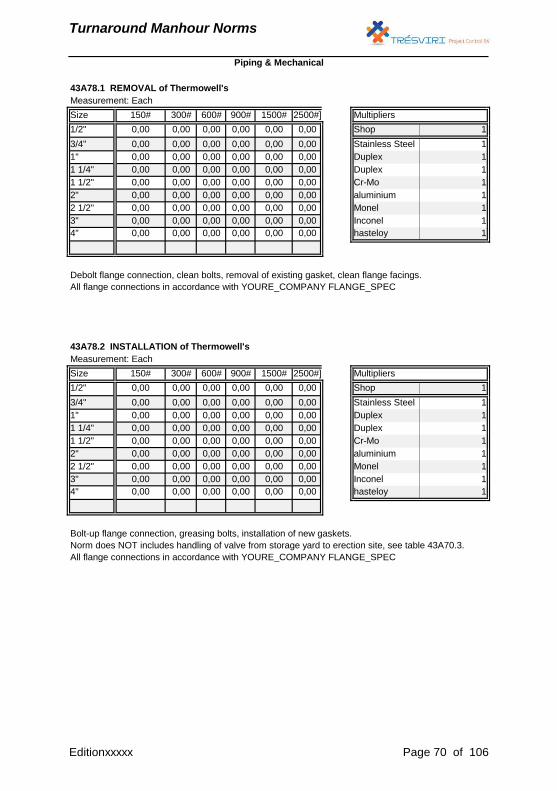
Turnaround Manhour Norms
Measurement: Each
Size 150# 300# 600# 900# 1500# 2500#] Multipliers
1/2" 0,00 0,00 0,00 0,00 0,00 0,00 Shop 1
3/4" 0,00 0,00 0,00 0,00 0,00 0,00 Stainless Steel 1
1" 0,00 0,00 0,00 0,00 0,00 0,00 Duplex 1
1 1/4" 0,00 0,00 0,00 0,00 0,00 0,00 Duplex 1
1 1/2" 0,00 0,00 0,00 0,00 0,00 0,00 Cr-Mo 1
2" 0,00 0,00 0,00 0,00 0,00 0,00 aluminium 1
2 1/2" 0,00 0,00 0,00 0,00 0,00 0,00 Monel 1
3" 0,00 0,00 0,00 0,00 0,00 0,00 Inconel 1
4" 0,00 0,00 0,00 0,00 0,00 0,00 hasteloy 1
43A78.2 INSTALLATION of Thermowell's
Bolt-up flange connection, greasing bolts, installation of new gaskets.
Norm does NOT includes handling of valve from storage yard to erection site, see table 43A70.3.
All flange connections in accordance with YOURE_COMPANY FLANGE_SPEC
Piping & Mechanical
43A78.1 REMOVAL of Thermowell's
Debolt flange connection, clean bolts, removal of existing gasket, clean flange facings.
All flange connections in accordance with YOURE_COMPANY FLANGE_SPEC
Editionxxxxx Page 70 of 106
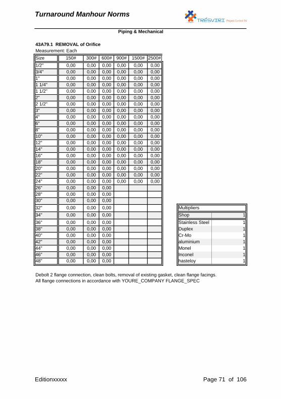
Turnaround Manhour Norms
Measurement: Each
Size 150# 300# 600# 900# 1500# 2500#]
1/2" 0,00 0,00 0,00 0,00 0,00 0,00
3/4" 0,00 0,00 0,00 0,00 0,00 0,00
1" 0,00 0,00 0,00 0,00 0,00 0,00
1 1/4" 0,00 0,00 0,00 0,00 0,00 0,00
1 1/2" 0,00 0,00 0,00 0,00 0,00 0,00
2" 0,00 0,00 0,00 0,00 0,00 0,00
2 1/2" 0,00 0,00 0,00 0,00 0,00 0,00
3" 0,00 0,00 0,00 0,00 0,00 0,00
4" 0,00 0,00 0,00 0,00 0,00 0,00
6" 0,00 0,00 0,00 0,00 0,00 0,00
8" 0,00 0,00 0,00 0,00 0,00 0,00
10" 0,00 0,00 0,00 0,00 0,00 0,00
12" 0,00 0,00 0,00 0,00 0,00 0,00
14" 0,00 0,00 0,00 0,00 0,00 0,00
16" 0,00 0,00 0,00 0,00 0,00 0,00
18" 0,00 0,00 0,00 0,00 0,00 0,00
20" 0,00 0,00 0,00 0,00 0,00 0,00
22" 0,00 0,00 0,00 0,00 0,00 0,00
24" 0,00 0,00 0,00 0,00 0,00 0,00
26" 0,00 0,00 0,00
28" 0,00 0,00 0,00
30" 0,00 0,00 0,00
32" 0,00 0,00 0,00 Multipliers
34" 0,00 0,00 0,00 Shop 1
36" 0,00 0,00 0,00 Stainless Steel 1
38" 0,00 0,00 0,00 Duplex 1
40" 0,00 0,00 0,00 Cr-Mo 1
42" 0,00 0,00 0,00 aluminium 1
44" 0,00 0,00 0,00 Monel 1
46" 0,00 0,00 0,00 Inconel 1
48" 0,00 0,00 0,00 hasteloy 1
Piping & Mechanical
43A79.1 REMOVAL of Orifice
Debolt 2 flange connection, clean bolts, removal of existing gasket, clean flange facings.
All flange connections in accordance with YOURE_COMPANY FLANGE_SPEC
Editionxxxxx Page 71 of 106
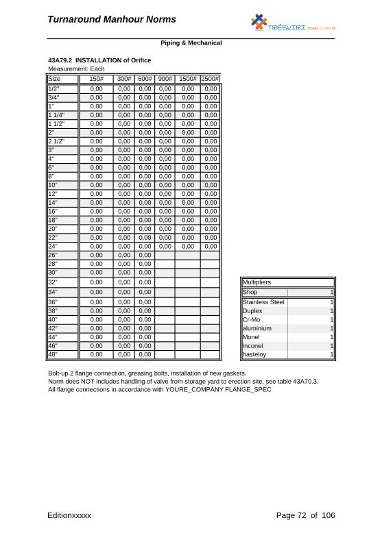
Turnaround Manhour Norms
Measurement: Each
Size 150# 300# 600# 900# 1500# 2500#]
1/2" 0,00 0,00 0,00 0,00 0,00 0,00
3/4" 0,00 0,00 0,00 0,00 0,00 0,00
1" 0,00 0,00 0,00 0,00 0,00 0,00
1 1/4" 0,00 0,00 0,00 0,00 0,00 0,00
1 1/2" 0,00 0,00 0,00 0,00 0,00 0,00
2" 0,00 0,00 0,00 0,00 0,00 0,00
2 1/2" 0,00 0,00 0,00 0,00 0,00 0,00
3" 0,00 0,00 0,00 0,00 0,00 0,00
4" 0,00 0,00 0,00 0,00 0,00 0,00
6" 0,00 0,00 0,00 0,00 0,00 0,00
8" 0,00 0,00 0,00 0,00 0,00 0,00
10" 0,00 0,00 0,00 0,00 0,00 0,00
12" 0,00 0,00 0,00 0,00 0,00 0,00
14" 0,00 0,00 0,00 0,00 0,00 0,00
16" 0,00 0,00 0,00 0,00 0,00 0,00
18" 0,00 0,00 0,00 0,00 0,00 0,00
20" 0,00 0,00 0,00 0,00 0,00 0,00
22" 0,00 0,00 0,00 0,00 0,00 0,00
24" 0,00 0,00 0,00 0,00 0,00 0,00
26" 0,00 0,00 0,00
28" 0,00 0,00 0,00
30" 0,00 0,00 0,00
32" 0,00 0,00 0,00 Multipliers
34" 0,00 0,00 0,00 Shop 1
36" 0,00 0,00 0,00 Stainless Steel 1
38" 0,00 0,00 0,00 Duplex 1
40" 0,00 0,00 0,00 Cr-Mo 1
42" 0,00 0,00 0,00 aluminium 1
44" 0,00 0,00 0,00 Monel 1
46" 0,00 0,00 0,00 Inconel 1
48" 0,00 0,00 0,00 hasteloy 1
Piping & Mechanical
43A79.2 INSTALLATION of Orifice
Bolt-up 2 flange connection, greasing bolts, installation of new gaskets.
Norm does NOT includes handling of valve from storage yard to erection site, see table 43A70.3.
All flange connections in accordance with YOURE_COMPANY FLANGE_SPEC
Editionxxxxx Page 72 of 106
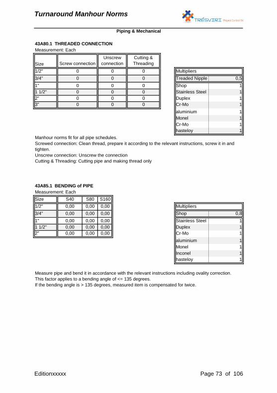
Turnaround Manhour Norms
43A80.1 THREADED CONNECTION
Measurement: Each
Size
1/2" Multipliers
3/4" Treaded Nipple 0,5
1" Shop 1
1 1/2" Stainless Steel 1
2" Duplex 1
3" Cr-Mo 1
aluminium 1
Monel 1
Cr-Mo 1
hasteloy 1
Measurement: Each
Size S40 S80 S160
1/2" 0,00 0,00 0,00 Multipliers
3/4" 0,00 0,00 0,00 Shop 0,8
1" 0,00 0,00 0,00 Stainless Steel 1
1 1/2" 0,00 0,00 0,00 Duplex 1
2" 0,00 0,00 0,00 Cr-Mo 1
aluminium 1
Monel 1
Inconel 1
hasteloy 1
Piping & Mechanical
43A85.1 BENDING of PIPE
Measure pipe and bend it in accordance with the relevant instructions including ovality correction.
This factor applies to a bending angle of <= 135 degrees.
If the bending angle is > 135 degrees, measured item is compensated for twice.
Manhour norms fit for all pipe schedules.
Screwed connection: Clean thread, prepare it according to the relevant instructions, screw it in and
tighten.
Unscrew connection: Unscrew the connection
Cutting & Threading: Cutting pipe and making thread only
Screw connection
0
0
0
0
0
0
Unscrew
connection
0
0
0
0
0
0
Cutting &
Threading
0
0
0
0
0
0
Editionxxxxx Page 73 of 106
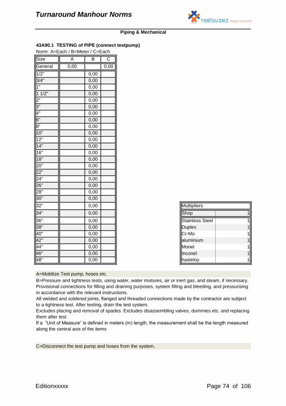
Turnaround Manhour Norms
Norm: A=Each / B=Meter / C=Each
Size A B C
General 0,00 0,00
1/2" 0,00
3/4" 0,00
1" 0,00
1 1/2" 0,00
2" 0,00
3" 0,00
4" 0,00
6" 0,00
8" 0,00
10" 0,00
12" 0,00
14" 0,00
16" 0,00
18" 0,00
20" 0,00
22" 0,00
24" 0,00
26" 0,00
28" 0,00
30" 0,00
32" 0,00 Multipliers
34" 0,00 Shop 1
36" 0,00 Stainless Steel 1
38" 0,00 Duplex 1
40" 0,00 Cr-Mo 1
42" 0,00 aluminium 1
44" 0,00 Monel 1
46" 0,00 Inconel 1
48" 0,00 hasteloy 1
43A90.1 TESTING of PIPE (connect testpump)
Piping & Mechanical
C=Disconnect the test pump and hoses from the system.
A=Mobilize Test pump, hoses etc.
B=Pressure and tightness tests, using water, water mixtures, air or inert gas, and steam, if necessary.
Provisional connections for filling and draining purposes, system filling and bleeding, and pressurising
in accordance with the relevant instructions.
All welded and soldered joints, flanged and threaded connections made by the contractor are subject
to a tightness test. After testing, drain the test system.
Excludes placing and removal of spades. Excludes disassembling valves, dummies etc. and replacing
them after test.
If a “Unit of Measure” is defined in meters (m) length, the measurement shall be the length measured
along the central axis of the items
Editionxxxxx Page 74 of 106

Turnaround Manhour Norms
Electrical
&
Intrumentation
Editionxxxxx Page 75 of 106

Turnaround Manhour Norms
Multipliers (correction factors)
Measurement
IMPORTANT:
All Electrical & Instrumantation Tables marked up wit * includes the codes for:
Installation : 45A0x.xx
Disassembly : 45A3x.xx
Demolish : 45A4x.xx
For Example
Installation : 45A01.10
Disassembly : 45A31.10
Demolish : 45A41.10
Electrical & Instrumentation
The Labour norms are based on working at the YOURE_COMPANY location. For work in a shop
condition you have to use the multiplier for shop work.
Other disciplines
Supporting disciplines, such as scaffolding construction, insulation work, transport (unless stated
otherwise), lifting do not form part of the man-hour norms.
The units of measurement to be used shall be as stated in the Labour norms and is defined within the
preambles.
For a work item a “Unit of Measure” is defined in meters (m) length, the measurement shall be the
length measured along the central axis of the items.
All items of work are measured net as fixed in position and no allowance is made in the quantities for
cut and waste.
Editionxxxxx Page 76 of 106
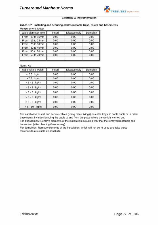
Turnaround Manhour Norms
Measurement: Meter
Norm: Kg
Electrical & Instrumentation
cable diameter from Install Disassembly
From 00 to 16mm 0,00 0,00
Demolish
0,00
45A01.10* Installing and securing cables in Cable trays, Ducts and basements
cable with a weight Install Disassembly Demolish
< 0.5 kg/m 0,00 0,00 0,00
From 16 to 23mm 0,00 0,00
From 23 to 30mm 0,00 0,00
From 30 to 40mm 0,00 0,00
From 40 to 50mm 0,00 0,00
From 50 to 70mm 0,00 0,00
0,00
0,00
0,00
0,00
0,00
> 0.5 kg/m 0,00 0,00 0,00
> 1 - 2 kg/m 0,00 0,00 0,00
> 2 - 3 kg/m 0,00 0,00 0,00
> 3 - 5 kg/m 0,00 0,00 0,00
> 6 - 8 kg/m 0,00 0,00 0,00
> 5 - 6 kg/m 0,00 0,00 0,00
> 8 - 10 kg/m 0,00 0,00 0,00
For installation: Install and secure cables (using cable fixings) on cable trays, in cable ducts or in cable
basements, includes bringing the cable to and from the place where the work is carried out.
For disassembly: Remove elements of the installation in such a way that the removed materials can
be re-used (after cleaning if necessary).
For demolition: Remove elements of the installation, which will not be re-used and take these
materials to a suitable disposal site.
Editionxxxxx Page 77 of 106
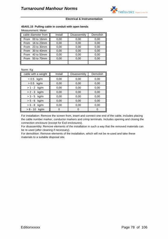
Turnaround Manhour Norms
Measurement: Meter
Norm: Kg
From 23 to 30mm 0,00 0,00 0,00
From 30 to 40mm 0,00 0,00 0,00
From 40 to 50mm 0,00 0,00 0,00
From 50 to 70mm 0,00 0,00 0,00
45A01.15 Pulling cable in conduit with open bends
cable diameter from Install Disassembly Demolish
From 00 to 16mm 0,00 0,00 0,00
From 16 to 23mm 0,00 0,00 0,00
cable with a weight Install Disassembly Demolish
< 0.5 kg/m 0,00 0,00 0,00
> 0.5 kg/m 0,00 0,00 0,00
> 1 - 2 kg/m 0,00 0,00 0,00
> 2 - 3 kg/m 0,00 0,00 0,00
> 3 - 5 kg/m 0,00 0,00 0,00
> 5 - 6 kg/m 0,00 0,00 0,00
> 6 - 8 kg/m 0,00 0,00 0,00
> 8 - 10 kg/m 0 0 0
For installation: Remove the screen from, insert and connect one end of the cable, includes placing
the cable number marker, conductor markers and crimp terminals. Includes opening and closing the
connection enclosure (except for Exd enclosures).
For disassembly: Remove elements of the installation in such a way that the removed materials can
be re-used (after cleaning if necessary).
For demolition: Remove elements of the installation, which will not be re-used and take these
materials to a suitable disposal site.
Electrical & Instrumentation
Editionxxxxx Page 78 of 106

Turnaround Manhour Norms
Measurement: Meter
Norm: Kg
45A01.20 Underground cable installation
cable diameter from Install Disassembly Demolish
From 00 to 16mm 0,00 0,00 0,00
From 16 to 23mm 0,00 0,00 0,00
From 23 to 30mm 0,00 0,00 0,00
From 30 to 40mm 0,00 0,00 0,00
From 40 to 50mm 0,00 0,00 0,00
From 50 to 70mm 0,00 0,00 0,00
cable with a weight Install Disassembly Demolish
< 0.5 kg/m 0,00 0,00 0,00
> 0.5 kg/m 0,00 0,00 0,00
> 1 - 2 kg/m 0,00 0,00 0,00
> 2 - 3 kg/m 0,00 0,00 0,00
> 3 - 5 kg/m 0,00 0,00 0,00
> 5 - 6 kg/m 0,00 0,00 0,00
> 6 - 8 kg/m 0,00 0,00 0,00
> 8 - 10 kg/m 0 0 0
For installation: Remove the screen from, insert and connect one end of the cable, includes placing
the cable number marker, conductor markers and crimp terminals. Includes opening and closing the
connection enclosure (except for Exd enclosures).
For disassembly: Remove elements of the installation in such a way that the removed materials can
be re-used (after cleaning if necessary).
For demolition: Remove elements of the installation, which will not be re-used and take these
materials to a suitable disposal site.
Electrical & Instrumentation
Editionxxxxx Page 79 of 106
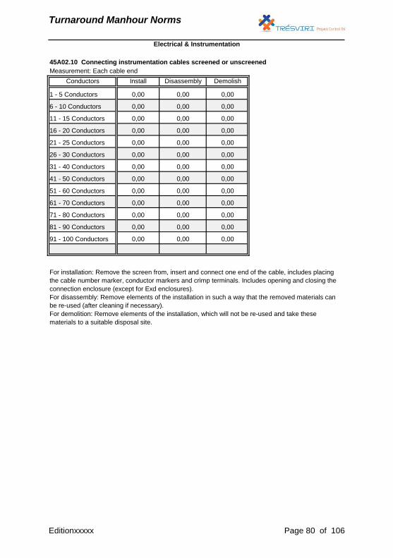
Turnaround Manhour Norms
Measurement: Each cable end
45A02.10 Connecting instrumentation cables screened or unscreened
Conductors Install Disassembly Demolish
1 - 5 Conductors 0,00 0,00 0,00
6 - 10 Conductors 0,00 0,00 0,00
11 - 15 Conductors 0,00 0,00 0,00
16 - 20 Conductors 0,00 0,00 0,00
21 - 25 Conductors 0,00 0,00 0,00
0,00
91 - 100 Conductors 0,00 0,00 0,00
26 - 30 Conductors 0,00 0,00 0,00
31 - 40 Conductors 0,00 0,00 0,00
41 - 50 Conductors 0,00 0,00 0,00
For installation: Remove the screen from, insert and connect one end of the cable, includes placing
the cable number marker, conductor markers and crimp terminals. Includes opening and closing the
connection enclosure (except for Exd enclosures).
For disassembly: Remove elements of the installation in such a way that the removed materials can
be re-used (after cleaning if necessary).
For demolition: Remove elements of the installation, which will not be re-used and take these
materials to a suitable disposal site.
Electrical & Instrumentation
51 - 60 Conductors 0,00 0,00 0,00
61 - 70 Conductors 0,00 0,00 0,00
71 - 80 Conductors 0,00 0,00 0,00
81 - 90 Conductors 0,00 0,00
Editionxxxxx Page 80 of 106
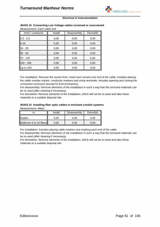
Turnaround Manhour Norms
Measurement: Each cable end
Measurement: Meter
45A02.15 Connecting Low Voltage cables screened or unscreened
mm2 / conductor Install Disassembly Demolish
0.3 - 2.5 0,00 0,00 0,00
4-10 0,00 0,00 0,00
16 - 25 0,00 0,00 0,00
35 - 50 0,00 0,00 0,00
70 - 120 0,00 0,00 0,00
150 - 185 0,00 0,00 0,00
m Install Disassembly Demolish
Duplex 0,00 0,00 0,00
Multicore 6 to 24 fibers 0,00 0,00 0,00
For installation: Remove the screen from, insert and connect one end of the cable, includes placing
the cable number marker, conductor markers and crimp terminals. Includes opening and closing the
connection enclosure (except for Exd enclosures).
For disassembly: Remove elements of the installation in such a way that the removed materials can
be re-used (after cleaning if necessary).
For demolition: Remove elements of the installation, which will not be re-used and take these
materials to a suitable disposal site.
45A03.10 Installing fiber optic cables in enclosed conduit systems
Up to 240 0,00 0,00 0,00
For installation: Includes placing cable markers and marking each end of the cable
For disassembly: Remove elements of the installation in such a way that the removed materials can
be re-used (after cleaning if necessary).
For demolition: Remove elements of the installation, which will not be re-used and take these
materials to a suitable disposal site.
Electrical & Instrumentation
Editionxxxxx Page 81 of 106
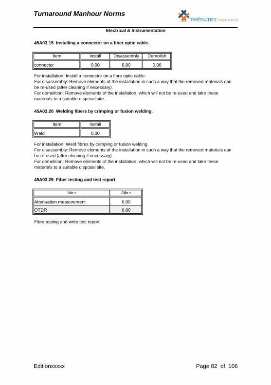
Turnaround Manhour Norms
For installation: Install a connector on a fibre optic cable.
For disassembly: Remove elements of the installation in such a way that the removed materials can
be re-used (after cleaning if necessary).
For demolition: Remove elements of the installation, which will not be re-used and take these
materials to a suitable disposal site.
45A03.20 Welding fibers by crimping or fusion welding.
Item Install
Weld 0,00
For installation: Weld fibres by crimping or fusion welding
For disassembly: Remove elements of the installation in such a way that the removed materials can
be re-used (after cleaning if necessary).
For demolition: Remove elements of the installation, which will not be re-used and take these
materials to a suitable disposal site.
45A03.25 Fiber testing and test report
Item Install Disassembly Demolish
45A03.15 Installing a connector on a fiber optic cable.
connector 0,00 0,00 0,00
Fibre testing and write test report
/fiber
0,00
0,00
fiber
Attenuation measurement
OTDR
Electrical & Instrumentation
Editionxxxxx Page 82 of 106

Turnaround Manhour Norms
45A03.30 Connecting connectorised duplex fiber optic cable to equipment
Item Install Disassembly Demolish
Cable end 0,00 0,00 0,00
For installation: Lay up, secure, tying up and connect duplex fibre optic cable to equipment
For disassembly: Remove elements of the installation in such a way that the removed materials can
be re-used (after cleaning if necessary).
For demolition: Remove elements of the installation, which will not be re-used and take these
materials to a suitable disposal site.
Electrical & Instrumentation
Editionxxxxx Page 83 of 106
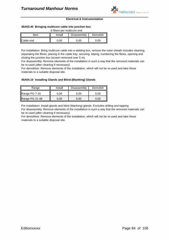
Turnaround Manhour Norms
6 fibers per multicore end
45A03.40 Bringing multicore cable into junction box
Item Install Disassembly Demolish
Cable end 0,00 0,00 0,00
For installation: Bring multicore cable into a welding box, remove the outer sheath includes cleaning,
separating the fibres, placing in the cable tray, securing, tidying, numbering the fibres, opening and
closing the junction box (screen removed over 5 m).
For disassembly: Remove elements of the installation in such a way that the removed materials can
be re-used (after cleaning if necessary).
For demolition: Remove elements of the installation, which will not be re-used and take these
materials to a suitable disposal site.
45A04.10 Installing Glands and Blind (Blanking) Glands
Disassembly
0,00
0,00
For installation: Install glands and blind (blanking) glands. Excludes drilling and tapping
For disassembly: Remove elements of the installation in such a way that the removed materials can
be re-used (after cleaning if necessary).
For demolition: Remove elements of the installation, which will not be re-used and take these
materials to a suitable disposal site.
Range Install Demolish
Range PG 7-16 0,00 0,00
Range PG 21-48 0,00 0,00
Electrical & Instrumentation
Editionxxxxx Page 84 of 106
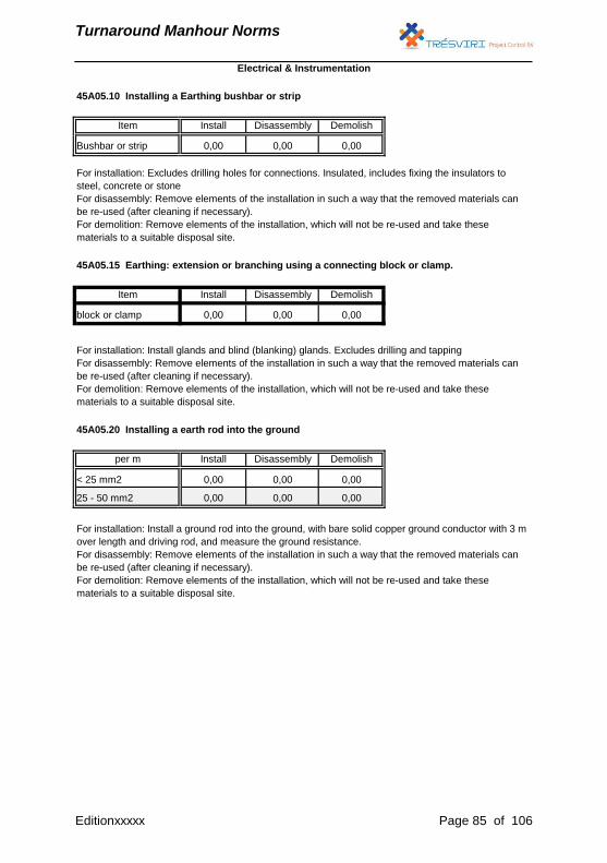
Turnaround Manhour Norms
0,00 0,00 0,00
For installation: Install a ground rod into the ground, with bare solid copper ground conductor with 3 m
over length and driving rod, and measure the ground resistance.
For disassembly: Remove elements of the installation in such a way that the removed materials can
be re-used (after cleaning if necessary).
For demolition: Remove elements of the installation, which will not be re-used and take these
materials to a suitable disposal site.
45A05.10 Installing a Earthing bushbar or strip
Item Install Disassembly Demolish
Bushbar or strip 0,00 0,00 0,00
For installation: Excludes drilling holes for connections. Insulated, includes fixing the insulators to
steel, concrete or stone
For disassembly: Remove elements of the installation in such a way that the removed materials can
be re-used (after cleaning if necessary).
For demolition: Remove elements of the installation, which will not be re-used and take these
materials to a suitable disposal site.
45A05.15 Earthing: extension or branching using a connecting block or clamp.
Item Install Disassembly Demolish
block or clamp 0,00 0,00 0,00
Electrical & Instrumentation
For installation: Install glands and blind (blanking) glands. Excludes drilling and tapping
For disassembly: Remove elements of the installation in such a way that the removed materials can
be re-used (after cleaning if necessary).
For demolition: Remove elements of the installation, which will not be re-used and take these
materials to a suitable disposal site.
45A05.20 Installing a earth rod into the ground
per m Install Disassembly Demolish
< 25 mm2 0,00 0,00 0,00
25 - 50 mm2
Editionxxxxx Page 85 of 106
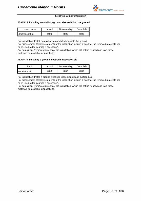
Turnaround Manhour Norms
45A05.25 Installing an auxiliary ground electrode into the ground
norm per m Install Disassembly Demolish
Electrode 2.5m 0,00 0,00 0,00
For installation: Install an auxiliary ground electrode into the ground
For disassembly: Remove elements of the installation in such a way that the removed materials can
be re-used (after cleaning if necessary).
For demolition: Remove elements of the installation, which will not be re-used and take these
materials to a suitable disposal site.
45A05.30 Installing a ground electrode inspection pit.
Each Install Disassembly Demolish
Inspection pit 0,00 0,00 0,00
For installation: Install a ground electrode inspection pit and surface box
For disassembly: Remove elements of the installation in such a way that the removed materials can
be re-used (after cleaning if necessary).
For demolition: Remove elements of the installation, which will not be re-used and take these
materials to a suitable disposal site.
Electrical & Instrumentation
Editionxxxxx Page 86 of 106
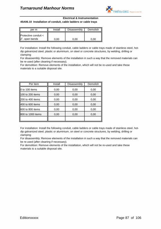
Turnaround Manhour Norms
For installation: Install the following conduit, cable ladders or cable trays made of stainless steel, hot-
dip galvanized steel, plastic or aluminium, on steel or concrete structures, by welding, drilling or
clamping
For disassembly: Remove elements of the installation in such a way that the removed materials can
be re-used (after cleaning if necessary).
For demolition: Remove elements of the installation, which will not be re-used and take these
materials to a suitable disposal site.
Per item Install Disassembly Demolish
0 to 100 items 0,00 0,00 0,00
100 to 200 items 0,00 0,00 0,00
200 to 400 items 0,00 0,00 0,00
45A06.10 Installation of conduit, cable ladders or cable trays
per m Install Disassembly Demolish
Protective conduit <
2”, open bends 0,00 0,00 0,00
For installation: Install the following conduit, cable ladders or cable trays made of stainless steel, hot-
dip galvanized steel, plastic or aluminium, on steel or concrete structures, by welding, drilling or
clamping
For disassembly: Remove elements of the installation in such a way that the removed materials can
be re-used (after cleaning if necessary).
For demolition: Remove elements of the installation, which will not be re-used and take these
materials to a suitable disposal site.
Electrical & Instrumentation
400 to 600 items 0,00 0,00 0,00
600 to 800 items 0,00 0,00 0,00
800 to 1000 items 0,00 0,00 0,00
Editionxxxxx Page 87 of 106
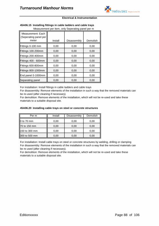
Turnaround Manhour Norms
Measurement per item, only Seperating panel per m
45A06.15 Installing fittings in cable ladders and cable trays
Measurement: Each
(Seperating panel per
meter Install Disassembly Demolish
Fittings 0-100 mm 0,00 0,00 0,00
Fittings 100-200mm 0,00 0,00 0,00
Fittings 200-400mm 0,00 0,00 0,00
Fittings 400 - 600mm 0,00 0,00 0,00
Fittings 600-800mm 0,00 0,00 0,00
Fittings 800-1000mm 0,00 0,00 0,00
Separating panel 0,00 0,00 0,00
For installation: Install fittings in cable ladders and cable trays
For disassembly: Remove elements of the installation in such a way that the removed materials can
be re-used (after cleaning if necessary).
For demolition: Remove elements of the installation, which will not be re-used and take these
materials to a suitable disposal site.
End panel 0-1000mm 0,00 0,00 0,00
45A06.20 Installing cable trays on steel or concrete structures
Per m Install Disassembly Demolish
For installation: Install cable trays on steel or concrete structures by welding, drilling or clamping
For disassembly: Remove elements of the installation in such a way that the removed materials can
be re-used (after cleaning if necessary).
For demolition: Remove elements of the installation, which will not be re-used and take these
materials to a suitable disposal site.
0 to 70 mm 0,00 0,00 0,00
70 to 150 mm 0,00 0,00 0,00
150 to 300 mm 0,00 0,00 0,00
300 to 500 mm 0,00 0,00 0,00
Electrical & Instrumentation
Editionxxxxx Page 88 of 106
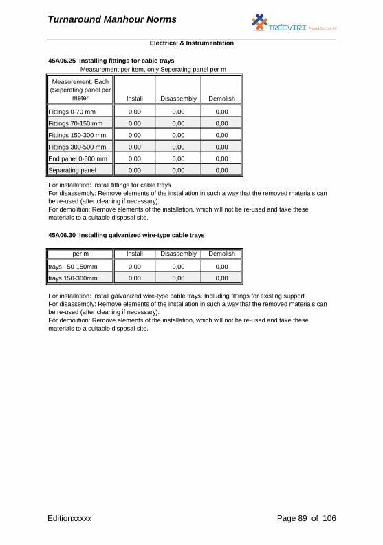
Turnaround Manhour Norms
Measurement per item, only Seperating panel per m
Measurement: Each
(Seperating panel per
meter Install Disassembly Demolish
Fittings 0-70 mm 0,00 0,00 0,00
45A06.25 Installing fittings for cable trays
Fittings 70-150 mm 0,00 0,00 0,00
Install Disassembly Demolish
trays 50-150mm 0,00 0,00 0,00
trays 150-300mm 0,00 0,00 0,00
Fittings 150-300 mm 0,00 0,00 0,00
Fittings 300-500 mm 0,00 0,00 0,00
End panel 0-500 mm 0,00 0,00 0,00
Separating panel 0,00 0,00 0,00
For installation: Install galvanized wire-type cable trays. Including fittings for existing support
For disassembly: Remove elements of the installation in such a way that the removed materials can
be re-used (after cleaning if necessary).
For demolition: Remove elements of the installation, which will not be re-used and take these
materials to a suitable disposal site.
Electrical & Instrumentation
For installation: Install fittings for cable trays
For disassembly: Remove elements of the installation in such a way that the removed materials can
be re-used (after cleaning if necessary).
For demolition: Remove elements of the installation, which will not be re-used and take these
materials to a suitable disposal site.
45A06.30 Installing galvanized wire-type cable trays
per m
Editionxxxxx Page 89 of 106
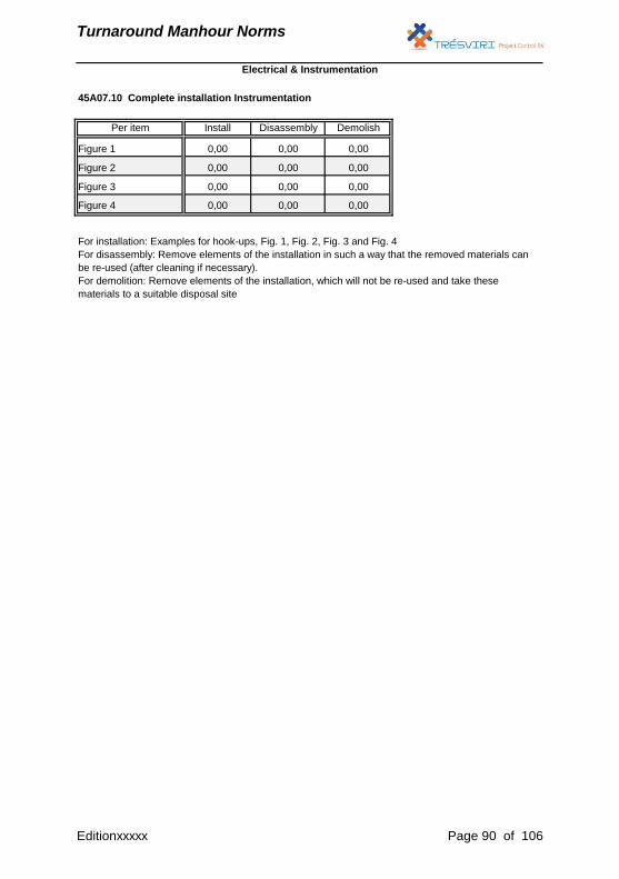
Turnaround Manhour Norms
Figure 4 0,00 0,00 0,00
For installation: Examples for hook-ups, Fig. 1, Fig. 2, Fig. 3 and Fig. 4
For disassembly: Remove elements of the installation in such a way that the removed materials can
be re-used (after cleaning if necessary).
For demolition: Remove elements of the installation, which will not be re-used and take these
materials to a suitable disposal site
Electrical & Instrumentation
45A07.10 Complete installation Instrumentation
Per item Install Disassembly Demolish
Figure 1 0,00 0,00 0,00
Figure 2 0,00 0,00 0,00
Figure 3 0,00 0,00 0,00
Editionxxxxx Page 90 of 106
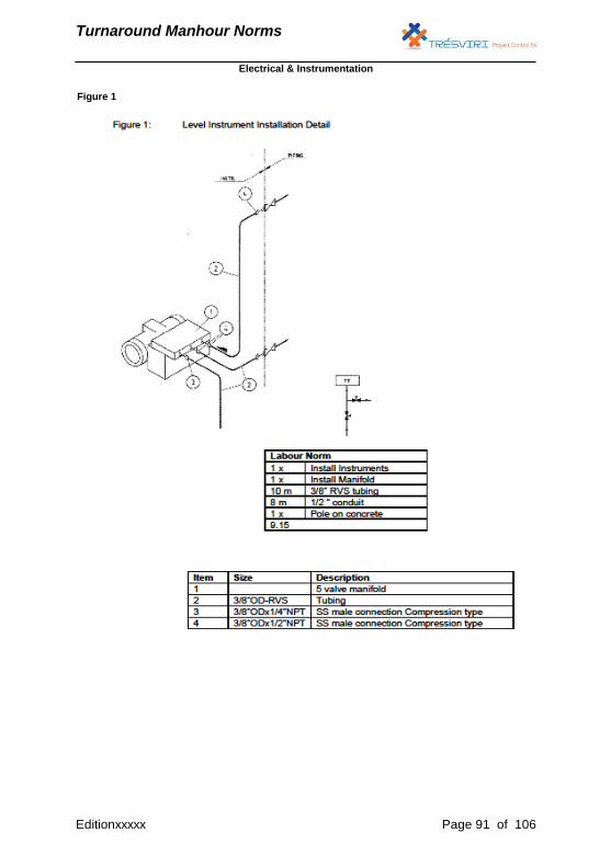
Turnaround Manhour Norms
Electrical & Instrumentation
Figure 1
Editionxxxxx Page 91 of 106
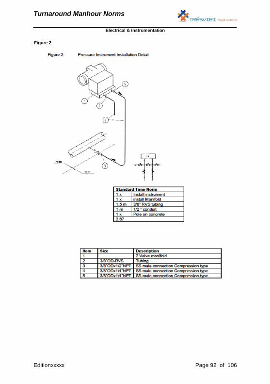
Turnaround Manhour Norms
Electrical & Instrumentation
Figure 2
Editionxxxxx Page 92 of 106
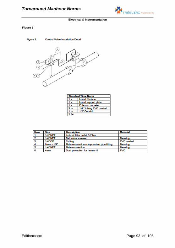
Turnaround Manhour Norms
Electrical & Instrumentation
Figure 3
Editionxxxxx Page 93 of 106
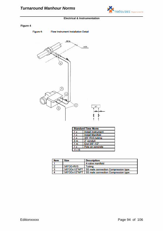
Turnaround Manhour Norms
Electrical & Instrumentation
Figure 4
Editionxxxxx Page 94 of 106

Turnaround Manhour Norms
Electrical & Instrumentation
45A08.10 Installing Impulse, air and supply lines (L<3m / PVC coated copper)
L<3m (Norm per m) Install Disassembly Demolish
1/8” 3 mm 0,00 0,00 0,00
1/4” 6 mm 0,00 0,00 0,00
3/8” 10 mm 0,00 0,00 0,00
1/2" 12 mm 0,00 0,00 0,00
3/4” 19 mm 0,00 0,00 0,00
For installation: Install impulse, air and supply lines and instrument lines (tubing) on existing supports,
includes the installation of spacers (‘Stauff klem’), Install and connect couplings, making bends, and
carry out a leak test.
A distinction is made between uninterrupted runs < 3 m and uninterrupted runs > 3 m
For disassembly: Remove elements of the installation in such a way that the removed materials can
be re-used (after cleaning if necessary).
For demolition: Remove elements of the installation, which will not be re-used and take these
materials to a suitable disposal site.
45A08.15 Installing Impulse, air and supply lines (L<3m / monel)
L<3m (Norm per m) Install Disassembly Demolish
1/8” 3 mm 0,00 0,00 0,00
1/4” 6 mm 0,00 0,00 0,00
3/8” 10 mm 0,00 0,00 0,00
1/2" 12 mm 0,00 0,00 0,00
3/4” 19 mm 0,00 0,00 0,00
For installation: Install impulse, air and supply lines and instrument lines (tubing) on existing supports,
includes the installation of spacers (‘Stauff klem’), Install and connect couplings, making bends, and
carry out a leak test.
A distinction is made between uninterrupted runs < 3 m and uninterrupted runs > 3 m
For disassembly: Remove elements of the installation in such a way that the removed materials can
be re-used (after cleaning if necessary).
For demolition: Remove elements of the installation, which will not be re-used and take these
materials to a suitable disposal site.
Editionxxxxx Page 95 of 106
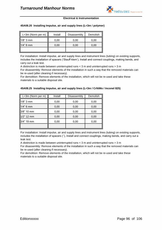
Turnaround Manhour Norms
1/8” 3 mm 0,00 0,00 0,00
1/4” 6 mm 0,00 0,00 0,00
45A08.20 Installing Impulse, air and supply lines (L<3m / polymer)
L<3m (Norm per m) Install Disassembly Demolish
Electrical & Instrumentation
For installation: Install impulse, air and supply lines and instrument lines (tubing) on existing supports,
includes the installation of spacers (‘Stauff klem’), Install and connect couplings, making bends, and
carry out a leak test.
A distinction is made between uninterrupted runs < 3 m and uninterrupted runs > 3 m
For disassembly: Remove elements of the installation in such a way that the removed materials can
be re-used (after cleaning if necessary).
For demolition: Remove elements of the installation, which will not be re-used and take these
materials to a suitable disposal site.
45A08.25 Installing Impulse, air and supply lines (L<3m / CrNiMo / Inconel 825)
L<3m (Norm per m) Install Disassembly Demolish
1/8” 3 mm 0,00 0,00 0,00
1/4” 6 mm 0,00 0,00 0,00
3/8” 10 mm 0,00 0,00 0,00
1/2" 12 mm 0,00 0,00 0,00
3/4” 19 mm 0,00 0,00 0,00
For installation: Install impulse, air and supply lines and instrument lines (tubing) on existing supports,
includes the installation of spacers (‘’), Install and connect couplings, making bends, and carry out a
leak test.
A distinction is made between uninterrupted runs < 3 m and uninterrupted runs > 3 m
For disassembly: Remove elements of the installation in such a way that the removed materials can
be re-used (after cleaning if necessary).
For demolition: Remove elements of the installation, which will not be re-used and take these
materials to a suitable disposal site.
Editionxxxxx Page 96 of 106
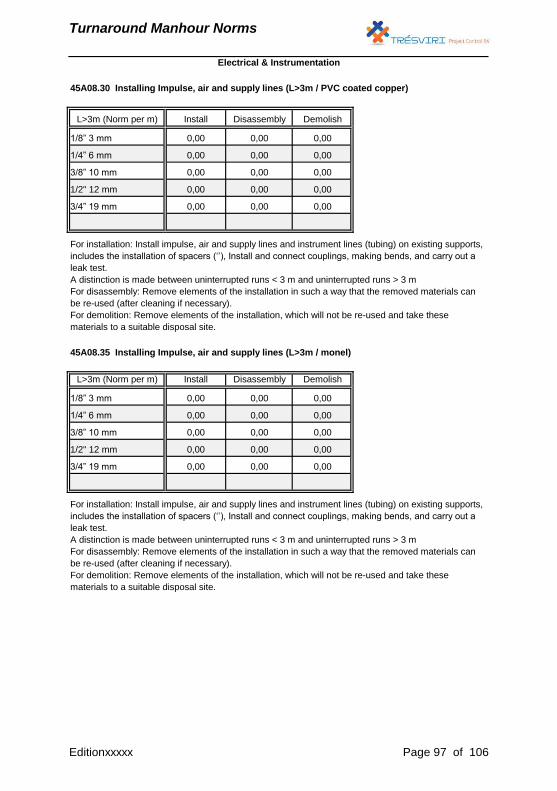
Turnaround Manhour Norms
Electrical & Instrumentation
45A08.30 Installing Impulse, air and supply lines (L>3m / PVC coated copper)
L>3m (Norm per m) Install Disassembly Demolish
1/8” 3 mm 0,00 0,00 0,00
1/4” 6 mm 0,00 0,00 0,00
3/8” 10 mm 0,00 0,00 0,00
1/2" 12 mm 0,00 0,00 0,00
3/4” 19 mm 0,00 0,00 0,00
For installation: Install impulse, air and supply lines and instrument lines (tubing) on existing supports,
includes the installation of spacers (‘’), Install and connect couplings, making bends, and carry out a
leak test.
A distinction is made between uninterrupted runs < 3 m and uninterrupted runs > 3 m
For disassembly: Remove elements of the installation in such a way that the removed materials can
be re-used (after cleaning if necessary).
For demolition: Remove elements of the installation, which will not be re-used and take these
materials to a suitable disposal site.
45A08.35 Installing Impulse, air and supply lines (L>3m / monel)
L>3m (Norm per m) Install Disassembly Demolish
1/8” 3 mm 0,00 0,00 0,00
1/4” 6 mm 0,00 0,00 0,00
3/8” 10 mm 0,00 0,00 0,00
1/2" 12 mm 0,00 0,00 0,00
3/4” 19 mm 0,00 0,00 0,00
For installation: Install impulse, air and supply lines and instrument lines (tubing) on existing supports,
includes the installation of spacers (‘’), Install and connect couplings, making bends, and carry out a
leak test.
A distinction is made between uninterrupted runs < 3 m and uninterrupted runs > 3 m
For disassembly: Remove elements of the installation in such a way that the removed materials can
be re-used (after cleaning if necessary).
For demolition: Remove elements of the installation, which will not be re-used and take these
materials to a suitable disposal site.
Editionxxxxx Page 97 of 106
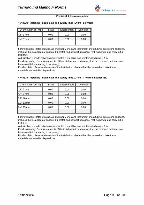
Turnaround Manhour Norms
Electrical & Instrumentation
45A08.40 Installing Impulse, air and supply lines (L>3m / polymer)
L>3m (Norm per m) Install Disassembly Demolish
1/8” 3 mm 0,00 0,00 0,00
1/4” 6 mm 0,00 0,00 0,00
For installation: Install impulse, air and supply lines and instrument lines (tubing) on existing supports,
includes the installation of spacers (‘’), Install and connect couplings, making bends, and carry out a
leak test.
A distinction is made between uninterrupted runs < 3 m and uninterrupted runs > 3 m
For disassembly: Remove elements of the installation in such a way that the removed materials can
be re-used (after cleaning if necessary).
For demolition: Remove elements of the installation, which will not be re-used and take these
materials to a suitable disposal site.
45A08.45 Installing Impulse, air and supply lines (L>3m / CrNiMo / Inconel 825)
L>3m (Norm per m) Install Disassembly Demolish
1/8” 3 mm 0,00 0,00 0,00
1/4” 6 mm 0,00 0,00 0,00
3/8” 10 mm 0,00 0,00 0,00
1/2" 12 mm 0,00 0,00 0,00
3/4” 19 mm 0,00 0,00 0,00
For installation: Install impulse, air and supply lines and instrument lines (tubing) on existing supports,
includes the installation of spacers (‘’), Install and connect couplings, making bends, and carry out a
leak test.
A distinction is made between uninterrupted runs < 3 m and uninterrupted runs > 3 m
For disassembly: Remove elements of the installation in such a way that the removed materials can
be re-used (after cleaning if necessary).
For demolition: Remove elements of the installation, which will not be re-used and take these
materials to a suitable disposal site.
Editionxxxxx Page 98 of 106
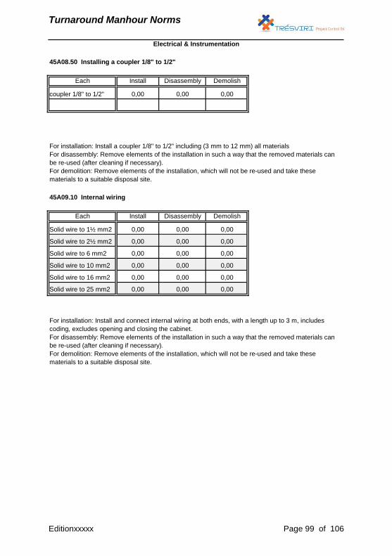
Turnaround Manhour Norms
45A08.50 Installing a coupler 1/8" to 1/2"
Each Install Disassembly Demolish
coupler 1/8" to 1/2" 0,00 0,00 0,00
For installation: Install a coupler 1/8" to 1/2" including (3 mm to 12 mm) all materials
For disassembly: Remove elements of the installation in such a way that the removed materials can
be re-used (after cleaning if necessary).
For demolition: Remove elements of the installation, which will not be re-used and take these
materials to a suitable disposal site.
45A09.10 Internal wiring
Each Install Disassembly Demolish
Solid wire to 1½ mm2 0,00 0,00 0,00
Solid wire to 2½ mm2 0,00 0,00 0,00
Solid wire to 6 mm2 0,00 0,00 0,00
Solid wire to 10 mm2 0,00 0,00 0,00
Solid wire to 16 mm2 0,00 0,00 0,00
Solid wire to 25 mm2 0,00 0,00 0,00
For installation: Install and connect internal wiring at both ends, with a length up to 3 m, includes
coding, excludes opening and closing the cabinet.
For disassembly: Remove elements of the installation in such a way that the removed materials can
be re-used (after cleaning if necessary).
For demolition: Remove elements of the installation, which will not be re-used and take these
materials to a suitable disposal site.
Electrical & Instrumentation
Editionxxxxx Page 99 of 106
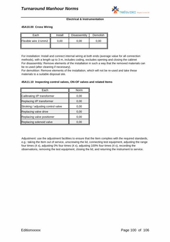
Turnaround Manhour Norms
Flexible wire 1½mm2 0,00 0,00 0,00
For installation: Install and connect internal wiring at both ends (average value for all connection
methods), with a length up to 3 m, includes coding, excludes opening and closing the cabinet
For disassembly: Remove elements of the installation in such a way that the removed materials can
be re-used (after cleaning if necessary).
For demolition: Remove elements of the installation, which will not be re-used and take these
materials to a suitable disposal site.
45A11.10 Inspecting control valves, ON-OF valves and related Items
Norm
0,00
45A10.00 Cross Wiring
Each Install Disassembly Demolish
Electrical & Instrumentation
Adjustment: use the adjustment facilities to ensure that the Item complies with the required standards,
e.g.: taking the Item out of service, unscrewing the lid, connecting test equipment, adjusting the range
four times (4 x), adjusting 0% four times (4 x), adjusting 100% four times (4 x), recording the
observations, removing the test equipment, closing the lid, and returning the instrument to service.
Each
Calibrating I/P transformer
Replacing I/P transformer
Stroking / adjusting control valve
Replacing valve drive
Replacing valve positioner
Replacing solenoid valve
0,00
0,00
0,00
0,00
0,00
Editionxxxxx Page 100 of 106
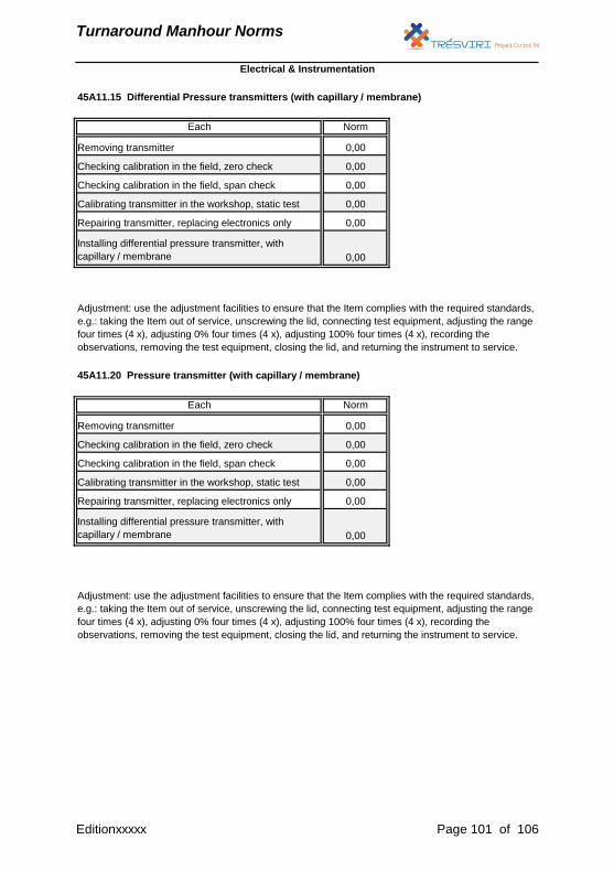
Turnaround Manhour Norms
Adjustment: use the adjustment facilities to ensure that the Item complies with the required standards,
e.g.: taking the Item out of service, unscrewing the lid, connecting test equipment, adjusting the range
four times (4 x), adjusting 0% four times (4 x), adjusting 100% four times (4 x), recording the
observations, removing the test equipment, closing the lid, and returning the instrument to service.
Norm
0,00
0,00
0,00
0,00
0,00
0,00
Checking calibration in the field, zero check
Installing differential pressure transmitter, with
capillary / membrane
Each
Removing transmitter
Checking calibration in the field, span check
Calibrating transmitter in the workshop, static test
Repairing transmitter, replacing electronics only
45A11.15 Differential Pressure transmitters (with capillary / membrane)
Electrical & Instrumentation
45A11.20 Pressure transmitter (with capillary / membrane)
Each Norm
Removing transmitter 0,00
Checking calibration in the field, zero check 0,00
Checking calibration in the field, span check 0,00
Calibrating transmitter in the workshop, static test 0,00
Repairing transmitter, replacing electronics only 0,00
Installing differential pressure transmitter, with
capillary / membrane 0,00
Adjustment: use the adjustment facilities to ensure that the Item complies with the required standards,
e.g.: taking the Item out of service, unscrewing the lid, connecting test equipment, adjusting the range
four times (4 x), adjusting 0% four times (4 x), adjusting 100% four times (4 x), recording the
observations, removing the test equipment, closing the lid, and returning the instrument to service.
Editionxxxxx Page 101 of 106
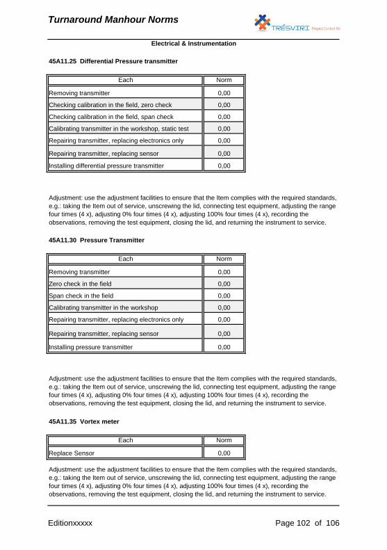
Turnaround Manhour Norms
45A11.25 Differential Pressure transmitter
Electrical & Instrumentation
Each Norm
Removing transmitter 0,00
Checking calibration in the field, zero check 0,00
Checking calibration in the field, span check 0,00
Calibrating transmitter in the workshop, static test 0,00
Repairing transmitter, replacing electronics only 0,00
Installing differential pressure transmitter 0,00
Adjustment: use the adjustment facilities to ensure that the Item complies with the required standards,
e.g.: taking the Item out of service, unscrewing the lid, connecting test equipment, adjusting the range
four times (4 x), adjusting 0% four times (4 x), adjusting 100% four times (4 x), recording the
observations, removing the test equipment, closing the lid, and returning the instrument to service.
45A11.35 Vortex meter
Each Norm
Repairing transmitter, replacing sensor 0,00
Adjustment: use the adjustment facilities to ensure that the Item complies with the required standards,
e.g.: taking the Item out of service, unscrewing the lid, connecting test equipment, adjusting the range
four times (4 x), adjusting 0% four times (4 x), adjusting 100% four times (4 x), recording the
observations, removing the test equipment, closing the lid, and returning the instrument to service.
Replace Sensor 0,00
Adjustment: use the adjustment facilities to ensure that the Item complies with the required standards,
e.g.: taking the Item out of service, unscrewing the lid, connecting test equipment, adjusting the range
four times (4 x), adjusting 0% four times (4 x), adjusting 100% four times (4 x), recording the
observations, removing the test equipment, closing the lid, and returning the instrument to service.
Repairing transmitter, replacing sensor 0,00
Installing pressure transmitter 0,00
45A11.30 Pressure Transmitter
Each Norm
Removing transmitter 0,00
Zero check in the field 0,00
Span check in the field 0,00
Calibrating transmitter in the workshop 0,00
Repairing transmitter, replacing electronics only 0,00
Editionxxxxx Page 102 of 106
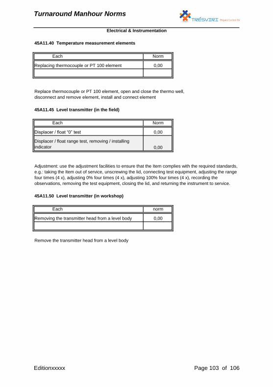
Turnaround Manhour Norms
45A11.40 Temperature measurement elements
Each Norm
0,00
Replace thermocouple or PT 100 element, open and close the thermo well,
disconnect and remove element, install and connect element
Replacing thermocouple or PT 100 element
45A11.45 Level transmitter (in the field)
Each Norm
Remove the transmitter head from a level body
Displacer / float range test, removing / installing
indicator
Displacer / float “0” test 0,00
0,00
Adjustment: use the adjustment facilities to ensure that the Item complies with the required standards,
e.g.: taking the Item out of service, unscrewing the lid, connecting test equipment, adjusting the range
four times (4 x), adjusting 0% four times (4 x), adjusting 100% four times (4 x), recording the
observations, removing the test equipment, closing the lid, and returning the instrument to service.
45A11.50 Level transmitter (in workshop)
Each norm
Removing the transmitter head from a level body 0,00
Electrical & Instrumentation
Editionxxxxx Page 103 of 106
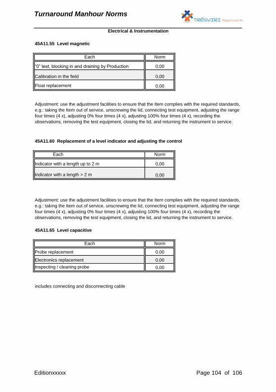
Turnaround Manhour Norms
45A11.55 Level magnetic
Each Norm
“0” test, blocking in and draining by Production 0,00
Calibration in the field 0,00
Norm
Indicator with a length up to 2 m 0,00
Indicator with a length > 2 m 0,00
Adjustment: use the adjustment facilities to ensure that the Item complies with the required standards,
e.g.: taking the Item out of service, unscrewing the lid, connecting test equipment, adjusting the range
four times (4 x), adjusting 0% four times (4 x), adjusting 100% four times (4 x), recording the
observations, removing the test equipment, closing the lid, and returning the instrument to service.
45A11.65 Level capacitive
Each Norm
Probe replacement 0,00
Electronics replacement
Electrical & Instrumentation
Float replacement 0,00
Adjustment: use the adjustment facilities to ensure that the Item complies with the required standards,
e.g.: taking the Item out of service, unscrewing the lid, connecting test equipment, adjusting the range
four times (4 x), adjusting 0% four times (4 x), adjusting 100% four times (4 x), recording the
observations, removing the test equipment, closing the lid, and returning the instrument to service.
45A11.60 Replacement of a level indicator and adjusting the control
Each
0,00
Inspecting / cleaning probe 0,00
includes connecting and disconnecting cable
Editionxxxxx Page 104 of 106
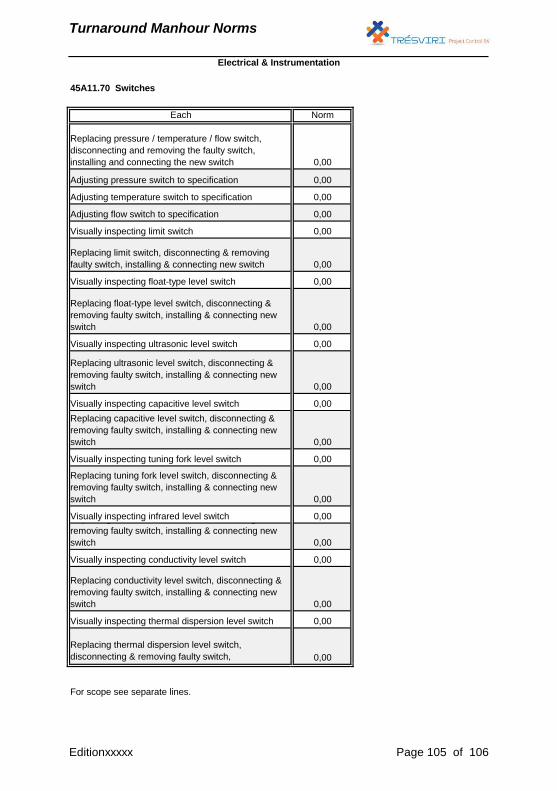
Turnaround Manhour Norms
0,00
Visually inspecting ultrasonic level switch 0,00
Replacing capacitive level switch, disconnecting &
removing faulty switch, installing & connecting new
switch 0,00
0,00
Replacing float-type level switch, disconnecting &
removing faulty switch, installing & connecting new
switch
Electrical & Instrumentation
Replacing thermal dispersion level switch,
disconnecting & removing faulty switch, 0,00
For scope see separate lines.
Replacing ultrasonic level switch, disconnecting &
removing faulty switch, installing & connecting new
switch 0,00
Visually inspecting capacitive level switch 0,00
Replacing tuning fork level switch, disconnecting &
removing faulty switch, installing & connecting new
switch 0,00
Visually inspecting infrared level switch 0,00
Adjusting pressure switch to specification 0,00
Visually inspecting conductivity level switch 0,00
Replacing conductivity level switch, disconnecting &
removing faulty switch, installing & connecting new
switch 0,00
Visually inspecting thermal dispersion level switch 0,00
0,00
Replacing limit switch, disconnecting & removing
faulty switch, installing & connecting new switch 0,00
Visually inspecting float-type level switch
45A11.70 Switches
Each Norm
Replacing pressure / temperature / flow switch,
disconnecting and removing the faulty switch,
installing and connecting the new switch 0,00
Replacing infrared level switch, disconnecting &
removing faulty switch, installing & connecting new
switch 0,00
Visually inspecting tuning fork level switch
Adjusting temperature switch to specification 0,00
Adjusting flow switch to specification 0,00
Visually inspecting limit switch 0,00
Editionxxxxx Page 105 of 106

Turnaround Manhour Norms
Electrical & Instrumentation
Editionxxxxx Page 106 of 106