Embed Size (px)
Citation preview
.J
Turn-to-Turn Short in Collared Coil DC0305 During Inital Keying Attempt*
Steve Delchamps January 29, 1991
TS-SSC 91- 021
During the initial keying attempt of DC0305, a turn-to-tum short occurred. The circumstances are described in detail in this memo. The recommended dis-assembly procedure will be described in a further memo.
Installation in Keying Press: DC0305 was installed in the keying press on January 28, 1991. There were initially seven malfunctioning strain gages (see Table 1.) As shown in the.table, four of these gages had been disfunctional on January 25, 1991. The other three gages had problems only after the coil was inserted in the tooling and rolled into the press.
Two of the newly disfunctional gages were found to have disconnected wires at the 24-pin connectors on the outside of the press. These connectors were resoldered and the gages functioned properly subsequently. The third gage was examined, and it was decided that its problem was more serious. Since it was a compensating gage, it was decided to continue with the keying procedure.
Initial Keying Attempt: At 0838 on January 29, 1991, the pump pressure was raised to 1000 psi. Data from strain gages, press L VDT'sl, and upper and lower coil resistance measurements2 were recorded at this pressure value. Feeler gage information was recorded only at odd multiples of 1000 psi throughout the keying procedure. Data were taken at 2000, 3000, 4000, 5000, 6000, and 6800 pump psi as shown in Table 2.
At 0921, as the pressure was being raised from 6000 to 7000 psi, an alarm sounded which indicated that the upper and lower coil resistances were different by more than 1 %. In particular, the upper and lower coil resistances were 3.212 Q and 3.157 n respectively (1.77% different.) The initial resistance values were 3.215 Wand 3.208 Q, indicating that the lower coil had dropped in resistance by 51 m.O, while the upper coil had only changed by 3 mO., a change within the systematic errors of the measurement.
The pump pressure was halted at 6800 psi when the alarm sounded, and was not changed until after all of the measurements had been made to localize the short as described below. However, over a period of several hours, the pump pressure did decay slightly, as shown in Figure 1.
By 0939, the resistance of the lower coil had decreased further to 3.120 Q. It remained at this value or within several mQ of this value until the pump pressure was taken down as described below.
* I would like to acknowledge the important assistance of Dean Connely, Denny Gaw, Wayne Koska, Donna Kubik, Scott Lockwood, Bill Robodczik, Reed Rihel, Brian Smith, and Dan Smith, in performing these measurements.

Diagnosis of the Problem: Since there are 36 turns in each coil, and since the initial lower coil resistance was 3.208 il, the loss of a single turn of resistance would cause a decrease of about 89 mil. Therefore, a tum-to-turn short was suspected immediately.
It was recommended that the lower coil ramp splice pre-forms be separated and the inner and outer lower coils measured individually. When this was done, it was found that the lower inner coil resistance had dropped by 87 mil from its most recently measured value. (See Table 3.)
Since the short appeared to be in the lower inner coil, it was recommended that the voltage taps be used to further localize the short. Table 4 shows the resistances measured3 between the preform end of the coil and a set of taps on the lower inner coil. The first set of measurements was taken at 1015, the second at 1040. Other than the slightly larger than expected value of the lOA - 9A resistance, these numbers looked normal.
Also shown in Table 4 for interest are the fractional differences between resistance measurements made with and without the "temperature correction" invoked on the Valhalla meter. In general, the measured resistance without temperature correction was a little more than .5% higher.
A measurement was then made of the resistance between the lead end of the lower inner coil and the 9A voltage tap. The value of 687 mil was less than the expected value of 774 mil4 by 87 mn. It was therefore concluded that the most likely location of the tum-to-turn short was in the uninstrumented portion of the lower inner coil, that is, somewhere between the 9A tap and the lead end of the coil.
Release of Pump Pressure: Once the above data had been taken, it was decided to release the pump pressure in 1000 psi steps, to see whether the short would go away or would remain. Table 5 shows the coil resistance data taken as the pump pressure was decreased.
Somewhere between 1000 psi and 0 psi, the short dissapeared. The pump pressure was then raised to 350 psi, the minimum pressure needed for any contact between the upper tooling and the collared coil. The pressure was then taken to 500 psi, and raised in increments of 50 psi, as shown in Table 5. A 550 psi, a slow decrease in the resistance of the lower coil was detected. At 650 psi, the alarm sounded indicating that the short had reappeared. The press was then dumped again, and the short went away.
Removal of DC0305 from Keying Press: On the afternoon of January 29, 1991, DC0305 was removed from the keying press and laid in an upside-down position on a table in ICB to prepare for removal of the collar packs and the lower coils.
Distribution: J. Carson W. Koska L. Peters G. Pewitt D. Smith J. Strait D. Warner
Notes
lThree L VDT's had been mounted on either side of the keying press since DC0304 was keyed. These were zeroed with the press completely closed before the attempt to key DC0305 was made. All six L VDT's are read out by the Hewlett-Packard computer and readings in inches are automatically printed to the screen.
2During keying, the upper inner and upper outer coils have their ramp splice preforms c-clamped together, allowing a measurement of the total upper coil resistance to be made. The lower inner and outer coils are treated the same. The resistances are monitored with Valhalla meters (.100 A current, 4-wire measurement). The data from the Valhallas is read out by the Hewlett-Packard computer, and the upper and lower coil resistances are periodically printed to the screen.
3These measurements were made with a separate Valhalla meter (100 mA, 4-wire measurement.)
4The expected value was obtained by finding the difference between the most recent (1-23-91) measurements of the 9A - 16B tap resistance and the full lower inner coil resistance: 1375 mQ- 601mQ=774 m!'l
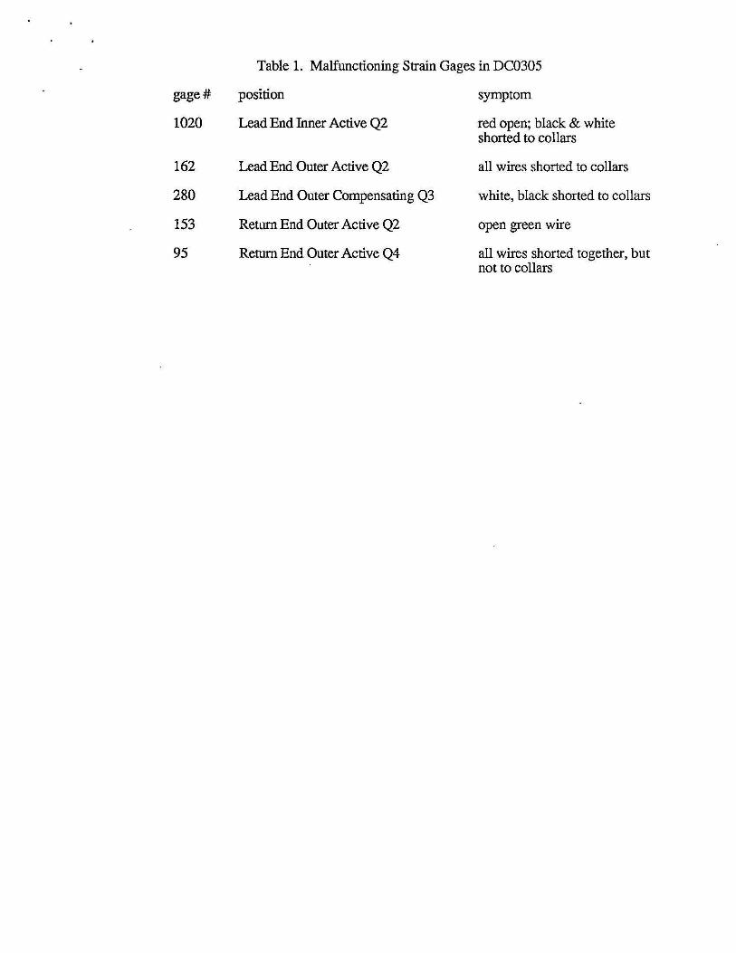
Table 1. Malfunctioning Strain Gages in DC0305
gage# position symptom
1020 Lead End Inner Active Q2 red open; black & white shorted to collars
162 Lead End Outer Active Q2 all wires shorted to collars
280 Lead End Outer Compensating Q3 white, black shorted to collars
153 Return End Outer Active Q2 open green wire
95 Return End Outer Active Q4 all wires shorted together, but not to collars
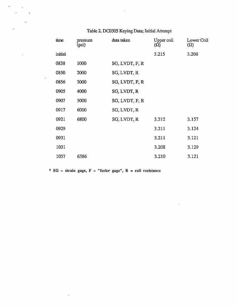
Table 2. DC0305 Keying Data; Initial Attempt
time pressure data taken Upper coil Lower Coil (psi) (Q) (Q)
initial 3.215 3.208
0838 1000 SG, LVDT, F, R
0850 2000 SG,LVDT,R
0856 3000 SG, L VDT, F, R
0905 4000 SG,LVDT,R
0907 5000 SG, LVDT, F, R
0917 6000 SG,LVDT,R
0921 6800 SG,LVDT,R 3.212 3.157
0929 3.211 3.124
0931 3.211 3.121
1031 3.208 3.129
1057 6386 3.210 3.121
* SG = strain gage, F = "feeler gage", R = coil resistance
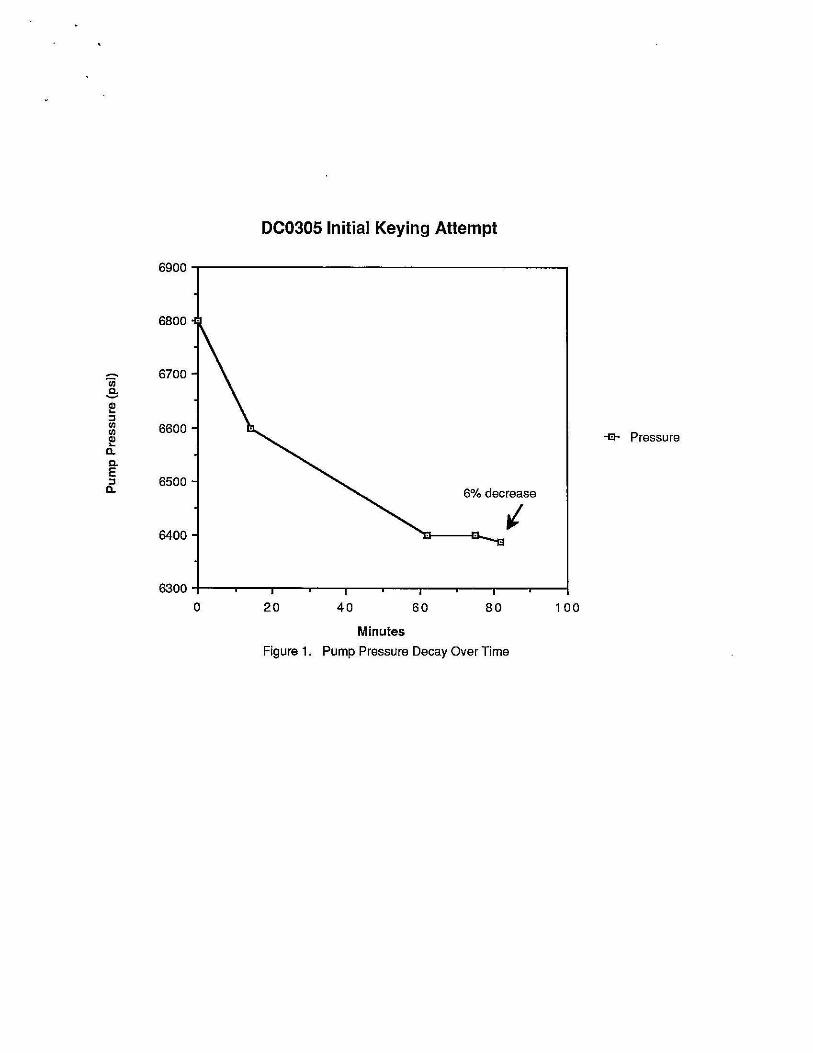
DC0305 Initial Keying Attempt
- 6700 ·a; .3: dl ... ::l l/j 6600 l/j -e- Pressure ~ 0. Q.. E
6500 ::l Cl.. 6% decrease
ti 6400
6300-+-___,--___, ........ ___,-----..,___,.--___,....-----..,...,_---..,-.----..,-.----..,-.----..,--1
0 20 40 60 80 100
Minutes
Figure 1. Pump Pressure Decay Over Time

Table 3. D0)305 Keying Data; Quarter Coil Resistances
1-23-91 During Keying Attempt (mQ) (mQ)
Upper Inner 1379 1384
Lower Inner 1375 1288
Upper Outer 1829 1834
Lower Outer 1833 1837
Table 4. DC0305 Keying Data; Lower Inner Coil Voltage Tap Resistances
(16B to indicated tap position)
position 1-23-91 1-29-91 (10:14) 1-29-91 (10:40) /1TC/R (mQ) (mQ) (mQ) (%)
16A 1.8 1.7 1.9 0
15A 87.3 87.2 87.4 .57
14A 172.6 172.5 172.7 .57
13A 258.0 257.7 257.8 .62
12A 343.7 343.1 343.1 .64
lOB 512.1 511.8 .66
lOA 515.3 513.1 513.3 .64
9B 598.0 596.5 .67
9A 601.0 599.7 596.5 .65
9A-OA -------- 687.2 .65
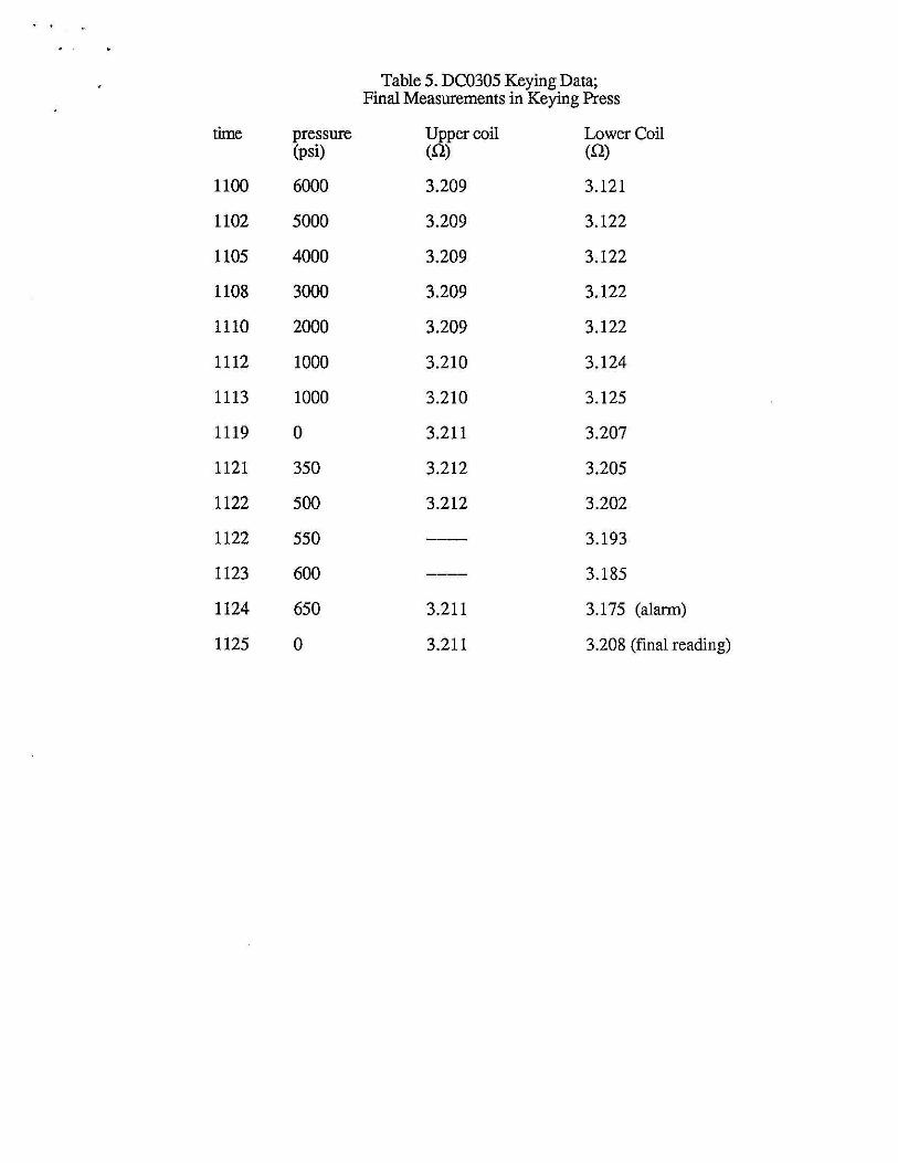
Table 5. DC0305 Keying Data; Final Measurements in Keying Press
time pressure Upper coil Lower Coil (psi) (Q) (Q)
1100 6000 3.209 3.121
1102 5000 3.209 3.122
1105 4000 3.209 3.122
1108 3000 3.209 3.122
1110 2000 3.209 3.122
1112 1000 3.210 3.124
1113 1000 3.210 3.125
1119 0 3.211 3.207
1121 350 3.212 3.205
1122 500 3.212 3.202
1122 550 3.193
1123 600 3.185
1124 650 3.211 3.175 (alarm)
1125 0 3.211 3.208 (final reading)