Embed Size (px)
Citation preview
Introduction Geometrical features Coordinate system and reference frames Characteristics Internal flow features
Turbomachinery & Turbulence.Lecture 1: Introduction to turbomachinery.
F. Ravelet
Laboratoire DynFluid, Arts et Metiers-ParisTech
March 10, 2015
Introduction Geometrical features Coordinate system and reference frames Characteristics Internal flow features
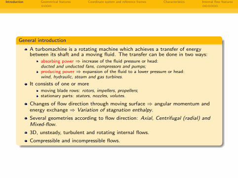
General introduction
A turbomachine is a rotating machine which achieves a transfer of energybetween its shaft and a moving fluid. The transfer can be done in two ways:
absorbing power ⇒ increase of the fluid pressure or head:ducted and unducted fans, compressors and pumps;producing power ⇒ expansion of the fluid to a lower pressure or head:wind, hydraulic, steam and gas turbines.
It consists of one or moremoving blade rows: rotors, impellers, propellers;stationary parts: stators, nozzles, volutes.
Changes of flow direction through moving surface ⇒ angular momentum andenergy exchange ⇒ Variation of stagnation enthalpy.
Several geometries according to flow direction: Axial, Centrifugal (radial) andMixed-flow.
3D, unsteady, turbulent and rotating internal flows.
Compressible and incompressible flows.
Introduction Geometrical features Coordinate system and reference frames Characteristics Internal flow features
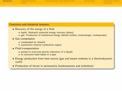
Functions and industrial domains
Recovery of the energy of a fluidliquid: Hydraulic potential energy recovery (dams)gas: Production of mechanical energy (dental turbine, turbocharger, turbopumps)
Gas compressioncompressed air networkautomotive internal combustion engine
Fluid transportationpumps to overcome gravity (elevation of a liquid)to overcome head losses in a pipe
Energy production from heat source (gas and steam turbines in a thermodynamiccycle)
Production of thrust in aeronautics (turboreactors and turbofans)
Introduction Geometrical features Coordinate system and reference frames Characteristics Internal flow features
Overview
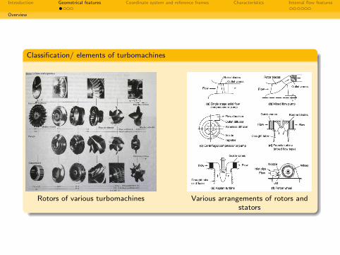
Classification/ elements of turbomachines
Rotors of various turbomachines Various arrangements of rotors andstators
Introduction Geometrical features Coordinate system and reference frames Characteristics Internal flow features
Examples
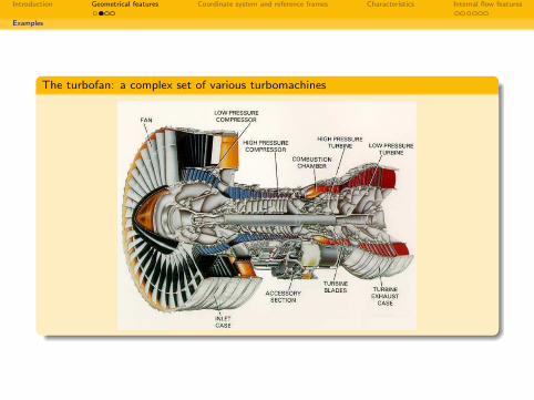
The turbofan: a complex set of various turbomachines
Introduction Geometrical features Coordinate system and reference frames Characteristics Internal flow features
Examples
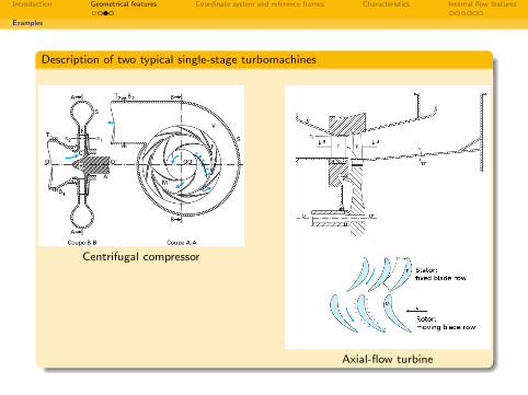
Description of two typical single-stage turbomachines
Centrifugal compressor
Axial-flow turbine
Introduction Geometrical features Coordinate system and reference frames Characteristics Internal flow features
Examples
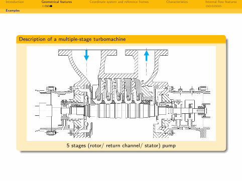
Description of a multiple-stage turbomachine
5 stages (rotor/ return channel/ stator) pump
Introduction Geometrical features Coordinate system and reference frames Characteristics Internal flow features
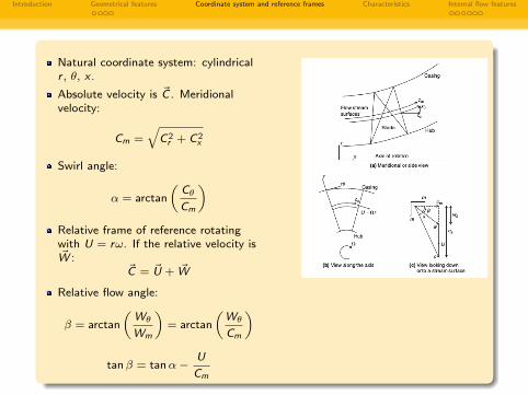
Natural coordinate system: cylindricalr , θ, x .
Absolute velocity is ~C . Meridionalvelocity:
Cm =√
C 2r + C 2
x
Swirl angle:
α = arctan
(Cθ
Cm
)Relative frame of reference rotatingwith U = rω. If the relative velocity is~W :
~C = ~U + ~W
Relative flow angle:
β = arctan
(Wθ
Wm
)= arctan
(Wθ
Cm
)
tanβ = tanα−U
Cm
Introduction Geometrical features Coordinate system and reference frames Characteristics Internal flow features
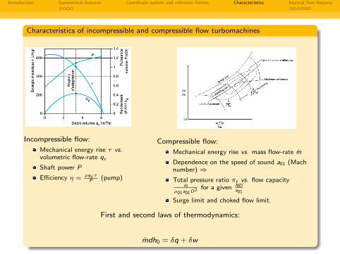
Characteristics of incompressible and compressible flow turbomachines
Incompressible flow:
Mechanical energy rise τ vs.volumetric flow-rate qv
Shaft power P
Efficiency η = ρqv τP (pump)
Compressible flow:
Mechanical energy rise vs. mass flow-rate m
Dependence on the speed of sound a01 (Machnumber) ⇒Total pressure ratio πt vs. flow capacity
mρ01a01D2 for a given ND
a01
Surge limit and choked flow limit.
First and second laws of thermodynamics:
mdh0 = δq + δw
Introduction Geometrical features Coordinate system and reference frames Characteristics Internal flow features
Unsteadiness
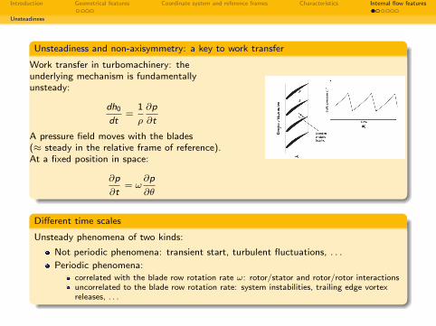
Unsteadiness and non-axisymmetry: a key to work transfer
Work transfer in turbomachinery: theunderlying mechanism is fundamentallyunsteady:
dh0
dt=
1
ρ
∂p
∂t
A pressure field moves with the blades(≈ steady in the relative frame of reference).At a fixed position in space:
∂p
∂t= ω
∂p
∂θ
Different time scales
Unsteady phenomena of two kinds:
Not periodic phenomena: transient start, turbulent fluctuations, . . .
Periodic phenomena:correlated with the blade row rotation rate ω: rotor/stator and rotor/rotor interactionsuncorrelated to the blade row rotation rate: system instabilities, trailing edge vortexreleases, . . .
Introduction Geometrical features Coordinate system and reference frames Characteristics Internal flow features
Unsteadiness
Rotor/stator interaction
-In a stage, one blade row is downstream of the other (!)
-For a blade row rotation rate ω, with Z the number of blades, l the chord length andCm the meridional velocity:
Blade passing time scale: tbpf = 2πZω
Convective time scale: tc = lCm
Reduced frequency: f = tctbpf
= Zωl2πCm
f � 1: convective phenomena are dominant ⇒ quasi-steady flow.f � 1: periodical perturbations are dominant ⇒ unsteady flow.
Introduction Geometrical features Coordinate system and reference frames Characteristics Internal flow features
Turbulence vs. large-scale flow
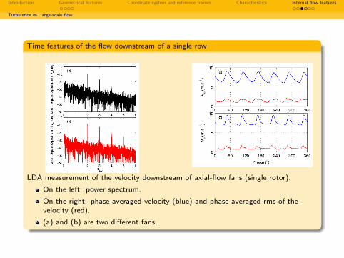
Time features of the flow downstream of a single row
LDA measurement of the velocity downstream of axial-flow fans (single rotor).
On the left: power spectrum.
On the right: phase-averaged velocity (blue) and phase-averaged rms of thevelocity (red).
(a) and (b) are two different fans.
Introduction Geometrical features Coordinate system and reference frames Characteristics Internal flow features
Turbulence vs. large-scale flow
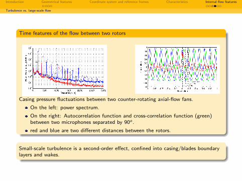
Time features of the flow between two rotors
Casing pressure fluctuations between two counter-rotating axial-flow fans.
On the left: power spectrum.
On the right: Autocorrelation function and cross-correlation function (green)between two microphones separated by 90o .
red and blue are two different distances between the rotors.
Small-scale turbulence is a second-order effect, confined into casing/blades boundarylayers and wakes.
Introduction Geometrical features Coordinate system and reference frames Characteristics Internal flow features
Three-dimensional flow
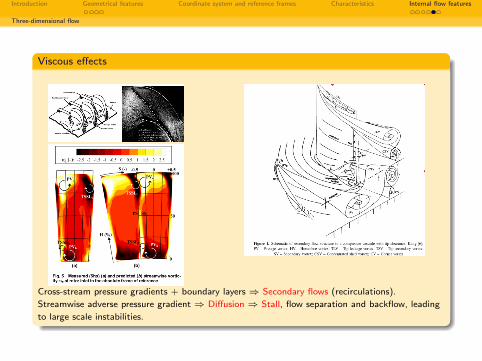
Viscous effects
Cross-stream pressure gradients + boundary layers ⇒ Secondary flows (recirculations).
Streamwise adverse pressure gradient ⇒ Diffusion ⇒ Stall, flow separation and backflow, leading
to large scale instabilities.
Introduction Geometrical features Coordinate system and reference frames Characteristics Internal flow features
Instabilities
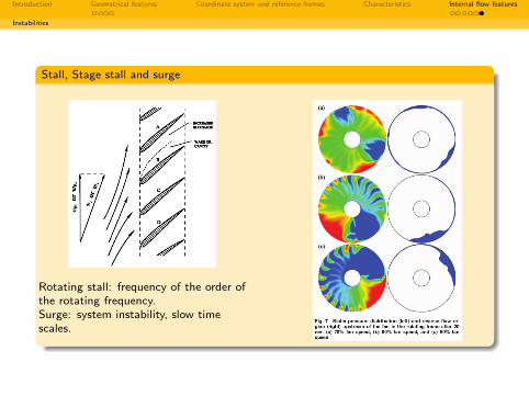
Stall, Stage stall and surge
Rotating stall: frequency of the order ofthe rotating frequency.Surge: system instability, slow timescales.