Embed Size (px)
Citation preview

Robert C. HendricksGlenn Research Center, Cleveland, Ohio
Raymond E. ChuppGeneral-Electric Global Research Center, Niskayuna, New York
Scott B. LattimeUniversity of Akron, Akron, Ohio
Bruce M. SteinetzGlenn Research Center, Cleveland, Ohio
Turbomachine Interface Sealing
NASA/TM—2005-213633
April 2005
https://ntrs.nasa.gov/search.jsp?R=20050175891 2020-04-13T22:45:40+00:00Z
The NASA STI Program Office . . . in Profile
Since its founding, NASA has been dedicated tothe advancement of aeronautics and spacescience. The NASA Scientific and TechnicalInformation (STI) Program Office plays a key partin helping NASA maintain this important role.
The NASA STI Program Office is operated byLangley Research Center, the Lead Center forNASA’s scientific and technical information. TheNASA STI Program Office provides access to theNASA STI Database, the largest collection ofaeronautical and space science STI in the world.The Program Office is also NASA’s institutionalmechanism for disseminating the results of itsresearch and development activities. These resultsare published by NASA in the NASA STI ReportSeries, which includes the following report types:
• TECHNICAL PUBLICATION. Reports ofcompleted research or a major significantphase of research that present the results ofNASA programs and include extensive dataor theoretical analysis. Includes compilationsof significant scientific and technical data andinformation deemed to be of continuingreference value. NASA’s counterpart of peer-reviewed formal professional papers buthas less stringent limitations on manuscriptlength and extent of graphic presentations.
• TECHNICAL MEMORANDUM. Scientificand technical findings that are preliminary orof specialized interest, e.g., quick releasereports, working papers, and bibliographiesthat contain minimal annotation. Does notcontain extensive analysis.
• CONTRACTOR REPORT. Scientific andtechnical findings by NASA-sponsoredcontractors and grantees.
• CONFERENCE PUBLICATION. Collectedpapers from scientific and technicalconferences, symposia, seminars, or othermeetings sponsored or cosponsored byNASA.
• SPECIAL PUBLICATION. Scientific,technical, or historical information fromNASA programs, projects, and missions,often concerned with subjects havingsubstantial public interest.
• TECHNICAL TRANSLATION. English-language translations of foreign scientificand technical material pertinent to NASA’smission.
Specialized services that complement the STIProgram Office’s diverse offerings includecreating custom thesauri, building customizeddatabases, organizing and publishing researchresults . . . even providing videos.
For more information about the NASA STIProgram Office, see the following:
• Access the NASA STI Program Home Pageat http://www.sti.nasa.gov
• E-mail your question via the Internet [email protected]
• Fax your question to the NASA AccessHelp Desk at 301–621–0134
• Telephone the NASA Access Help Desk at301–621–0390
• Write to: NASA Access Help Desk NASA Center for AeroSpace Information 7121 Standard Drive Hanover, MD 21076
Robert C. HendricksGlenn Research Center, Cleveland, Ohio
Raymond E. ChuppGeneral-Electric Global Research Center, Niskayuna, New York
Scott B. LattimeUniversity of Akron, Akron, Ohio
Bruce M. SteinetzGlenn Research Center, Cleveland, Ohio
Turbomachine Interface Sealing
NASA/TM—2005-213633
April 2005
National Aeronautics andSpace Administration
Glenn Research Center
Prepared for theInternational Conference on Metallurgical Coatings and Thin Filmssponsored by the AVS Science & TechnologySan Diego, California, May 2–6, 2005
Available from
NASA Center for Aerospace Information7121 Standard DriveHanover, MD 21076
National Technical Information Service5285 Port Royal RoadSpringfield, VA 22100
This report is a preprint of a paper intended for presentation at a conference. Becauseof changes that may be made before formal publication, this preprint is made
available with the understanding that it will not be cited or reproduced without thepermission of the author.
Trade names or manufacturers’ names are used in this report foridentification only. This usage does not constitute an officialendorsement, either expressed or implied, by the National
Aeronautics and Space Administration.
Available electronically at http://gltrs.grc.nasa.gov
NASA/TM—2005-213633 1
Turbomachine Interface Sealing
Robert C. Hendricks National Aeronautics and Space Administration
Glenn Research Center Cleveland, Ohio 44135
Raymond E. Chupp
General-Electric Global Research Center Niskayuna, New York 12309
Scott B. Lattime*
University of Akron Akron, Ohio 44325
Bruce M. Steinetz
National Aeronautics and Space Administration Glenn Research Center Cleveland, Ohio 44135
Abstract
Sealing interfaces and coatings, like lubricants, are sacrificial, giving up their integrity for the benefit of the component. Clearance control is a major issue in power systems turbomachine design and operational life. Sealing becomes the most cost-effective way to enhance system performance. Coatings, films, and combined use of both metals and ceramics play a major role in maintaining interface clearances in turbomachine sealing and component life. This paper focuses on conventional and innovative materials and design practices for sealing interfaces.
Introduction
Interface sealing controls turbomachine leakages, coolant flows, and dynamics and are the most cost-effective method of enhancing performance. Materials control how well and how long these interfaces will be effective in doing their job. These interface materials are subjected to abrasion, erosion, oxidation, incursive rubs, foreign object damage, and deposits. They are also exposed to extremes in thermal, mechanical, and aerodynamic loadings including positive and negative strain ranges, large case distortions and impact loadings. No one material can effectively satisfy these variations throughout a turbomachine and must be properly tailored to maintain the interface. Most seals are coating composites fabricated on substrates that are coated with sacrificial
* NASA Resident Research Associate at Glenn Research Center.
NASA/TM—2005-213633 2
materials, which can be readily refurbished either in situ or by removal. Design requirements are addressed in sections following.
Turbomachine Characteristics
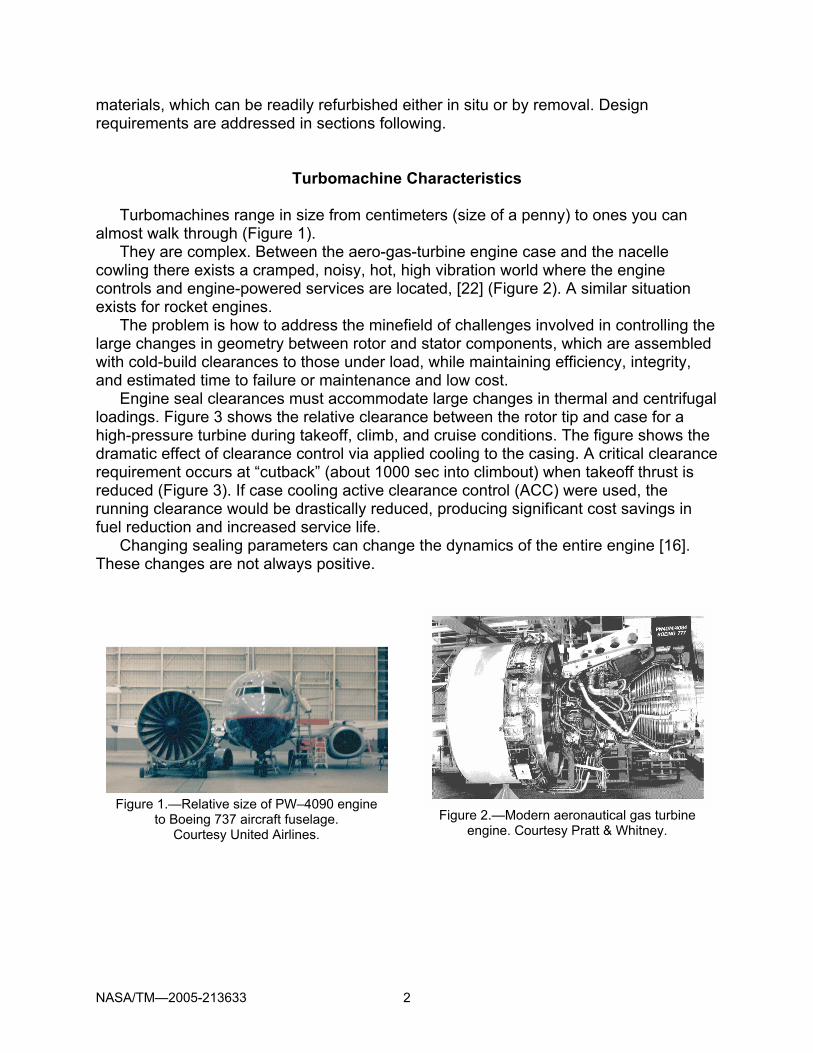
Turbomachines range in size from centimeters (size of a penny) to ones you can almost walk through (Figure 1).
They are complex. Between the aero-gas-turbine engine case and the nacelle cowling there exists a cramped, noisy, hot, high vibration world where the engine controls and engine-powered services are located, [22] (Figure 2). A similar situation exists for rocket engines.
The problem is how to address the minefield of challenges involved in controlling the large changes in geometry between rotor and stator components, which are assembled with cold-build clearances to those under load, while maintaining efficiency, integrity, and estimated time to failure or maintenance and low cost.
Engine seal clearances must accommodate large changes in thermal and centrifugal loadings. Figure 3 shows the relative clearance between the rotor tip and case for a high-pressure turbine during takeoff, climb, and cruise conditions. The figure shows the dramatic effect of clearance control via applied cooling to the casing. A critical clearance requirement occurs at “cutback” (about 1000 sec into climbout) when takeoff thrust is reduced (Figure 3). If case cooling active clearance control (ACC) were used, the running clearance would be drastically reduced, producing significant cost savings in fuel reduction and increased service life.
Changing sealing parameters can change the dynamics of the entire engine [16]. These changes are not always positive.
Figure 1.—Relative size of PW–4090 engine
to Boeing 737 aircraft fuselage. Courtesy United Airlines.
Figure 2.—Modern aeronautical gas turbine
engine. Courtesy Pratt & Whitney.

NASA/TM—2005-213633 3
Figure 3.— HPT/LPT active clearance control system (E.E. Halila, D.T. Lenahan, and
T.T. Thomas, Energy Efficient Engine High Pressure Turbine Test Hardware: Detailed Design Report, NASA CR–167955, 1982).
Seal Types, Locations, and Environments
Industrial and aeroturbomachines have many differences. The most notable are the fan and combustor. Aeroengines derive a large portion of their efficiency through the bypass fan, and have inline combustors, while industrial engines are not bound by flight requirements. Size and complexity have already been cited, and here we address some of the sealing locations along with the thermal-mechanical environments. In both types of engines, core requirements are similar but the materials restraints differ. Both static and dynamic seals such as abradables (biggest emphasis herein), labyrinth, brush, and face and mechanical seals all require special interface materials and coatings.
Over the years, advances in new base materials, notably Ni-based single crystal alloys, and coatings have allowed increased operating temperatures of turbine engine components (Figure 4).
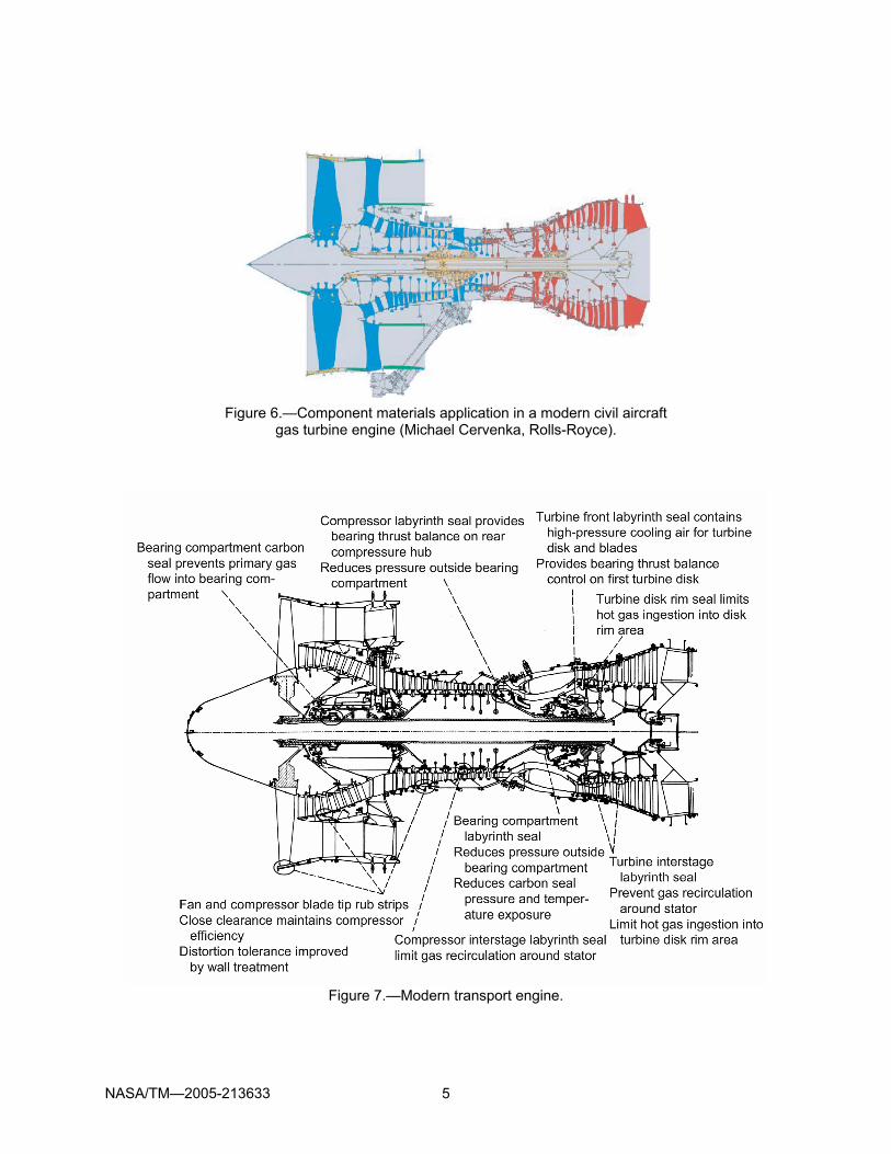
Figure 5 exemplifies the demands for materials and coatings by illustrating variations in engine pressure and temperature of the Rolls-Royce Trent gas turbine [30] (Michael Cervenka, Rolls-Royce).
Complementary to the thermal and pressure profiles, materials used in such an engine range from steel to superalloys coated with metallics and ceramics as illustrated in Figure 6. The lower temperature blades in the fan and low-pressure compressor (LPC, 400 °C (750 °F)) sections are made of titanium, or composite materials, with corrosion-resistant coatings due to their high strength and low density (blue regions). The elevated temperatures of the high-pressure compressor (HPC, 760 °C (1400 °F)), high-pressure turbine (HPT, 1150 °C (2100 °F)) and low-pressure turbine (LPT) require the use of nickel-based superalloys. In the HPT, for example, the first-stage turbine

NASA/TM—2005-213633 4
blades can see gas path temperatures around 1400 °C (2550 °F). These blades are ceramic coated and cooled to survive this extreme environment (ceramic surface at 1100 °C (2010 °F) and metal the temperature at 930 °C (1705 °F)). The orange colored components are steel including some static compressor components.
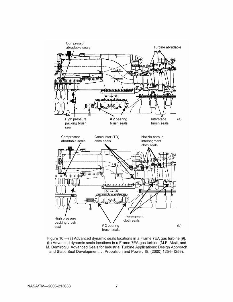
Key aeroengine sealing and thermal restraints are shown in Figure 7 such as the fan and compressor shroud seals, compressor interstage and discharge seals, combustor static seals, balance piston sealing, turbine shroud and rim-cavity sealing. Figures 8 and 9 provide a schematic of the thermal requirements and suggested types of sealing materials that can be used at these locations. Industrial engines have similar requirements and are illustrated in Figure 10, where abradable, brush, cloth sealing locations are identified. While material applications will be discussed later, abradable sealing for temperatures from the LPC to the HPT and methods of applications castings for polymer bases, brazing or diffusion bonding for honeycomb or fibermetals and thermal spray for powdered composites are cited by [9,10] (Figure 10).
Figure 4.—Component operational
temperature increases per year [28].
Figure 5.—Rolls-Royce Trent gas turbine
(Michael Cervenka, Rolls-Royce).
NASA/TM—2005-213633 5
Figure 6.—Component materials application in a modern civil aircraft
gas turbine engine (Michael Cervenka, Rolls-Royce).
Figure 7.—Modern transport engine.

NASA/TM—2005-213633 6
Figure 8.—Summary of engine operating environments and typical abradable seal materials:
1, silicone rubber, aluminum honeycomb, epoxy; 2, sprayed aluminum, sprayed nickel-graphite, silicone rubber, fibermetal; 3, Hastelloy-X fibermetal, sprayed nickel-graphite, sprayed Nichrome with additives; 4, labyrinth seals, silver braze, fibermetal, honeycomb; 5, cast superalloy (cooled),
sintered high-temperature metals, ceramics; 6, superalloy honeycomb.
Figure 9.—The intermediate and high-pressure compressor of a modern gas turbine engine
showing where the Al-Si and Ni-base abradable sealing are used and typical sea-level temperatures in the compressor.
NASA/TM—2005-213633 7
Figure 10.—(a) Advanced dynamic seals locations in a Frame 7EA gas turbine [9]. (b) Advanced dynamic seals locations in a Frame 7EA gas turbine (M.F. Aksit, and M. Demiroglu, Advanced Seals for Industrial Turbine Applications: Design Approach
and Static Seal Development. J. Propulsion and Power, 18, (2000) 1254–1259).

NASA/TM—2005-213633 8
Shroud Sealing
The sealing requirements for these flow fields are entirely different both at the blade tips and at the platform-cavity interface. The flow fields about the blade tips are complicated by vortex structures that can stall the airfoil. In the case of the compressor, the pressure gradient opposes engine flow with a propensity to unload the leading edge of the blades, which leads to compressor stall and loss of engine power. In the turbine, the pressure gradient aligns with the flow, and vortex structures shed with minimal tendency to unload the blades. Without proper sealing, the flow field can be reversed, resulting in an unstart of the engine and possible fire at the inlet. Vanes in compressor and turbine applications are also sealed differently.
Compressor interstage platform seals are of the shrouded type (Figures 14 and 15) to prevent backflow, stage pressure losses and to minimize reingested passage flow losses. Turbine stators, also of the shrouded type, prevent hot gas ingestion into the cavities that house the rotating disks and control blade and disk coolant flows. Designers need to carefully consider the differences in thermal, structural characteristics, pressure gradient differences and blade rub interfaces.
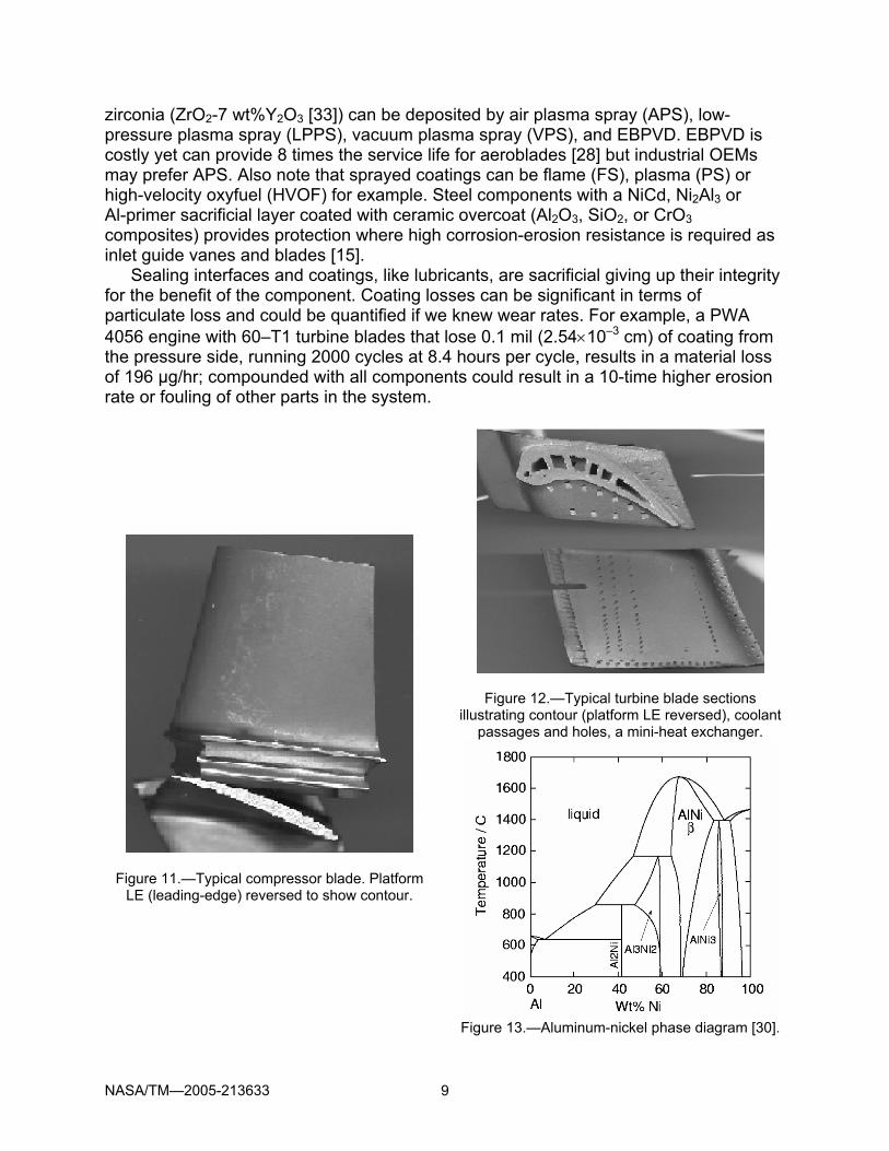
Interface flows Compressor blades are usually thin, coated, contoured titanium, steel- or nickel-based alloys [26]. They are un-shrouded and supported their entire axial length in a drum-rotor (Figure 11). Turbine nozzles, vanes, and blades are compact miniheat exchangers within the confines of a contoured airfoil (Figure 12). They are thick, superalloys, often thermal spray coated, with complex internal passages forming the heat exchange surface and film cooling necessary to endure the hostile combustion gas environment and produce power to drive the compressor and load (industrial applications) or fan (aero).
Like all heat exchangers, fouling (deposits, scale, and corrosion) become long-term enemies, robbing life and efficiency and eventual clogging. A fouled turbine blade runs hotter and small increases in temperature (16 °C (30 °F)) can half blade life. When properly applied, coatings will mitigate internal fouling, and when not, will exacerbate fouling.
Blade and vane coatings battle oxidation (reactions with hot gases), hot corrosion (reactions with salts deposited from the vapor phase), diffusion of coating elements with the substrate and thermomechanical loadings. Diffusion aluminide coatings (NiAl, Ni2Al3), usually by packed cementation (similar to chemical vapor deposition), are surface enriched, based on β-NiAl (Figure 13). Adding a 5 to 10 µm electrodeposition layer of platinum gives Pt-aluminide coatings. MCrAlY coatings are sprayed or EBPVD (electron beam physical vapor deposition), which is more costly, yet has 3 times a better life. Cleansing the base metal of sulfur seems as effective as adding the Pt or Y to the bond coat [29]; Hf may play a similar role. Silicon affords a significant improvement in cyclic oxidation resistance but lowers coating melting point to about 1140 °C (2083 °F). Additions of rhenium (Re) improve oxidation resistance (isothermal or cyclic) and thermal cycle fatigue while tantalum (Ta) increases oxidation resistance.
Thermal barrier coatings (TBC) can reduce cooling requirements by one-third or with the same cooling considerably enhance blade creep and fatigue life. Yttria-stabilized
NASA/TM—2005-213633 9
zirconia (ZrO2-7 wt%Y2O3 [33]) can be deposited by air plasma spray (APS), low-pressure plasma spray (LPPS), vacuum plasma spray (VPS), and EBPVD. EBPVD is costly yet can provide 8 times the service life for aeroblades [28] but industrial OEMs may prefer APS. Also note that sprayed coatings can be flame (FS), plasma (PS) or high-velocity oxyfuel (HVOF) for example. Steel components with a NiCd, Ni2Al3 or Al-primer sacrificial layer coated with ceramic overcoat (Al2O3, SiO2, or CrO3 composites) provides protection where high corrosion-erosion resistance is required as inlet guide vanes and blades [15].
Sealing interfaces and coatings, like lubricants, are sacrificial giving up their integrity for the benefit of the component. Coating losses can be significant in terms of particulate loss and could be quantified if we knew wear rates. For example, a PWA 4056 engine with 60–T1 turbine blades that lose 0.1 mil (2.54×10⁻³ cm) of coating from the pressure side, running 2000 cycles at 8.4 hours per cycle, results in a material loss of 196 µg/hr; compounded with all components could result in a 10-time higher erosion rate or fouling of other parts in the system.
Figure 11.—Typical compressor blade. Platform LE (leading-edge) reversed to show contour.
Figure 12.—Typical turbine blade sections illustrating contour (platform LE reversed), coolant
passages and holes, a mini-heat exchanger.
Figure 13.—Aluminum-nickel phase diagram [30].
NASA/TM—2005-213633 10
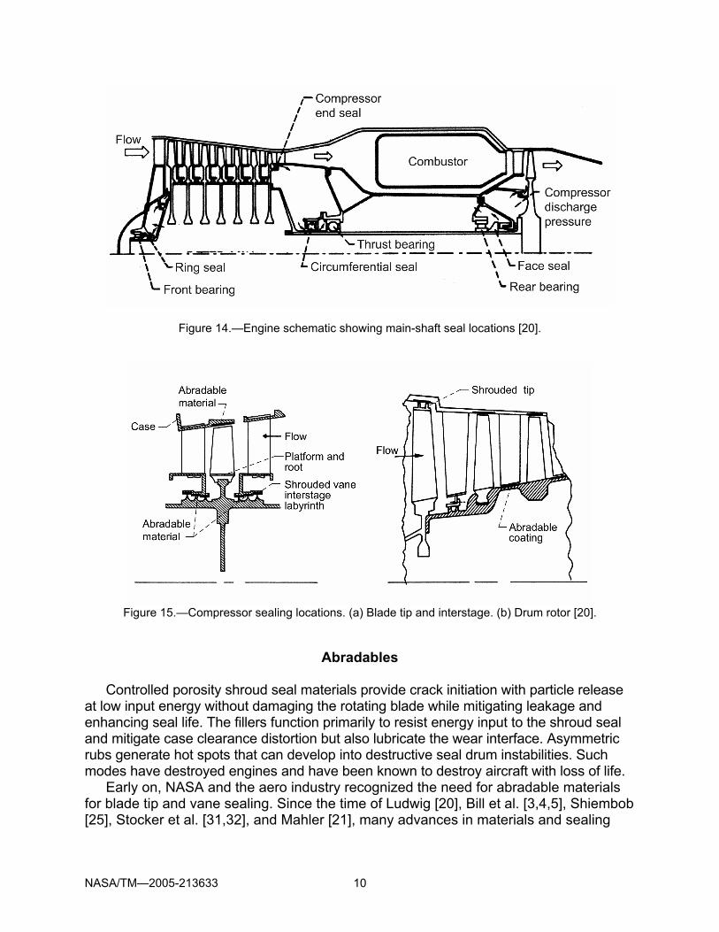
Figure 14.—Engine schematic showing main-shaft seal locations [20].
Figure 15.—Compressor sealing locations. (a) Blade tip and interstage. (b) Drum rotor [20].
Abradables
Controlled porosity shroud seal materials provide crack initiation with particle release at low input energy without damaging the rotating blade while mitigating leakage and enhancing seal life. The fillers function primarily to resist energy input to the shroud seal and mitigate case clearance distortion but also lubricate the wear interface. Asymmetric rubs generate hot spots that can develop into destructive seal drum instabilities. Such modes have destroyed engines and have been known to destroy aircraft with loss of life.
Early on, NASA and the aero industry recognized the need for abradable materials for blade tip and vane sealing. Since the time of Ludwig [20], Bill et al. [3,4,5], Shiembob [25], Stocker et al. [31,32], and Mahler [21], many advances in materials and sealing
NASA/TM—2005-213633 11
configurations have been made, yet the concepts remain much as addressed in Ludwig’s paper in 1978. Schematically, engine sealing interfaces are illustrated in Figure 14 with typical aeroengine compressor sealing locations and application of abradables shown in Figure 15. Schematics of three types of abradable materials with associated incursion types are illustrated in Figure 16 for outer airblade tip sealing interface in a compressor for example. These types of materials usually differ from the platform or inner shroud-drum rotor interface sealing of the compressor as illustrated in Figure 17.
Figure 16.—Illustration of types of compressor rub
materials for outer air sealing. (a) Abradable (sintered or sprayed porous materials). (b) Compliant (porous material). (c) Low shear strength (sprayed aluminum) [20].
Figure 17.—Inner shrouds for compressor interstage labyrinths. (a) Striated. (b) Honeycomb. (c) Porous material (abradable or compliant) [20].
Interface rub To understand abradables, we need look at the blade tip rub mechanism: the blade stays and the seal is sacrificed. The basic issues center on a material that mitigates blade wear while providing a durable interface that enhances engine efficiency. For the compressor, one needs to be aware of the large changes in thermal environment and the fact that titanium fires are not contained. Therefore rubbing must release particulate matter without engendering a fire or debris impacting downstream components. Important parameters to the tribological system are the environment, blade tip material and geometry, blade-tip incursion rate and speed, life, and reliability (mean time between overhauls). Blade rubs engender debris, which must be released to escape sliding contact wear of the blade tip and plowing of the interface, Schmidt et al. [25]; grooving can enhance stall margins, yet benefits are negated by clearance control. During a rub, material released below surface speeds of 100 m/s is primarily forward expelled chips (cutting); while above 100 m/s the expelled particles are released backward (grinding). Blade tip wear and material transfer are dominate issues. As such, the cutting tip needs to be thin (1 to 3 mm), as thicker tips trap materials and destroy the sealing interface. For these purposes, material release, porosity and structural strength can be controlled in both thermal sprayed coatings and fibermetals.
NASA/TM—2005-213633 12
Interface materials Some abradables are compacted when rubbed blade-tip-wear increases and abradable porosity decreases. Other abradables, such as honeycomb, deform at high speeds and the cell walls will rupture. Honeycomb and rotor wear is most pronounced at the brazed web where cell thickness doubles. Blade tip coatings or saw-teeth may be useful.
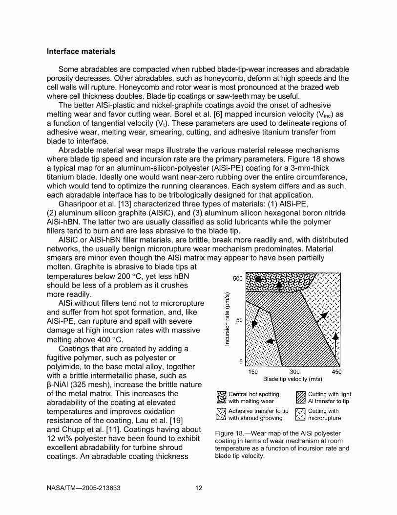
The better AlSi-plastic and nickel-graphite coatings avoid the onset of adhesive melting wear and favor cutting wear. Borel et al. [6] mapped incursion velocity (Vinc) as a function of tangential velocity (Vt). These parameters are used to delineate regions of adhesive wear, melting wear, smearing, cutting, and adhesive titanium transfer from blade to interface. Abradable material wear maps illustrate the various material release mechanisms where blade tip speed and incursion rate are the primary parameters. Figure 18 shows a typical map for an aluminum-silicon-polyester (AlSi-PE) coating for a 3-mm-thick titanium blade. Ideally one would want near-zero rubbing over the entire circumference, which would tend to optimize the running clearances. Each system differs and as such, each abradable interface has to be tribologically designed for that application.
Ghasripoor et al. [13] characterized three types of materials: (1) AlSi-PE, (2) aluminum silicon graphite (AlSiC), and (3) aluminum silicon hexagonal boron nitride AlSi-hBN. The latter two are usually classified as solid lubricants while the polymer fillers tend to burn and are less abrasive to the blade tip.
AlSiC or AlSi-hBN filler materials, are brittle, break more readily and, with distributed networks, the usually benign microrupture wear mechanism predominates. Material smears are minor even though the AlSi matrix may appear to have been partially molten. Graphite is abrasive to blade tips at temperatures below 200 °C, yet less hBN should be less of a problem as it crushes more readily.
AlSi without fillers tend not to microrupture and suffer from hot spot formation, and, like AlSi-PE, can rupture and spall with severe damage at high incursion rates with massive melting above 400 °C.
Coatings that are created by adding a fugitive polymer, such as polyester or polyimide, to the base metal alloy, together with a brittle intermetallic phase, such as β-NiAl (325 mesh), increase the brittle nature of the metal matrix. This increases the abradability of the coating at elevated temperatures and improves oxidation resistance of the coating, Lau et al. [19] and Chupp et al. [11]. Coatings having about 12 wt% polyester have been found to exhibit excellent abradability for turbine shroud coatings. An abradable coating thickness
Figure 18.—Wear map of the AISi polyester coating in terms of wear mechanism at room temperature as a function of incursion rate and blade tip velocity.
NASA/TM—2005-213633 13
in the range between 40 and 60 mils (1016 to 1524 µm) provides the best performance for turbine shrouds exposed to gas temperatures between (750 °C) 1380 °F and 1010 °C (1850 °F). The major parameters of coating life are temperature and amount of fugitive polymer. Tests included tip velocities to 375 m/s (1230 ft/s) comparable to Class E industrial machines while apparatus capability ranged from 198 to 336 m/s (650 to 1200 ft/s).
CoNiCrAlY-hBN-15 wt% polyester shows excellent abradability with nickel based superalloy and steel blades to 700 °C (1290 °F), Wei et al. [34]. For titanium blades, CoNiCrAlY-hBN-20 wt% polyester is a variant of those used for steel and Ni-superalloy materials and labeled as CoNi-20PE. The hardness is determined largely by the PE content. As-sprayed coatings with 40 to 50 vol% nonmetallic and less than 12 percent PE gave repeatable coating hardness with moderate reductions due to heat treatment. Titanium has half the modulus of nickel-based alloys and a propensity to burn in high-pressure oxygen or nitrogen. Military aircraft have been lost to titanium fires. Life and limitations As an analogy, coatings are like ones skin or gloves that protect the hands from chemical attack (e.g., oxidation), abrasion and mechanical loadings (e.g., stress, fatigue, and cutting) and thermal loads. In a similar way, overlay coatings on a cooled turbine blade mitigate tensile loadings and provide sacrificial material; TBCs are often graded to reduce thermal expansion mismatch. Component integrity and cycle life are significantly affected by its coating; coating overlay must be part of thermomechanical loading computations.
The operational thermal duty cycle for the more modern civil aircraft engines ranges from –50 °C (–57 °F) for the fan at cruise to 600 to 650 °C (1110 to 1200 °F) at the latter stage of the HPC during takeoff. AlSi-PE abradables are good to 320 °C (610 °F) and are used as shroud seals for the LPC and intermediate-pressure compressor (IPC). AlSi-C are good to 450 to 475 °C (840 to 885 °F) and are used in front of the HPC. Ni-C and AlSi-hBN and NiCrAl-bentonite (good to 815 °C (1685 °F)) are used in the HPC at the higher temperatures with Ni-C good to over 500 °C (930 °F) for short duration during takeoff. Surface corrosion is a problem overcome by the combination of AlSi and hBN, where Al is the sacrificial component.
Nava et al. [24] tested proprietary mixtures of FS and APS Ni-14Cr-8Fe-5.5BN-3.5Al (Metco 301), APS Al-8Si-20BN (Metco 320) and APS Al-17Cu-15Cr-13Fe (Praxair AL–147). A compromise between oxidation-resistance and abradability is achieved using APS AlSi-BN. In an industrial application, the abradable shroud seal life was 30 000 hours at temperatures up to 482 °C (900 °F).
Schmidt et al. [27] relates that initially compressor temperatures were limited to 350 °C (660 °F), but with α-titanium alloys, temperatures of 550 to 600 °C (1020 to 1110 °F) are possible with creep and oxidation limiting. Expectant life of compressor shroud seals are 50 000 to 100 000 hr in commercial aero and industrial gas turbines while military operations may be in the 100’s of hours. Polymer-based shroud sealing as in fan blade tip sealing, must have good casting, as these materials are difficult to machine but can be ground or spot filled. Vacuum brazing results in quality control problems, as it is difficult to determine good bonding. Thermal spraying, such as APS

NASA/TM—2005-213633 14
and FS, are most widely used for compressor shroud seals. As illustrated in Figure 8, feltmetals are responsive to higher temperatures and standardized testing needs to be addressed for use in engine design including engine cooling. NiCrAl-bentonite materials (good to 815 °C (1500 °F)) are more abrasive and can initiate titanium fires, thus they are limited to use with Ni-superalloys or steel blading. The CoNiCrAlY-hBN-20 wt% polyester is optimized for use with α-titanium blades in the 450 to 500 °C (840 to 930 °F) operating range with the potential to 600 °C (1110 °F). This material has a finer structure than that used for the steel-blade shroud material. CoNiCrAlY-hBN-20 wt% polyester could be used throughout the compressor [23], yet a designer needs a standardized comparison (feltmetal, for example) to enable sound decisions. Standardization The need for standardization of abradable seals was addressed by Chappel et al. [7,8]. Their work provides test results with a direct comparison of abradable materials in high-speed tests (to 275 m/s) at temperatures to 482 °C and low-speed tests (60 m/s) at room temperature. Fibermetal, honeycomb, and thermal spray materials are compared. The material characteristics are given in Table I.
Figure 19 shows a generic view of fibermetal material. At 15 to 30 percent porosity, the ultimate tensile strength (UTS) of sintered materials varies from 500 to 3000 psi with UTSs of 1500, 2250, and 2750 psi selected for high-speed testing. UTS values of 827, 1000, 1500, 2000, and 2600 psi were selected for low-speed testing. Hastelloy-X felt materials were selected for these tests.
The honeycomb material was Hastelloy-X with a 0.05-mm wall thickness and a 1.59 mm cell height.
Figure 19.—Scanning electron microscope
view of fibermetal [7]. Courtesy Technetics Corp.
TABLE I.—ABRADABLE MATERIALS USED BY CHAPPEL [7,8].
Fibermetal Density, %
Ultimate tensile
strength, psi
1 22 1050 2 23 2150
Honeycomb Hastelloy-X, 0.05-mm
foil, 1.59-mm cell Nickel graphite Sulzer Metco 307NS
(spray) CoNiCrAlY/hBN/PEa Sulzer Metco 2043
(spray) aHexagonal boron nitride (hBN) acts as a release agent and polyester (PE) controls porosity.

NASA/TM—2005-213633 15
The two thermal-sprayed coatings (conditions of bond coat and spray not described) were (a) nickel graphite: 0.75 Ni 0.25 C self-lubricating, suitable to 480 °C and (b) MNiCrAlY/hBN/PE-Metal (Co) alloy with hexagonal BN and polyester for porosity.
The abradability and erosion resistance represent conflicting demands on the feltmetal seal, as illustrated in Figure 20, and provides the designer with some flexibility. The high-speed wear test results for the previously cited materials are illustrated in Figure 21. Fibermetal showed essentially zero wear while ceramic and NiC produced the highest wear. For the low-speed wear results, the lower the fibermetal UTS, the lower the wear, with the other tested materials in between (apparently the ceramic was not tested at low speed). For erosion, the high-UTS fibermetal and ceramic did well with others less satisfactory.
For industrial power systems, under the conditions tested and the materials of Table I, fibermetal has the best abradability-erosion characteristics. Honeycomb materials collected on the blade tips and sprayed materials are less satisfactory abradables at the prescribed porosity. These relative ratings are illustrated in Table II.
New processes and other parameters require evaluation and standardization. For example, Coddet et al. [12] describe a process that simultaneously implements a Q-switched laser and thermal spray torch. The laser eliminates contamination films and oxide layers to enable better adhesion bond strength. Surface preparation is the key to good coatings, which can involve component masking, degreasing, and sandblasting, followed by thermal spray. With the laser precursor, only the masking is required and is
Figure 20.—Erosion and abradability as function of ultimate tensile strength [7]. Courtesy Technetics Corp.

NASA/TM—2005-213633 16
Figure 21.—Surface temperature rise with low-speed abradability test [8]. Courtesy Technetics Corp.
TABLE II.—WEAR RESISTANCE PERFORMANCE RANKINGS OF
ABRADABLE MATERIALSa Abradability Material
High speed
Low speed
Erosion
1050-psi fibermetal 1 1 3
2150-psi fibermetal 1 1 1
Hastelloy-X honeycomb 2 3 2
Nickel graphite 3 1 2
CoNiCrAlY/ hBN/PE 3 3 1 aWhere 1 = best and 3 = worst.
designed to complement existing thermal spray units as plasma guns or HVOF guns. With recent developments of femto(10–15)-sec pulsed-laser technology, computer-controlled systems can be envisioned that enable three-dimensional patterns to be etched into the substrate as well as the ceramic or metallic layers being deposited by thermal spray or other means. In some cases, proper control of the laser at the substrate can be used to prestress the surface, creating residual stresses in components where required.

NASA/TM—2005-213633 17
Guilemany et al. [14] ran standard ball on disk lubrication studies for various coatings with low coefficient of friction (µ). AlSi-PE (µ = 0.42), AlSi-C (µ = 0.1 to 0.4) and Ni-C (µ = 0.24) were studied with steel (µ = 0.65). The most common lubricants are CaF2 and graphite, C, or Ni-C with Ni-C being the best of the coatings tested with excellent resistance to wear and counterface damage.
Commercial ceramic cloth materials (e.g., Pars, Inc.) for sealing and personnel protection applications also require standardization. These materials can withstand continuous gas temperatures of 1260 °C (2300 °F) and are combined with various inserts, including Inconel wire, for greater tensile strength, with alternate forms of sleeving (e.g., rope and tape). Inroads to industrial standards have been initiated, yet more comparison tests are required before standardization becomes a reality.
The NASA work of Bill, Hendricks, Ludwig, McDonald, Steinetz et al. are the predecessors to many of the materials applications in turbomachines such as abradable and ceramic shrouds, blade coatings, rope sealing, the fiberglass cloth shaft seal, the static wire wound vehicle seals of the Leeds-Lyon conference, brush seals, and dynamics. Applications
Shroud sealing.—Glen McDonald (see Biesiadny et al. [2]) replaced bill-of-material (BOM) first-stage turbine gas path shroud seals by porosity-controlled plasma-sprayed zirconia (PSZ) ceramic-coated seals (Figure 22). The coatings were a 1-mm (0.040-in.) layer of ZrO2-8Y2O3 over a 1-mm (0.040-in.) NiCoCrAl-based bond coat onto a Haynes 25 substrate. The seals successfully ran 1001 cycles between flight idle and high power as well as steady state for a total of 57.8 hr. Characteristic “mudflat” cracking of the ceramic occurred at the blade interface, yet backside seal temperature reductions over BOM seals of 78 °C (140 °F) were measured, with gas path temperatures estimated over 1205 °C (2200 °F).
Chupp et al. [9] and [10] report abradable seals afford tighter closure of cold clearances between the rotor and case. Chupp et al. classify these in terms of location and operating temperatures (Table III).
Figure 22.—Schematic of ceramic-coated shroud seal (dimensions in millimeters and inches) [2].
TABLE III.—ABRADABLE MATERIAL CLASSIFICATION [9,10,11]
Seal Location Process AlSi + filler LPC 400 °C
(750 °F) Castings for polymer based
Ni or Co base
LPC, HPC ambient to 760 °C (1400 °F)
Brazing or diffusion bonding
YSZ and cBN or SiC
HPT 760 °C (1400 °F) to 1150 °C (2100 °F)
Thermal spray

NASA/TM—2005-213633 18
Figure 23.—Smart coatings for health monitoring and nondestructive evaluation. (a) Rene N5 superalloy with doped TBC schematic. (b) Coating after 100-hr 1200 °C test under ultraviolet light.
(c) Eu fluorescence showing crack in TBC.
Health monitoring—Crack and temperature detection.—Europium oxide Eu2O3
fluoresces red or blue when illuminated by ultraviolet light while terbium oxide Tb4O7 (terbia) produces green light. Bencic and Eldridge [1] noted that YSZ is opaque to ultraviolet excitation, but translucent to visible light; Tb3+ at 543 nm (green) and Eu3+ at 606 nm (red). Tests on Rene N5 superalloy substrate with a PtAI bond coat and graded topcoat of 50 µm [7 YSZ + 0.5 Tb], 50 µm [7 YSZ + 0.5 Eu], and 50 µm [7 YSZ] (nominal thicknesses). If the surface is flawed over 50 µm, ultraviolet excitation will reflect strong red light. With flaws >100 µm depth, the strong green light becomes visible (Figure 23). With pulsed ultraviolet, luminescence decay time can be used to assess temperature.
Summary
It is necessary for sealing interfaces and coatings, like lubricants, to be sacrificial, giving up their integrity for the benefit of the component, while not sacrificing control of leakage and coolant flows or surface stresses or engendering instabilities. Thus, for turbomachine sealing, controlling clearances becomes the major issue. Cycle efficiency,

NASA/TM—2005-213633 19
operational life and systems stability depend on effective seal design and application. No one sealing geometry or material is satisfactory for general use. Each interface must be assessed in terms of its operational requirements. Insufficient clearances limit coolant flows, cause interface rubbing, and engender turbomachine instabilities and system failures. Excessive clearances lead to losses in cycle efficiency, flow instabilities, hot gas ingestion into disk cavities. Hot gas ingestion reduces critical turbine disk life and engender bearing and materials failures. Reingestion of flow along the compressor drum interface causes unnecessary blockage and can lead to compressor stall. Yet clearance control through effective sealing becomes the most cost-effective way to enhance system performance. Coatings, films, and combined use of materials, both metals and ceramics, play a major role in maintaining interface clearances in turbomachine sealing. Herein we have turned our attention to abradable materials for shroud and platform sealing. For the aeroturbomachine, the fan shroud seals have several forms, usually polymers that can be repaired on the wing. For the compressor turbine flow path, for the LPC, ambient to 400 °C (750 °F), feltmetals and AlSi + filler can be used, but for the midrange LPC and HPC, ambient to 760 °C (1400 °F), Ni or Co base can be used (titanium blade fire protection limits); if the blades are Ni-based superalloys, NiCrAl-bentonite might be a choice. In the HPT, 760 °C (1400 °F) to 1150 °C (2100 °F), yttria-stabilized zirconia (YSZ) with controlled porosity and cBN or preferably SiC blade tip abrasive grits can be used. It all depends on how hot the engine runs, but in general, APS–TBC’s are used in the combustor, and for some engines, first vanes (nozzles) and second blades of the HPT. EB–PVD TBC’s are used on the HPT T1 or first-stage blades, some second-stage blades, and some first-stage vanes (nozzles). TBCs are not commonly used in the LPT due to lower heat flux and are less effective in decreasing component temperature. APS ceramics are also used on shroud seals (blade outer air seals) where they function as both a thermal barrier for the metallic shroud and abradable seal. Doped coatings represent a method for determining flawed TBCs and temperatures.
References [1] T.J. Bencic and J.J. Eldridge, 10th SPIE, paper no. 5770–10, 2005. [2] T.J. Biesiadny, et al., NASA TM X–86881, 1985. [3] R.C. Bill and D.W. Wisander, NASA TP–1128, 1978. [4] R.C. Bill, Wear, 59 (1980) 165–189. [5] R.C. Bill, et al., NASA TP–1835, AVRADCOM TR 80–C–19, 1981. [6] M.O. Borel, Surface and Coatings Technology, 39/40 (1989) 117–126. [7] D.E. Chappel, et al., ASME Turbo-Expo 2001, paper TE01HT02–06, 2001. [8] D.E. Chappel, et al., AIAA Paper 2001–3479, 2001. [9] R.E. Chupp, et al., AIAA Paper 2002–3795, 2002. [10] R.E. Chupp, et al., J. Prop. and Power, vol. 18, no. 6, (2002) 1260–1266. [11] R.E. Chupp, et al., GT2004–53029, ASME Turbo Expo., Vienna, Austria, 2004. [12] C. Coddet, Proc. 15th Int. Thermal Spray Conf., Nice, France, 1998,
pp.1321–1325.
NASA/TM—2005-213633 20
[13] F. Ghasripoor, et al., Proc.15th Int. Thermal Spray Conf., Nice, France, 1998 pp. 139.
[14] J.M. Guilemany, ASM Int. Materials Park, Ohio, 2001, pp. 1115–1118. [15] R.W. Haskell, U.S. Patent 5,098,797 (1992). [16] R.C. Hendricks, et al., Paper 94–GT–266 (1994). [17] R.C. Hendricks, et al., ISCORMA–2003, Gdansk-Poland (2003) pp. 40–91
(Unabridged versions NASA/TM—2004-211991/PART1, PART2, PART3). [18] R.C. Hendricks, et al., ISROMAC10–2004–037 (NASA/TM—2004-212631) (2004). [19] Y.C. Lau, et al., U.S. Patent 6,660,405 B2 (2003). [20] L.P. Ludwig, AGARD–CP–237 (AGARD–AR–123) and (NASA TM–73890 rev.)
(1978). [21] F.H. Mahler, Report PWA–4372 (Contract. No. AD–739922), Pratt-Whitney Air,
(1972). [22] M. Miller, et al., ISROMAC–7 1998 (Also NASA CP–10198, 1996). [23] P. Morrell, et al., 15th Int. Thermal Spray Conf., Nice, France, (1998) 1187–1192. [24] Y. Nava, et al., ASM Int., Materials Park, Ohio, (2001) 263–268 [25] L.T. Shiembob, (PWA–TM–5081), Pratt-Whitney Air. (NASA CR–134689) (1974). [26] P.W. Schilke, GER–3569G (2004). [27] R.K. Schmidt, et al., Thermal Spray 2000 ASM Int., Metals Park, Ohio 1087–1093. [28] U. Schulz, et al., Aerospace Science and Technology, vol. 7(1), (2003) 73–80. [29] J.L. Smialek, and B.A. Pint, NASA/TM—2000-210362, 2000. [30] T. Sourmail, Coatings for Turbine Blades, University of Cambridge,
http://www.msm.cam.ac.uk/phase-trans/2003/Superalloys/coatings/ [31] H.L. Stocker, et al., EDR–93339, Detroit Diesel Allison; NASA CR–135307 (1977). [32] H.L. Stocker, AGARD–CP–237 (AGARD–AR–123), Paper 13 (1978). [33] T.A. Taylor, ASM Int. Surface Engineering Congress, Orlando, FL, 2004.


This publication is available from the NASA Center for AeroSpace Information, 301–621–0390.
REPORT DOCUMENTATION PAGE
2. REPORT DATE
19. SECURITY CLASSIFICATION OF ABSTRACT
18. SECURITY CLASSIFICATION OF THIS PAGE
Public reporting burden for this collection of information is estimated to average 1 hour per response, including the time for reviewing instructions, searching existing data sources,gathering and maintaining the data needed, and completing and reviewing the collection of information. Send comments regarding this burden estimate or any other aspect of thiscollection of information, including suggestions for reducing this burden, to Washington Headquarters Services, Directorate for Information Operations and Reports, 1215 JeffersonDavis Highway, Suite 1204, Arlington, VA 22202-4302, and to the Office of Management and Budget, Paperwork Reduction Project (0704-0188), Washington, DC 20503.
NSN 7540-01-280-5500 Standard Form 298 (Rev. 2-89)Prescribed by ANSI Std. Z39-18298-102
Form Approved
OMB No. 0704-0188
12b. DISTRIBUTION CODE
8. PERFORMING ORGANIZATION REPORT NUMBER
5. FUNDING NUMBERS
3. REPORT TYPE AND DATES COVERED
4. TITLE AND SUBTITLE
6. AUTHOR(S)
7. PERFORMING ORGANIZATION NAME(S) AND ADDRESS(ES)
11. SUPPLEMENTARY NOTES
12a. DISTRIBUTION/AVAILABILITY STATEMENT
13. ABSTRACT (Maximum 200 words)
14. SUBJECT TERMS
17. SECURITY CLASSIFICATION OF REPORT
16. PRICE CODE
15. NUMBER OF PAGES
20. LIMITATION OF ABSTRACT
Unclassified Unclassified
Technical Memorandum
Unclassified
National Aeronautics and Space AdministrationJohn H. Glenn Research Center at Lewis FieldCleveland, Ohio 44135–3191
1. AGENCY USE ONLY (Leave blank)
10. SPONSORING/MONITORING AGENCY REPORT NUMBER
9. SPONSORING/MONITORING AGENCY NAME(S) AND ADDRESS(ES)
National Aeronautics and Space AdministrationWashington, DC 20546–0001
Available electronically at http://gltrs.grc.nasa.gov
April 2005
NASA TM—2005-213633
E–15116
Cost Center 2250000013
26
Turbomachine Interface Sealing
Robert C. Hendricks, Raymond E. Chupp, Scott B. Lattime,and Bruce M. Steinetz
Turbomachines; Seals; Materials; Plasma spray; Shroud
Unclassified -UnlimitedSubject Categories: 07, 26, 27, 37, and 45
Prepared for the International Conference on Metallurgical Coatings and Thin Films sponsored by the AVS Science &Technology, San Diego, California, May 2–6, 2005. Robert C. Hendricks and Bruce M. Steinetz, NASA Glenn ResearchCenter; Raymond E. Chupp, General-Electric Global Research Center, Niskayuna, New York 12309; and Scott B.Lattime, University of Akron, 302 Buchtel Mall, Akron, Ohio 44325 and NASA Resident Research Associate at GlennResearch Center. Responsible person, Robert C. Hendricks, organization code R, 216–977–7507.
Sealing interfaces and coatings, like lubricants, are sacrificial, giving up their integrity for the benefit of the component.Clearance control is a major issue in power systems turbomachine design and operational life. Sealing becomes themost cost-effective way to enhance system performance. Coatings, films, and combined use of both metals andceramics play a major role in maintaining interface clearances in turbomachine sealing and component life. Thispaper focuses on conventional and innovative materials and design practices for sealing interfaces.