Embed Size (px)
Citation preview
TurboChill WaterCooled Chiller
Technical Manual
TurboChill Water Cooled Chillers
2 Chiller Technical Manual 7267818 V1.0.0_10_2011
Warranty, Commissioning & MaintenanceAs standard, Airedale guarantees all non consumable parts only for a period of 12 months, variations tailored to suit product and application are also available; please contact Airedale for full terms and details.
To further protect your investment in Airedale products, Airedale can provide full commissioning services, comprehensive maintenance packages and service cover 24 hours a day, 365 days a year (UK mainland). For a free quotation contact Airedale or your local Sales Engineer.
All Airedale products are designed in accordance with EU Directives regarding prevention of build up of water, associated with the risk of contaminants such as Legionella.
For effective prevention of such risk it is necessary that the equipment is maintained in accordance with Airedale recommendations.
CAUTION
Warranty cover is not a substitute for maintenance. Warranty cover is conditional to maintenance being carried out in accordance with the recommendations provided during the warranty period. Failure to have the maintenance procedures carried out will invalidate the warranty and any liabilities by Airedale International Air Conditioning Ltd.
SparesA spares list for 1, 3 and 5 years will be supplied with every unit and is also available from our Spares department on request.
TrainingAs well as our comprehensive range of products, Airedale offers a modular range of Refrigeration and Air Conditioning Training courses, for further information please contact Airedale.
Customer ServicesFor further assistance, please e-mail: [email protected] or telephone:
UK Sales Enquiries + 44 (0) 113 239 1000 [email protected] Enquiries + 44 (0) 113 239 1000 [email protected] Hot Line + 44 (0) 113 238 7878 [email protected] Airedale Service + 44 (0) 113 239 1000 [email protected] Support + 44 (0) 113 239 1000 [email protected] Enquiries + 44 (0) 113 239 1000 [email protected]
For information, visit us at our Web Site: www.airedale.com
AIAC Ltd endeavours to ensure that the information in this document is correct and fairly stated, but none of the statements are to be relied upon as a statement or representation of fact. AIAC Ltd does not accept liability for any error or omission, or for any reliance placed on the information contained in this document.The development of Airedale products and services is continuous and the information in this document may not be up to date. It is important to check the current position with AIAC Ltd at the address stated. This document is not part of a contract or licence unless expressly agreed.No part of this document may be reproduced or transmitted in any form or by any means, electronic or mechanical, including photocopying, recording, or information storage and retrieval systems, for any purpose other than the purchaser’s personal use, without the express written permission of AIAC Ltd.
© 2011 Airedale International Air Conditioning Limited. All rights reserved. Printed in the UK.
Turbochill Water CooledChillers
3Chiller Technical Manual 7267818 V1.0.0_10_2011
Warranty All AIAC products or parts (non consumable) supplied for installation within the UK mainland and commissioned by an AIAC engineer, carry a full Parts & Labour warranty for a period of 12 months from the date of commissioning or 18 months from the date of despatch, whichever is the sooner.Parts or Equipment supplied by AIAC for installation within the UK or for Export that are properly commissioned in accordance with AIAC standards and specifi cation, not commissioned by an AIAC engineer; carry a 12 month warranty on non consumable Parts only from the date of commissioning or 18 months from the date of despatch, whichever is the sooner.Parts or equipment installed or commissioned not to acceptable AIAC standards or specifi cation invalidate all warranty.
Warranty is only valid in the event thatIn the period between delivery and commissioning the equipment: is properly protected & serviced as per the AIAC installation & maintenance manual provided where applicable the glycol content is maintained to the correct level.In the event of a problem being reported and once warranty is confi rmed as valid under the given installation and operating conditions, the Company will provide the appropriate warranty coverage (as detailed above) attributable to the rectifi cation of any affected Airedale equipment supplied (excluding costs for any specialist access or lifting equipment that must be ordered by the customer).Any spare part supplied by Airedale under warranty shall be warranted for the unexpired period of the warranty or 3 months from delivery, whichever period is the longer.To be read in conjunction with the Airedale Conditions of Sale - Warranty and Warranty Procedure, available upon request.
ProcedureWhen a component part fails, a replacement part should be obtained through our Spares department. If the part is considered to be under warranty, the following details are required to process this requirement.• Full description of part required, including Airedale’s part number, if know.• The original equipment serial number• An appropriate purchase order number A spares order will be raised under our warranty system and the replacement part will be despatched, usually within 24 hours should they be in stock. When replaced, the faulty part must be returned to Airedale with a suitably completed and securely attached “Faulty Component Return” (FCR) tag. FCR tags are available from Airedale and supplied with each Warranty order. On receipt of the faulty part, suitably tagged, Airedale will pass to its Warranty department, where it will be fully inspected and tested in order to identify the reason for failure, identifying at the same time whether warranty is justifi ed or not.On completion of the investigation of the returned part, a full “Report on Goods Returned” will be issued. On occasion the release of this complete report may be delayed as component manufacturers become involved in the investigation. When warranty is allowed, a credit against the Warranty invoice will be raised. Should warranty be refused the Warranty invoice becomes payable on normal terms.Exclusions Warranty may be refused for the following reasons:• Misapplication of product or component• Incorrect site installation• Incomplete commissioning documentation• Inadequate site installation• Inadequate site maintenance• Damage caused by mishandling• Replaced part being returned damaged without explanation• Unnecessary delays incurred in return of defective componentReturns analysis All faulty components returned under warranty are analysed on a monthly basis as a means of verifying component and product reliability as well as supplier performance. It is important that all component failures are reported correctly.
TurboChill Water Cooled Chillers
4 Chiller Technical Manual 7267818 V1.0.0_10_2011
Health and SafetyIMPORTANT The information contained in this manual is critical to the correct operation and maintenance of the unit and should be read by all persons responsible for the installation, commissioning and maintenance of this Airedale unit.
Safety The equipment has been designed and manufactured to meet international safety standards but, like any mechanical/electrical equipment, care must be taken if you are to obtain the best results.
CAUTIONInstallation, service and maintenance of Airedale equipment should only be carried out by technically trained competent personnel.
CAUTIONWhen working with any air conditioning units ensure that the electrical isolator is switched off prior to servicing or repair work and that there is no power to any part of the equipment.
Also ensure that there are no other power feeds to the unit such as fi re alarm circuits, BMS circuits etc.
Electrical installation commissioning and maintenance work on this equipment should be undertaken by competent and trained personnel in accordance with local relevant standards and codes of practice.
The refrigerant used in this range of products is classifi ed under the COSHH regulations as an irritant, with set Workplace Exposure Levels (WEL) for consideration if this plant is installed in confi ned or poorly ventilated areas.
A full hazard data sheet in accordance with COSHH regulations is available should this be required.
Protective Personal EquipmentAiredale recommends that personal protective equipment is used whilst installing, maintaining and commissioning equipment.
Refrigerant WarningThe Airedale Turbochill Water cooled unit uses R134a refrigerant which requires careful attention to proper storage and handling procedures.
Use on manifold gauge sets designed for use with R134a refrigerant. Use only refrigerant recovery units and cylinders designed for high pressure refrigerants.
R134a must only be charged in the liquid state to ensure correct blend makeup.
The refrigerant must be stored in a clean, dry area away from sunlight. The refrigerant must never be stored above 50°C.
Manual HandlingSome operations when servicing or maintaining the unit may require additional assistance with regard to manual handling. This requirement is down to the discretion of the engineer. Remember do not perform a lift that exceeds your ability.
Turbochill Water CooledChillers
5Chiller Technical Manual 7267818 V1.0.0_10_2011
Environmental Considerations Freeze ProtectionAiredale recommends the following actions to help protect the unit during low temperature operation. This also includes the units subject to low ambient temperatures.
Units with supply water temperatures below +5°CGlycol is recommended when a supply water temperature of +5°C or below is required or when static water can be exposed to freezing temperatures.
Units subject to ambient temperatures lower than 0°CGlycol of an appropriate concentration (1) is used within the system to ensure adequate protection. Please ensure that the concentration is capable of protection at least 3°C lower than ambient.
Water / glycol solution is constantly circulated through all waterside pipework and coils to avoid static water from freezing.
Ensure that pumps are started and running even during shut down periods, when the ambient is within 3°C of the solution freeze point (1) (i.e. if the solution freezes at 0°C, the pump must be operating at 3°C ambient).
Additional trace heating is provided for interconnecting pipework.
(1) Referrer to your glycol supplier for details
Environmental PolicyIt is our policy to: • Take a proactive approach to resolve environmental issues and ensure compliance with regulatory requirements. • Train personnel in sound environmental practices. • Pursue opportunities to conserve resources, prevent pollution and eliminate waste. • Manufacture products in a responsible manner with minimum impact on the environment. • Reduce our use of chemicals and minimise their release to the environment. • Measure, control and verify environmental performance through internal and external audits. • Continually improve our environmental performance.
CE Directive Airedale certify that the equipment detailed in this manual conforms with the following EC Directives: Electromagnetic Compatibility Directive (EMC) 2004/108/EC Low Voltage Directive (LVD) 2006/95/EC Machinery Directive (MD) 89/392/EEC version 2006/42/EC Pressure Equipment Directive (PED) 97/23/EC To comply with these directives appropriate national & harmonised standards have been applied. These are listed on the Declaration of Conformity, supplied with each product.
TurboChill Water Cooled Chillers
6 Chiller Technical Manual 7267818 V1.0.0_10_2011
Table of ContentsWarranty, Commissioning & Maintenance 2
Spares 2Training 2Customer Services 2
Health and Safety 4Protective Personal Equipment 4Refrigerant Warning 4Manual Handling 4
Environmental Considerations 5Freeze Protection 5Environmental Policy 5
General Description 7Nomenclature 7Introduction 7Refrigerants 7Standard Features – General 10Construction 10Water Connections 10Condenser 10Controls 13Performance Data 14Mechanical Data 15Electrical Data 16Waterside Pressure Drops 17
Technical Data 19Ethylene Glycol 19Propylene Glycol 20Minimum System Water Volume Calculations 21
Installation Data 22Dimensional Data 22Unit Lifting 30Service & Maintenance Clearances 31Anti Vibration Mounting (Optional) 32Standard Recommended Pipework Installation 33Interconnecting Wiring 37
Controls 38Commissioning 41
Pre Commissioning Checklist 41Commissioning Procedure 42Controls 43
Maintenance 45Owner responsibility 45
Maintenance Advice 47Storage Recommendations 48
Turbochill Water CooledChillers
7Chiller Technical Manual 7267818 V1.0.0_10_2011
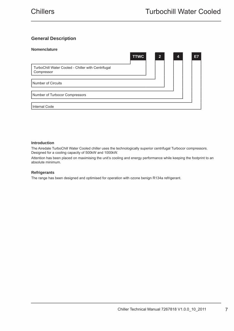
IntroductionThe Airedale TurboChill Water Cooled chiller uses the technologically superior centrifugal Turbocor compressors. Designed for a cooling capacity of 500kW and 1000kW.Attention has been placed on maximising the unit’s cooling and energy performance while keeping the footprint to an absolute minimum.
RefrigerantsThe range has been designed and optimised for operation with ozone benign R134a refrigerant.
General Description
Nomenclature
TTWC 2 4 E7
TurboChill Water Cooled - Chiller with Centrifugal Compressor
Number of Circuits
Number of Turbocor Compressors
Internal Code
TurboChill Water Cooled Chillers
8 Chiller Technical Manual 7267818 V1.0.0_10_2011
Compressor
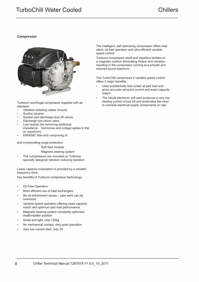
Turbocor centrifugal compressor supplied with as standard:• Vibration isolating rubber mounts • Suction strainer • Suction and discharge shut off valves • Discharge non-return valve • Line reactor (for removing additional
impedance harmonics and voltage spikes in the ac waveform)
• EMI/EMC fi lter and comprising of:
and incorporating surge protection Soft start module Magnetic bearing system • The compressors are mounted on Turbocor
specially designed vibration reducing isolation. Linear capacity modulation is provided by a variable frequency drive. Key benefi ts of Turbocor compressor technology: • Oil Free Operation• More effi cient use of heat exchangers• No oil entrainment issues – pipe work can be
oversized• Variable speed operation offering exact capacity
match and optimum part load performance • Magnetic bearing system constantly optimises
shaft/impeller position • Small and light, only 120kg• No mechanical contact, very quiet operation• Very low current start, only 2A
The intelligent, self optimising compressor offers near silent, oil free operation and ultra effi cient variable speed control. Turbocor compressor shaft and impellers levitate on a magnetic cushion eliminating friction and vibration resulting in the compressor running at a smooth and reduced sound spectrum.
The TurboChill compressor’s variable speed control offers 2 major benefi ts: • Uses substantially less power at part load and
gives accurate set-point control and exact capacity match
• The inbuilt electronic soft start produces a very low starting current of just 2A and eradicates the need to oversize electrical supply components on site.
Turbochill Water CooledChillers
9Chiller Technical Manual 7267818 V1.0.0_10_2011
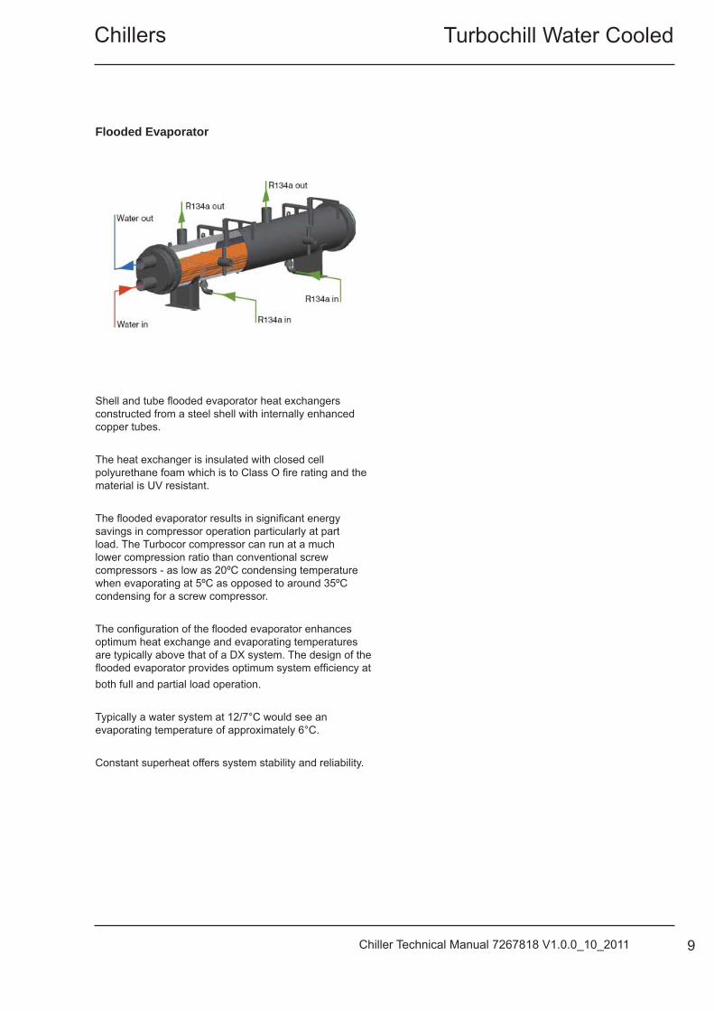
Flooded Evaporator
Shell and tube fl ooded evaporator heat exchangers constructed from a steel shell with internally enhanced copper tubes.
The heat exchanger is insulated with closed cell polyurethane foam which is to Class O fi re rating and the material is UV resistant.
The fl ooded evaporator results in signifi cant energy savings in compressor operation particularly at part load. The Turbocor compressor can run at a much lower compression ratio than conventional screw compressors - as low as 20ºC condensing temperature when evaporating at 5ºC as opposed to around 35ºC condensing for a screw compressor.
The confi guration of the fl ooded evaporator enhances optimum heat exchange and evaporating temperatures are typically above that of a DX system. The design of the fl ooded evaporator provides optimum system effi ciency atboth full and partial load operation.
Typically a water system at 12/7°C would see an evaporating temperature of approximately 6°C.
Constant superheat offers system stability and reliability.
TurboChill Water Cooled Chillers
10 Chiller Technical Manual 7267818 V1.0.0_10_2011
Standard Features – GeneralFeatures The High Effi ciency Quiet TurboChill Chiller is supplied complete with:• Turbocor Oil Free Compressors• Microprocessor Control• Shell & Tube Flooded Evaporator• Shell and tube condenser• Dual Independent Refrigeration Circuits• Acoustically Lined compressor enclosures• Liquid Level Transmitters and Liquid Level Control
Valves • Intelligent Head Pressure Control• Maintainable Dual Pressure Relief Valves• Grooved water connections & counter pipe assembly• Differential Pressure sensor across the evaporator of-
fers the same protection as a water fl ow switch.
ConstructionThe base is fabricated from galvanised steel to ensure a rigid, durable, weatherproof construction.Unit panels are manufactured from galvanised sheet steel coated with epoxy baked powder paint to provide a durable and weatherproof fi nish. Standard unit colour is Light Grey (RAL 7035).Compressors, Evaporator and Condenser are mounted on a rigid galvanised heavy-duty sub frame. Fully weatherproofed electrical panels are situated at one side of the unit.
Water ConnectionsWater inlet and outlet connections are of a grooved and clamped type construction. The unit is supplied with a counter pipe and coupling assembly for quick installation.Optional fl anged connections available on request, please consult Airedale.Water inlet and outlet are located at the end of the unit.
CondenserShell and tube condenser will allow optimum heat transfer between media.
Water inlet and outlet connections are grooved type pipe and coupling assembly (counter-pipes and clamps supplied).
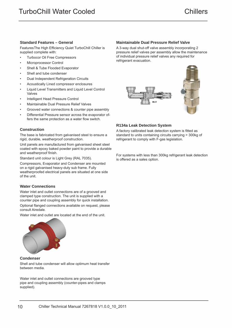
Maintainable Dual Pressure Relief Valve A 3-way dual shut-off valve assembly incorporating 2 pressure relief valves per assembly allow the maintenance of individual pressure relief valves any required for refrigerant evacuation.
R134a Leak Detection SystemA factory calibrated leak detection system is fi tted as standard to units containing circuits carrying > 300kg of refrigerant to comply with F-gas legislation.
For systems with less than 300kg refrigerant leak detection is offered as a sales option.
Turbochill Water CooledChillers
11Chiller Technical Manual 7267818 V1.0.0_10_2011
Refrigeration
Each refrigeration circuit is supplied with the following:• Full operating charge of R134a• Liquid injection cooling circuit fi tted to each compressor as standard with sight glass, fi lter drier and ball valve• Liquid level transmitters and control valves• Discharge line shut off valves• Compressor suction line shut off valves• Liquid line shut off valves• Large capacity fi lter driers with replaceable cores• Evaporator and Liquid line sight glasses• Low pressure switch with Auto reset• 2 High pressure switches with manual reset per compressor• Liquid pressure transducers• Discharge check (non return) valves
Water / Glycol Each water glycol circuit is supplied with the following:• Differential Pressure sensor across the evaporator offers the same protection as fl ow switches• Strategically placed automatic air vents• Strategically placed drain valves
TurboChill Water Cooled Chillers
12 Chiller Technical Manual 7267818 V1.0.0_10_2011
Electrical A weatherproof electrical power and controls panel is situated at the front of the unit and contains:
• Individual mains power isolator for each compressor• Separate electrical MCB isolation for fan mains• Dedicated bus-bar chamber for connection of incoming 3-phase and earth mains power supply• Emergency Stop fi tted to compressor mains compartment door• Separate, fully accessible, controls compartment, allowing adjustment of control set points whilst the unit is
operational• Circuit breakers for protection of all major unit components• Phase rotation relay incorporating phase loss protection (not fi tted if energy manager selected)The electrical power and control panel is wired to the latest European standards and codes of practice.Mains supply is 3 phase, a neutral is not required Separate 230V permanent supply is required for the controls and safety features. Electrical terminals for external evaporator pipework trace heating (230V/500W) are provided.
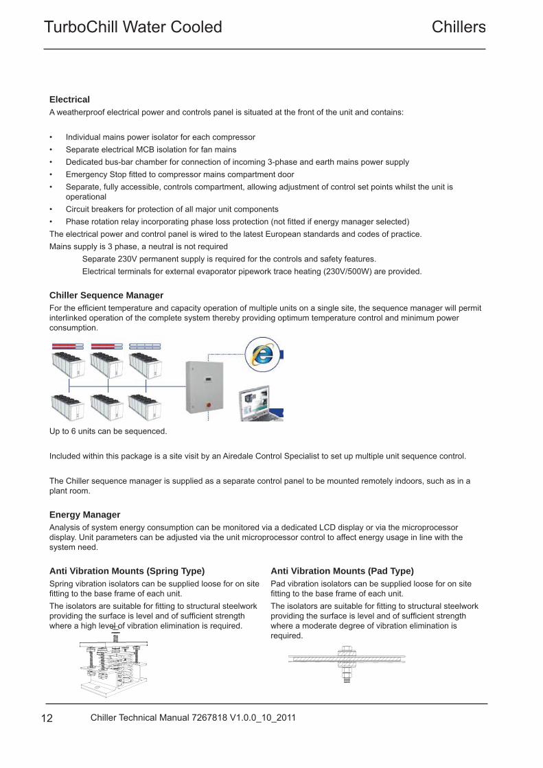
Chiller Sequence ManagerFor the effi cient temperature and capacity operation of multiple units on a single site, the sequence manager will permit interlinked operation of the complete system thereby providing optimum temperature control and minimum power consumption.
Up to 6 units can be sequenced.
Included within this package is a site visit by an Airedale Control Specialist to set up multiple unit sequence control.
The Chiller sequence manager is supplied as a separate control panel to be mounted remotely indoors, such as in a plant room.
Energy ManagerAnalysis of system energy consumption can be monitored via a dedicated LCD display or via the microprocessor display. Unit parameters can be adjusted via the unit microprocessor control to affect energy usage in line with the system need.
Anti Vibration Mounts (Spring Type)Spring vibration isolators can be supplied loose for on site fi tting to the base frame of each unit.The isolators are suitable for fi tting to structural steelwork providing the surface is level and of suffi cient strength where a high level of vibration elimination is required.
Anti Vibration Mounts (Pad Type)Pad vibration isolators can be supplied loose for on site fi tting to the base frame of each unit.The isolators are suitable for fi tting to structural steelwork providing the surface is level and of suffi cient strength where a moderate degree of vibration elimination is required.
Turbochill Water CooledChillers
13Chiller Technical Manual 7267818 V1.0.0_10_2011
Controls
As standard, the microprocessor controller can provide an infi nite capacity control between 7.5% and 100%, depending on the component selection.Optionally, the controller is designed to provide capabilities for;• Building Management Systems (BMS)• Sequencing (Master/Slave and Run/Standby)to meet all your system requirements, please specify at time of enquiry.The microprocessor controller offers powerful analogue and digital control to meet a wide range of monitoring and control features including a real time clock and Industry standard communication port and network connections.
The controller’s inbuilt display is used for viewing the unit operating status and making adjustments to control parameters by allowing the operator access to a series of display pages.
Also featured are a visual alarm and the facility to adjust and display control settings by local operator for information and control.
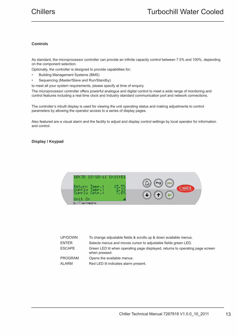
Display / Keypad
UP/DOWN To change adjustable fi elds & scrolls up & down available menus. ENTER Selects menus and moves cursor to adjustable fi elds green LED. ESCAPE Green LED lit when operating page displayed, returns to operating page screen when pressed. PROGRAM Opens the available menus. ALARM Red LED lit indicates alarm present.
TurboChill Water Cooled Chillers
14 Chiller Technical Manual 7267818 V1.0.0_10_2011
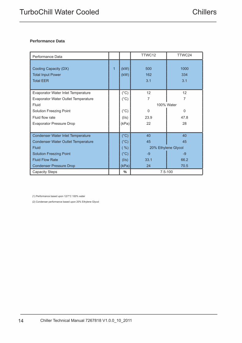
Performance Data
Performance Data TTWC12 TTWC24
Cooling Capacity (DX) 1 (kW) 500 1000Total Input Power (kW) 162 334Total EER 3.1 3.1
Evaporator Water Inlet Temperature (°C) 12 12Evaporator Water Outlet Temperature (°C) 7 7Fluid 100% WaterSolution Freezing Point (°C) 0 0
Fluid fl ow rate (l/s) 23.9 47.8Evaporator Pressure Drop (kPa) 22 28
Condenser Water Inlet Temperature (°C) 40 40Condenser Water Outlet Temperature (°C) 45 45Fluid ( %) 20% Ethylene GlycolSolution Freezing Point (°C) -9 -9Fluid Flow Rate (l/s) 33.1 66.2Condenser Pressure Drop (kPa) 24 70.5Capacity Steps % 7.5-100
(1) Performance based upon 12/7°C 100% water
(2) Condenser performance based upon 20% Ethylene Glycol
Turbochill Water CooledChillers
15Chiller Technical Manual 7267818 V1.0.0_10_2011
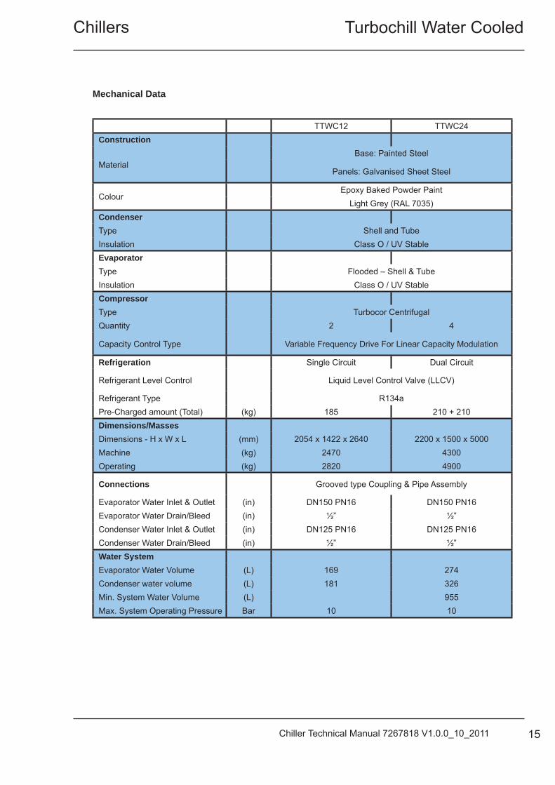
TTWC12 TTWC24Construction
MaterialBase: Painted Steel
Panels: Galvanised Sheet Steel
ColourEpoxy Baked Powder Paint
Light Grey (RAL 7035)CondenserType Shell and TubeInsulation Class O / UV StableEvaporatorType Flooded – Shell & TubeInsulation Class O / UV StableCompressorType Turbocor CentrifugalQuantity 2 4
Capacity Control Type Variable Frequency Drive For Linear Capacity Modulation
Refrigeration Single Circuit Dual Circuit
Refrigerant Level Control Liquid Level Control Valve (LLCV)
Refrigerant Type R134aPre-Charged amount (Total) (kg) 185 210 + 210Dimensions/MassesDimensions - H x W x L (mm) 2054 x 1422 x 2640 2200 x 1500 x 5000Machine (kg) 2470 4300Operating (kg) 2820 4900
Connections Grooved type Coupling & Pipe Assembly
Evaporator Water Inlet & Outlet (in) DN150 PN16 DN150 PN16Evaporator Water Drain/Bleed (in) ½” ½”Condenser Water Inlet & Outlet (in) DN125 PN16 DN125 PN16Condenser Water Drain/Bleed (in) ½” ½”Water SystemEvaporator Water Volume (L) 169 274Condenser water volume (L) 181 326Min. System Water Volume (L) 955Max. System Operating Pressure Bar 10 10
Mechanical Data
TurboChill Water Cooled Chillers
16 Chiller Technical Manual 7267818 V1.0.0_10_2011
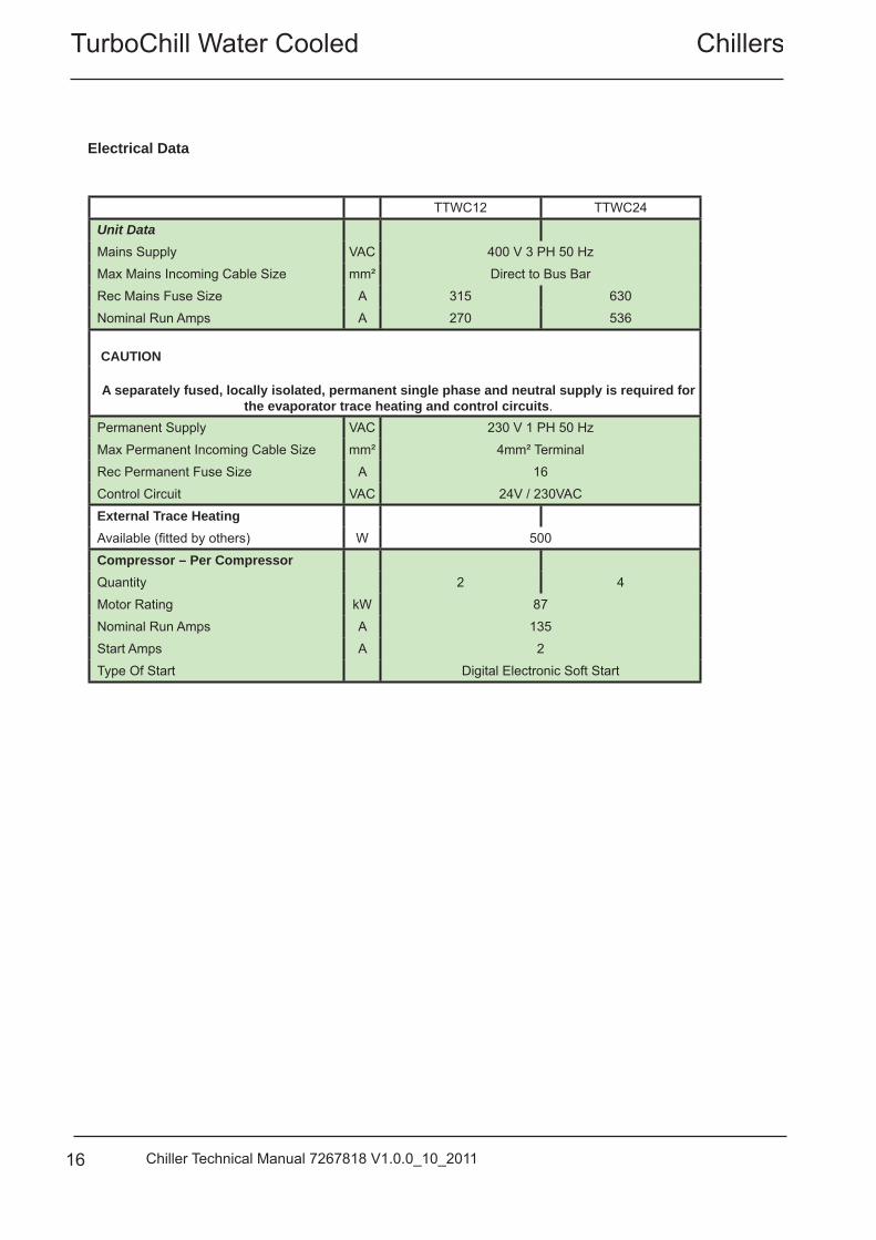
Electrical Data
TTWC12 TTWC24
Unit DataMains Supply VAC 400 V 3 PH 50 Hz
Max Mains Incoming Cable Size mm² Direct to Bus Bar
Rec Mains Fuse Size A 315 630
Nominal Run Amps A 270 536
CAUTION
A separately fused, locally isolated, permanent single phase and neutral supply is required for the evaporator trace heating and control circuits.
Permanent Supply VAC 230 V 1 PH 50 Hz
Max Permanent Incoming Cable Size mm² 4mm² Terminal
Rec Permanent Fuse Size A 16
Control Circuit VAC 24V / 230VAC
External Trace HeatingAvailable (fi tted by others) W 500
Compressor – Per CompressorQuantity 2 4
Motor Rating kW 87
Nominal Run Amps A 135
Start Amps A 2
Type Of Start Digital Electronic Soft Start
Turbochill Water CooledChillers
17Chiller Technical Manual 7267818 V1.0.0_10_2011
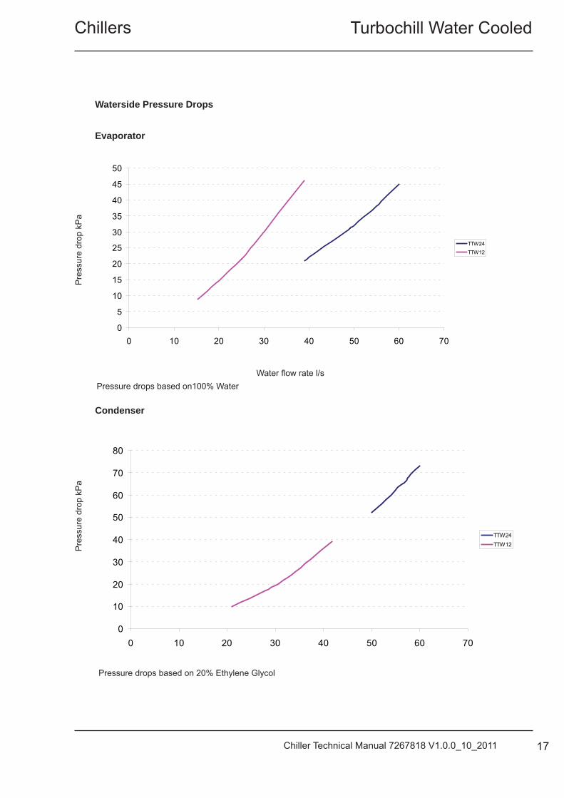
Waterside Pressure Drops
Evaporator
Condenser
Pressure drops based on 20% Ethylene Glycol
Water fl ow rate l/s
Water fl ow rate l/s
Pre
ssur
e dr
op k
Pa
Pre
ssur
e dr
op k
Pa
0
10
20
30
40
50
60
70
80
0 10 20 30 40 50 60 70
TTW24TTW12
0
5
10
15
20
25
30
35
40
45
50
0 10 20 30 40 50 60 70
TTW24TTW12
Pressure drops based on100% Water

TurboChill Water Cooled Chillers
18 Chiller Technical Manual 7267818 V1.0.0_10_2011
Glycol Data For a given percentage of glycol in the system there are correction factors that need to be applied, the following tables can be used as a guide.
CAUTION The source data must be at 20% Glycol for the correction factors to be valid.
This data is for a guide only. Please contact Airedale for accurate fi gures. Where: Output = (kW) Output (kW) Compressor Input = (kW) Input (kW), (-) Minus TFP TFP (Total Fan Power) = (kW) Quantity of Fans to unit x Fan Motor Size. Water Flow = (l/s) ALWAYS USE 20% Glycol Specifi c heat Capacity of 3.9. ΔT = (°C) Difference of Entering Water and Leaving Water temperature Ethylene Glycol Nominal Correction Factors
Ethylene Glycol
Glycol in System / Freezing Point ºC 20% / -9°C 30% / -15°C 40% / -23°CCooling Duty x by 1 0.98 0.96Input Power 1 0.98 0.97Water Flow 1 1.02 1.05Pressure Drop 1 1.15 1.31
Propylene Glycol
Glycol in System / Freezing Point ºC 20% / -6°C 30% / -12°C 40% / -20°CCooling Duty x by 1 0.96 0.93Input Power 1 0.98 0.97Water Flow 1 0.98 0.98Pressure Drop 1 1.13 1.25 Example TTWC24E7 operating at 6/12°C evaporator, 51/45°C condenser water, 30% Ethylene Glycol
Cooling kW (1000) x 0.98 30% Ethylene Glycol = 980 kW Input kW (319) x 0.98 312.6 kW Flow l/s (39.8)(calculated: ) x 1.02 40.6 l/s Pressure Drop kPa (21.5) x 1.15 24.7 kPa
Turbochill Water CooledChillers
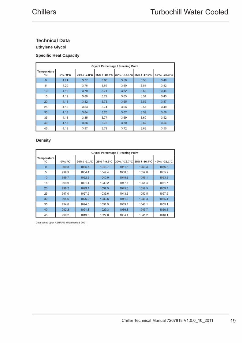
19Chiller Technical Manual 7267818 V1.0.0_10_2011
Glycol Percentage / Freezing Point
Temperature °C 0% / 0°C 20% / -7.8°C 25% / -10.7°C 30% / -14.1°C 35% / -17.9°C 40% / -22.3°C
0 4.21 3.77 3.68 3.59 3.50 3.40
5 4.20 3.78 3.69 3.60 3.51 3.42
10 4.19 3.79 3.71 3.62 3.53 3.44
15 4.19 3.80 3.72 3.63 3.54 3.45
20 4.18 3.82 3.73 3.65 3.56 3.47
25 4.18 3.83 3.74 3.66 3.57 3.49
30 4.18 3.84 3.76 3.67 3.59 3.50
35 4.18 3.85 3.77 3.69 3.60 3.52
40 4.18 3.86 3.78 3.70 3.62 3.54
45 4.18 3.87 3.79 3.72 3.63 3.55
Density
Glycol Percentage / Freezing Point
Temperature °C 0% / °C 20% / -7.1°C 25% / -9.6°C 30% / -12.7°C 35% / -16.4°C 40% / -21.1°C
0 999.8 1035.7 1043.7 1051.8 1059.3 1066.8
5 999.9 1034.4 1042.4 1050.3 1057.8 1065.2
10 999.7 1032.9 1040.9 1048.8 1056.1 1063.5
15 999.0 1031.4 1039.2 1047.1 1054.4 1061.7
20 998.2 1029.7 1037.5 1045.3 1052.5 1059.7
25 997.0 1027.9 1035.6 1043.3 1050.5 1057.6
30 995.6 1026.0 1033.6 1041.3 1048.3 1055.4
35 994.0 1024.0 1031.5 1039.1 1046.1 1053.1
40 992.2 1021.8 1029.3 1036.8 1043.7 1050.6
45 990.2 1019.6 1027.0 1034.4 1041.2 1048.1
Ethylene Glycol
Data based upon ASHRAE fundamentals 2001
Technical Data
Specifi c Heat Capacity
TurboChill Water Cooled Chillers
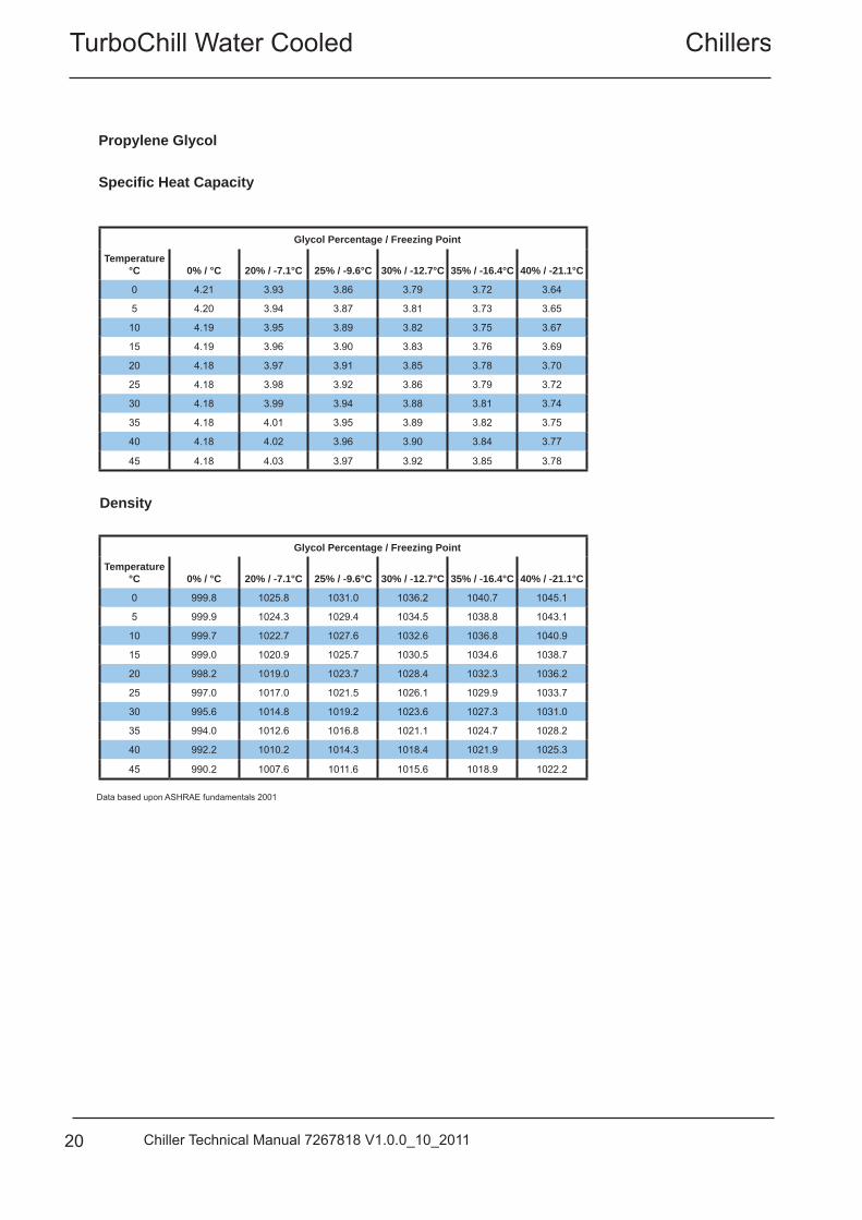
20 Chiller Technical Manual 7267818 V1.0.0_10_2011
Glycol Percentage / Freezing Point
Temperature °C 0% / °C 20% / -7.1°C 25% / -9.6°C 30% / -12.7°C 35% / -16.4°C 40% / -21.1°C
0 4.21 3.93 3.86 3.79 3.72 3.64
5 4.20 3.94 3.87 3.81 3.73 3.65
10 4.19 3.95 3.89 3.82 3.75 3.67
15 4.19 3.96 3.90 3.83 3.76 3.69
20 4.18 3.97 3.91 3.85 3.78 3.70
25 4.18 3.98 3.92 3.86 3.79 3.72
30 4.18 3.99 3.94 3.88 3.81 3.74
35 4.18 4.01 3.95 3.89 3.82 3.75
40 4.18 4.02 3.96 3.90 3.84 3.77
45 4.18 4.03 3.97 3.92 3.85 3.78
Density
Glycol Percentage / Freezing Point
Temperature °C 0% / °C 20% / -7.1°C 25% / -9.6°C 30% / -12.7°C 35% / -16.4°C 40% / -21.1°C
0 999.8 1025.8 1031.0 1036.2 1040.7 1045.1
5 999.9 1024.3 1029.4 1034.5 1038.8 1043.1
10 999.7 1022.7 1027.6 1032.6 1036.8 1040.9
15 999.0 1020.9 1025.7 1030.5 1034.6 1038.7
20 998.2 1019.0 1023.7 1028.4 1032.3 1036.2
25 997.0 1017.0 1021.5 1026.1 1029.9 1033.7
30 995.6 1014.8 1019.2 1023.6 1027.3 1031.0
35 994.0 1012.6 1016.8 1021.1 1024.7 1028.2
40 992.2 1010.2 1014.3 1018.4 1021.9 1025.3
45 990.2 1007.6 1011.6 1015.6 1018.9 1022.2
Propylene Glycol
Data based upon ASHRAE fundamentals 2001
Specifi c Heat Capacity
Turbochill Water CooledChillers
21Chiller Technical Manual 7267818 V1.0.0_10_2011
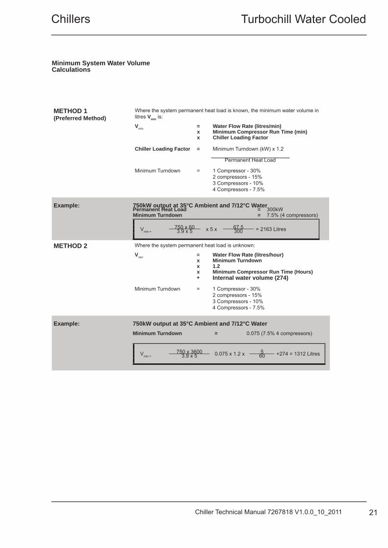
METHOD 1(Preferred Method)
Where the system permanent heat load is known, the minimum water volume in litres Vmin is:
Vmin = Water Flow Rate (litres/min) x Minimum Compressor Run Time (min) x Chiller Loading Factor
Chiller Loading Factor = Minimum Turndown (kW) x 1.2
Permanent Heat Load
Minimum Turndown = 1 Compressor - 30%2 compressors - 15%3 Compressors - 10%4 Compressors - 7.5%
Example: 750kW output at 35°C Ambient and 7/12°C WaterPermanent Heat Load = 300kWMinimum Turndown = 7.5% (4 compressors)
Vmin =750 x 60 x 5 x 67.5 = 2163 Litres3.9 x 5 300
METHOD 2 Where the system permanent heat load is unknown:
Vmin = Water Flow Rate (litres/hour) x Minimum Turndown x 1.2 x Minimum Compressor Run Time (Hours)
+ Internal water volume (274)
Minimum Turndown = 1 Compressor - 30%2 compressors - 15%3 Compressors - 10%4 Compressors - 7.5%
Example: 750kW output at 35°C Ambient and 7/12°C Water Minimum Turndown = 0.075 (7.5% 4 compressors)
Vmin =750 x 3600 0.075 x 1.2 x 5 +274 = 1312 Litres3.9 x 5 60
Minimum System Water Volume Calculations
TurboChill Water Cooled Chillers
22 Chiller Technical Manual 7267818 V1.0.0_10_2011
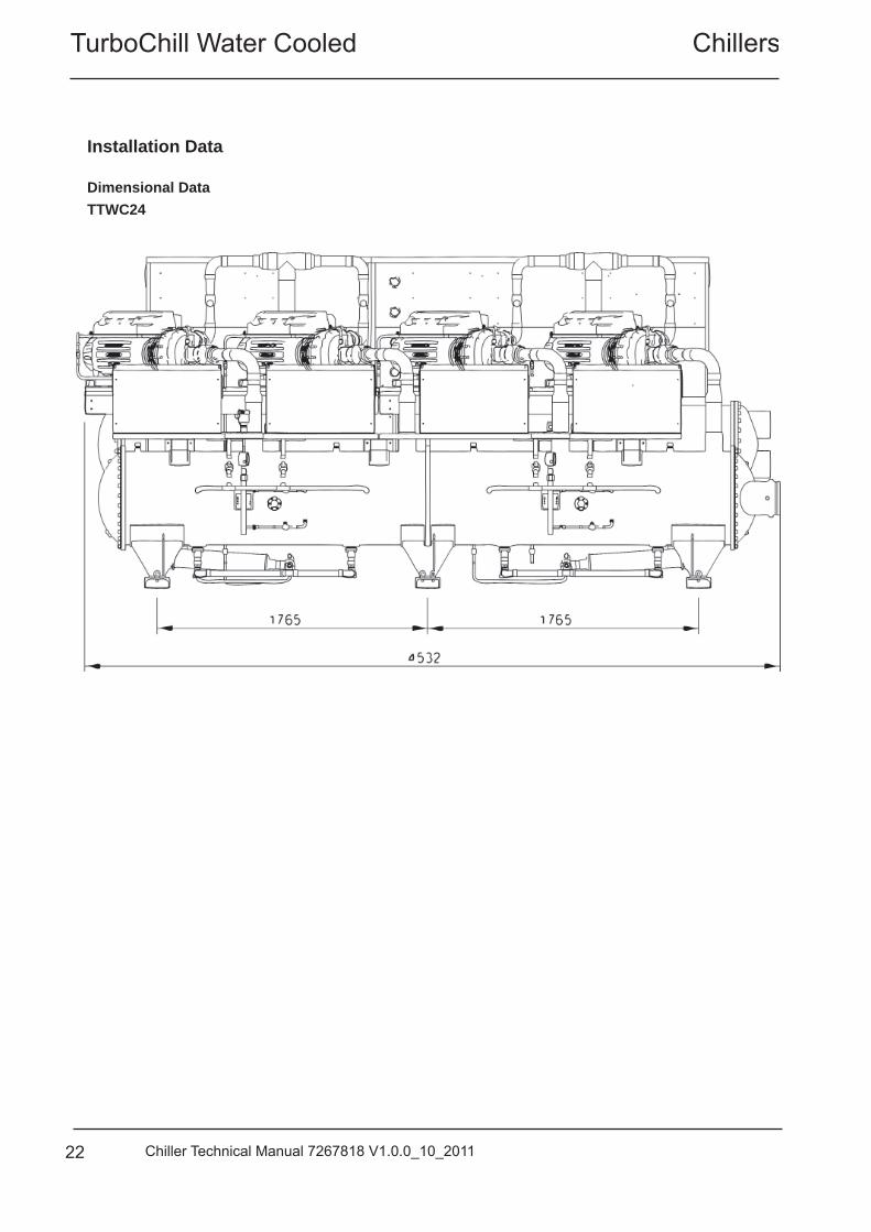
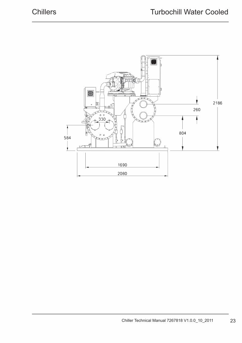
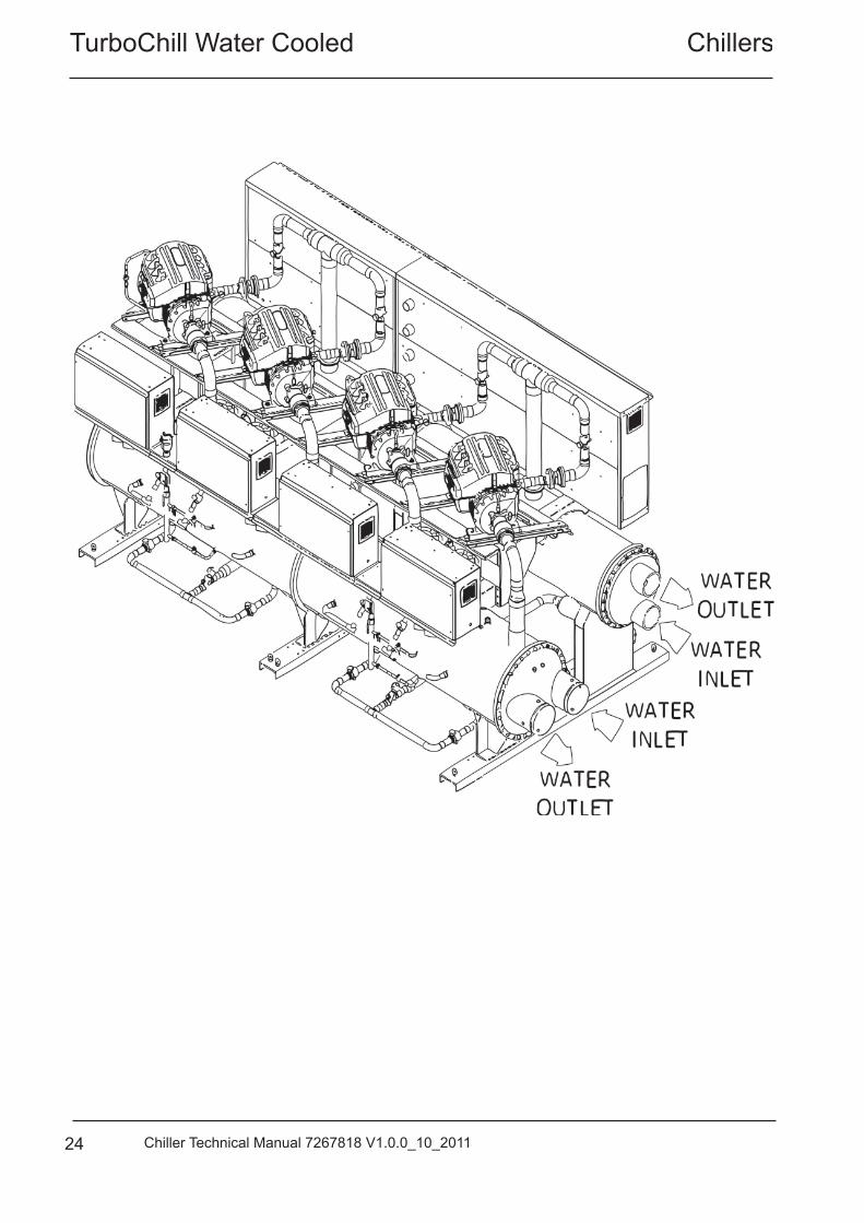
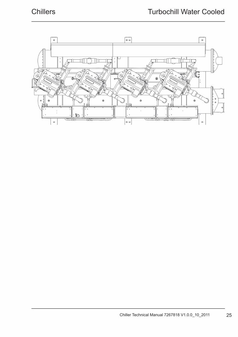
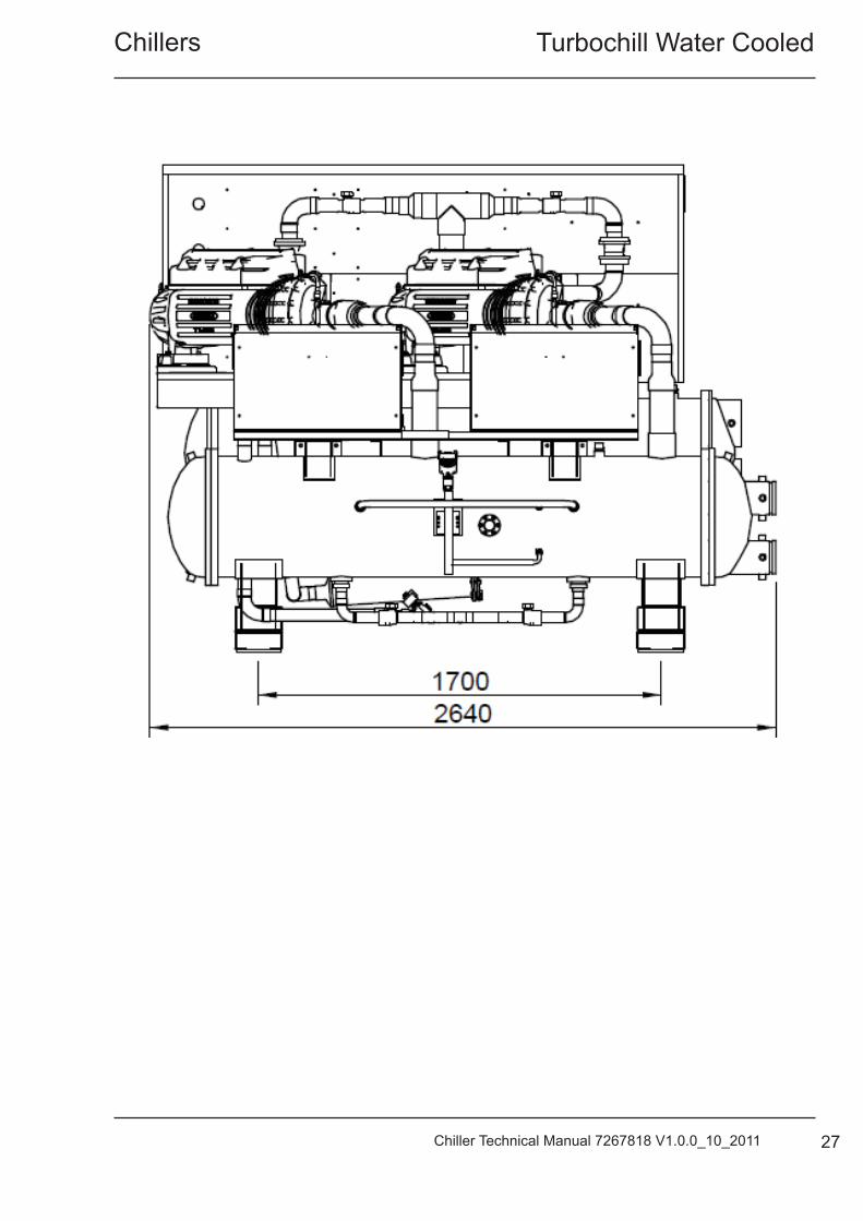
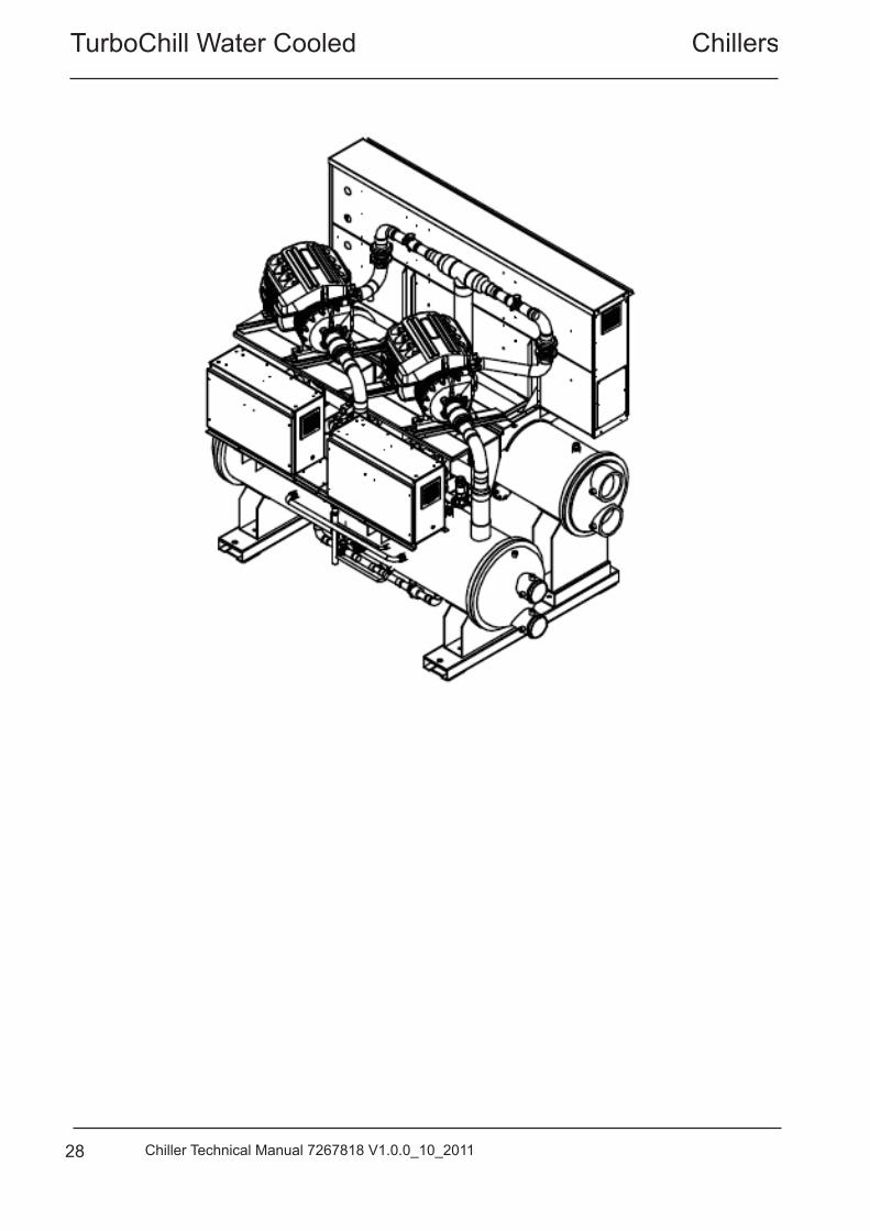
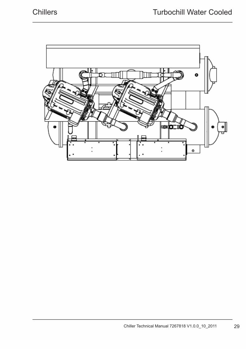
Dimensional Data
Installation Data
TTWC24
Turbochill Water CooledChillers
23Chiller Technical Manual 7267818 V1.0.0_10_2011
TurboChill Water Cooled Chillers
24 Chiller Technical Manual 7267818 V1.0.0_10_2011
Turbochill Water CooledChillers
25Chiller Technical Manual 7267818 V1.0.0_10_2011
TurboChill Water Cooled Chillers
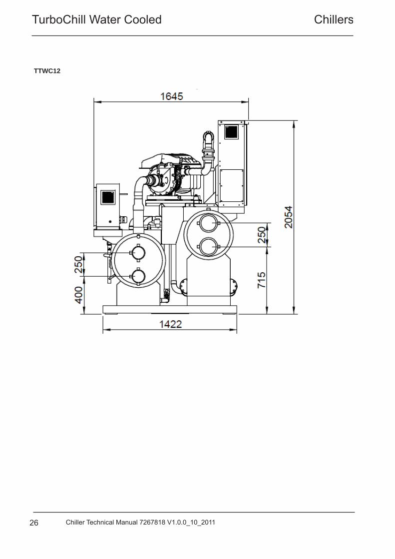
26 Chiller Technical Manual 7267818 V1.0.0_10_2011
TTWC12
Turbochill Water CooledChillers
27Chiller Technical Manual 7267818 V1.0.0_10_2011
TurboChill Water Cooled Chillers
28 Chiller Technical Manual 7267818 V1.0.0_10_2011
Turbochill Water CooledChillers
29Chiller Technical Manual 7267818 V1.0.0_10_2011
TurboChill Water Cooled Chillers
30 Chiller Technical Manual 7267818 V1.0.0_10_2011
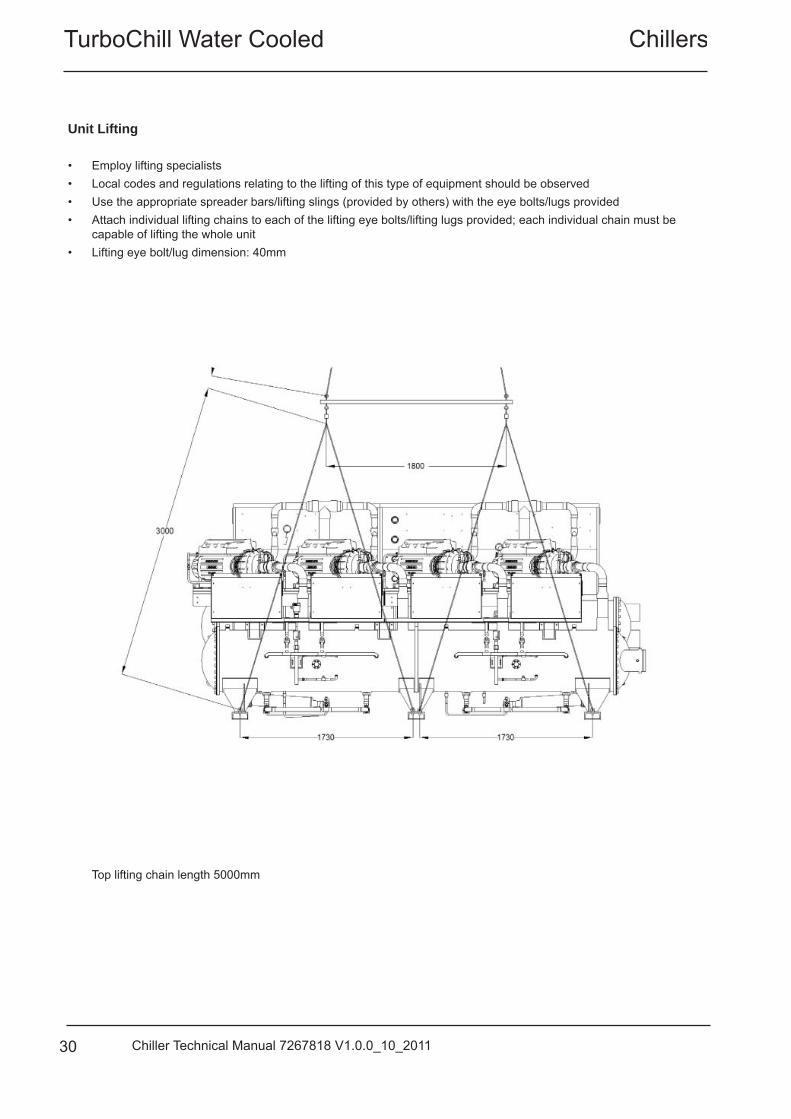
Unit Lifting
• Employ lifting specialists• Local codes and regulations relating to the lifting of this type of equipment should be observed• Use the appropriate spreader bars/lifting slings (provided by others) with the eye bolts/lugs provided• Attach individual lifting chains to each of the lifting eye bolts/lifting lugs provided; each individual chain must be
capable of lifting the whole unit• Lifting eye bolt/lug dimension: 40mm
Top lifting chain length 5000mm
Turbochill Water CooledChillers
31Chiller Technical Manual 7267818 V1.0.0_10_2011
PositioningThe installation position should be selected with the following points in mind: • Position on a stable and even base, levelled to ensure that the compressor operates correctly• Levelling should be to +/- 5mm• Where vibration transmission to the building structure is possible, fi t spring anti-vibration mounts
and fl exible water connections• Observe maintenance clearances• Pipe work and electrical connections are readily accessible• Increase maintenance clearances for side-enclosed or multiple unit applications
CAUTION
Prior to connecting services, ensure that the equipment is installed and completely level. Service & Maintenance Clearances
Application Distance from Overall Base Dimension (x) Single unit 1000mm (except control panel side 1500mm) Side-enclosed or multiple units 2000mm
TurboChill Water Cooled Chillers
32 Chiller Technical Manual 7267818 V1.0.0_10_2011
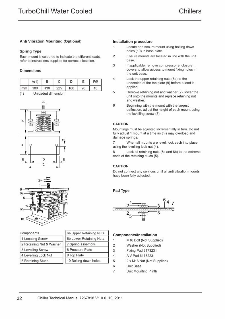
Anti Vibration Mounting (Optional)
Spring TypeEach mount is coloured to indicate the different loads, refer to instructions supplied for correct allocation.
Dimensions
A(1) B C D E FØ
mm 180 130 225 186 20 16(1) Unloaded dimension
B
A
C D E
F
E
2 1
6a 5
6b
10
9
8 7
3 4
Components
1 Locating Screw 2 Retaining Nut & Washer3 Levelling Screw4 Levelling Lock Nut5 Retaining Studs
6a Upper Retaining Nuts6b Lower Retaining Nuts7 Spring assembly8 Pressure Plate9 Top Plate10 Bolting-down holes
Installation procedure1 Locate and secure mount using bolting down holes (10) in base plate.2 Ensure mounts are located in line with the unit base.3 If applicable, remove compressor enclosure covers to allow access to mount fi xing holes in the unit base.4 Lock the upper retaining nuts (6a) to the underside of the top plate (9) before a load is applied.5 Remove retaining nut and washer (2), lower the unit onto the mounts and replace retaining nut and washer.6 Beginning with the mount with the largest defl ection, adjust the height of each mount using the levelling screw (3).
CAUTIONMountings must be adjusted incrementally in turn. Do not fully adjust 1 mount at a time as this may overload and damage springs.7 When all mounts are level, lock each into place using the levelling lock nut (4).8 Lock all retaining nuts (6a and 6b) to the extreme ends of the retaining studs (5).
CAUTIONDo not connect any services until all anti vibration mounts have been fully adjusted.
Pad Type
1 2 3 2
5
4
3
6 7
Components/Installation 1 M16 Bolt (Not Supplied)2 Washer (Not Supplied)3 Fixing Pad 61732314 A V Pad 61732235 2 x M16 Nut (Not Supplied)6 Unit Base7 Unit Mounting Plinth
Turbochill Water CooledChillers
33Chiller Technical Manual 7267818 V1.0.0_10_2011
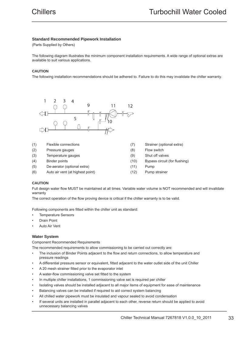
Standard Recommended Pipework Installation(Parts Supplied by Others) The following diagram illustrates the minimum component installation requirements. A wide range of optional extras are available to suit various applications. CAUTION The following installation recommendations should be adhered to. Failure to do this may invalidate the chiller warranty.
(1) Flexible connections(2) Pressure gauges(3) Temperature gauges(4) Binder points(5) De-aerator (optional extra)(6) Auto air vent (at highest point)
(7) Strainer (optional extra)(8) Flow switch(9) Shut off valves(10) Bypass circuit (for fl ushing)(11) Pump(12) Pump strainer
CAUTION Full design water fl ow MUST be maintained at all times. Variable water volume is NOT recommended and will invalidate warrantyThe correct operation of the fl ow proving device is critical if the chiller warranty is to be valid.
Following components are fi tted within the chiller unit as standard:• Temperature Sensors• Drain Point• Auto Air Vent
Water SystemComponent Recommended Requirements The recommended requirements to allow commissioning to be carried out correctly are:• The inclusion of Binder Points adjacent to the fl ow and return connections, to allow temperature and
pressure readings• A differential pressure sensor or equivalent, fi tted adjacent to the water outlet side of the unit Chiller• A 20 mesh strainer fi tted prior to the evaporator inlet• A water-fl ow commissioning valve set fi tted to the system• In multiple chiller installations, 1 commissioning valve set is required per chiller• Isolating valves should be installed adjacent to all major items of equipment for ease of maintenance• Balancing valves can be installed if required to aid correct system balancing• All chilled water pipework must be insulated and vapour sealed to avoid condensation• If several units are installed in parallel adjacent to each other, reverse return should be applied to avoid
unnecessary balancing valves
TurboChill Water Cooled Chillers
34 Chiller Technical Manual 7267818 V1.0.0_10_2011
Water SystemChilled water pipework and ancillary components must be installed in accordance with:• National and Local Water supply company standards• The manufacturer’s instructions are followed when fi tting ancillary components• The system liquid is treated to prevent corrosion and algae forming• In ambients of 0°C and below, where static water can be expected, or when water supply temperatures of +5°C or
below is required, the necessary concentration of Glycol or use of an electrical trace heater must be included• The schematic is referred to as a guide to ancillary recommendations CAUTION The unit water connections are NOT designed to support external pipework, pipework MUST be supported separately.
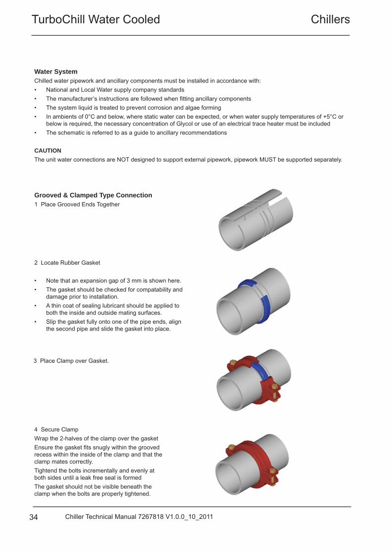
Grooved & Clamped Type Connection1 Place Grooved Ends Together
2 Locate Rubber Gasket • Note that an expansion gap of 3 mm is shown here.• The gasket should be checked for compatability and
damage prior to installation.• A thin coat of sealing lubricant should be applied to
both the inside and outside mating surfaces.• Slip the gasket fully onto one of the pipe ends, align
the second pipe and slide the gasket into place.
3 Place Clamp over Gasket.
4 Secure ClampWrap the 2-halves of the clamp over the gasketEnsure the gasket fi ts snugly within the grooved recess within the inside of the clamp and that the clamp mates correctly. Tightend the bolts incrementally and evenly at both sides until a leak free seal is formedThe gasket should not be visible beneath the clamp when the bolts are properly tightened.
Turbochill Water CooledChillers
35Chiller Technical Manual 7267818 V1.0.0_10_2011
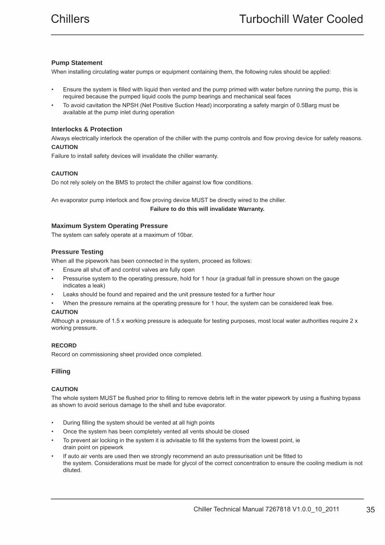
Pump Statement When installing circulating water pumps or equipment containing them, the following rules should be applied: • Ensure the system is fi lled with liquid then vented and the pump primed with water before running the pump, this is
required because the pumped liquid cools the pump bearings and mechanical seal faces• To avoid cavitation the NPSH (Net Positive Suction Head) incorporating a safety margin of 0.5Barg must be
available at the pump inlet during operation Interlocks & Protection Always electrically interlock the operation of the chiller with the pump controls and fl ow proving device for safety reasons.CAUTION Failure to install safety devices will invalidate the chiller warranty. CAUTION Do not rely solely on the BMS to protect the chiller against low fl ow conditions.
An evaporator pump interlock and fl ow proving device MUST be directly wired to the chiller. Failure to do this will invalidate Warranty.
Maximum System Operating Pressure The system can safely operate at a maximum of 10bar. Pressure Testing When all the pipework has been connected in the system, proceed as follows:• Ensure all shut off and control valves are fully open• Pressurise system to the operating pressure, hold for 1 hour (a gradual fall in pressure shown on the gauge
indicates a leak)• Leaks should be found and repaired and the unit pressure tested for a further hour • When the pressure remains at the operating pressure for 1 hour, the system can be considered leak free. CAUTION Although a pressure of 1.5 x working pressure is adequate for testing purposes, most local water authorities require 2 x working pressure. RECORD Record on commissioning sheet provided once completed.
Filling CAUTION The whole system MUST be fl ushed prior to fi lling to remove debris left in the water pipework by using a fl ushing bypass as shown to avoid serious damage to the shell and tube evaporator. • During fi lling the system should be vented at all high points• Once the system has been completely vented all vents should be closed• To prevent air locking in the system it is advisable to fi ll the systems from the lowest point, ie
drain point on pipework• If auto air vents are used then we strongly recommend an auto pressurisation unit be fi tted to
the system. Considerations must be made for glycol of the correct concentration to ensure the cooling medium is not diluted.
TurboChill Water Cooled Chillers
36 Chiller Technical Manual 7267818 V1.0.0_10_2011
Electrical
IMPORTANT Please refer to the electrical wiring diagrams provided for installation. ALL work MUST be carried out by technically trained competent personnel. The equipment contains live electrical and moving parts, ISOLATE prior to maintenance or repair work. The unit isolators DO NOT isolate the incoming mains supply, but isolate the individual electrical circuits. Isolate REMOTELY the mains incoming supply to the BUSBAR chamber prior to maintenance or repair work.
General As standard the equipment is designed for 400V, 3 phase, 3 wire 50Hz and a separate permanent 230V, 1 phase, 50Hz supply, to all relevant IEE regulations, British standards and IEC requirementsThe control voltage to the interlocks is 24V, always size the low voltage interlock and protection cabling for a maximum voltage drop of 2V
Avoid large voltage drops on cable runs, particularly low voltage wiring CAUTIONThe Emergency Stop MUST NOT be used to stop the chiller other than in the event of an emergency. A fused and isolated electrical supply of the appropriate phase, frequency and voltage should be installed. Wires should be capable of carrying the maximum load current under non-fault conditions at the stipulated voltage.
Ensure correct phase rotation.
Unit controls supply is supported by an on board UPS to ensure control operation is maintained in the event of a system shut down in a power failure situation. Power will be maintained until mains power is reinstated for a maximum period of 10 minutes.
Turbochill Water CooledChillers
37Chiller Technical Manual 7267818 V1.0.0_10_2011
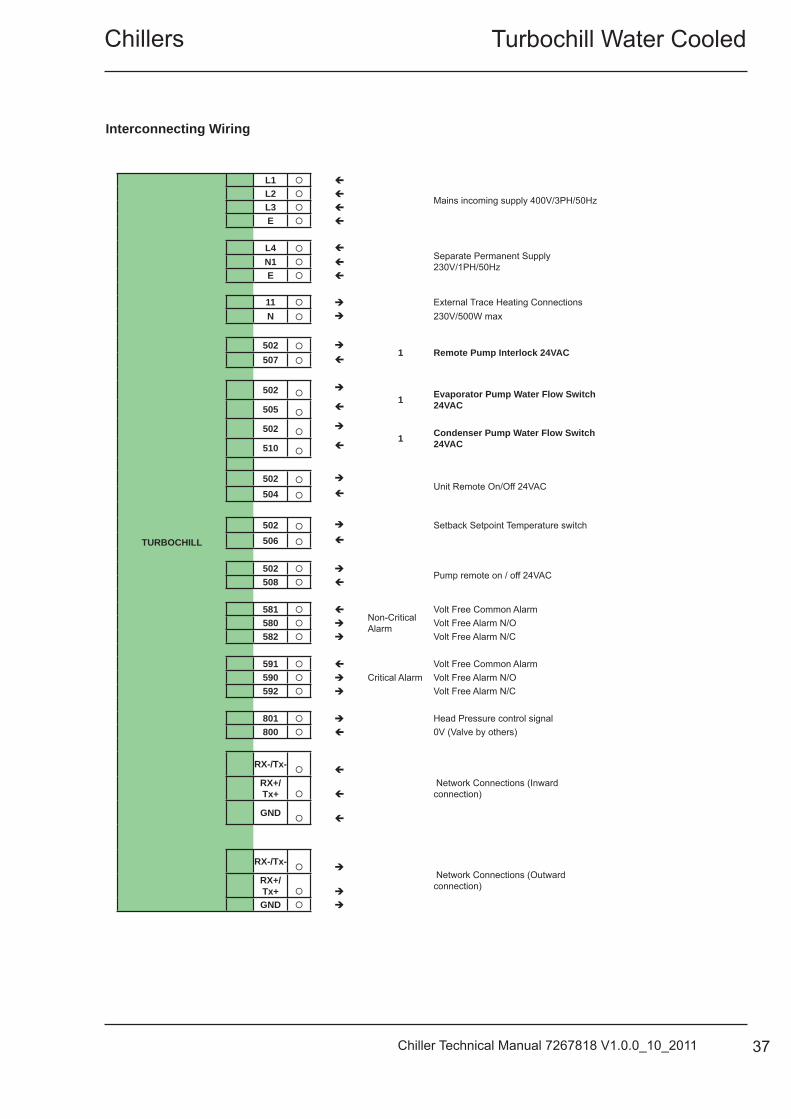
TURBOCHILL
L1
Mains incoming supply 400V/3PH/50HzL2
L3
E
L4 Separate Permanent Supply 230V/1PH/50HzN1
E
11 External Trace Heating ConnectionsN 230V/500W max
502 1 Remote Pump Interlock 24VAC
507
502
1 Evaporator Pump Water Flow Switch 24VAC505
502
1 Condenser Pump Water Flow Switch 24VAC510
502 Unit Remote On/Off 24VAC
504
Setback Setpoint Temperature switch502
506
502 Pump remote on / off 24VAC
508
581 Non-Critical Alarm
Volt Free Common Alarm580 Volt Free Alarm N/O582 Volt Free Alarm N/C
591
Critical AlarmVolt Free Common Alarm
590 Volt Free Alarm N/O592 Volt Free Alarm N/C
801 Head Pressure control signal800 0V (Valve by others)
RX-/Tx-
Network Connections (Inward connection)
RX+/Tx+
GND
RX-/Tx-
Network Connections (Outward connection)RX+/
Tx+
GND
Interconnecting Wiring
TurboChill Water Cooled Chillers
38 Chiller Technical Manual 7267818 V1.0.0_10_2011
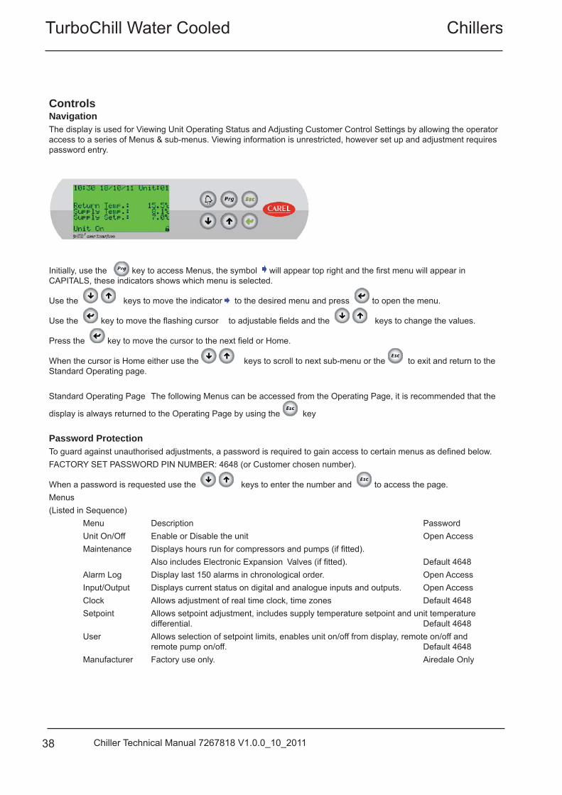
ControlsNavigation The display is used for Viewing Unit Operating Status and Adjusting Customer Control Settings by allowing the operator access to a series of Menus & sub-menus. Viewing information is unrestricted, however set up and adjustment requires password entry.
Initially, use the key to access Menus, the symbol will appear top right and the fi rst menu will appear in CAPITALS, these indicators shows which menu is selected.
Use the keys to move the indicator to the desired menu and press to open the menu.
Use the key to move the fl ashing cursor to adjustable fi elds and the keys to change the values.
Press the key to move the cursor to the next fi eld or Home.
When the cursor is Home either use the keys to scroll to next sub-menu or the to exit and return to the Standard Operating page.
Standard Operating Page The following Menus can be accessed from the Operating Page, it is recommended that the
display is always returned to the Operating Page by using the key Password Protection To guard against unauthorised adjustments, a password is required to gain access to certain menus as defi ned below.FACTORY SET PASSWORD PIN NUMBER: 4648 (or Customer chosen number).
When a password is requested use the keys to enter the number and to access the page.Menus (Listed in Sequence) Menu Description Password Unit On/Off Enable or Disable the unit Open Access Maintenance Displays hours run for compressors and pumps (if fi tted). Also includes Electronic Expansion Valves (if fi tted). Default 4648 Alarm Log Display last 150 alarms in chronological order. Open Access Input/Output Displays current status on digital and analogue inputs and outputs. Open Access Clock Allows adjustment of real time clock, time zones Default 4648 Setpoint Allows setpoint adjustment, includes supply temperature setpoint and unit temperature differential. Default 4648 User Allows selection of setpoint limits, enables unit on/off from display, remote on/off and remote pump on/off. Default 4648 Manufacturer Factory use only. Airedale Only
Turbochill Water CooledChillers
39Chiller Technical Manual 7267818 V1.0.0_10_2011
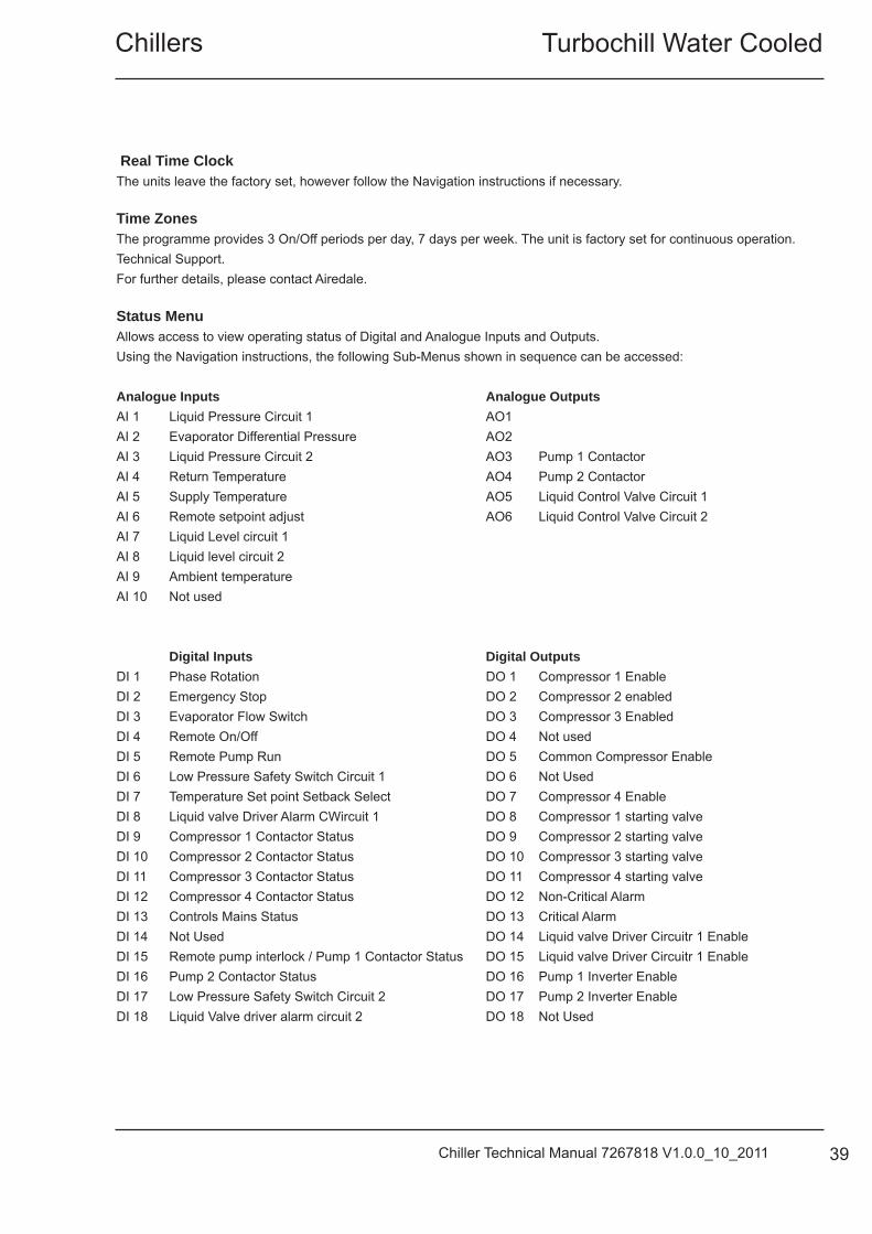
Real Time Clock The units leave the factory set, however follow the Navigation instructions if necessary.
Time Zones The programme provides 3 On/Off periods per day, 7 days per week. The unit is factory set for continuous operation.Technical Support.For further details, please contact Airedale.
Status MenuAllows access to view operating status of Digital and Analogue Inputs and Outputs.Using the Navigation instructions, the following Sub-Menus shown in sequence can be accessed:
Analogue Inputs Analogue OutputsAI 1 Liquid Pressure Circuit 1 AO1 AI 2 Evaporator Differential Pressure AO2 AI 3 Liquid Pressure Circuit 2 AO3 Pump 1 ContactorAI 4 Return Temperature AO4 Pump 2 ContactorAI 5 Supply Temperature AO5 Liquid Control Valve Circuit 1AI 6 Remote setpoint adjust AO6 Liquid Control Valve Circuit 2AI 7 Liquid Level circuit 1 AI 8 Liquid level circuit 2 AI 9 Ambient temperature AI 10 Not used Digital Inputs Digital OutputsDI 1 Phase Rotation DO 1 Compressor 1 EnableDI 2 Emergency Stop DO 2 Compressor 2 enabledDI 3 Evaporator Flow Switch DO 3 Compressor 3 EnabledDI 4 Remote On/Off DO 4 Not usedDI 5 Remote Pump Run DO 5 Common Compressor EnableDI 6 Low Pressure Safety Switch Circuit 1 DO 6 Not UsedDI 7 Temperature Set point Setback Select DO 7 Compressor 4 EnableDI 8 Liquid valve Driver Alarm CWircuit 1 DO 8 Compressor 1 starting valveDI 9 Compressor 1 Contactor Status DO 9 Compressor 2 starting valveDI 10 Compressor 2 Contactor Status DO 10 Compressor 3 starting valveDI 11 Compressor 3 Contactor Status DO 11 Compressor 4 starting valveDI 12 Compressor 4 Contactor Status DO 12 Non-Critical AlarmDI 13 Controls Mains Status DO 13 Critical AlarmDI 14 Not Used DO 14 Liquid valve Driver Circuitr 1 EnableDI 15 Remote pump interlock / Pump 1 Contactor Status DO 15 Liquid valve Driver Circuitr 1 EnableDI 16 Pump 2 Contactor Status DO 16 Pump 1 Inverter EnableDI 17 Low Pressure Safety Switch Circuit 2 DO 17 Pump 2 Inverter EnableDI 18 Liquid Valve driver alarm circuit 2 DO 18 Not Used
TurboChill Water Cooled Chillers
40 Chiller Technical Manual 7267818 V1.0.0_10_2011
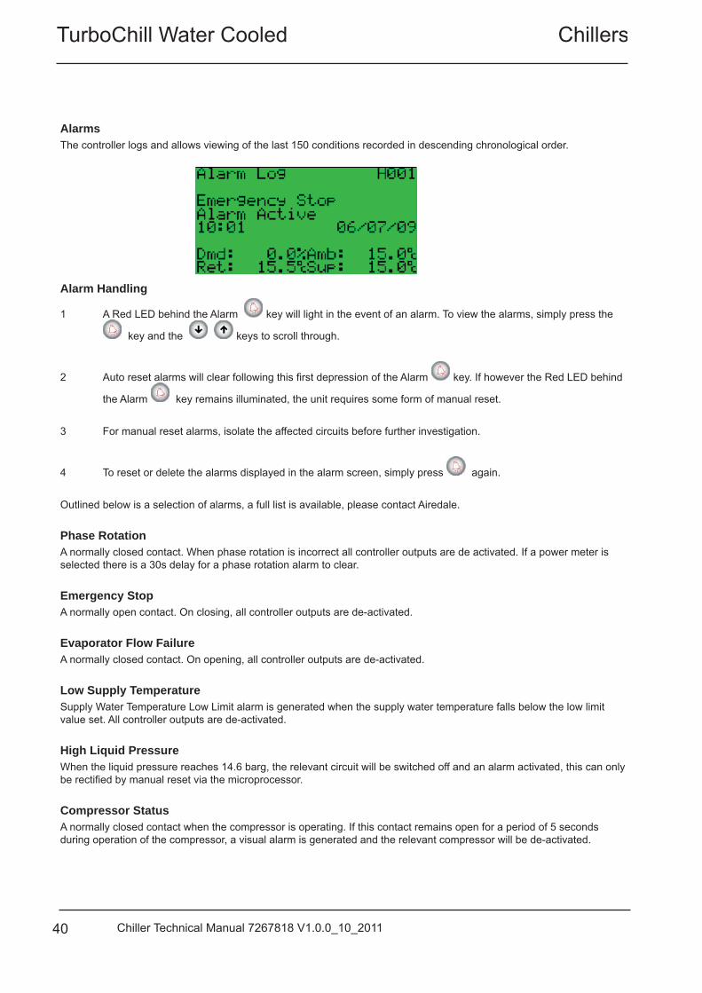
Alarms The controller logs and allows viewing of the last 150 conditions recorded in descending chronological order.
Alarm Handling
1 A Red LED behind the Alarm key will light in the event of an alarm. To view the alarms, simply press the
key and the keys to scroll through.
2 Auto reset alarms will clear following this fi rst depression of the Alarm key. If however the Red LED behind
the Alarm key remains illuminated, the unit requires some form of manual reset. 3 For manual reset alarms, isolate the affected circuits before further investigation.
4 To reset or delete the alarms displayed in the alarm screen, simply press again. Outlined below is a selection of alarms, a full list is available, please contact Airedale. Phase Rotation A normally closed contact. When phase rotation is incorrect all controller outputs are de activated. If a power meter is selected there is a 30s delay for a phase rotation alarm to clear. Emergency Stop A normally open contact. On closing, all controller outputs are de-activated. Evaporator Flow Failure A normally closed contact. On opening, all controller outputs are de-activated. Low Supply Temperature Supply Water Temperature Low Limit alarm is generated when the supply water temperature falls below the low limit value set. All controller outputs are de-activated. High Liquid Pressure When the liquid pressure reaches 14.6 barg, the relevant circuit will be switched off and an alarm activated, this can only be rectifi ed by manual reset via the microprocessor. Compressor Status A normally closed contact when the compressor is operating. If this contact remains open for a period of 5 seconds during operation of the compressor, a visual alarm is generated and the relevant compressor will be de-activated.
Turbochill Water CooledChillers
41Chiller Technical Manual 7267818 V1.0.0_10_2011
CommissioningTo be read in conjunction with the commissioning sheets provided. CAUTION Please ensure all documents have been completed correctly and return to Airedale Technical Support immediately to validate warranty. Pre Commissioning Checklist CAUTIONALL work MUST be carried out by Technically Trained competent personnel. The equipment contains live electrical and moving parts, ISOLATE prior to maintenance or repair work. The door interlocking MCCB should be in the OFF position and the auxiliary alarm contact from the MCCB should be linked out. All pipework is complete and insulated where necessary. IMPORTANT Check phase rotation of electrical supply prior to running compressor as compressor is direction sensitive. Refrigerant standing pressureThe refrigerant charge is to be checked to ensure correct charge. This is done by measuring the liquid line standing pressure and temperature. This can then be compared to refrigerant data tables or Refrigerant Comparator.
Standing pressures can only be measured in the liquid state.
TurboChill Water Cooled Chillers
42 Chiller Technical Manual 7267818 V1.0.0_10_2011
Commissioning Procedure
Electrical connections Ensure all electrical connection are tight and correctly terminated.
External fuses/ MCB’s Check that the correct electrical supply rating is available to the unit
Electrical continuityBefore electrical power is applied to the unit. Electrical continuity checks must the carried out on the 3 phase power.
Phase rotation Check that the electrical phase rotation is correct. Components in the unit will malfunction with incorrect phase rotation.
Electrical earthing Check that the unit is correctly earthed.
Remote on/off To ensure that the unit does not start whist doing the pre-commissioning checks the remote on/off switch should be in the OFF state.
Voltage • Measure the voltage at the following points and record on the commissioning sheet• Voltage at busbar• Dedicated power supply• Voltage at permanent supply• Control voltage at transformer (min 22.5V, max 25V)
The voltage measurements should be carried out with the unit MCB’s turned off.
WatersideGeneral water pipeworkEnsure that the system water pipework is clean from debris. If a fl ush and bypass circuit is included ensure that the system is fl ushed prior to water entering the unit.
Water fi lter fi ttedEnsure that the water fi lter is fi tted and clean.
Water fl ow rateCheck that the design water fl owrate is available to the unit.
Waterside pressure dropMeasure the waterside pressure drop of the unit ensuring that the pump (if fi tted) is operating.
Turbochill Water CooledChillers
43Chiller Technical Manual 7267818 V1.0.0_10_2011
Glycol strength Check and record the glycol type and strength. Low levels of glycol can cause freeze up problems when operating at low temperatures or during the unit off state during cold ambient conditions.
Glycol concentration is measured by use of a Refractometer.
Differential pressure sensorEnsure that the differential pressure sensor operates satisfactory; the best way to do this is to reduce the Flow to the Chiller.• From pressure curves determine the design Flowrate/ pressure drop• Make sure that any effects of glycol in the system are taken into account (Flowrate and pressure drop).• Input into the controller the reduced pressure drop (kPa) value (Normally 80% of design Flowrate)
Once this value is programmed into the controller the water Flowrate can be reduced to verify that the low fl ow alarm is activated.
Ensure that the tubes connected to the sensor are insulated.
Low supply water trip To check operation of the low temperature trip the following procedure can be carried out.With the unit running increase the low temperature limit to the actual supply water temperature.This will trip the unit in a safe manner without risk of freezing the evaporator
Return the low temperature limit to correct value after test. (this will allow the unit to operate correctly)
Pump interlockThe pump interlock is fi tted and functioning correctly.
Controls Controller Record on the commissioning sheet the controller serial numbers details.• Controller type• Address• Serial number• Bios• BootAlso record any expansion valve driver serial numbers.
Controller settings The following controller settings are to be recorded on the commissioning sheet.
• Head pressure differential (Barg)• Minimum suction pressure (Barg)• Supply water set point (Summer/ Day) (°C)• Supply water set point (Winter/ Night) (°C)• Minimum supply water temperature (°C)
TurboChill Water Cooled Chillers
44 Chiller Technical Manual 7267818 V1.0.0_10_2011
Refrigeration Compressor Record on the commissioning sheet compressor details• Type• Serial numbers.• Overload settings Operating conditions
• Record the following operating conditions of the unit at stable conditions. • Suction pressure (bar)• Liquid Pressure (Bar)• Discharge pressure (Bar)• Suction temperature (°C)• Liquid temperature (°C)• Discharge temperature (°C)• Superheat (°C)• Sub cooling (°C)• Evaporator Water return temperature (°C)• Evaporator Water supply temperature (°C)• Condenser Water return temperature (°C)• Condenser Water supply temperature (°C)
The supply and return water temperatures should be taken and recorded in both full and part load conditions approximately 1m away from the unit.
Liquid line sight glass Record the status of the liquid line sight glass• Clear/ fl ashing• Wet/dry (Yellow or Green) HP/ LP Trips Check operating of HP/LP cut-out, settings LP cut-out – (Auto reset for 3 times when the Low Pressure is detected for 6 minutes)Low pressure cut-out – 0.5 bar (7 psig )Differential 2.0bar (29 psig)HP switch – (manual reset): High pressure switch – 14.6 bar (212 psig)Differential 2.0 bar (29 psig)HP limiting function 13.6 bar
Turbochill Water CooledChillers
45Chiller Technical Manual 7267818 V1.0.0_10_2011
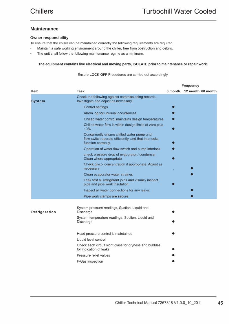
Maintenance
Item TaskFrequency
6 month 12 month 60 month
SystemCheck the following against commissioning records. Investigate and adjust as necessary.
Control settings
Alarm log for unusual occurrences
Chilled water control maintains design temperatures
Chilled water fl ow is within design limits of zero plus 10%
Concurrently ensure chilled water pump and fl ow switch operate effi ciently, and that interlocks function correctly.
Operation of water fl ow switch and pump interlock
check pressure drop of evaporator / condenser. Clean where appropriate
Check glycol concentration if appropriate. Adjust as necessary .
Clean evaporator water strainer.
Leak test all refrigerant joins and visually inspect pipe and pipe work insulation
Inspect all water connections for any leaks.
Pipe work clamps are secure
RefrigerationSystem pressure readings, Suction, Liquid and Discharge
System temperature readings, Suction, Liquid and Discharge
Head pressure control is maintained
Liquid level controlCheck each circuit sight glass for dryness and bubbles for indication of leaks
Pressure relief valves
F-Gas inspection
Owner responsibilityTo ensure that the chiller can be maintained correctly the following requirements are required.• Maintain a safe working environment around the chiller, free from obstruction and debris.• The unit shall follow the following maintenance regime as a minimum.
The equipment contains live electrical and moving parts, ISOLATE prior to maintenance or repair work.
Ensure LOCK OFF Procedures are carried out accordingly.
TurboChill Water Cooled Chillers
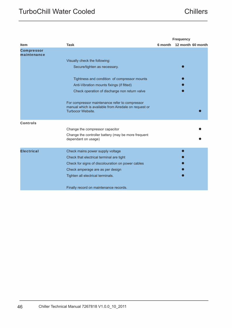
46 Chiller Technical Manual 7267818 V1.0.0_10_2011
Item TaskFrequency
6 month 12 month 60 monthCompressor maintenance
Visually check the following:
Secure/tighten as necessary.
Tightness and condition of compressor mounts
Anti-Vibration mounts fi xings (if fi tted)
Check operation of discharge non return valve
For compressor maintenance refer to compressor manual which is available from Airedale on request or Turbocor Website.
Controls
Change the compressor capacitor
Change the controller battery (may be more frequent dependant on usage)
Electrical Check mains power supply voltage
Check that electrical terminal are tight
Check for signs of discolouration on power cables
Check amperage are as per design
Tighten all electrical terminals.
Finally record on maintenance records.
Turbochill Water CooledChillers
47Chiller Technical Manual 7267818 V1.0.0_10_2011
Maintenance Advice
Compressor Refrigerant RecoveryIn the event that the compressor is required to be recovered of refrigerant, ensure that the start loop shut off valve is closed.
Do not rely on the solenoid valve to isolate refrigerant.
The solenoid valve will eventually pass refrigerant if a higher pressure is on the normally low side of the valve.
Compressor Non return valveCheck the operation of the non return valve. The internal spring must be located in the retaining groove.
Pressure relief valve
In line with EN 378, Airedale recommends that the valve be replaced at least every 5 years.These intervals may have to be reduced if other regulations apply.
The pressure relief is fi tted to the unit by a three way dual shut off valve. This valve enables the pressure relief to be changed without the need for refrigerant recovery.
The valve is positioned normally one way or the other. To change a pressure relief valve back seat or forward seat the valve to seal the required port that is being changed.
Dont forget to set the valve into the centre to chaeck that the valve does not leak refrigerant. Then select one of the pressure relief valves and open that port. Take extreme care that the correct port is selected.
CAUTIONPut the cap on the three way valvePerform an F-Gas inspection35
Shut Down Periods For periods of winter shut down the following precautions are recommended:• Close the liquid and discharge ball valve• Cap service ports• Turn off electrical circuits• Drain the water from the unit.
TurboChill Water Cooled Chillers
48 Chiller Technical Manual 7267818 V1.0.0_10_2011
Storage Recommendations
Airedale recommends that equipment should be stored in an ambient protected warehouse facility.
• The unit should be stored within a heated warehouse ensuring that the temperature does not fall below 0°C.• All water should be drained from the evaporator• Refrigerant line shut off valves are closed.
Before turning the unit on after extended periods of storage the following checks / procedures must be carried out over and above any commissioning checks.
Any low temperature protection devices must be turned on for a minimum of 8 hour.
These include• Compressor crankcase heaters.• Panel heaters.• Electric trace heating.
Checks must be carried out for the operation of unit components
Waterside• 3 way valve• Check that fl ow switches operate correctly.• Check that differential pressure sensor operates.
Electrical• Electrical seals and glands are satisfactory and have not cracked• All electrical terminal boxes are free from moisture.• All cable insulation is satisfactory and does not have any signs of damage.• Refrigeration
• Ensure all valves are open• Carry out an F-gas inspection ensuring no refrigerant leaks.
Turbochill Water CooledChillers
49Chiller Technical Manual 7267818 V1.0.0_10_2011
Head Offi ceAiredale International Air Conditioning Ltd
Leeds RoadRawdon
Leeds LS19 6JYTel: +44 (0) 113 2391000Fax:+44 (0) 113 2507219
E-mail [email protected] www.airedale.com