Embed Size (px)
Citation preview
INS310-011x(A) Page 1 of 18 Rev. 03/02/17
TURBOCHARGER UPGRADE; N55
INSTALLATION INSTRUCTIONS
PART NUMBER D310-0110, D310-0110A, or D310-0115
APPLICATION: 2014-16 F22 M235i & xDrive coupe
2015-16 F23 M235i & xDrive convertible
2012-15 F30 335i & xDrive sedan
2014-15 F34 335i xDrive Gran Turismo
2014-16 F32 435i & xDrive coupe
2015-16 F36 435i & xDrive Gran Coupe
Congratulations for being selective enough to use a Dinan Turbocharger Upgrade. We
have spent many hours developing this kit to assure that you will receive maximum
performance and durability with minimum difficulty in installation. Please take the time
to read these instructions and call us if you have any difficulties during the installation.
________________________________________________________________
PARTS LIST
Qty Part # Description
1 D313-0110(A) Dinan Turbocharger; N55 Elec, or
1 D313-0115 Dinan Turbocharger; N55 Vac
1 D313-0116 N55 Turbo Hardware Kit
________________________________________________________________
INS310-011x(A) Page 2 of 18 Rev. 03/02/17
IMPORTANT NOTES:
Turbocharger replacement requires a high level of automotive mechanical skill,
experience and tools. There is a risk of damage to both the turbocharger being removed, as well as the new turbocharger, if adequate care is not taken. Installation
of the Dinan turbocharger assumes the user has a sufficient level of skill, experience,
and tools, to complete this task successfully.
For rear wheel drive vehicles: These instructions discuss turbocharger replacement
on an N55 engine without removal of the exhaust manifold. This is a much quicker
process than the standard BMW turbocharger replacement procedure. The
hardware included in this kit is designed for Dinan's shorter procedure.
For xDrive vehicles: Due to limited access, turbocharger replacement on xDrive vehicles must follow recommended BMW procedure. Because the exhaust manifold
is removed to access the turbocharger, additional hardware will be required for
installation. Please have these components on hand before beginning installation, or
contact your sales representative for Dinan hardware kit D313-0117.
For xDrive vehicles with vacuum-controlled wastegate turbochargers: The
wastegate linkage must be adjusted for proper operation. This adjustment is not
documented in the standard BMW turbocharger replacement procedure. The best
opportunity to perform the adjustment is when the Dinan turbocharger has been
installed onto the manifold, but before this assembly is reinstalled in the car. While
the assembly is on the workbench, follow the wastegate adjustment procedure at
the end of these instructions.
For all vehicles with electronic wastegates: The wastegate must be adjusted per
BMW procedure for proper operation. Wastegate adjustment requires factory-level
tools such as BMW ISTA (or equivalent). Please ensure that these tools are
available prior to beginning installation.
DO NOT WORK ON VEHICLES SUPPORTED BY A JACK ONLY. USE SECURE
JACK STANDS!
INS310-011x(A) Page 3 of 18 Rev. 03/02/17
INSTALLATION:
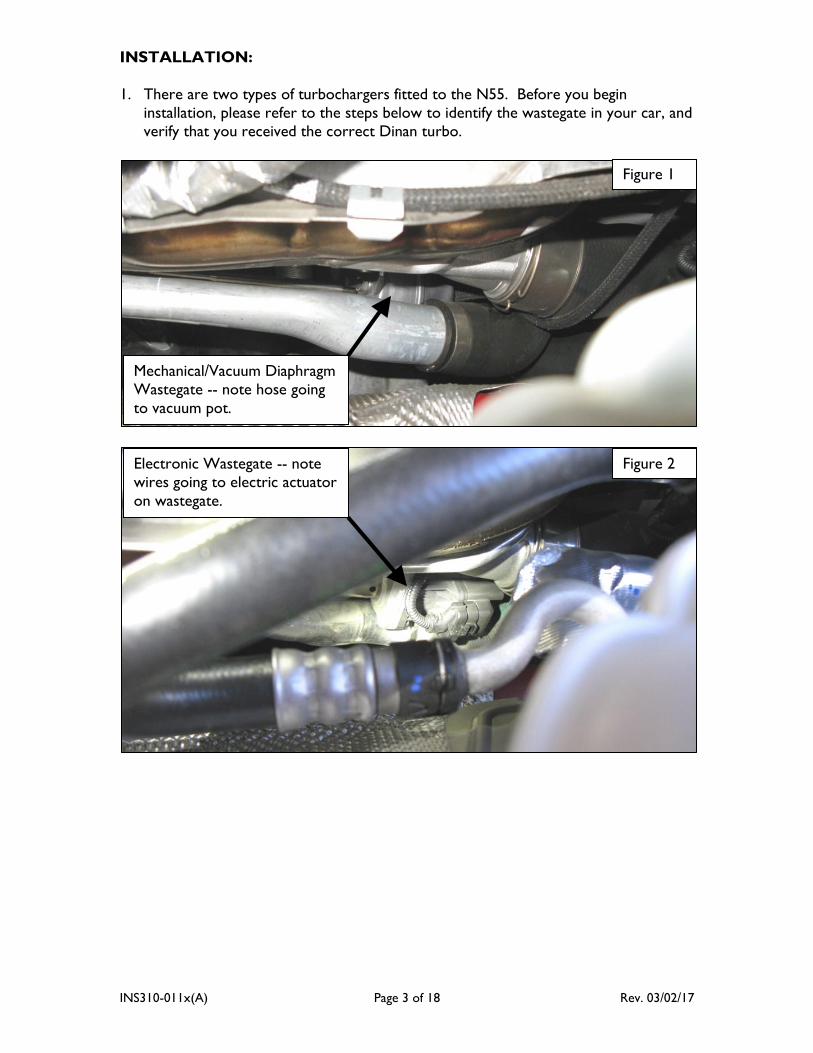
1. There are two types of turbochargers fitted to the N55. Before you begin
installation, please refer to the steps below to identify the wastegate in your car, and
verify that you received the correct Dinan turbo.
Figure 1
Mechanical/Vacuum Diaphragm
Wastegate -- note hose going
to vacuum pot.
Figure 2 Electronic Wastegate -- note
wires going to electric actuator
on wastegate.
INS310-011x(A) Page 4 of 18 Rev. 03/02/17
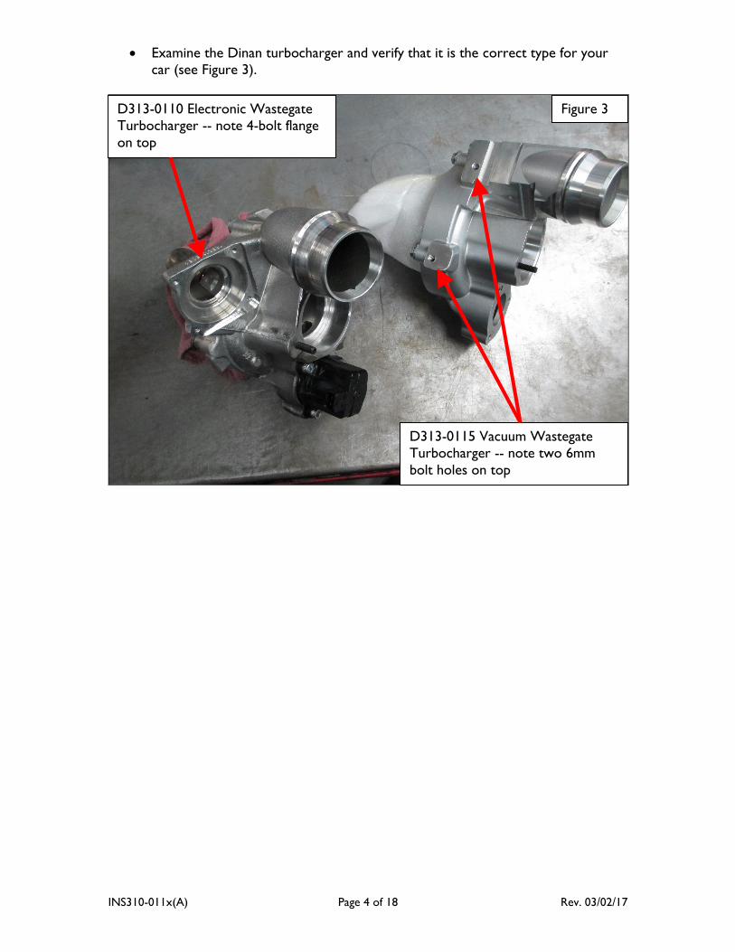
Examine the Dinan turbocharger and verify that it is the correct type for your
car (see Figure 3).
Figure 3 D313-0110 Electronic Wastegate
Turbocharger -- note 4-bolt flange
on top
D313-0115 Vacuum Wastegate
Turbocharger -- note two 6mm
bolt holes on top
INS310-011x(A) Page 5 of 18 Rev. 03/02/17
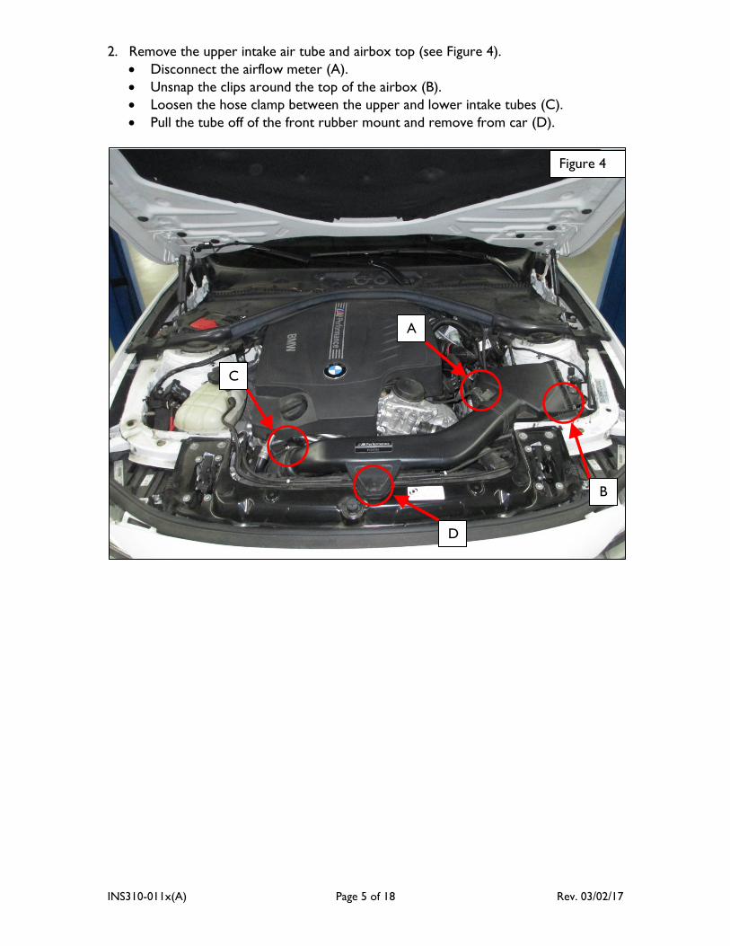
2. Remove the upper intake air tube and airbox top (see Figure 4).
Disconnect the airflow meter (A).
Unsnap the clips around the top of the airbox (B).
Loosen the hose clamp between the upper and lower intake tubes (C).
Pull the tube off of the front rubber mount and remove from car (D).
Figure 4
A
D
C
B
INS310-011x(A) Page 6 of 18 Rev. 03/02/17
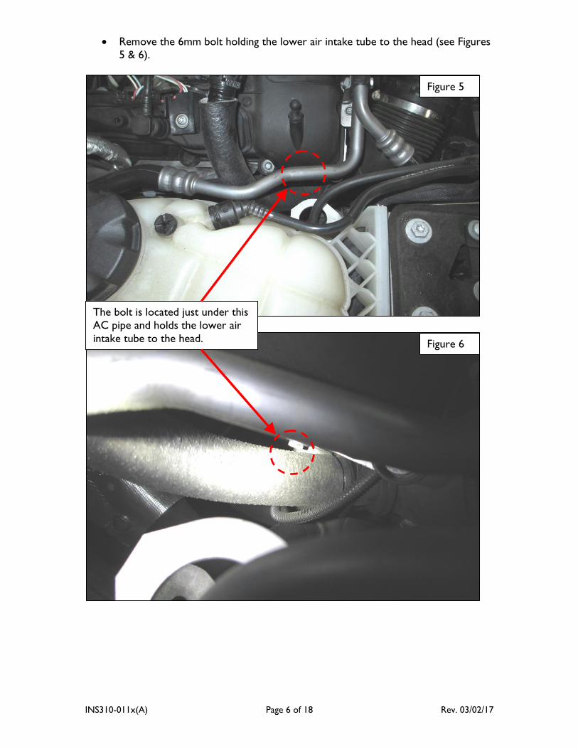
Remove the 6mm bolt holding the lower air intake tube to the head (see Figures
5 & 6).
Figure 5
Figure 6
The bolt is located just under this
AC pipe and holds the lower air
intake tube to the head.
INS310-011x(A) Page 7 of 18 Rev. 03/02/17
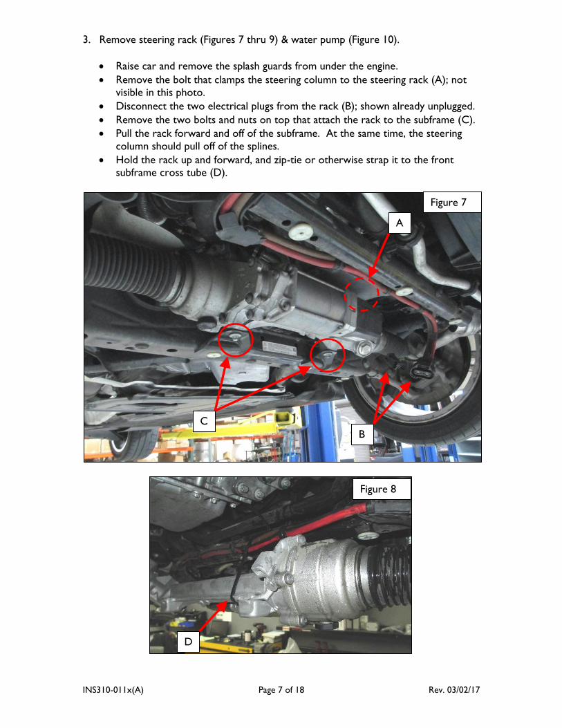
3. Remove steering rack (Figures 7 thru 9) & water pump (Figure 10).
Raise car and remove the splash guards from under the engine.
Remove the bolt that clamps the steering column to the steering rack (A); not visible in this photo.
Disconnect the two electrical plugs from the rack (B); shown already unplugged.
Remove the two bolts and nuts on top that attach the rack to the subframe (C).
Pull the rack forward and off of the subframe. At the same time, the steering
column should pull off of the splines.
Hold the rack up and forward, and zip-tie or otherwise strap it to the front subframe cross tube (D).
Figure 8
D
Figure 7
A
B
C
INS310-011x(A) Page 8 of 18 Rev. 03/02/17
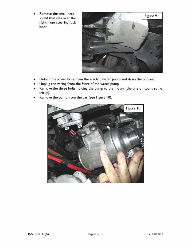
Remove the small heat
shield that was over the
right-front steering rack
boot.
Detach the lower hose from the electric water pump and drain the coolant.
Unplug the wiring from the front of the water pump.
Remove the three bolts holding the pump to the mount (the one on top is some
tricky).
Remove the pump from the car (see Figure 10).
Figure 9
Figure 10
INS310-011x(A) Page 9 of 18 Rev. 03/02/17
4. Disconnect turbocharger.
Unclip the rubber pressure hose from the intercooler inlet tube and pull the
hose back off the intercooler.
Twist the hose so you can undo the clip holding the other end to the turbo.
Carefully flex the hose as needed and remove it from the car.
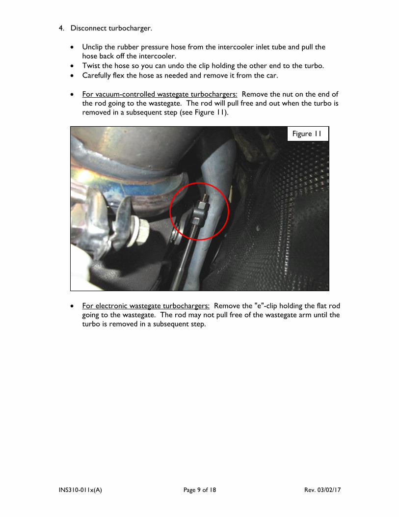
For vacuum-controlled wastegate turbochargers: Remove the nut on the end of the rod going to the wastegate. The rod will pull free and out when the turbo is
removed in a subsequent step (see Figure 11).
For electronic wastegate turbochargers: Remove the "e"-clip holding the flat rod going to the wastegate. The rod may not pull free of the wastegate arm until the
turbo is removed in a subsequent step.
Figure 11
INS310-011x(A) Page 10 of 18 Rev. 03/02/17
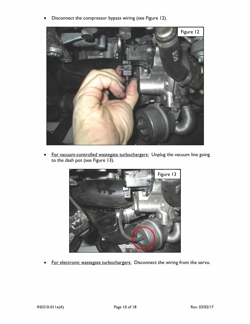
Disconnect the compressor bypass wiring (see Figure 12).
For vacuum-controlled wastegate turbochargers: Unplug the vacuum line going to the dash pot (see Figure 13).
For electronic wastegate turbochargers: Disconnect the wiring from the servo.
Figure 12
Figure 13
INS310-011x(A) Page 11 of 18 Rev. 03/02/17
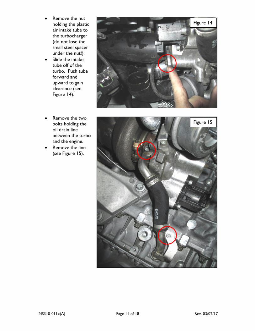
Remove the nut
holding the plastic
air intake tube to
the turbocharger (do not lose the
small steel spacer
under the nut!).
Slide the intake
tube off of the
turbo. Push tube
forward and
upward to gain
clearance (see
Figure 14).
Remove the two bolts holding the
oil drain line
between the turbo
and the engine.
Remove the line
(see Figure 15).
Figure 14
Figure 15
INS310-011x(A) Page 12 of 18 Rev. 03/02/17
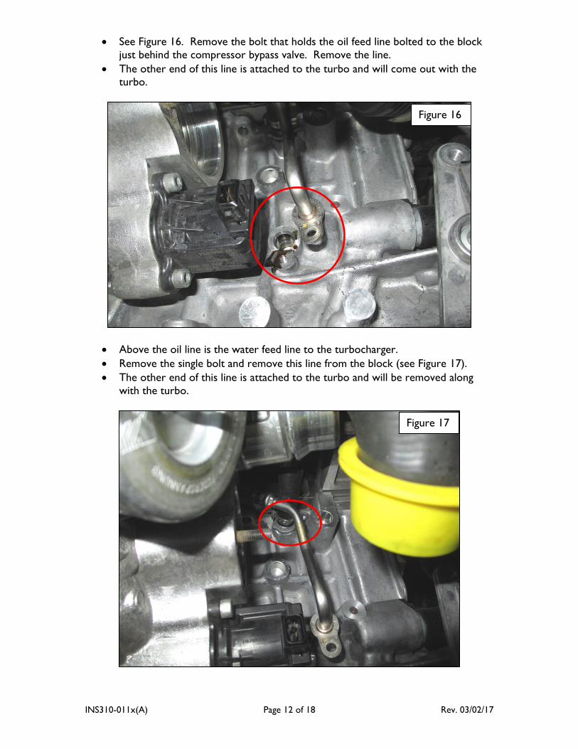
See Figure 16. Remove the bolt that holds the oil feed line bolted to the block
just behind the compressor bypass valve. Remove the line.
The other end of this line is attached to the turbo and will come out with the
turbo.
Above the oil line is the water feed line to the turbocharger.
Remove the single bolt and remove this line from the block (see Figure 17).
The other end of this line is attached to the turbo and will be removed along
with the turbo.
Figure 16
Figure 17
INS310-011x(A) Page 13 of 18 Rev. 03/02/17
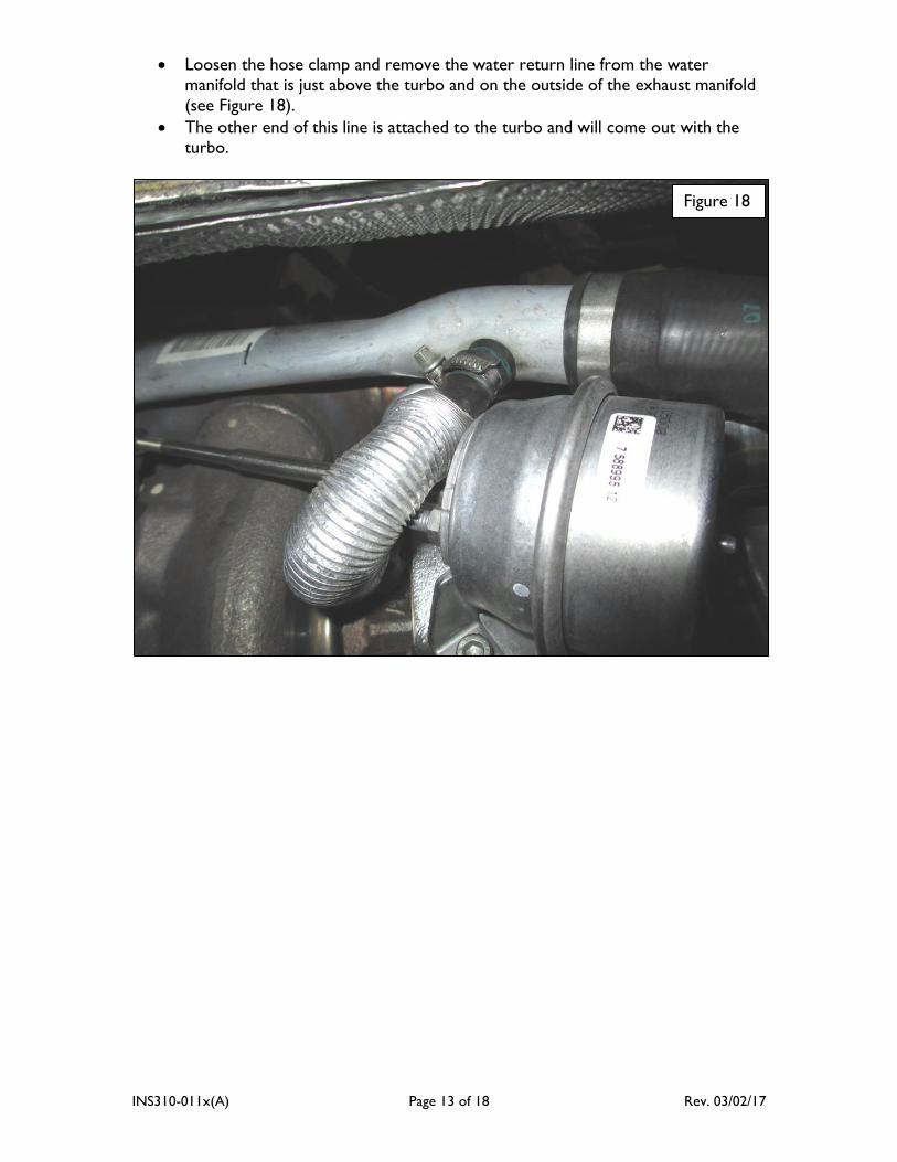
Loosen the hose clamp and remove the water return line from the water
manifold that is just above the turbo and on the outside of the exhaust manifold
(see Figure 18).
The other end of this line is attached to the turbo and will come out with the turbo.
Figure 18
INS310-011x(A) Page 14 of 18 Rev. 03/02/17
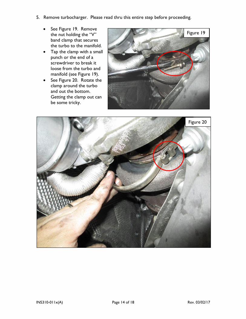
5. Remove turbocharger. Please read thru this entire step before proceeding.
See Figure 19. Remove
the nut holding the “V” band clamp that secures
the turbo to the manifold.
Tap the clamp with a small
punch or the end of a
screwdriver to break it
loose from the turbo and
manifold (see Figure 19).
See Figure 20. Rotate the clamp around the turbo
and out the bottom.
Getting the clamp out can
be some tricky.
Figure 19
Figure 20
INS310-011x(A) Page 15 of 18 Rev. 03/02/17
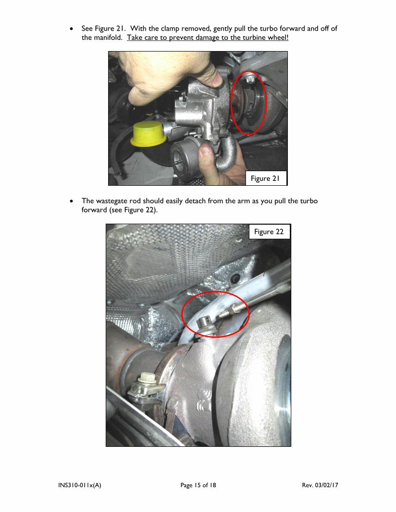
See Figure 21. With the clamp removed, gently pull the turbo forward and off of
the manifold. Take care to prevent damage to the turbine wheel!
The wastegate rod should easily detach from the arm as you pull the turbo
forward (see Figure 22).
Figure 21
Figure 22
INS310-011x(A) Page 16 of 18 Rev. 03/02/17
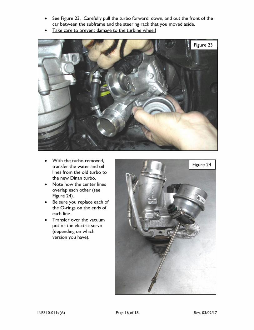
See Figure 23. Carefully pull the turbo forward, down, and out the front of the
car between the subframe and the steering rack that you moved aside.
Take care to prevent damage to the turbine wheel!
With the turbo removed,
transfer the water and oil
lines from the old turbo to
the new Dinan turbo.
Note how the center lines overlap each other (see
Figure 24).
Be sure you replace each of
the O-rings on the ends of
each line.
Transfer over the vacuum pot or the electric servo
(depending on which
version you have).
Figure 23
Figure 24
INS310-011x(A) Page 17 of 18 Rev. 03/02/17
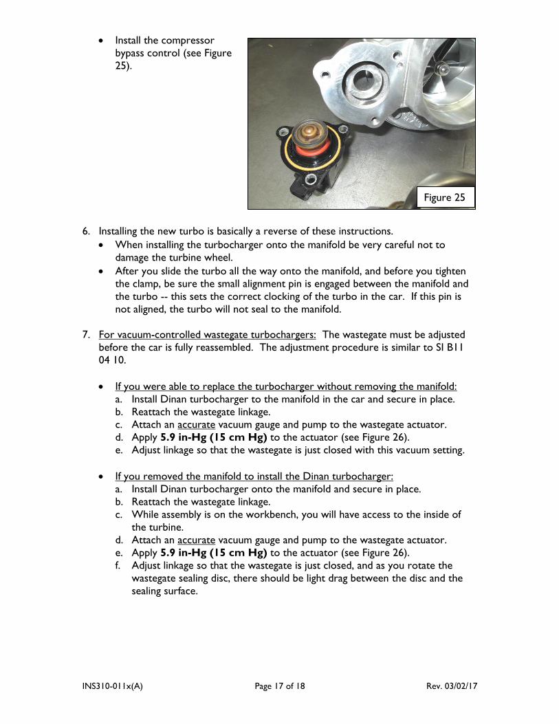
Install the compressor
bypass control (see Figure
25).
6. Installing the new turbo is basically a reverse of these instructions.
When installing the turbocharger onto the manifold be very careful not to
damage the turbine wheel.
After you slide the turbo all the way onto the manifold, and before you tighten the clamp, be sure the small alignment pin is engaged between the manifold and
the turbo -- this sets the correct clocking of the turbo in the car. If this pin is
not aligned, the turbo will not seal to the manifold.
7. For vacuum-controlled wastegate turbochargers: The wastegate must be adjusted
before the car is fully reassembled. The adjustment procedure is similar to SI B11
04 10.
If you were able to replace the turbocharger without removing the manifold:
a. Install Dinan turbocharger to the manifold in the car and secure in place.
b. Reattach the wastegate linkage. c. Attach an accurate vacuum gauge and pump to the wastegate actuator.
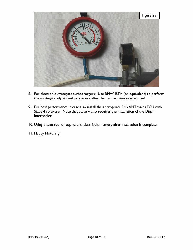
d. Apply 5.9 in-Hg (15 cm Hg) to the actuator (see Figure 26).
e. Adjust linkage so that the wastegate is just closed with this vacuum setting.
If you removed the manifold to install the Dinan turbocharger:
a. Install Dinan turbocharger onto the manifold and secure in place.
b. Reattach the wastegate linkage.
c. While assembly is on the workbench, you will have access to the inside of
the turbine.
d. Attach an accurate vacuum gauge and pump to the wastegate actuator.
e. Apply 5.9 in-Hg (15 cm Hg) to the actuator (see Figure 26).
f. Adjust linkage so that the wastegate is just closed, and as you rotate the
wastegate sealing disc, there should be light drag between the disc and the
sealing surface.
Figure 25
INS310-011x(A) Page 18 of 18 Rev. 03/02/17
8. For electronic wastegate turbochargers: Use BMW ISTA (or equivalent) to perform
the wastegate adjustment procedure after the car has been reassembled.
9. For best performance, please also install the appropriate DINANTronics ECU with
Stage 4 software. Note that Stage 4 also requires the installation of the Dinan
Intercooler.
10. Using a scan tool or equivalent, clear fault memory after installation is complete.
11. Happy Motoring!
Figure 26