Embed Size (px)
Citation preview
Donald B. Cheke www.textualcreations.ca
1
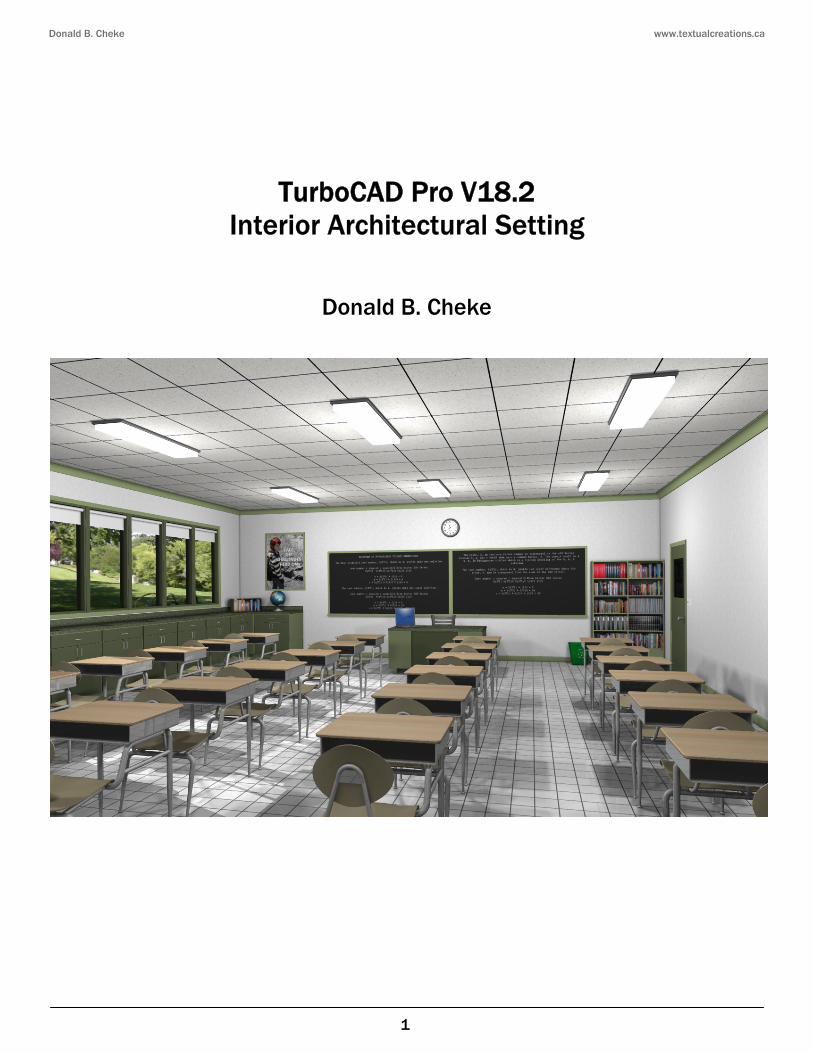
TurboCAD Pro V18.2
Interior Architectural Setting
Donald B. Cheke
Donald B. Cheke www.textualcreations.ca
2
Copyright © 2012 Donald B. Cheke TurboCAD is a registered trademark of IMSI/Design.
Published by: Donald B. Cheke Saskatoon, SK Canada Visit: www.textualcreations.ca
All rights reserved No part of this document may be reproduced, copied, stored on a retrieval system or transmitted in any form without written permission from the author. The purchaser may, however, print one copy of the document to paper and may make one backup copy of the downloaded material for personal safe keeping. Limitation of Liability While every effort has been taken in the preparation and the writing of this document the author assumes no responsibility for errors and/or omissions nor for the uses of the material and the decisions based on such use. No warranties are made, express or implied with regard to either the contents of the document, its merchant ability or fitness for a particular purpose. The author should not be liable for direct, indirect, special, incidental or consequential damages arising out of the use or inability to use the contents of this document. Special Note All of the work presented within this tutorial is based on TurboCAD Pro V18.2. Although users of previous versions are welcome to try the tutorial it cannot be stated what results will be achieved. Many changes, some subtle and others not so subtle, are made with each program revision. Although many steps and directions would be generic some may not be. The same can be said for tools between versions. Older versions may not have the same tools as Pro V18.2 and if the same tools are available the tools themselves may have been revised and hence, work in a different manner than they previously did.

Donald B. Cheke www.textualcreations.ca
3
Table of Contents Table of Contents ......................................................................................................................................................... 3 Introduction .................................................................................................................................................................. 4 Setup .............................................................................................................................................................................. 6 Floor ............................................................................................................................................................................. 24 Walls & Ceiling ........................................................................................................................................................... 25 Windows ...................................................................................................................................................................... 31 Door.............................................................................................................................................................................. 38 Wall Cabinets ............................................................................................................................................................. 46 Casings & Baseboards .............................................................................................................................................. 78 Chalkboards ................................................................................................................................................................ 91 Framed Poster ............................................................................................................................................................ 95 Bookcase ..................................................................................................................................................................... 97 Overhead Lights ...................................................................................................................................................... 107 Cornice Molding ...................................................................................................................................................... 112 Teacher's Desk ........................................................................................................................................................ 117 Clock ......................................................................................................................................................................... 122 Window Blinds ......................................................................................................................................................... 126 Globe ......................................................................................................................................................................... 132 Door Knob ................................................................................................................................................................ 142 Additional Supplied Components ......................................................................................................................... 145 Materials Application ............................................................................................................................................. 155 Named View ............................................................................................................................................................. 212 Render Scene Luminance ..................................................................................................................................... 218 Render Scene Environment .................................................................................................................................. 224 Saving the Rendered Image.................................................................................................................................. 227
Donald B. Cheke www.textualcreations.ca
4
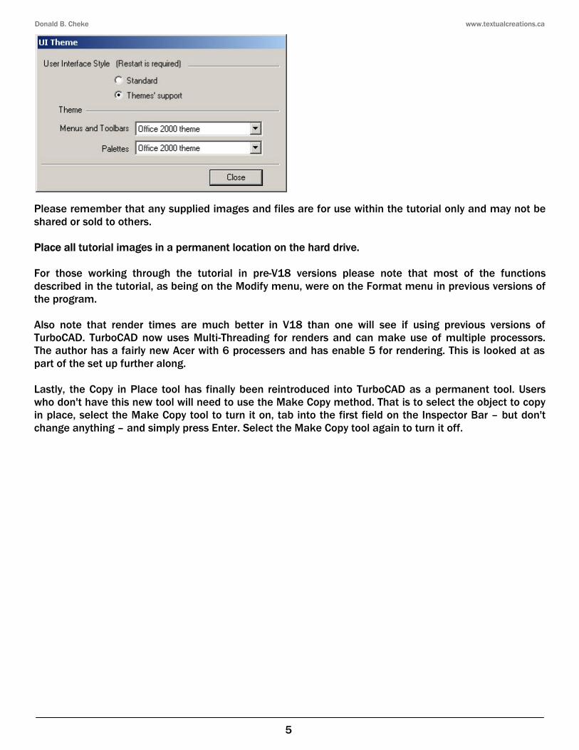
Introduction A common request for theme specific TurboCAD tutorials is interior architectural renderings. Those that have submitted requests often include the desire to learn how to approach such a theme, how to use an image to reflect what is visible outside the windows and how to establish interior and exterior lighting that will help make the scene seem welcoming and believable. It is with this in mind that TurboCAD V18.2 Pro - Interior Architectural Setting has been created. Within the tutorial the reader will be led through each keystroke to produce most of components of the classroom that are illustrated on the cover of the tutorial. Five items are supplied to help keep the tutorial time to a manageable amount. Supplied models include the Laptop, the Light Switches, the Recycle Bin, the Teacher's Chair and the Student Desk. Aside from learning how to draw in TurboCAD, the user will learn how to set up the drawing and how to insert standard lighting. The reader will learn how to establish render scene luminance and a render scene environment. The reader will also learn how to render their drawing and save it in a high resolution image format. This tutorial is in no way intended to teach the fundamentals of architectural design or construction but rather it is intended to teach the use of some of the tools that TurboCAD has to offer and to introduce the new user to a drawing methodology. The author feels confident that the techniques outlined within the tutorial can help lay the foundation for future successful TurboCAD drawing and illustration for even the newest user. As with any technically advanced software, the user is generally faced with a steep learning curve. It is the hope of the author that the money and time spent working through a Textual Creations tutorial will help ease the learning and allow the reader to come away feeling confident that they made a wise decision. This tutorial will assume that the reader has the Platinum Edition of TurboCAD Pro 18.2 with its extra architectural and mechanical tools. Although no mechanical specific tools are used that the author is aware of, some architectural specific tools are (parametric cabinet which may be Platinum specific). There are many ways to approach a project and it is likely that each person using the program would proceed in very different ways, so be open to alternative methods as experience builds. What is important is that the user becomes familiar with the objects that they wish to model and begin to look at them in a different way than they might otherwise do. What primitive shapes make up the whole? What will be required of these primitive shapes early in the drawing and how will this affect needs further along? What component or components should be started with? Many questions can only be answered through experience, but hopefully some of them will be answered by the time the beginner has worked through this tutorial. There is a great deal covered in this tutorial and the author urges the beginner to be patient, to read very carefully and to take the time necessary to do a good job. Try to enjoy the process as much as you will enjoy the final results. This tutorial assumes that the beginner has studied the desktop to some degree and can locate most of the tools. Since there are endless desktop configurations that can be set up in TurboCAD the author has opted to illustrate the required tools with the Office 2000 user interface, and the default toolbars in their undocked format (Office 2000 theme).
Donald B. Cheke www.textualcreations.ca
5
Please remember that any supplied images and files are for use within the tutorial only and may not be shared or sold to others. Place all tutorial images in a permanent location on the hard drive. For those working through the tutorial in pre-V18 versions please note that most of the functions described in the tutorial, as being on the Modify menu, were on the Format menu in previous versions of the program. Also note that render times are much better in V18 than one will see if using previous versions of TurboCAD. TurboCAD now uses Multi-Threading for renders and can make use of multiple processors. The author has a fairly new Acer with 6 processers and has enable 5 for rendering. This is looked at as part of the set up further along. Lastly, the Copy in Place tool has finally been reintroduced into TurboCAD as a permanent tool. Users who don't have this new tool will need to use the Make Copy method. That is to select the object to copy in place, select the Make Copy tool to turn it on, tab into the first field on the Inspector Bar – but don't change anything – and simply press Enter. Select the Make Copy tool again to turn it off.
Donald B. Cheke www.textualcreations.ca
27
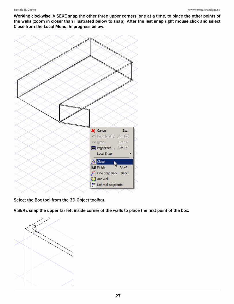
Working clockwise, V SEKE snap the other three upper corners, one at a time, to place the other points of the walls (zoom in closer than illustrated below to snap). After the last snap right mouse click and select Close from the Local Menu. In progress below.
Select the Box tool from the 3D Object toolbar. V SEKE snap the upper far left inside corner of the walls to place the first point of the box.
Donald B. Cheke www.textualcreations.ca
32
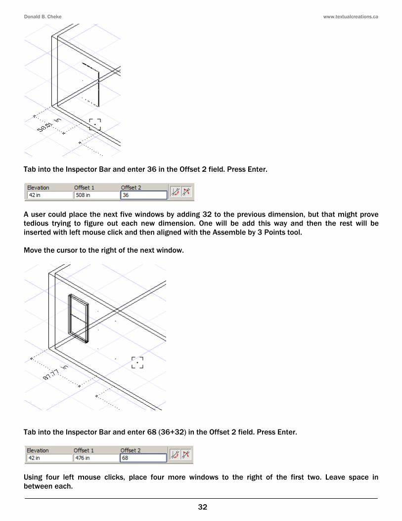
Tab into the Inspector Bar and enter 36 in the Offset 2 field. Press Enter.
A user could place the next five windows by adding 32 to the previous dimension, but that might prove tedious trying to figure out each new dimension. One will be add this way and then the rest will be inserted with left mouse click and then aligned with the Assemble by 3 Points tool. Move the cursor to the right of the next window.
Tab into the Inspector Bar and enter 68 (36+32) in the Offset 2 field. Press Enter.
Using four left mouse clicks, place four more windows to the right of the first two. Leave space in between each.
Donald B. Cheke www.textualcreations.ca
44
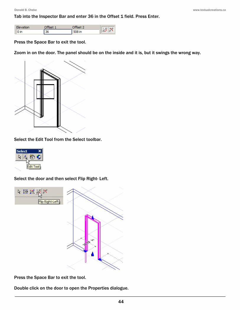
Tab into the Inspector Bar and enter 36 in the Offset 1 field. Press Enter.
Press the Space Bar to exit the tool. Zoom in on the door. The panel should be on the inside and it is, but it swings the wrong way.
Select the Edit Tool from the Select toolbar.
Select the door and then select Flip Right- Left.
Press the Space Bar to exit the tool. Double click on the door to open the Properties dialogue.
Donald B. Cheke www.textualcreations.ca
73
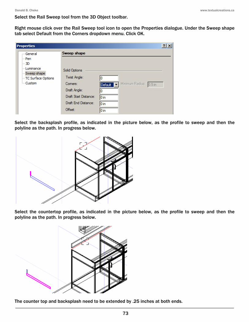
Select the Rail Sweep tool from the 3D Object toolbar. Right mouse click over the Rail Sweep tool icon to open the Properties dialogue. Under the Sweep shape tab select Default from the Corners dropdown menu. Click OK.
Select the backsplash profile, as indicated in the picture below, as the profile to sweep and then the polyline as the path. In progress below.
Select the countertop profile, as indicated in the picture below, as the profile to sweep and then the polyline as the path. In progress below.
The counter top and backsplash need to be extended by .25 inches at both ends.
Donald B. Cheke
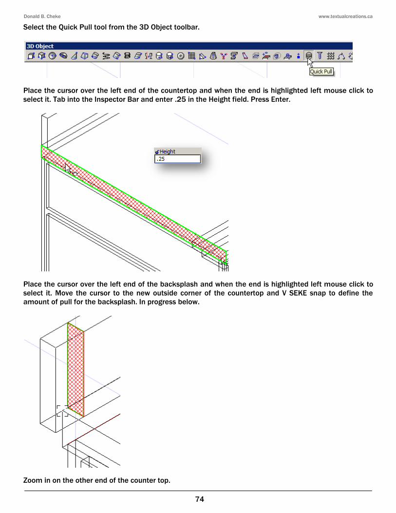
Select the Quick Pull tool from the 3D Object toolbar.
Place the cursor over the left end of the countertop and select it. Tab into the Inspector Bar and enter
Place the cursor over the left end of the backsplash and when the end is highlighted select it. Move the cursor to the new outside corner of the countertop and V SEKE snap to define the amount of pull for the backsplash. In progress below.
Zoom in on the other end of the counter top.
Donald B. Cheke
74
Select the Quick Pull tool from the 3D Object toolbar.
Place the cursor over the left end of the countertop and when the end is highlightedTab into the Inspector Bar and enter .25 in the Height field. Press Enter.
Place the cursor over the left end of the backsplash and when the end is highlighted Move the cursor to the new outside corner of the countertop and V SEKE snap to define the
In progress below.
Zoom in on the other end of the counter top.
www.textualcreations.ca
when the end is highlighted left mouse click to
Place the cursor over the left end of the backsplash and when the end is highlighted left mouse click to Move the cursor to the new outside corner of the countertop and V SEKE snap to define the
Donald B. Cheke
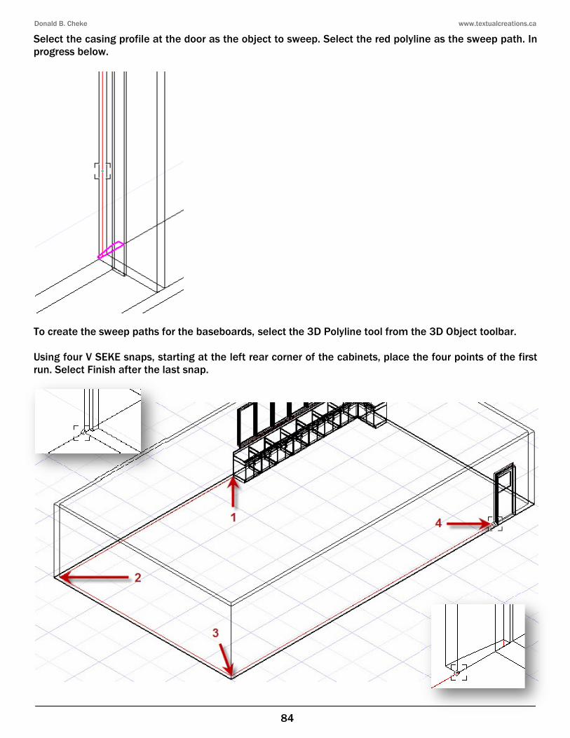
Select the casing profile at the door as the object to sweep. Select the progress below.
To create the sweep paths for the baseboards, Using four V SEKE snaps, starting at the left rear corner of the cabinets,run. Select Finish after the last snap.
Donald B. Cheke
84
as the object to sweep. Select the red polyline
To create the sweep paths for the baseboards, select the 3D Polyline tool from the 3D O
, starting at the left rear corner of the cabinets, place the four points of the first
www.textualcreations.ca
polyline as the sweep path. In
select the 3D Polyline tool from the 3D Object toolbar.
place the four points of the first
Donald B. Cheke
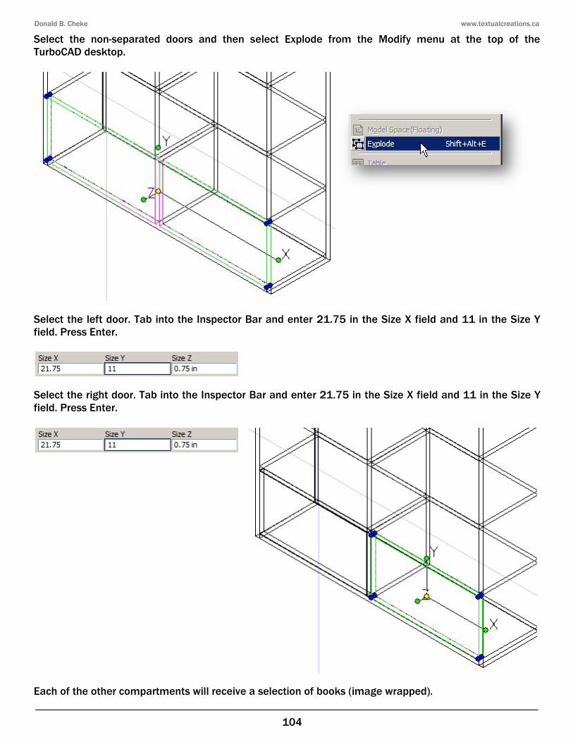
Select the non-separated doors and then sTurboCAD desktop.
Select the left door. Tab into the Inspector Bar and enterfield. Press Enter.
Select the right door. Tab into the Inspector Bar and enterfield. Press Enter.
Each of the other compartments will receive a selection of books (image wrapped).
Donald B. Cheke
104
separated doors and then select Explode from the Modify menu at the t
Tab into the Inspector Bar and enter 21.75 in the Size X field and 11 in the Size Y
Tab into the Inspector Bar and enter 21.75 in the Size X field and 11 in the Size Y
Each of the other compartments will receive a selection of books (image wrapped).
www.textualcreations.ca
from the Modify menu at the top of the
21.75 in the Size X field and 11 in the Size Y
21.75 in the Size X field and 11 in the Size Y
Each of the other compartments will receive a selection of books (image wrapped).
Donald B. Cheke www.textualcreations.ca
112
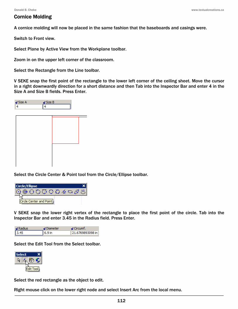
Cornice Molding A cornice molding will now be placed in the same fashion that the baseboards and casings were. Switch to Front view. Select Plane by Active View from the Workplane toolbar. Zoom in on the upper left corner of the classroom. Select the Rectangle from the Line toolbar. V SEKE snap the first point of the rectangle to the lower left corner of the ceiling sheet. Move the cursor in a right downwardly direction for a short distance and then Tab into the Inspector Bar and enter 4 in the Size A and Size B fields. Press Enter.
Select the Circle Center & Point tool from the Circle/Ellipse toolbar.
V SEKE snap the lower right vertex of the rectangle to place the first point of the circle. Tab into the Inspector Bar and enter 3.45 in the Radius field. Press Enter.
Select the Edit Tool from the Select toolbar.
Select the red rectangle as the object to edit. Right mouse click on the lower right node and select Insert Arc from the local menu.
Donald B. Cheke www.textualcreations.ca
121
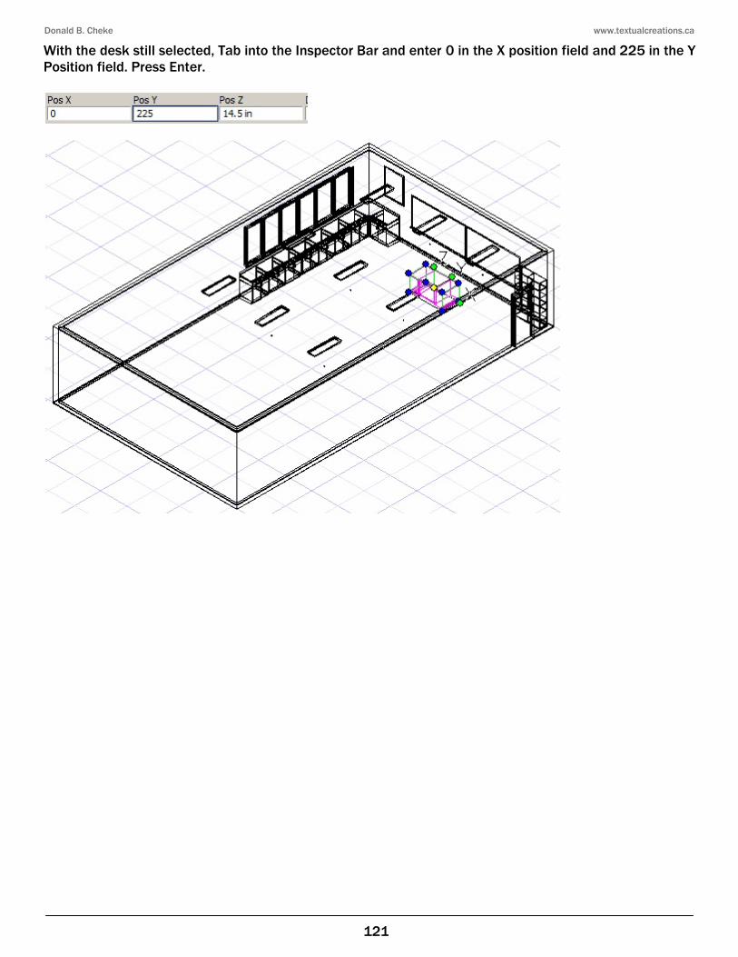
With the desk still selected, Tab into the Inspector Bar and enter 0 in the X position field and 225 in the Y Position field. Press Enter.
Donald B. Cheke www.textualcreations.ca
133
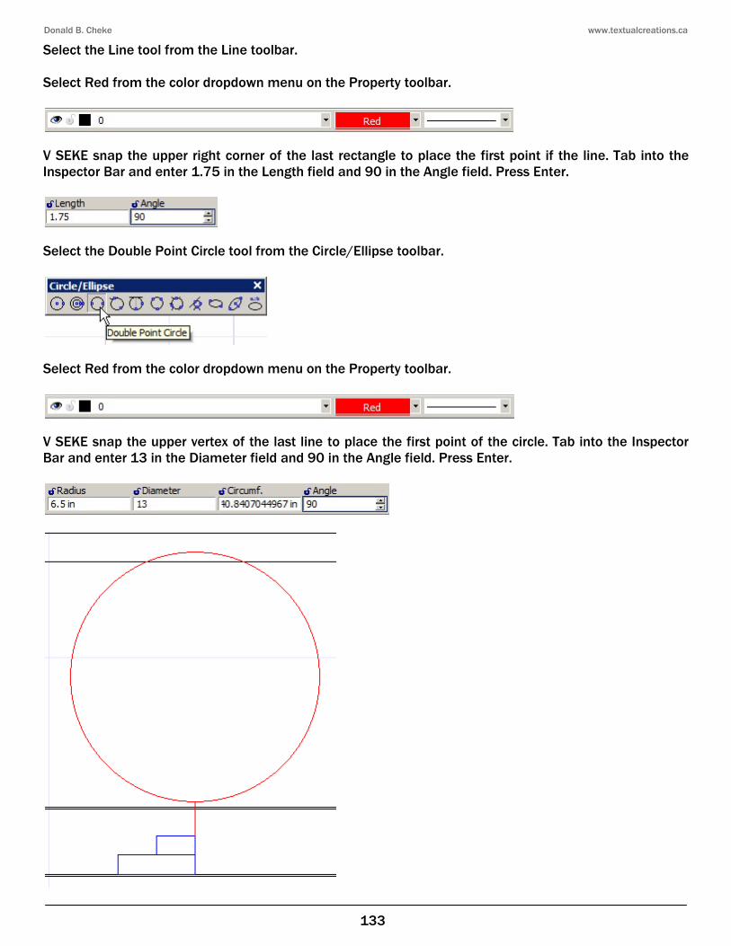
Select the Line tool from the Line toolbar. Select Red from the color dropdown menu on the Property toolbar.
V SEKE snap the upper right corner of the last rectangle to place the first point if the line. Tab into the Inspector Bar and enter 1.75 in the Length field and 90 in the Angle field. Press Enter.
Select the Double Point Circle tool from the Circle/Ellipse toolbar.
Select Red from the color dropdown menu on the Property toolbar.
V SEKE snap the upper vertex of the last line to place the first point of the circle. Tab into the Inspector Bar and enter 13 in the Diameter field and 90 in the Angle field. Press Enter.
Donald B. Cheke www.textualcreations.ca
134
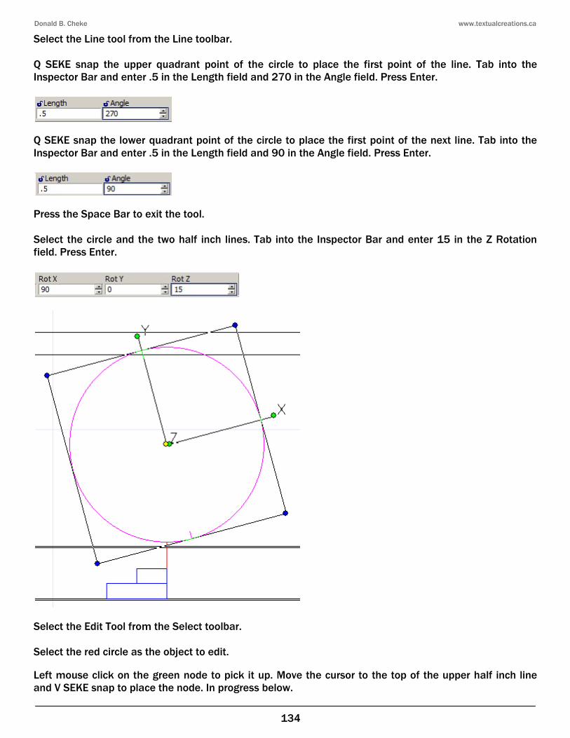
Select the Line tool from the Line toolbar. Q SEKE snap the upper quadrant point of the circle to place the first point of the line. Tab into the Inspector Bar and enter .5 in the Length field and 270 in the Angle field. Press Enter.
Q SEKE snap the lower quadrant point of the circle to place the first point of the next line. Tab into the Inspector Bar and enter .5 in the Length field and 90 in the Angle field. Press Enter.
Press the Space Bar to exit the tool. Select the circle and the two half inch lines. Tab into the Inspector Bar and enter 15 in the Z Rotation field. Press Enter.
Select the Edit Tool from the Select toolbar. Select the red circle as the object to edit. Left mouse click on the green node to pick it up. Move the cursor to the top of the upper half inch line and V SEKE snap to place the node. In progress below.
Donald B. Cheke www.textualcreations.ca
145
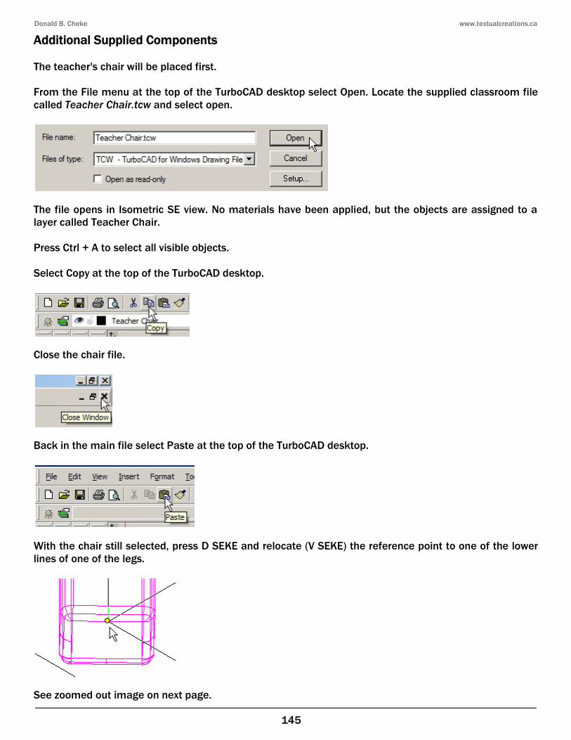
Additional Supplied Components The teacher's chair will be placed first. From the File menu at the top of the TurboCAD desktop select Open. Locate the supplied classroom file called Teacher Chair.tcw and select open.
The file opens in Isometric SE view. No materials have been applied, but the objects are assigned to a layer called Teacher Chair. Press Ctrl + A to select all visible objects. Select Copy at the top of the TurboCAD desktop.
Close the chair file.
Back in the main file select Paste at the top of the TurboCAD desktop.
With the chair still selected, press D SEKE and relocate (V SEKE) the reference point to one of the lower lines of one of the legs.
See zoomed out image on next page.
Donald B. Cheke www.textualcreations.ca
170
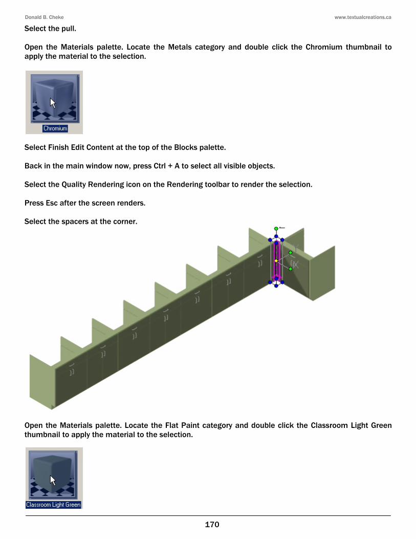
Select the pull. Open the Materials palette. Locate the Metals category and double click the Chromium thumbnail to apply the material to the selection.
Select Finish Edit Content at the top of the Blocks palette. Back in the main window now, press Ctrl + A to select all visible objects. Select the Quality Rendering icon on the Rendering toolbar to render the selection. Press Esc after the screen renders. Select the spacers at the corner.
Open the Materials palette. Locate the Flat Paint category and double click the Classroom Light Green thumbnail to apply the material to the selection.
Donald B. Cheke www.textualcreations.ca
171
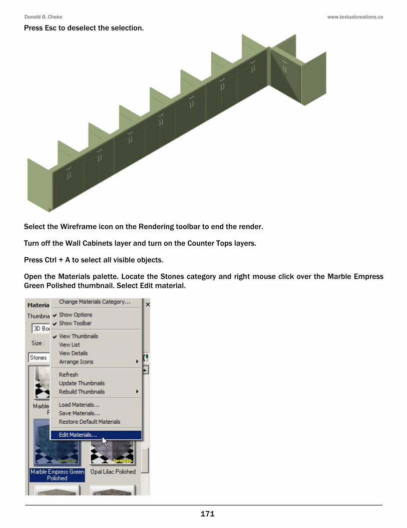
Press Esc to deselect the selection.
Select the Wireframe icon on the Rendering toolbar to end the render. Turn off the Wall Cabinets layer and turn on the Counter Tops layers. Press Ctrl + A to select all visible objects. Open the Materials palette. Locate the Stones category and right mouse click over the Marble Empress Green Polished thumbnail. Select Edit material.
Donald B. Cheke www.textualcreations.ca
179
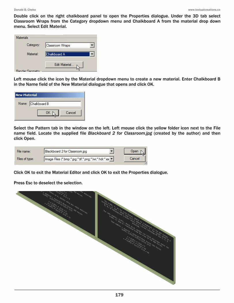
Double click on the right chalkboard panel to open the Properties dialogue. Under the 3D tab select Classroom Wraps from the Category dropdown menu and Chalkboard A from the material drop down menu. Select Edit Material.
Left mouse click the icon by the Material dropdown menu to create a new material. Enter Chalkboard B in the Name field of the New Material dialogue that opens and click OK.
Select the Pattern tab in the window on the left. Left mouse click the yellow folder icon next to the File name field. Locate the supplied file Blackboard 2 for Classroom.jpg (created by the author) and then click Open.
Click OK to exit the Material Editor and click OK to exit the Properties dialogue. Press Esc to deselect the selection.
Donald B. Cheke www.textualcreations.ca
189
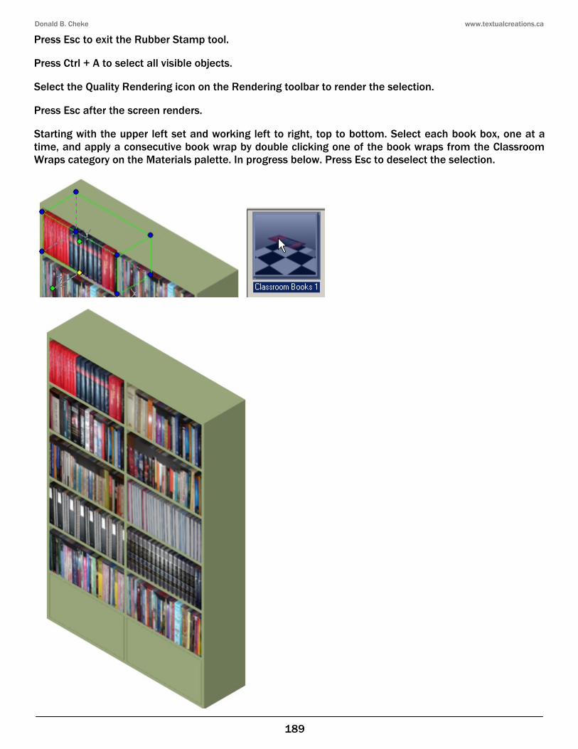
Press Esc to exit the Rubber Stamp tool. Press Ctrl + A to select all visible objects. Select the Quality Rendering icon on the Rendering toolbar to render the selection. Press Esc after the screen renders. Starting with the upper left set and working left to right, top to bottom. Select each book box, one at a time, and apply a consecutive book wrap by double clicking one of the book wraps from the Classroom Wraps category on the Materials palette. In progress below. Press Esc to deselect the selection.
Donald B. Cheke www.textualcreations.ca
199
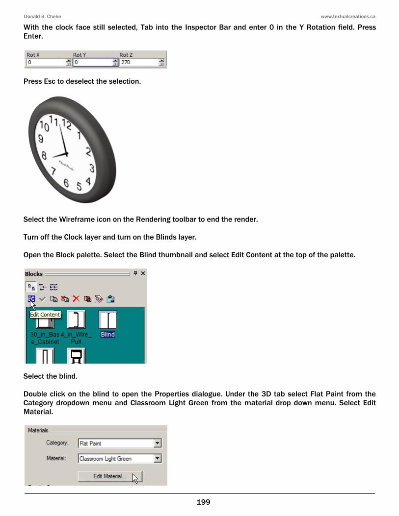
With the clock face still selected, Tab into the Inspector Bar and enter 0 in the Y Rotation field. Press Enter.
Press Esc to deselect the selection.
Select the Wireframe icon on the Rendering toolbar to end the render. Turn off the Clock layer and turn on the Blinds layer. Open the Block palette. Select the Blind thumbnail and select Edit Content at the top of the palette.
Select the blind. Double click on the blind to open the Properties dialogue. Under the 3D tab select Flat Paint from the Category dropdown menu and Classroom Light Green from the material drop down menu. Select Edit Material.
Donald B. Cheke www.textualcreations.ca
204
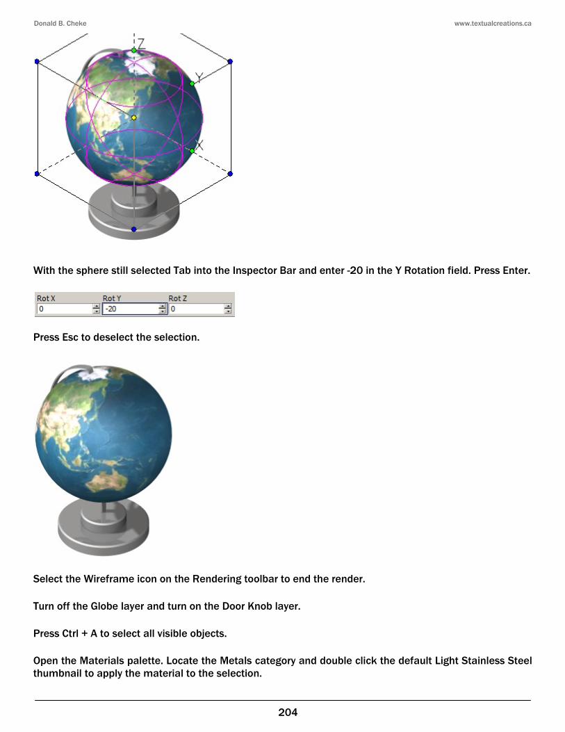
With the sphere still selected Tab into the Inspector Bar and enter -20 in the Y Rotation field. Press Enter.
Press Esc to deselect the selection.
Select the Wireframe icon on the Rendering toolbar to end the render. Turn off the Globe layer and turn on the Door Knob layer. Press Ctrl + A to select all visible objects. Open the Materials palette. Locate the Metals category and double click the default Light Stainless Steel thumbnail to apply the material to the selection.
Donald B. Cheke www.textualcreations.ca
213
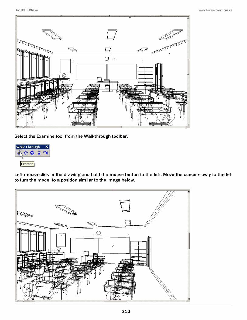
Select the Examine tool from the Walkthrough toolbar.
Left mouse click in the drawing and hold the mouse button to the left. Move the cursor slowly to the left to turn the model to a position similar to the image below.
Donald B. Cheke www.textualcreations.ca
226
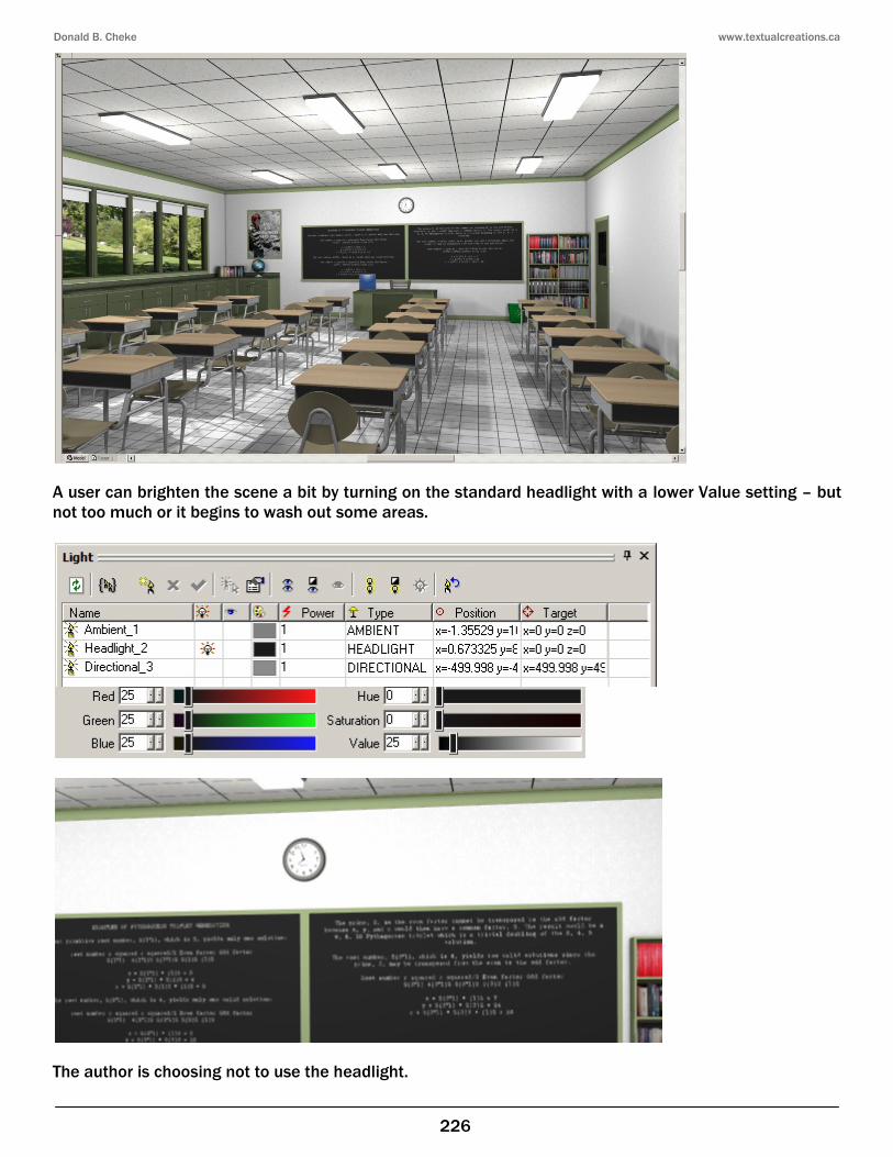
A user can brighten the scene a bit by turning on the standard headlight with a lower Value setting – but not too much or it begins to wash out some areas.
The author is choosing not to use the headlight.