Embed Size (px)
Citation preview
Turbo-Expander CompressorActive Magnetic Bearing
Trips Reduction - A Case Study
Chong Ong RasGas Jim Cencula GE O&GRandy Wu GE O&GMarcin Bielecki GE O&G/ EDCMatthias Lelanno S2M
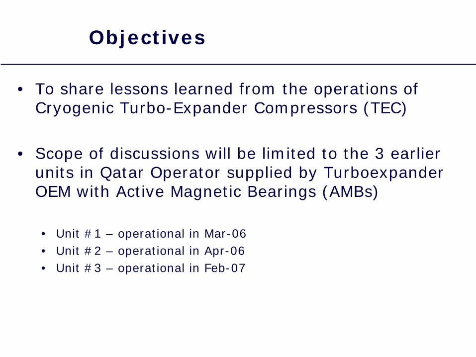
Objectives
• To share lessons learned from the operations of Cryogenic Turbo-Expander Compressors (TEC)
• Scope of discussions will be limited to the 3 earlier units in Qatar Operator supplied by Turboexpander OEM with Active Magnetic Bearings (AMBs)
• Unit #1 – operational in Mar-06• Unit #2 – operational in Apr-06• Unit #3 – operational in Feb-07
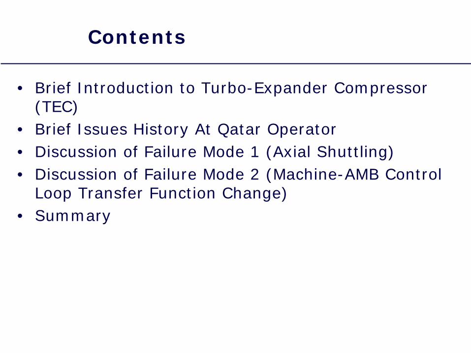
Contents
• Brief Introduction to Turbo-Expander Compressor (TEC)
• Brief Issues History At Qatar Operator• Discussion of Failure Mode 1 (Axial Shuttling)• Discussion of Failure Mode 2 (Machine-AMB Control
Loop Transfer Function Change)• Summary
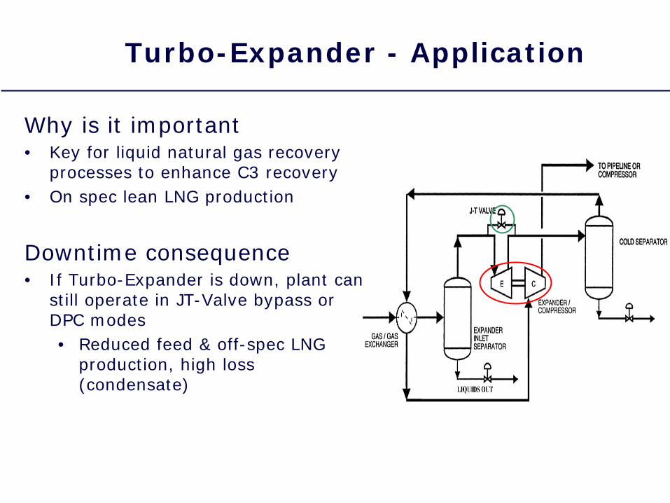
Turbo-Expander - Application
Why is it important• Key for liquid natural gas recovery
processes to enhance C3 recovery• On spec lean LNG production
Downtime consequence• If Turbo-Expander is down, plant can
still operate in JT-Valve bypass or DPC modes• Reduced feed & off-spec LNG
production, high loss (condensate)
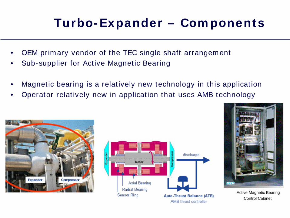
Active Magnetic BearingControl Cabinet
Turbo-Expander – Components
• OEM primary vendor of the TEC single shaft arrangement• Sub-supplier for Active Magnetic Bearing
• Magnetic bearing is a relatively new technology in this application• Operator relatively new in application that uses AMB technology
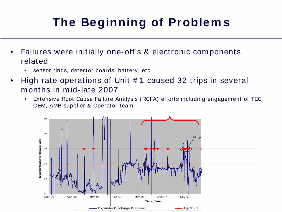
The Beginning of Problems
• Failures were initially one-off’s & electronic components related• sensor rings, detector boards, battery, etc
• High rate operations of Unit #1 caused 32 trips in several months in mid-late 2007• Extensive Root Cause Failure Analysis (RCFA) efforts including engagement of TEC
OEM, AMB supplier & Operator team
21
22
23
24
25
26
May-06 Aug-06 Nov-06 Feb-07 May-07 Aug-07 Nov-07
Tim e, Date
Expa
nder
Dis
char
ge P
ress
ure,
Bar
g
Expander Discharge Pressure Trip Point
15 trips
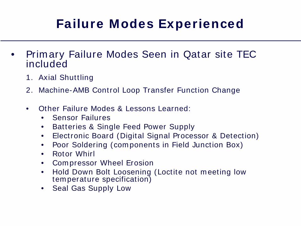
Failure Modes Experienced
• Primary Failure Modes Seen in Qatar site TEC included1. Axial Shuttling
2. Machine-AMB Control Loop Transfer Function Change
• Other Failure Modes & Lessons Learned:• Sensor Failures• Batteries & Single Feed Power Supply• Electronic Board (Digital Signal Processor & Detection)• Poor Soldering (components in Field Junction Box)• Rotor Whirl• Compressor Wheel Erosion• Hold Down Bolt Loosening (Loctite not meeting low
temperature specification)• Seal Gas Supply Low
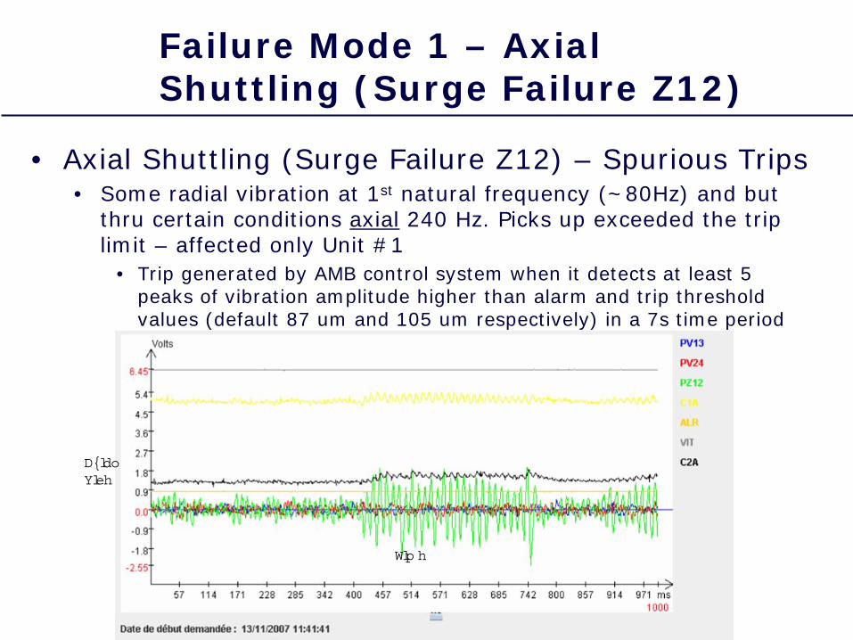
Failure Mode 1 – Axial Shuttling (Surge Failure Z12)
• Axial Shuttling (Surge Failure Z12) – Spurious Trips• Some radial vibration at 1st natural frequency (~80Hz) and but
thru certain conditions axial 240 Hz. Picks up exceeded the trip limit – affected only Unit #1
• Trip generated by AMB control system when it detects at least 5 peaks of vibration amplitude higher than alarm and trip threshold values (default 87 um and 105 um respectively) in a 7s time period
Tim e
AxialVibe
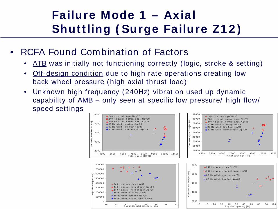
Failure Mode 1 – Axial Shuttling (Surge Failure Z12)
• RCFA Found Combination of Factors• ATB was initially not functioning correctly (logic, stroke & setting)• Off-design condition due to high rate operations creating low
back wheel pressure (high axial thrust load)• Unknown high frequency (240Hz) vibration used up dynamic
capability of AMB – only seen at specific low pressure/ high flow/ speed settings
1 6 0 0 0
1 8 0 0 0
2 0 0 0 0
2 2 0 0 0
2 4 0 0 0
2 6 0 0 0
2 8 0 0 0
3 0 0 0 0
3 2 0 0 0
4 5 0 0 5 5 0 0 6 5 0 0 7 5 0 0 8 5 0 0 9 5 0 0 1 0 5 0 0 1 1 5 0 0R o to r s p e e d [R P M ]
Com
pres
sor i
nlet
flow
[AC
FM]
.
2 4 0 H z a x ia l - t rip s N o v'0 72 4 0 H z a x ia l - n o rm a l o p e r. N o v'0 92 4 0 H z a x ia l - n o rm a l o p e r. A p r'0 98 0 H z w h irl - s ta rt -u p Ja n '0 98 0 H z w h irl - lo w flo w N o v'0 98 0 H z w h irl - n o rm a l o p e r. A p r'0 9
2 0 0 0
3 0 0 0
4 0 0 0
5 0 0 0
6 0 0 0
4 5 0 0 5 5 0 0 6 5 0 0 7 5 0 0 8 5 0 0 9 5 0 0 1 0 5 0 0 1 1 5 0 0R o to r s p e e d [R P M ]
Exp
ande
r inl
et fl
ow [A
CFM
] .
2 4 0 H z a x ia l - t rip s N o v'0 72 4 0 H z a x ia l - n o rm a l o p e r. N o v'0 92 4 0 H z a x ia l - n o rm a l o p e r. A p r'0 98 0 H z w h irl - s ta rt -u p Ja n '0 98 0 H z w h irl - lo w flo w N o v'0 98 0 H z w h irl - n o rm a l o p e r. A p r'0 9
2 0 0 0
3 0 0 0
4 0 0 0
5 0 0 0
6 0 0 0
0 1 0 2 0 3 0 4 0 5 0 6 0 7 0 8 0 9 0 1 0 0E x p IG V o p e n in g [% ]
Exp
ande
r inl
et fl
ow [A
CFM
] .
2 4 0 H z a x ia l - t rip s N o v'0 7
2 4 0 H z a x ia l - n o rm a l o p e r. N o v'0 9
8 0 H z w h irl - s ta rt -u p Ja n '0 9
8 0 H z w h irl - lo w flo w N o v'0 9
0
1 0 0 0 0 0
2 0 0 0 0 0
3 0 0 0 0 0
4 0 0 0 0 0
5 0 0 0 0 0
6 0 0 0 0 0
7 0 0 0 0 0
8 0 0 0 0 0
6 0 6 1 6 2 6 3 6 4 6 5 6 6 6 7E x p a n d e r in le t p re s s u re [b a rg ]
Expa
nder
flow
[Nm
^3/h
r] .
2 4 0 H z a x ia l - t rip s N o v'0 72 4 0 H z a x ia l - n o rm a l o p e r. N o v'0 92 4 0 H z a x ia l - n o rm a l o p e r. A p r'0 98 0 H z w h irl - s ta rt -u p Ja n '0 98 0 H z w h irl - lo w flo w N o v'0 98 0 H z w h irl - n o rm a l o p e r. A p r'0 9
RCA Work/ CA Completed
• Automatic Thrust Balance logic, stroke & setting corrected
• Increased Thrust Bias Current (12A –> 15A) to improve Dynamic Capability of AMB (by 60%)
• Better thrust balance after change of TEC Machine Center Section in Jan. 2009
• Stability check performed unloaded/ 50% neg. stiffness
• Extensive review confirmed ATB design (valve and piping), but measured pressure drop higher than expected
• Rotor dynamic analysis confirmed 80Hz natural frequency … but could not detect any 240Hz cross- coupling
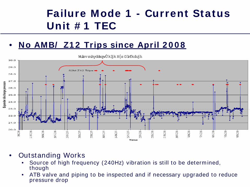
Failure Mode 1 - Current Status Unit #1 TEC
• No AMB/ Z12 Trips since April 2008
• Outstanding Works• Source of high frequency (240Hz) vibration is still to be determined,
though• ATB valve and piping to be inspected and if necessary upgraded to reduce
pressure drop
Trips prevalent –high Exp Discharge
Failure Mode 2 – Transfer Function Changed
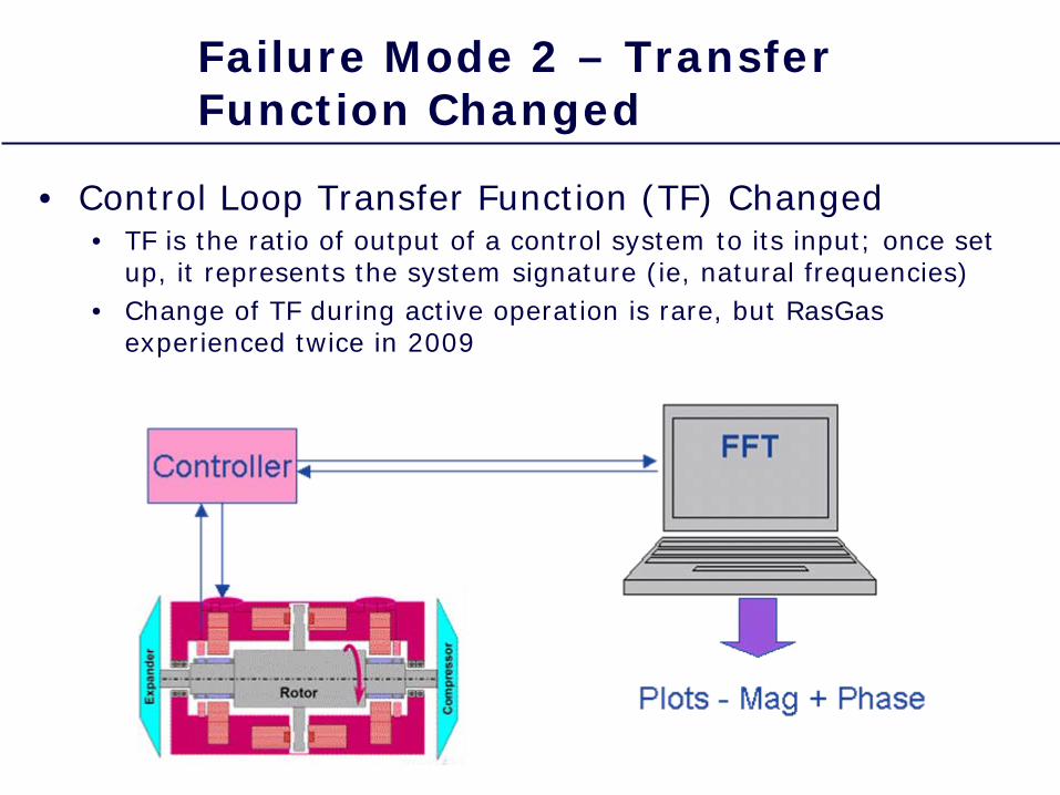
• Control Loop Transfer Function (TF) Changed• TF is the ratio of output of a control system to its input; once set
up, it represents the system signature (ie, natural frequencies)• Change of TF during active operation is rare, but RasGas
experienced twice in 2009
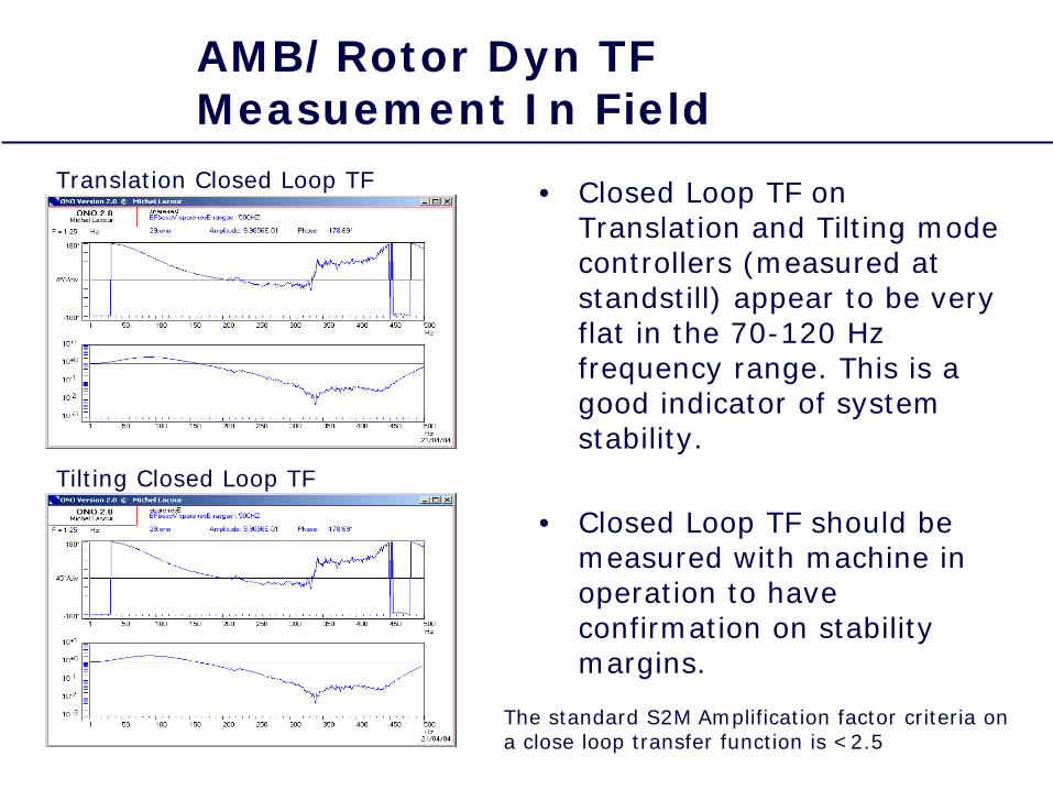
• Closed Loop TF on Translation and Tilting mode controllers (measured at standstill) appear to be very flat in the 70-120 Hz frequency range. This is a good indicator of system stability.
• Closed Loop TF should be measured with machine in operation to have confirmation on stability margins.
Translation Closed Loop TF
Tilting Closed Loop TF
The standard S2M Amplification factor criteria on a close loop transfer function is <2.5
AMB/Rotor Dyn TF Measuement In Field
Failure Mode 2 – Transfer Function Changed
• High frequency TF change in Unit #1 unit (Figures A1-A3)• Mitigated by software modification • Machine operational, but fault unknown
• Low frequency change in Units #2 & #3 unit (Figure B1)• Cannot restart, reinstall old unit• Severe rubs of stator and rotor (photos)• Root cause identified
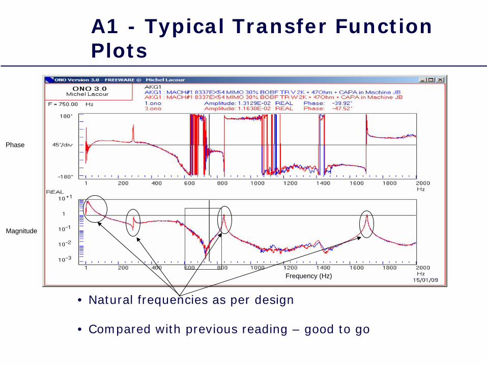
• Natural frequencies as per design
• Compared with previous reading – good to go
Frequency (Hz)
Magnitude
Phase
A1 - Typical Transfer Function Plots
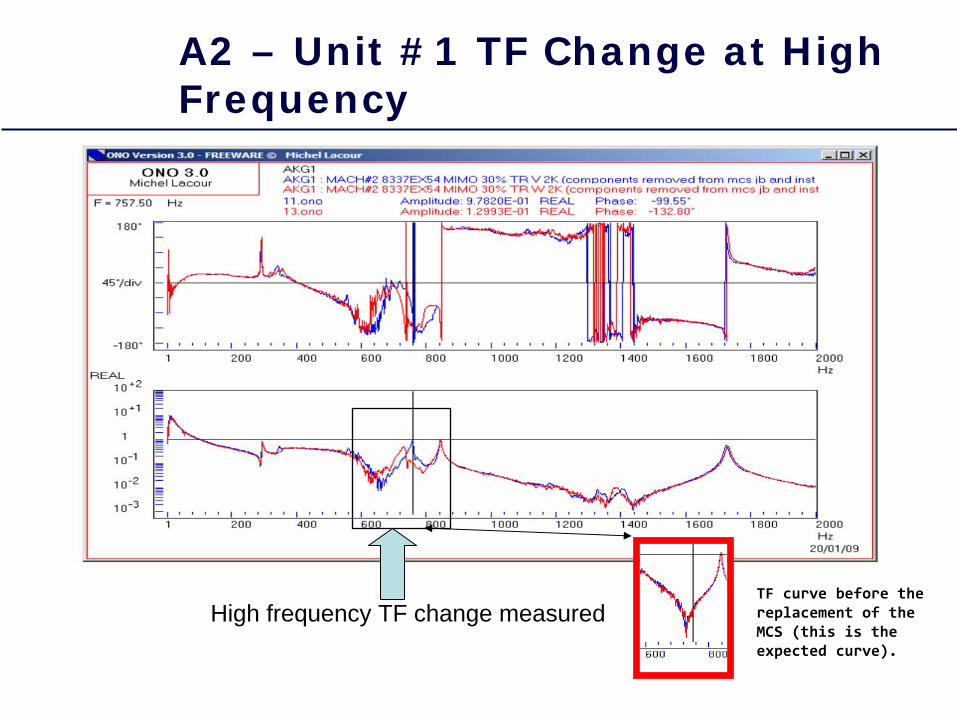
High frequency TF change measured TF curve before the
replacement of the
MCS (this is the
expected curve).
A2 – Unit #1 TF Change at High Frequency
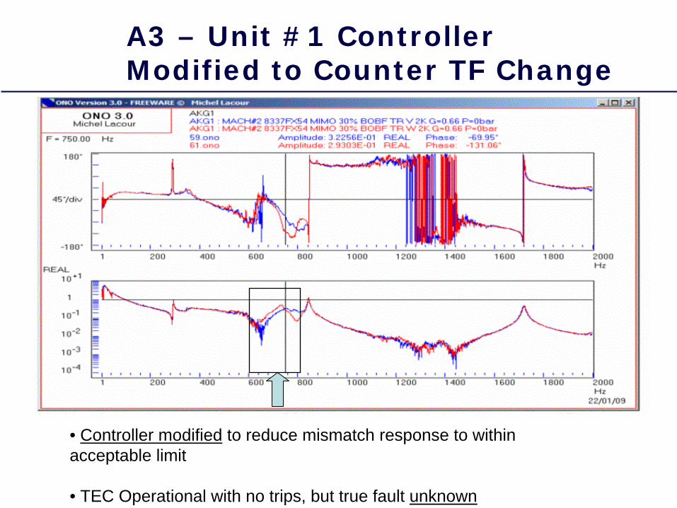
• Controller modified to reduce mismatch response to within acceptable limit
• TEC Operational with no trips, but true fault unknown
A3 – Unit #1 Controller Modified to Counter TF Change
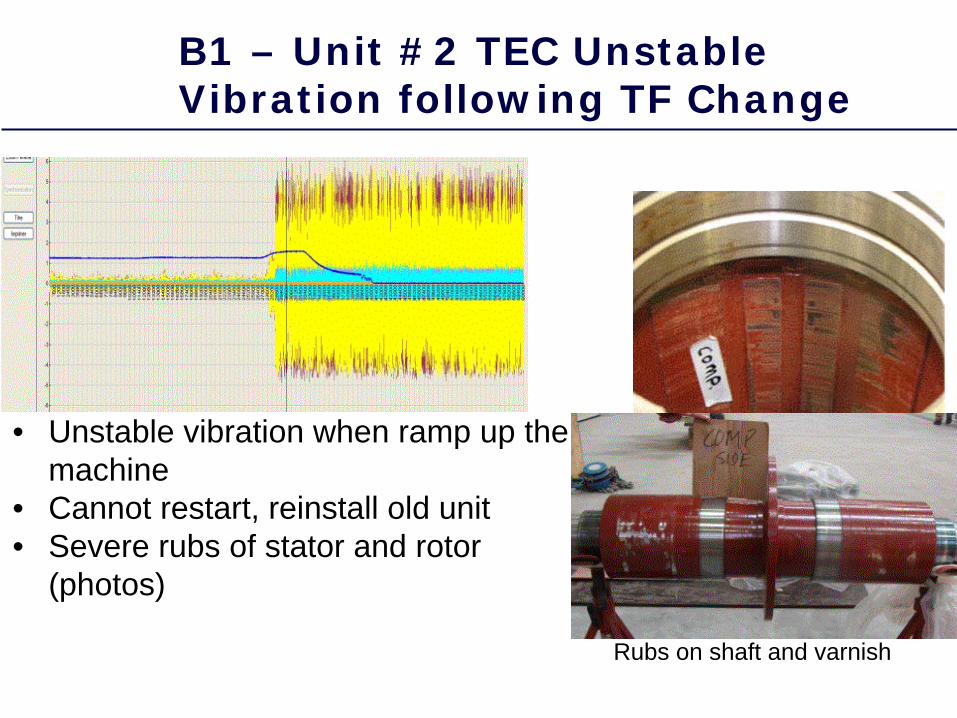
• Unstable vibration when ramp up the machine
• Cannot restart, reinstall old unit• Severe rubs of stator and rotor
(photos)
Rubs on shaft and varnish
B1 – Unit #2 TEC Unstable Vibration following TF Change
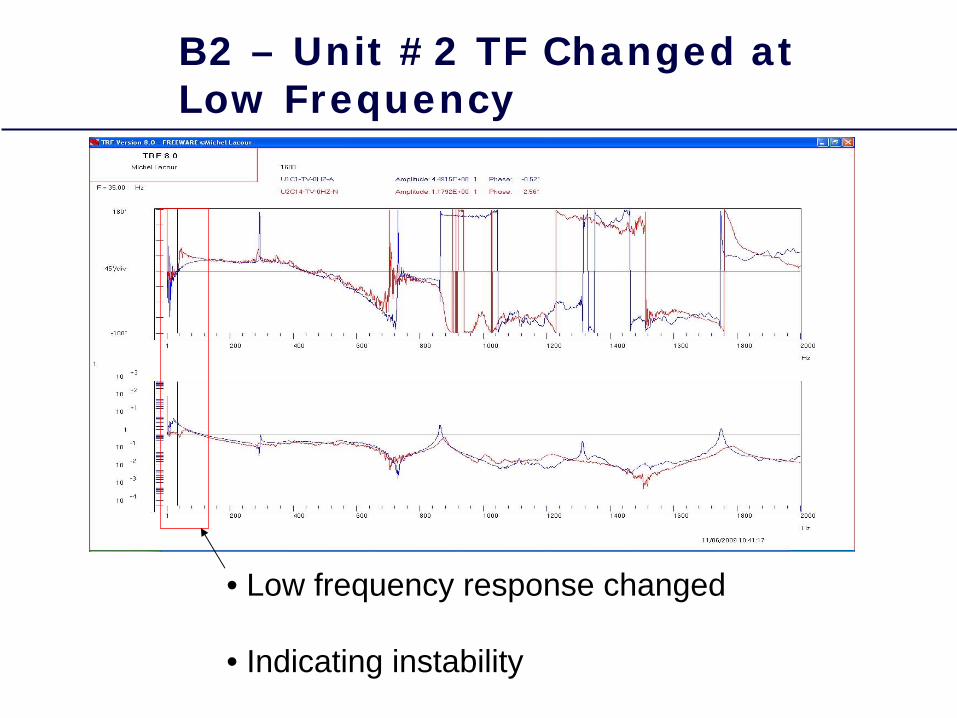
• Low frequency response changed
• Indicating instability
B2 – Unit #2 TF Changed at Low Frequency
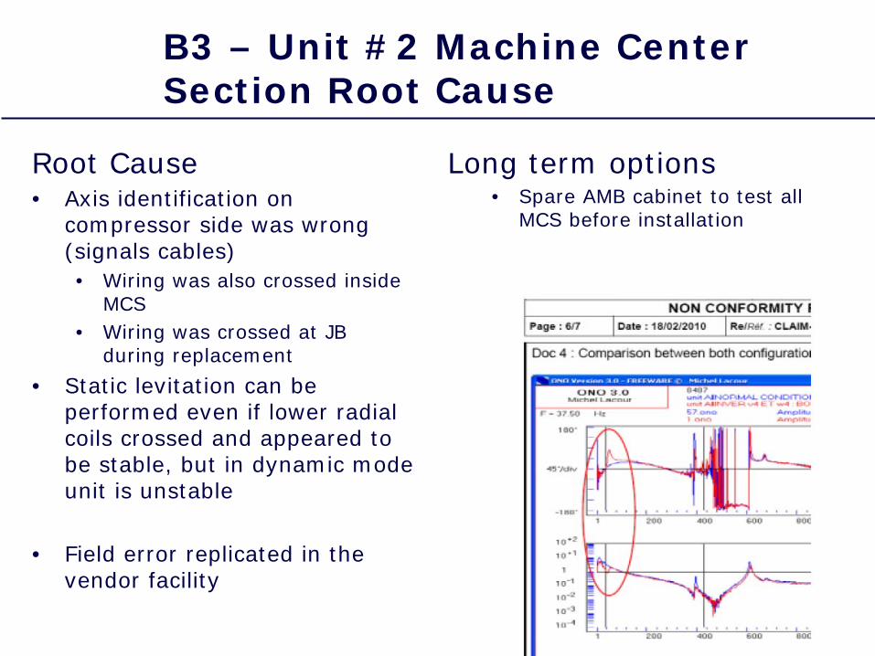
Root Cause • Axis identification on
compressor side was wrong (signals cables)• Wiring was also crossed inside
MCS • Wiring was crossed at JB
during replacement
• Static levitation can be performed even if lower radial coils crossed and appeared to be stable, but in dynamic mode unit is unstable
• Field error replicated in the vendor facility
B3 – Unit #2 Machine Center Section Root Cause
Long term options• Spare AMB cabinet to test all
MCS before installation
Summary
• Overviewed 2 unique Failure Modes and provided insight and steps to take to overcome the problems – technical interaction between Operator and OEMs are key
… timely and complete information vital
• These and other Lessons Learned have been fed back to OEM and incorporated into Design Specification for incorporation into future projects

Thank YouThank You