Embed Size (px)
Citation preview

8/10/2019 Turbine Maintainance
http://slidepdf.com/reader/full/turbine-maintainance 1/9
Condition Monitoring of SteamTurbines by Performance Analysis
Author : Ray Beebe , FIEAust CPEngMonash University Gippsland School of Engineering Churchill, Victoria 3842 Australia
This paper was originally presented at the 52nd Conference of the Machinery Failure PreventionSociety, Virginia Beach, April 1998
Abstract Steam turbines today are required to run for well beyond their intended lifetimes. Openingup machines for inspection is expensive, and owners need to consider all relevant information inmaking the decision. Problems in steam turbines which reduce machine efficiency and output, suchas deposits on blades and erosion of internal clearances, can be detected and monitored usingcondition monitoring by performance analysis. The paper outlines with some examples somecondition monitoring techniques which have contributed to running some large machines for up to 17years without opening high pressure sections.
In machines with an HP-IP opposed-flow casing, increased N2 packing internal steam leakage canoccur from the high pressure turbine section into the intermediate pressure section has a large effecton output and efficiency. The application of a simple test method for estimating this leakage explainedobserved poor performance on two sets.
Key Words: condition monitoring; optimisation; plant performance; predictive maintenance;steam turbines; testing; N2 packing
INTRODUCTIONSteam turbine generators are reliable machines, and often operate continuously for many months.Such operation at steady outputs can lead to deposition from the steam on the fixed and movingblades. Deposits cause output and efficiency to drop, by reducing the efficiency of energy transfer andeventually restricting steam flow. This occurs less on sets which vary in load, as they undergo aregular bladewashing effect.
Where a machine is taken from service, coastdown and running up through shaft bending criticalspeeds can allow momentary rubbing at the internal seals. The resulting enlarged flow area canreduce the internal efficiency, such that less energy is extracted from the steam. This also resultsfrom internal leakage within a casing which allows steam to bypass blading stages. These effects areparticularly evident on the turbine design with both High Pressure and Intermediate Pressure sectionsin the one casing, with flow in opposite directions.
Retractable packings have been developed by manufacturers and after-market suppliers. These avoidshaft rubbing as they do not close into their normal clearances until the machine is near operatingspeed, having passed through the bending critical speed or speeds.
Vibration analysis can detect the occurrence of such shaft rubbing and other conditions of the rotorline, but cannot detect the extent of internal wear or deposition. It is well suited for other quite differentfailure modes, such as when blades or parts of them come off and cause consequential damage. Aswith the application of all condition monitoring, the rule is to choose techniques to match the likelyfailure/wearout modes. As steam turbines are critical machines, all the main techniques have theirplace.
Performance analysis can be applied to most machines, rotating and stationary. It is the one conditionmonitoring technique which allows the optimum time for restorative maintenance to be calculated,where the deterioration results in increased fuel consumption, or in reduced output, or both. (Beebe1998)
8/10/2019 Turbine Maintainance
http://slidepdf.com/reader/full/turbine-maintainance 2/9
For some plant items, it is possible to use the normal plant instruments and data processing system todetermine condition parameters. (Beebe 1998a). In the case of steam turbines, a more refinedmethod using test quality instruments is needed to give warning well in advance of changes evidentfrom permanent instrumentation systems. (Groves 1996).
This paper describes some performance tests used for monitoring turbine condition and theirapplication.
MAINTENANCE OF LARGE STEAM TURBINE GENERATORSLarge steam turbines have usually between two and five individual casings. Manufacturers vary intheir recommendations for opening up a casing for inspection and refurbishment. (Tezel, 1989).Manufacturers have a vested interest in supply of spare parts, and therefore cannot be expected to beunbiased in their recommendations. The author well remembers walking through the works of onemanufacturer and seeing several HP casings in for overhaul. The accompanying engineer said "offthe record" that most of them would not justify the work!
An outage for such work on one casing may take several weeks, and cost millions of dollars. Inmaking this decision, plant owners need all the relevant information. Condition monitoring by
performance testing has been used to extend time between opening of casings to up to 17 years,making its cost/benefits very favourable. (Beebe 1995, Vetter et al 1989). The overhaul decisionshould not be made unless there is a compelling technical or economic reason for opening a casing.
A current EPRI project is aimed at extending the accepted interval between overhauls (McCloskey etal 1995).
It should be accepted that an outage after such a long time in service will probably take longer than ifscheduled more frequently, as distortion is likely to have occurred, and parts such as casing studs willprobably need replacement (Coade 1993). Once a casing is opened and clearance measurementsmade, it is possible to estimate the performance improvements achievable by refurbishment and so
justify the expenditure (Kuehn 1993; Sanders 1989). However, it is clearly preferable to try anddetermine the internal condition by testing, and use this information to help make the decision as tothe extent of overhaul.
In Table 1, the main wearout problems with steam turbines are summarised, together with an outlineof how how condition monitoring can detect them.
Part affected Wearout problem Comments, suitable condition monitoring
Blading
Erosion by solidparticles(also erosion bywater droplets on latter LPblades)
Usually occurs gradually, worst at inlet blading. Lessusual on sets with drum boilers and/or sub-critical inletsteam conditions, or with bypass systems. Performanceanalysis detects.
Blading Parts breaking off Usually sudden. Vibration analysis and Performanceanalysis detects.
Bearings Scoring damage towhitemetal
Performance analysis, vibration analysis, wear particles inoil (but representative sampling at each bearing is rare).
RotorsRubbing, temporaryunbalance, cracking,misalignment
Vibration analysis, and off-line, some NDT (not detailed inthis paper)
Valvespindles
Shaft andinterstageglands (seals)
Leakage due to wear,distortion, breakage
Likely to occur gradually, but can be sudden.Performance analysis detects.
Effect of seal wear is relatively greater for HP blading. Forimpulse machines, the relative lost output for each 25µmincrease above design clearance of about 600µm is:
HP: blade tips, 5kW; interstage seals, 6kW per stage;
8/10/2019 Turbine Maintainance
http://slidepdf.com/reader/full/turbine-maintainance 3/9
Casing joints
LP manholegaskets
Internal steampiping andfittings
end glands 15 to 25kW.
IP: blade tips, 2.5kW; interstage 2kW per stage; endglands 5kW
LP: blade tips and interstage, 1.5kW per stage; endglands 2kW.
For reaction blading, the effect will be greater.
Steam valvestrainers
Valvespindles
Blading
Deposits (more prevalentwith base loaded sets ascyclic loading tends tohave a blade washingeffect).
Likely to occur gradually, mostly in areas around 260°C.Some on-load blade washing occurs with forced steamcooling. Performance analysis detects. Blade surfaceroughness has biggest effect at higher steam pressures.One case gave 17% drop in output from deposits varyingbetween 250 to 2300 µm in thickness.
Permissible roughness for LP blading can be 100×coarser than for HP blading. One test with surface finishequivalent to 500 grit emery paper caused 5% to 7% lessefficiency in HP blading, about 2% in LP.
Generatorrotor, stator Insulation faults Electrical plant testing (several techniques (not detailed in
this paper)
Condenser Air inleakageTube fouling Performance analysis (not detailed in this paper)
Feedwaterheaters
Air inleakage, tube foulingby scale or oil Performance analysis (not detailed in this paper)
Valves - HP,IP bypass, etc Leakage Performance analysis. Acoustic leakage detection (not
detailed in this paper) is also possible.
OVERALL CONDITION INDICATORThe basic method of monitoring steam turbine internal condition is the Valves Wide Open test (ASME1985). Essentially, the generator is used as a transducer to measure the power output of the turbineat set datum conditions. Here are the details for a typical large reheat condensing set, the standardtype in nearly all fossil-fired power stations:
The inlet area for steam flow is set to datum by opening the steam control (ie governor) valves fully. Thisshould be verified by direct measurement at the valve power servos, rather than relying on control roomindicators. Fully open is the only truly repeatable setting.
The temperatures of main inlet and hot reheat steam are set as close to datum as can be achieved. Thisis usually the same as the rated values.
The inlet pressure is set to the datum value. As most turbines have capacity beyond their nameplaterating, the standard inlet steam pressure may need to be below the rated value if undesirably high
outputs would result. Condenser pressure is largely a function of seasonal conditions and weather, and is usually taken at the
best attainable on the day.
Extractions to feedwater heaters should be all fully open. If feedwater heater unreliability means thatsome heaters are out of service for long periods, that condition may have to be used as datum, unless amethod of allowing for this effect on turbine output can be derived.
Test readings during as test run of an hour or so are carefully made using calibrated test instruments,with two separate measurements of each point. Readings of test transducers can be made manually,but it is now usual to use a data logger coupled with a computer. With the exception of some minorflows read from plant instruments and used only in correction factors, test measurements of flow arenot made. This simplifies the test considerably and minimises the cost considerably compared withthe full heat rate test used for the initial acceptance tests for guarantee checks.
8/10/2019 Turbine Maintainance
http://slidepdf.com/reader/full/turbine-maintainance 4/9
The generator MW output over about an hour of steady operation is read using test instruments, andcorrected for any variations from the datum terminal conditions. For example, if the condenserpressure on the test is higher than the datum, then the turbine output will be less that which would beexpected at datum condenser pressure. Corrections are usually provided by the manufacturer for usein the initial acceptance tests but can be obtained using cycle modelling programs or from specialtests. With the instrument calibration information available, the calculations are usually performed
immediately following the tests.
Significant changes are often small, and it is unlikely that they can be detected by the permanentinstrumentation and data processing systems fitted for operation and monitoring (Groves, 1996). Thismay be possible with highly stable transducers of recent design, or with adequate calibrationarrangements.
EXAMPLE OF VWO TESTSTests run on a turbine generator some years apart and at different seasons gave these results: Test data TEST A Correction factor TEST B Correction factor
Generator Output MW 355.8 349.7
Steam Pressure - Main kPa 12155 1.02285 12255 1.02053Steam Temperature - Main °C 529.5 0.99832 526.7 0.99773
Steam Temperature - Reheat °C 525.8 1.0101 539.5 0.99873
Reheater Pressure Drop % 6.76 0.99814 6.03 0.99633
Condenser Pressure - kPa 9.34 1.01225 12.44 1.03615
Generator Power Factor 0.923 1.00012 0.945 1.00064
Steam Temp. Cont. Spray - Main kg/s 6.5 0.99889 24.6 0.99584
Steam Temp. Control Spray - Reheaterkg/s 0 1 0 1
Final Feedwater Temperature °C 234.9 1.0005 230.5 0.98957
Combined correction factor 1.04741 1.03521
Corrected VWO Output MW 372.7 362
From experience, the reduction observed is significant. Further tests would be performed to ascertainparameters of condition of individual machine components which can be separately opened. Data forthese is often gathered concurrently with the VWO tests.
SECTION PARAMETERSMeasurement of temperatures and pressures at available points along the turbine enable condition ofindividual sections to be assessed. If the VWO Output has reduced, then the section or sectionscausing the reduction can be localised. Table 2 gives some of the parameters used and theirapplication. The following sections give examples of some of these in use. Parameter Comments
Steam strainer pressuredrop
Best measured with a differential pressure transducer rather than anupstream and a downstream pair. An increase indicates blockage,probably from metal particles from boiler tube welding repairs.
Section enthalpy dropefficiency (superheatedsteam sections)
Calculated using steam tables computer program. A drop indicates bladefouling, or erosion damage.
Section pressure ratios
Stage pressures can be corrected to standard inlet pressure, but anyerror in measuring it is applied to all the stage pressures. Ratios use onlythe outlet and inlet pressures of each section. Changes show up erosion
or deposition.Corrected First Stage At VWO, proportional to steam flow through the turbine, indicates first

8/10/2019 Turbine Maintainance
http://slidepdf.com/reader/full/turbine-maintainance 5/9
pressure stage condition. Increase points to upstream erosion, or downstreamblockage, and vice versa.
Extraction temperatures tofeedheaters in superheatedsections
According to design, a higher than expected steam inlet temperaturemay indicate relative internal bypassing leakage in the turbine upstreamof the extraction point..
Extraction temperatures tofeedheaters in saturatedsteam sections
Increases above saturation temperature indicate leakage of steam froma stage upstream of the extraction point.
Drain line temperaturesfrom casings, or from shaftseal (gland) sections
Where available, these may indicate relative leakage, according todesign. A similar approach can be used for points before and after pipe
junctions of two streams of different temperatures. Pipe surfacetemperatures are sufficient for repeatable assessment.
Estimated N2 packingleakage (on turbines withcombined HP-IP casings)
Test by varying relative inlet steam temperatures and observing effect onIP enthalpy drop efficiency.
Table 2: Some parameters of condition of individual turbine sections
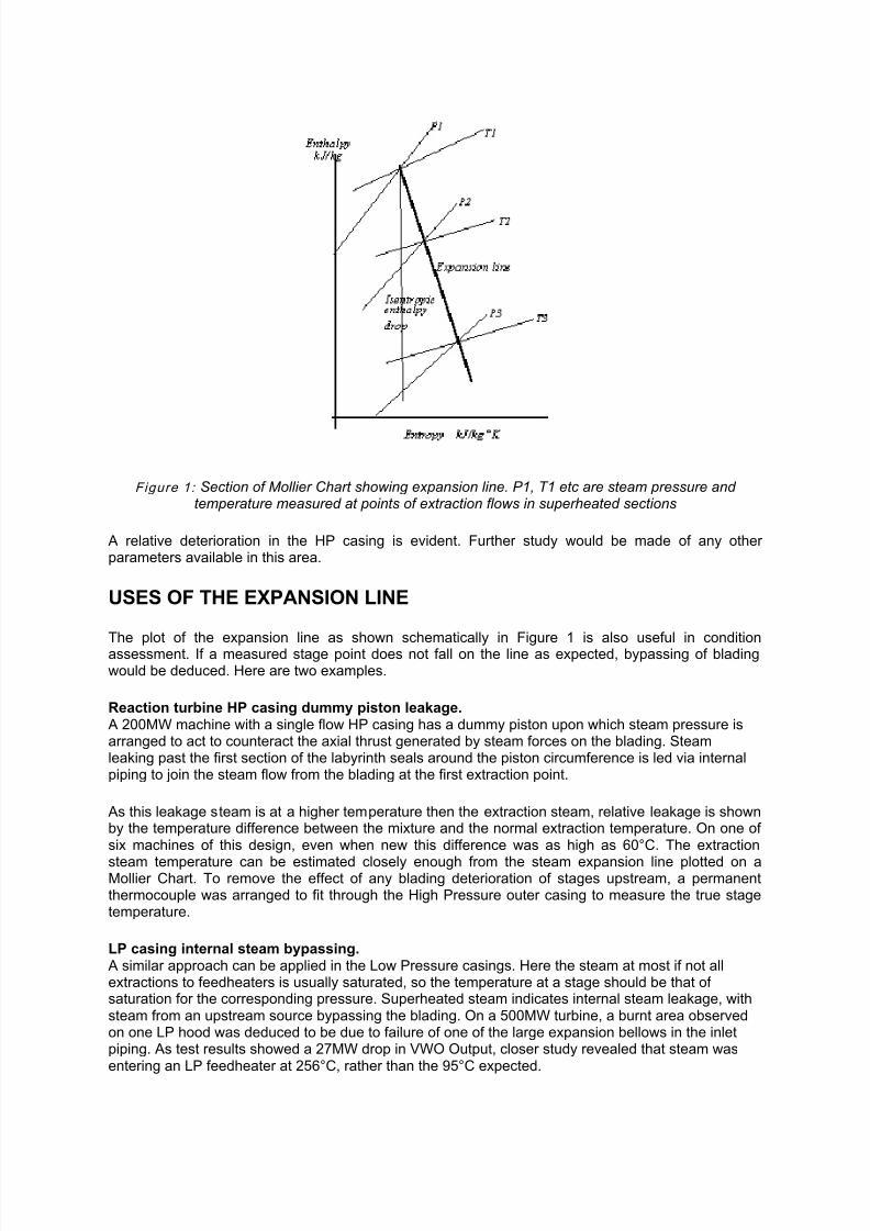
ENTHALPY DROP EFFICIENCY TESTS A main condition indicator for a turbine casing, or blading section, is the enthalpy drop efficiency - theactual enthalpy drop divided by the isentropic enthalpy drop. Figure 1 illustrates this parameter on asection of the Mollier chart. It is usually between 85% and 90%, with typical repeatability for HPcasings, ±0.9%; IP casings ±1.0%.
This can only be determined for the superheated steam sections. For assessment across a turbinesection within a casing, stage conditions are usually available in steam extraction lines to feedwaterheaters. Naturally, these cannot be used for temperature measurement if the associated feedwaterheater is out of service.
In the two test series given earlier, the corresponding enthalpy drop efficiencies were:
Test A Test B
High Pressure casing (from Main Stop Valve inlet) 85.5% 83.8%
Intermediate Pressure casing (from Reheat Stop Valve inlet) 88.2% 88.3%
8/10/2019 Turbine Maintainance
http://slidepdf.com/reader/full/turbine-maintainance 6/9
Figure 1: Section of Mollier Chart showing expansion line. P1, T1 etc are steam pressure andtemperature measured at points of extraction flows in superheated sections
A relative deterioration in the HP casing is evident. Further study would be made of any otherparameters available in this area.
USES OF THE EXPANSION LINE
The plot of the expansion line as shown schematically in Figure 1 is also useful in conditionassessment. If a measured stage point does not fall on the line as expected, bypassing of bladingwould be deduced. Here are two examples.
Reaction turbine HP casing dummy piston leakage. A 200MW machine with a single flow HP casing has a dummy piston upon which steam pressure isarranged to act to counteract the axial thrust generated by steam forces on the blading. Steamleaking past the first section of the labyrinth seals around the piston circumference is led via internalpiping to join the steam flow from the blading at the first extraction point.
As this leakage steam is at a higher temperature then the extraction steam, relative leakage is shownby the temperature difference between the mixture and the normal extraction temperature. On one ofsix machines of this design, even when new this difference was as high as 60°C. The extraction
steam temperature can be estimated closely enough from the steam expansion line plotted on aMollier Chart. To remove the effect of any blading deterioration of stages upstream, a permanentthermocouple was arranged to fit through the High Pressure outer casing to measure the true stagetemperature.
LP casing internal steam bypassing. A similar approach can be applied in the Low Pressure casings. Here the steam at most if not allextractions to feedheaters is usually saturated, so the temperature at a stage should be that ofsaturation for the corresponding pressure. Superheated steam indicates internal steam leakage, withsteam from an upstream source bypassing the blading. On a 500MW turbine, a burnt area observedon one LP hood was deduced to be due to failure of one of the large expansion bellows in the inletpiping. As test results showed a 27MW drop in VWO Output, closer study revealed that steam wasentering an LP feedheater at 256°C, rather than the 95°C expected.
8/10/2019 Turbine Maintainance
http://slidepdf.com/reader/full/turbine-maintainance 7/9
It was deduced from careful study of construction details from available drawings that the secondbellows had failed. This conclusion was confirmed by the manufacturer.
USE OF STAGE PRESSURESExcept for the first stage of nozzle-governed turbines, and the last stage, the pressures at stagesalong a steam turbine are closely proportional to steam flow, and therefore to load at datumconditions.
During starting up of a 200MW turbine, great difficulty was experienced with extremely high in-leakage into its condenser. Despite all the air removal pumps running, condenser pressure was stillwell above the normal. During loading, the problem disappeared - above 40% load.
By examining the stage pressure vs load curves, it was noticed that the pressure to LP feedheater 2was below atmospheric until above 40% load, when it becomes positive. The air leak was thereforesomewhere in the turbine system connected to that point. Meticulous study of piping drawings andinspection of the machine revealed a sprung joint in a flange joint in the leakoff piping from a shaftend gland. This piping led to the LP2 feedheater.
Such investigations are not necessarily easy - few drawings may be available, the piping andconnections may be under lagging, access is required to areas of the machine which are probablydark, noisy, certainly hot, and special staging may need to be built.
INTERNAL LEAKAGE OF COMBINED HP/IP CASINGSMany large turbines of US design have a combined High Pressure and Intermediate Pressure casingwith steam flows in opposing directions. The central gland between them is commonly known as theN2 packing. In good condition, there is leakage of about 1% of main steam inlet flow from HP to IPsections through this gland. Any increase means that some of the steam initially supplied to theturbine does not pass through the HP blading, then through the reheater, but instead directly to the IPblading.
As this gland is near the centre of the rotor span, rotor deflection during starting up and coastdownoperation can cause rubbing, and thereby increase the clearances. Leakage has a dramatic effect onturbine efficiency, as the leakage flow effectively circulates in a non-reheat cycle of lower efficiency.Typically, leakage of 1% of initial steam supplied to the turbine results in an output reduction of 0.3%and efficiency reduction of about 0.16%.
Leakage flow enters after the steam temperature into the IP casing is measured, and because theleakage steam is at a lower temperature than hot reheat steam, the IP outlet steam will be at a lowertemperature and hence enthalpy. The result is to give an incorrect high value of IP enthalpy dropefficiency. Therefore, in routine testing of such turbines, if an increase in IP enthalpy drop efficiency isfound, then increased N2 gland leakage should be suspected.
The leakage steam flow cannot be measured, but there are two ways of estimating it to sufficientaccuracy for routine condition monitoring: Cotton (1993) and Booth (1984) and later EPRIpublications. The first method requires the running of IP enthalpy drop efficiency tests before and afteropening the packing blowdown valve, where fitted. A modification which gives better accuracy is toinstall a bypass line around the packing blowdown valve, with a flowmeter.
The alternative method requires no plant modifications. Tests are run where some differencesbetween main steam and reheat steam temperatures are arranged. This is readily done at ValvesWide Open by holding the hot reheat steam temperature constant while reducing the main steam inlettemperature. Three steps are suggested. At each test, the IP efficiency is calculated, and plottedagainst two assumed leakage flows. The intercept enables a reasonable estimate of the leakage flow.
A critical assessment of the accuracy is given in Haynes, et al (1995).
For the first test, at rated conditions, the enthalpy of the leakage steam is estimated at first stagepressure from a plot of the expansion line. The steam flow through the IP blading is assumed

8/10/2019 Turbine Maintainance
http://slidepdf.com/reader/full/turbine-maintainance 8/9
constant throughout the test series (as it is the sum of hot reheat flow and N2 leakage under allconditions). The enthalpy of the steam entering these blades can be calculated by heat balance forboth the initial conditions and for an assumed 10% leakage flow:
where: h3 = enthalpy of steam into Intermediate Pressure bladingh1 = enthalpy of steam leaking into IP blading through the N2 glandh2 = enthalpy of hot reheat steam entering the IP turbine.
The IP efficiency is plotted at datum and 10% leakage conditions. When these points are joined, theintersection of the lines gives a reasonable estimate of the actual leakage flow (Figure 2).
Figure 2: schematic plot of results for N2 gland leakage: x is estimated flow
EXAMPLE OF N2 GLAND LEAKAGE ASSESSMENTWhen new, two large turbines of the combined HP/IP casing type were found to have a thermalefficiency well below that expected. The test procedures, particularly the primary flow measurement,were closely examined, but no discrepancy could be found. In operation, there was difficulty in holdinghot reheat temperature down to the design values, and an extra desuperheating temperature controlspray station was added to the boiler. A significant portion of reheater tubing was also removed.
Some years later, routine tests were arranged to include the second approach described above. Theestimated N2 gland leakage flow was found to be 4 to 5 times the design value which had been usedin calculating the results of the original thermal efficiency tests. This was consistent with the reducedthermal efficiency and reheater problems. Inspection at the first overhaul confirmed that the N2 glandclearances were larger than design, as predicted by the tests, and had apparently been so since new.
REFERENCES AND FURTHER READING ASME (1985) Simplified procedures for routine performance tests of steam turbines ANSI PTC 6Sreport 1974, reaffirmed 1985
Beebe, R (1995) Machine condition monitoring MCM Consultants. ISBN 0 646 250884
Beebe, R (1998) Condition monitoring by performance analysis to optimise time for overhaul ofcentrifugal pumps MFPT Society 52nd Annual Meeting

8/10/2019 Turbine Maintainance
http://slidepdf.com/reader/full/turbine-maintainance 9/9
Beebe, R (1998a) Predictive maintenance by performance monitoring of plant MFPT Society 52nd Annual Meeting
Booth, J A & Kautzmann, D E (1984) Estimating the leakage from HP to IP turbine sections EPRIPlant Performance Monitoring Conference.
Coade, R W and Nowak, S (1993) Remaining life study of a 350MW HP/IP turbine Conference onpressure vessels and pipework, Sydney
Cotton, K C (1993) Evaluating and improving steam turbine performance Cotton Fact Inc ISBN 0 963995502
Groves, K (1996) Turbine steam path monitoring using plant DPA system unpublished degree majorproject Monash University
Haynes, C J; Medina, C A; Fitzgerald, M A (1995) The measurement of HP-IP leakage flow: thelargest source of uncertainty in code tests of low pressure turbines PWR-Vol 28 IEEE-ASME JointPower Generation Conference
Kuehn, S E (!993) Steam turbine technology keeps pace with demands Power Engineering
Leyzerovich, L (1997) Large Power Steam Turbines: Design and Operation Vol 2 PennWell ISBN 087814 716 0
McCloskey, T H; Pollard, M A and Schimmels, J N (1995) Development and implementation of aturbine-generator outage interval extension strategy PWR-Vol 28 ASME/IEEE International JointPower Generation Conference
Sanders, W P (1989) Efficiency Audit of the turbine steam path, classifying damage and estimatingunit losses ASME/IEEE International Joint Power Generation Conference
Tezel, F H et al (1989) Maintenance scheduling for steam turbine generators ASME/IEEEInternational Joint Power Generation Conference
Vetter, H & Schwiemler, G (1989) First turbine inspection after a 15-year operating period VGBKRAFTWERKSTECHNIK.


![Repair and maintainance of cracks [CIVIL ENGINEERING]](https://img.pdfslide.us/doc/110x75/588af83b1a28abf8548b5a6f/repair-and-maintainance-of-cracks-civil-engineering.jpg)