Embed Size (px)
Citation preview

FLO
W E
LE
ME
NT
S
737
Turbine flow meterModel : F902
Description
Specification
Flow chart
Process connection
Size
Material
Pressure rating
Temperature rating
Accuracy
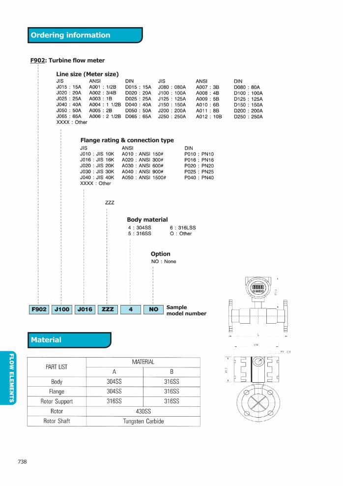
Ordering information
F902 J100 J016 ZZZ 4 NOSample model number
MaterialFLO
W E
LE
ME
NT
S
738
F902: Turbine flow meter
Line size (Meter size)
Flange rating & connection type
Body material
Option

FLO
W E
LE
ME
NT
S
739
Memo

1
2
3
4
5
6
7
8
10
12
14
16
18
20
ANSI/ASME B36.19M-1985
Steel Pipe Sch
5S 10S 40S 80S 10 20 30 STD 40 XS 60 80 100 120 140 160 XXS
21.34
26.67
33.40
42.16
48.26
60.33
73.03
88.90
101.6
114.3
141.3
168.3
219.1
273.1
323.9
355.6
406.4
457.2
508.0
558.8
609.6
660.4
711.2
762.0
1
2
3
4
5
6
8
10
12
14
16
18
20
22
24
26
28
30
1
1
2
3
Size O.DANSI/ASME B36.19M-1985
Stainless Steel Pipe Sch
FLO
W E
LE
ME
NT
S
740
Engineering reference data
Pipe dimensions
Nominal
Pipe SizeO.D SGP
Sch. No. & I.D
5S 10S 20S 20 30 40 60 80 100 120 140 160
A6
8
10
15
20
25
32
40
50
65
80
90
100
125
150
175
200
250
300
350
400
450
500
�
�
�
�
�
B
1
1
2
3
�
�
�
�
�
�
�
�
�
�
�
�
�
�
�
�
�
�
�
�
�
�
�
�
�

FLO
W E
LE
ME
NT
S
741
Engineering specification
Flow elements
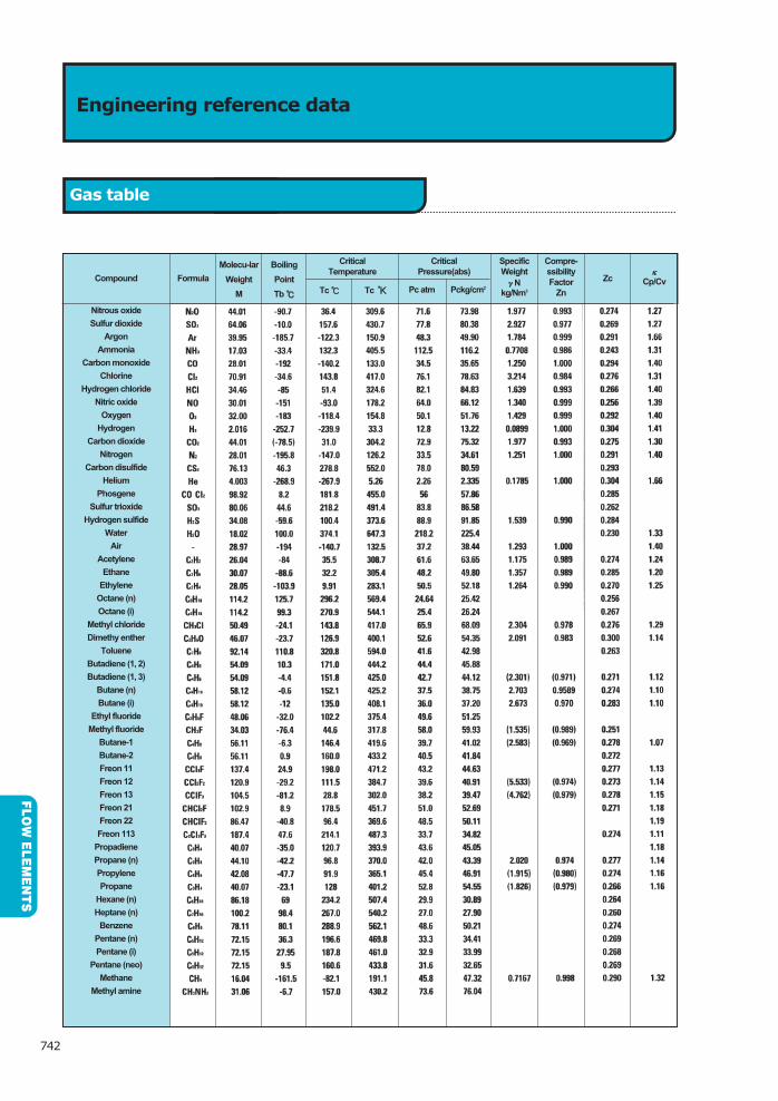
Engineering reference data
Gas table
FLO
W E
LE
ME
NT
S
742
Compound
Nitrous oxide
Sulfur dioxide
Argon
Ammonia
Carbon monoxide
Chlorine
Hydrogen chloride
Nitric oxide
Oxygen
Hydrogen
Carbon dioxide
Nitrogen
Carbon disulfide
Helium
Phosgene
Sulfur trioxide
Hydrogen sulfide
Water
Air
Acetylene
Ethane
Ethylene
Octane (n)
Octane (i)
Methyl chloride
Dimethy enther
Toluene
Butadiene (1, 2)
Butadiene (1, 3)
Butane (n)
Butane (i)
Ethyl fluoride
Methyl fluoride
Butane-1
Butane-2
Freon 11
Freon 12
Freon 13
Freon 21
Freon 22
Freon 113
Propadiene
Propane (n)
Propylene
Propane
Hexane (n)
Heptane (n)
Benzene
Pentane (n)
Pentane (i)
Pentane (neo)
Methane
Methyl amine
Formula
Molecu-lar
Weight
M
Boiling
Point
Tb � Tc � Tc ��
Critical
Temperature
Pc atm Pckg/cm2
Critical
Pressure(abs)
Specific
Weight
�Nkg/Nm3
Compre-
ssibility
Factor
Zn
Zc�
Cp/Cv

Engineering reference data
Chemical resistance of protection tubes
FLO
W E
LE
ME
NT
S
743
H2SO4
2HCL
HNO3
CH3CO2H
H3PO4
H2F2
HCI
HaOH
KOH
HCI(dry) HCI(wet)
HCI vapor
HF
H2(SiF6)
F
HaOH
CO2
SO2
Na5P3O10
CHCI
AIF3
Fatty Acid
NH3
NaCI
Cro4
H2O2
S(liquid)
CaCI2
Conce
nt
Tem
p.(�
)
304S
S
321S
S
316S
S
316S
S
316J
1LS
S
310S
S S
S
347S
S
Car
pent
er 2
0
Inco
nel
600
Nim
onic
Has
tello
y B
Has
tello
y C
Has
tello
y X
T it
aniu
m
Monel
Tan
talu
m
Tef
lon
Copper
Zir
coniu
m
Nic
kel
PV
C
Cuoro
-nic
kel
Alu
min
ium
Bra
ss
Lea
d
Com
mon
ste
el
50C
o-3
0Cr
Hay
nes
allo
y 25
Compound

FLO
W E
LE
ME
NT
S
744
Engineering reference data
Material specification
ASTM
A-105
A-181
A-181
A-182
A-182
A-182
A-182
A-182
A-182
A-182
A-182
A-182
A-182
A-182
A-182
A-182
A-182
A-182
A-350
A-350
A-350
��
��
��
��
���
��
��
��
���
��
�
���
����
���
����
��
���
���
��
��
�����
�����
�����
�����
�����
�����
���
�������
�������
����
�������
�������
������
��
�������
�������
��������
��������
���
��������
��
��������
������
��������
��
��������
�
�����
�����
�����
�����
� ��
Grade C%
Mn%
Si%
Ni%
Cr%
Mo%
PMax.
%
SMax.
%
T.S.Min.psi
(kg/mm2)
Y.SMin.psi
(kg/mm2)
ELMin%
Red.Min%
HB
Classifi-Cation
Chemistry Mechanical Properties

FLO
W E
LE
ME
NT
S
745
Engineering reference data
Temperature conversion tables
� � � � � � � � � � � � � � �
� � � � � �

� � � � � � � � � � � �
FLO
W E
LE
ME
NT
S
746
Engineering reference data
Temperature conversion tables

FLO
W E
LE
ME
NT
S
747
Engineering reference data
Unit conversion table

FLO
W E
LE
ME
NT
S
748
Engineering reference data
Unit conversion table

FLO
W E
LE
ME
NT
S
749
Engineering reference data
Unit conversion table

FLO
W E
LE
ME
NT
S
750
Engineering reference data
Unit conversion table

FLO
W E
LE
ME
NT
S
751
Engineering reference data
Unit conversion table

FLO
W E
LE
ME
NT
S
752
Engineering reference data
Unit conversion table

FLO
W E
LE
ME
NT
S
753
Engineering reference data
Unit conversion table
Diameter
ratio
�
Single
90 bend or tee
(flow from one
branch only)
Upstream Downstream
Upstream Downstream
�
Two or more
90 bends in
the same plane
�
Two or more
90 bends in
different planes
Reducer
(2D to D over
a length of 3D)
Expander
(0.5D to D over
a length of 1.5D)
Glove
valve
fully open
Glove
valve
fully open
All
fittings
included
in this
table
�
Diameter
ratio
�
Single 90
short radius
bend
� Two or more
90 bends in
the same plane
�
Two or more
90 bends in
different
planes
Reducer
3D to D over
a length of
3.5D
Expander
0.75D to D
over a
length of D
Glove
valve
fully open
All
fittings
included
in this
table
�
Two or more
90 bends in
different
planes with
straightening
vanes
�

FLO
W E
LE
ME
NT
S
754
Memo

Reflex type level gauge Model : L100 Series
755
Description
Model
LE
VE
L G
AU
GE
GLA
SS
Chamber material - Carbon steel, stainless steelMAX. pressure - 4MPaVessel connection - 15A, 20A, 25A
Chamber material - Carbon steel, stainless steelMAX. pressure - 24MPaVessel connection - 15A, 20A, 25A
Specification
Type - ReflexVisible length - 170 to 4000mm MaxMaximum no. of section - 13 sectionVessel connection - 1/2”~2”(15A~50A) flanged by your requiredChamber test pressure - Working pressure X 1.5

LE
VE
L G
AU
GE
GLA
SS
756
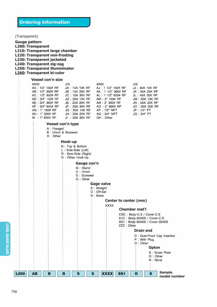
Ordering information
L100 AE A B S 0 XXXX S1C P N Sample model number
(Reflex)
Gauge patternL100: ReflexL110: Reflex large chamberL120: Reflex non-frostingL130: Reflex jacketedL140: Reflex zig-zagL150: Reflex illumininatorL160: Reflex bi-color
Vessel con’n size
Vessel con’n type
Hook-up
Gauge con’n
Gage valve
Center to center (mm)
Chamber mat’l
Drain end
Opton

Transparent type level gaugeModel : L200 Series
LE
VE
L G
AU
GE
GLA
SS
757
Description
Model
Specification
Chamber materialCarbon steel, stainless steel
MAX. pressure4MPa
Vessel connection15A, 20A, 25A
Chamber materialCarbon steel, stainless steel
MAX. pressure10MPa
Vessel connection15A, 20A, 25A
Chamber materialCarbon steel, stainless steel
MAX. pressure24MPa
Vessel connection15A, 20A, 25A
Type - TransparentVisible length - 170 to 4000mm MaxMaximum no. of section - 13 sectionVessel connection - 1/2”~2”(15A~50A) flanged by your requiredChamber test pressure - Working pressure X 1.5
LE
VE
L G
AU
GE
GLA
SS
758
Ordering information
L200 AB B B S S XXXX SS1 D SSample model number
(Transparent)
Gauge patternL200: TransparentL210: Transparent large chamberL220: Transparent non-frostingL230: Transparent jacketedL240: Transparent zig-zagL250: Transparent illumininatorL260: Transparent bi-color
Vessel con’n size
Vessel con’n type
Hook-up
Gauge con’n
Gage valve
Center to center (mm)
Chamber mat’l
Drain end
Opton

LE
VE
L G
AU
GE
GLA
SS
759
Large chamber type level gaugeModel : L110, L210
Description
Model
Model - L110
Chamber material - Carbon steel, stainless steelMAX. pressure - 14MPaVessel connection - 25A, 40A, 50A
Model - L220Chamber material - Carbon steel, stainless steelMAX. pressure - 14MPaVessel connection - 25A, 40A, 50A
LE
VE
L G
AU
GE
GLA
SS
760
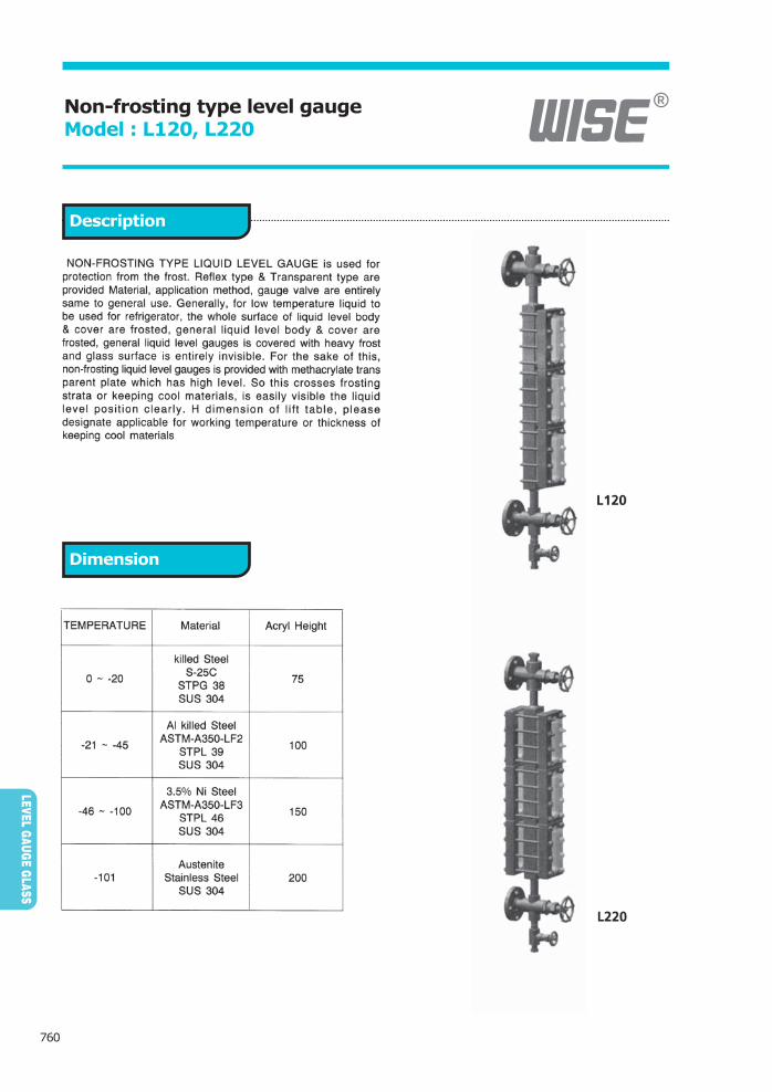
Non-frosting type level gaugeModel : L120, L220
Description
Dimension

Heating type level gauge zig-zag type level gauge Model : L130, L230
LE
VE
L G
AU
GE
GLA
SS
761
Description
Model
Model - L130Material - Carbon steel, stainless steelMAX. pressure - 4MPaVessel connection - 15A, 20A, 25A
Model - L230Material - Carbon steel, stainless steelMAX. pressure - 24MPaVessel connection - 15A, 20A, 25A

LE
VE
L G
AU
GE
GLA
SS
762
IlluminatorModel : L150, L250
Description
Specification
Electricity

Magnetic float type level gaugeModel : L300 Series
LE
VE
L G
AU
GE
GLA
SS
763
Model
Standard specification
Column size2B (50A)
ScheduleSCH. 10S, 20S, 40S, etc.
Flange rating150LB~1500LB (10K~63K)
MaterialSUS 304, SUS 316, SUS 316L, PVC, etc.
Indicator methodMagnetic
MAX. pressure19MPa
MAX. temperature
350�
Specific gravityMIN. 0.45
ViscosityMAX. 50 CP
Standard specification
Column size21/2B (65A)
ScheduleSCH. 10S, 20S, 40S, etc.
Flange rating150LB~1500LB (10K~63K)
MaterialSUS 304, SUS 316, SUS 316L, etc.
Indicator methodMagnetic
MAX. pressure19MPa
MAX. temperature
350�
Specific gravityMIN. 0.45
ViscosityMAX. 50 CP

LE
VE
L G
AU
GE
GLA
SS
764
Ordering information
L300 JG S2T XXXX C50 P NO Sample model number
(Magnetic float)
Gauge patternL300: Magnetic floatL310: Magnetic float lining
Vessel con’n size
Chamber material
Center to center (mm)
Chamber size
Drain end
Opton
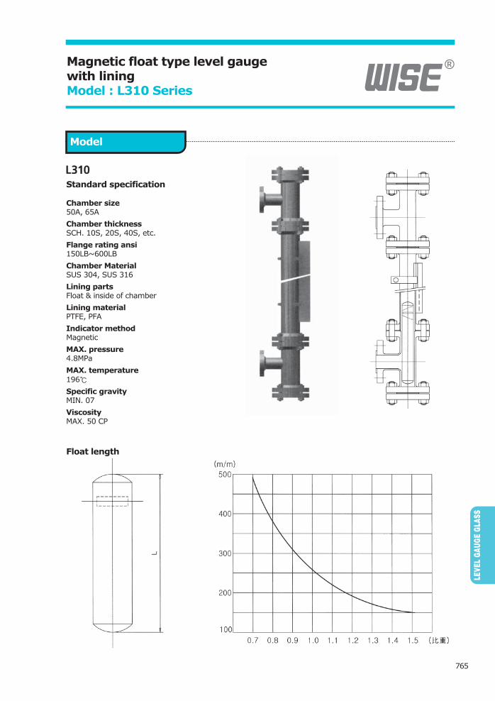
Magnetic float type level gauge with lining Model : L310 Series
LE
VE
L G
AU
GE
GLA
SS
765
Model
Standard specification
Chamber size50A, 65A
Chamber thicknessSCH. 10S, 20S, 40S, etc.
Flange rating ansi150LB~600LB
Chamber MaterialSUS 304, SUS 316
Lining partsFloat & inside of chamber
Lining materialPTFE, PFA
Indicator methodMagnetic
MAX. pressure4.8MPa
MAX. temperature
196�
Specific gravityMIN. 07
ViscosityMAX. 50 CP
Float length

LE
VE
L G
AU
GE
GLA
SS
766
L300 option level switch / transmitter
Description
Specification
Operation

Magnetic float type liquid level transmitterModel : L350
LE
VE
L G
AU
GE
GLA
SS
767
Standard features
Mechanical Electrical
Service intended
Display
Accuracy
Measuring range
Operating thmperature
Parameter adjustment
Wet part material Input power
Current consumption
Display
Display range
Parameter input
Output
Flange size
Flange material
Header

LE
VE
L G
AU
GE
GLA
SS
768
Ordering information
L350 J080 E 5 S5 XXXX L A Sample model number
L350: Magnetic float type level transmitter
Flange size
Enclosure class
Flange material
Wet part material
Measuring range (Guide pipe)
Local display
Output signal

TubuLar gaugeModel : L400
LE
VE
L G
AU
GE
GLA
SS
769
Description
Model
Specification
Valve materialCarbon steel, stainless steel
Valve type WISE standard
Size15A, 20A, 25A
Valve materialCarbon steel, stainless steel
Valve type WISE standard
Size15A, 20A, screwed
Valve materialPVC
Size15A, 20A, 25A
Working pressure - 0.48MPa(MAX.)
Working temperaure - 170�(MAX.)Hydro test pressure - 0.73MPa

LE
VE
L G
AU
GE
GLA
SS
770
Ordering information
L400 AD S1T XXXX P XXXX N Sample model number
(Tubular)
Gauge patternL400: Tubular
Vessel con’n size
Valve & tube material
Center to center (mm)
Drain end
Opton

Two - color type level gaugeModel : L500, L510 Series
LE
VE
L G
AU
GE
GLA
SS
771
Features of two colors water level gauge

LE
VE
L G
AU
GE
GLA
SS
772
Ordering Information
L500 AR OH SS XXXX A ZZ NO Sample model number
(Tow color)
Gauge patternL500: Tow color transparentL510: Tow color multi-port
Vessel con’n size
Hook-up
Gage valve
Center to center (mm)
Chamber mat’l
Drain end
Illuminator case material

Transparent & two - color type level gaugeModel : L500 Series
LE
VE
L G
AU
GE
GLA
SS
773
Description
Dimensions
Specifications
Model

LE
VE
L G
AU
GE
GLA
SS
774
Two - color Multi - port type level gaugesModel : L510 Series
Description
Specifications
Model

pressure / temperature rating of L500 series
LE
VE
L G
AU
GE
GLA
SS
775
No. of
Ports
Visual
Length
(VL)
Gauge
Length
(G.L)
Installation
Length
(C to C)
L1 L2
Port
Pitch
(P)

LE
VE
L G
AU
GE
GLA
SS
776
Construction and functioning
In the case of boiler water
In the case of steam

LE
VE
L G
AU
GE
GLA
SS
777
Engineering reference data
Hook - ups
Glass for high pressure & high temperature Glass type
Glass Sizeand
No of Sec
#1�1
#2�1
#3�1
#4�1
#S4�1
#5�1
#6�1
#7�1
#S7�1
#8�1
#9�1
#10�1
#S4�2
#5�2
#6�2
#7�2
#S7�2
#8�2
#9�2
#10�2
#6�3
#7�3
#S7�3
#8�3
#9�3
#10�3
#7�4
#S7�4
#8�4
#9�4
#10�4
#7�5
#S7�5
#8�5
�#9�5
�#10�5
�#7�6
�#8�6
�#9�6
�#7�7
�#8�7
�#9�7
�#7�8
�#8�8
�#9�8
V.L G.LStandard O.L
TB SS TB SS
Standard C to C WeightWithoutValves
V.L G.LStandard O.L
TB SS TB SS
Standard C to C WeightWithoutValves
Glass Sizeand
No of Sec

LE
VE
L G
AU
GE
GLA
SS
778
Engineering reference data
Dimensions items
Codes for hook - up

LE
VE
L G
AU
GE
GLA
SS
779
Engineering reference data
Nozzle orientations of WISE direct reading liquid level gauges

LE
VE
L G
AU
GE
GLA
SS
780
Engineering reference data
Gauge connections

LE
VE
L G
AU
GE
GLA
SS
781
Engineering reference data
Vessel connections
F
U
S
P
N
W
K
Z

LE
VE
L G
AU
GE
GLA
SS
782
Engineering reference data
Flange dimensions for gauge valves
Nominal Size Dimensions of Flange Bolt Hole
mm in
OutsideDiameterof Flange
Dt1
t(t=t1+f)
f Diameterg
Diameter ofBolt Circle
C
Numbern
Diameterh
Standard
CLASS 150ANSI B 16.5
TABLE HB
JPI-7S-15-84
CLASS 300ANSI B 16.5
TABLE H11
JPI-7S-15-84
CLASS 600ANSI B 16.5
TABLE H17
JPI-7S-15-84
CLASS 900ANSI B 16.5
TABLE H20
JPI-7S-15-84
CLASS 1500ANSI B 16.5
TABLE H23
JPI-7S-15-84
CLASS 2500ANSI B 16.5
TABLE H26
JPI-7S-15-84

LE
VE
L G
AU
GE
GLA
SS
783
Engineering reference data
Ring type joint
Nominal Size Pitch DiameterDepth Width Groove
Radius at Bottom
Diameter ofRaised Potion
Dimensions of Flange
Standard
CLASS 150ANSI B 16.5
TABLE H5
JPI-7S-15-84
CLASS 300ANSI B 16.5
TABLE H5
JPI-7S-15-84
CLASS 600ANSI B 16.5
TABLE H5
JPI-7S-15-84
CLASS 900ANSI B 16.5
TABLE H5
JPI-7S-15-84
CLASS 1500ANSI B 16.5
TABLE H5
JPI-7S-15-84
CLASS 2500ANSI B 16.5
TABLE H5
JPI-7S-15-84

LE
VE
L G
AU
GE
GLA
SS
784
Engineering reference data
Dimensions of other flanges (Male and female face, tongue and groove flange)
NominalSize
mm
15
20
25
1 1/2
50
in
1/2
3/4
1
73.0
2
Larg
e m
ale
Larg
e to
ngue
Sm
all m
ale
Sm
all t
ongu
e
Larg
e fe
mal
eLa
rge
groo
ve
Sm
all f
emal
e
Sm
all g
roov
e
Larg
e to
ngue
Sm
all t
ongu
e
Larg
e gr
oove
Sm
all g
roov
e
Sm
all f
emal
eSm
all g
roov
e
Larg
e fe
mal
eLa
rge
groo
ve
Outside Diameter Inside DiameterOutside
Diameter of Seat(min.)
NominalSize
StandardAmerican Standard
USAS B2.1Taper Pipe Thread
JapaneseIndustrial Standard
JIS BO203Taper Pipe Thread
DeutscheNorman DIN
3858
British StandardBS 21-1973
Taper Pipe Thread
Nominal Size
DesignationP1
DesignationP2

LE
VE
L G
AU
GE
GLA
SS
785
Standard dimensions of flanges (JIS)
Nominaldiameter
A(B)
10
15
20
25
32
40
50
65
80
100
125
150
200
250
300
(3/8)
(1/2)
(3/4)
( 1 )
(11/4)
(11/2)
( 2 )
(21/2)
( 3 )
( 4 )
( 5 )
( 6 )
( 8 )
(10)
(12)
Outside diameterof suitable steel
pipe
Outside diameterof flange
D
Flanges
t
tCast iron Other
materialsNumberDiameter
gDiameter
h
Diameter ofcenter hole
c
Bolt Hole
LE
VE
L G
AU
GE
GLA
SS
786
Standard dimensions of flanges (JIS)
Nominaldiameter
A(B)
10
15
20
25
32
40
50
65
80
100
125
150
200
250
300
(3/8)
(1/2)
(3/4)
( 1 )
(11/4)
(11/2)
( 2 )
(21/2)
( 3 )
( 4 )
( 5 )
( 6 )
( 8 )
(10)
(12)
Outside diameterof suitable steel
pipe
Outside diameterof flange
D
Flanges
t
tCast iron Other
materialsNumberDiameter
gDiameter
h
Diameter ofcenter hole
c
Bolt Hole
Nominaldiameter
A(B)
10
15
20
25
32
40
50
65
80
100
125
150
200
250
300
(3/8)
(1/2)
(3/4)
( 1 )
(11/4)
(11/2)
( 2 )
(21/2)
( 3 )
( 4 )
( 5 )
( 6 )
( 8 )
(10)
(12)
Outside diameterof suitable steel
pipe
Outside diameterof flange
D
Flanges
t f NumberDiameterg
Diameterh
Diameter ofcenter hole
c
Bolt Hole

LE
VE
L G
AU
GE
GLA
SS
787
Standard dimensions of flanges (ANSI)
Nominaldiameter
A(B)
15
20
25
32
40
50
65
80
100
125
150
200
250
300
(1/2)
(3/4)
( 1 )
(11/4)
(11/2)
( 2 )
(21/2)
( 3 )
( 4 )
( 5 )
( 6 )
( 8 )
(10)
(12)
Outside diameterof suitable steel
pipe
Outside diameterof flange
D
Flanges
t f NumberDiameterg
Diameterh
Diameter ofcenter hole
c
Bolt Hole
Nominaldiameter
A(B)
15
20
25
32
40
50
65
80
100
125
150
200
250
300
(1/2)
(3/4)
( 1 )
(11/4)
(11/2)
( 2 )
(21/2)
( 3 )
( 4 )
( 5 )
( 6 )
( 8 )
(10)
(12)
Outside diameterof suitable steel
pipe
Outside diameterof flange
D
Flanges
t f NumberDiameterg
Diameterh
Diameter ofcenter hole
c
Bolt Hole

LE
VE
L G
AU
GE
GLA
SS
788
Standard dimensions of flanges (ANSI)
Nominaldiameter
A(B)
15
20
25
32
40
50
65
80
100
125
150
200
250
300
(1/2)
(3/4)
( 1 )
(11/4)
(11/2)
( 2 )
(21/2)
( 3 )
( 4 )
( 5 )
( 6 )
( 8 )
(10)
(12)
Outside diameterof suitable steel
pipe
Outside diameterof flange
D
Flanges
t f NumberDiameterg
Diameterh
Diameter ofcenter hole
c
Bolt Hole
Nominaldiameter
A(B)
15
20
25
32
40
50
65
80
100
125
150
200
250
300
(1/2)
(3/4)
( 1 )
(11/4)
(11/2)
( 2 )
(21/2)
( 3 )
( 4 )
( 5 )
( 6 )
( 8 )
(10)
(12)
Outside diameterof suitable steel
pipe
Outside diameterof flange
D
Flanges
t f NumberDiameterg
Diameterh
Diameter ofcenter hole
c
Bolt Hole

See through type sight glassModel : S100 Series
SIG
HT
GLA
SS
789
Model : S100
Model : S110
Size A( )�
LH
(approx.)E
Size A( )�
LH
(approx.)E
Body
Body
Connections - Screwed endMAX. Pressure - 2.9MPa
MAX. Temperature - 300�Glass - Tempered, pyrex
Connections - Flanged endMAX. Pressure - 2.9MPa
MAX. Temperature - 300�Glass - Tempered, pyrex
SIG
HT
GLA
SS
790
Ordering information
S100 J040 T J010 N ZZZ T CSample model number
Sight glass patternS100: Through type (Screw)S110: Through type (Flanged)
Line size
Glass material
Flange rating code
Screwed con’n
Gaskets material
Body mat’l

Flapper type sight glass Model : S200 Series
SIG
HT
GLA
SS
791
Model : S200
Model : S210
Size A( )�
LH
(approx.)E
Size A( )�
LH
(approx.)E
Body
Body
Connections - Screwed endMAX. Pressure - 2.9MPa
MAX. Temperature - 300�Glass - Tempered, pyrex
Connections - Flanged endMAX. Pressure - 2.9MPa
MAX. Temperature - 300�Glass - Tempered, pyrex
SIG
HT
GLA
SS
792
Ordering information
S200 J025 T J010 N ZZZ T 6Sample model number
Sight glass patternS200: Flapper type (Screw)S210: Flapper type (Flanged)
Line size
Glass material
Flange rating code
Screwed con’n
Gaskets material
Body mat’l

Ball type sight glass Model : S300 Series
SIG
HT
GLA
SS
793
Model : S300
Model : S310
Size A( )�
LH
(approx.)E
Size A( )�
LH
(approx.)E
Body
Body
Connections - Screwed endMAX. Pressure - 2.9MPa
MAX. Temperature - 100�Glass - Tempered, pyrex
Connections - Flanged endMAX. Pressure - 2.9MPa
MAX. Temperature - 100�Glass - Tempered, pyrex

SIG
HT
GLA
SS
794
Ordering information
S300 A007 T A010 N ZZZ T 4 Sample model number
Sight glass patternS300: Ball type (Screw)S310: Ball type (Flanged)
Line size
Glass material
Flange rating code
Screwed con’n
Gaskets material
Body mat’l

Lantern type sight glass Model : S400 Series
SIG
HT
GLA
SS
795
Model : S400
Model : S410
Size A( )�
L
Body
V
Body
Size L V GD d G
Connections - Flanged endMAX. Pressure - 2.9MPa
MAX. Temperature - 100�Glass - Tempered, pyrex
Connections - Flanged endMAX. Pressure - 2.9MPa
MAX. Temperature - 100�Glass - Tempered, pyrex

SIG
HT
GLA
SS
796
Ordering information
S400 J100 T A010 ZZZ N 6 Sample model number
Sight glass patternS400: Lantern type (Long)S410: Lantern type (Short)
Size & rating information
Glass material
Flange rating code
Gaskets material
Body material


![Sales and Use Tax Audit Procedure Advertisingtownhall.virginia.gov/l/GetFile.cfm?File=E:\townhall...[Presently recodified as 58.1-609.6(5)] (1) exempted media advertising from sales](https://img.pdfslide.us/doc/110x75/5fc21e367c6ced78c71658c9/sales-and-use-tax-audit-procedure-presently-recodified-as-581-60965-1.jpg)