Embed Size (px)
Citation preview

TUNNELLING APPLICATIONS: CONCRETE SEGMENT
REINFORCEMENTBecause we are tunnelling

TABLE OF CONTENTS
Introduction 2
Application field 3
Materials 3
Precast segment requirements 14
Testing scale 1 16
Return of experience 17
Design approach 18
Durability 22
Fire protection 23
Green solution 24
Main points of specification 24
Bibliography 25
References 26
INTRODUCTION
This text is meant primarily for those who are active in construction (customers, contractors, consulting engineers, construction firms), more specifically in the field of underground structures constructed by mechanical excavation using tunnel boring machines.
For many years, steel fibres have been used as reinforcement in precast segment tunnel linings in many parts of the world (United States, Europe, etc.). However, their application and use in this domain has been stifled due to the limited, or even absent, regulatory framework covering this type of product. With the publication of European standards, specifically dealing with steel fibres, and the existence of international standards that serve as model code, the use of fibre concrete in structures has now become possible.
Multiple research studies and tests on the behaviour of Steel Fibre Reinforced Concrete (SFRC) have been
Benoit De RivazGlobal Business
Development Manager
carried out in recent years in various countries (United States, Canada, France, Belgium, Great Britain, Italy, Switzerland, Japan, etc.). They have greatly contributed to a better characterization of SFRC, and have thus allowed for a better understanding of its behaviour and to specify minimum performance requirements for each project.
This document aims at providing recommendations on the design, sizing and construction of precast segments installed at the rear of a tunnel boring machine, in continuation of the existing recommendation published for reinforced concrete segments.
The aim of this brochure is to familiarize the reader with the behaviour of SFRC, to draw his attention to the specific characteristics of this product when applied for precast segments, to underline the importance of test scale 1 - performance criteria described by the model code, and to propose relevant technical and economical solutions for implemen- tation.
Steel fibres are a technically viable alternative for traditional mesh and rebar reinforcement. The homogeneous fibre distribution makes it possible to absorb tensile stresses in any point and any direction of the concrete segment. As a result, cracking and spalling resistance is considerably improved. For large diameters and/or in difficult ground conditions, it may be recommended to consider using a reinforcement mix of rebar and steel fibres.
This document discusses the design, test methods, performance criteria and applications of precast segments with Dramix® steel fibre concrete.
2.1 Concrete
Concrete quality in accordance with EN206, produced and delivered according to local concrete standards.
The grading of aggregates will be in accordance with the applicable standards. The Steel Fibre Reinforced Concrete (SFRC) mix design is determined by the same principles which apply to concrete mix design. The prime factors controlling strength and quality are the water/cement ratio, the grading of the aggregates and the degree of consolidation achieved. However, there are a number of design considerations in which SFRC differs from conventional structurally reinforced concrete. The major differences lie in the aggregate grading and the cementitious content of the concrete design.The concrete composition must be engineered in order to obtain homogeneous distribution of the steel fibres and good finishing ability (Baron Lesage methodology is recommended).
For detailed information, please consult our recommendations on handling, dosing and mixing, as well as our product data sheets. (available upon request)
The concrete class is always a compromise between many requirements:
• Durability• Minimum compressive/tensile strength required by the project for demoulding, stacking, installation and service life of the ring• No brittle failure to avoid spalling and bursting
Many projects require concrete that is situated around C50/60.
2. Materials
1. Application Field
“The unique combination of technical expertise and innovative fibre solutions always results in the lowest cost of ownership for our tunneling projects”
2 3

2.2 Steel fibres
Dramix® steel fibres are designed especially for the reinforcement of concrete. They are made of prime quality hard-drawn steel wire to ensure high tensile strength at extreme close tolerances. Provided with hooked ends, they deliver optimum anchorage.
Minimum fibre recommendations for precast segments
1. Fibres to comply with European standard EN14889-1 and ISO 13270: minimum dosage (kg/m3) required per fibre type.
2. Fibres with CE marking system 1, steel fibre for structural use (in conformance with EN14889-1- 2006). For more details, please request our CE info sheet.
According to EN14889, a minimum performance level must be reached. As such for every fibre type a minimum dosage is required to have CE marking system 1.
3. Fibres out of drawn wire, with a tensile strength of steel wire > 1500 MPa min (The tensile strength of the wire must be consistent with the one of the matrix, for High Performance Concrete (HPC) steel wire with a high tensile strength is required.)
4. Dimensional tolerances in accordance with the table below:
5. Best anchoring system: hooked ends
6. Fibre length: in the range of 50 mm to 60 mm
7. l/d ratio: a minimum of 65, 80 is recommended.
8. Minimum fibre length: 2,5 times the maximum coarse aggregate size
9. Glued fibres for improved homogeneous distribution
Property SymbolDeviation of the
individual value relative to the declared value
Deviation of the average value relative to thedeclared value
Length and developed height
> 30 mm≤ 30 mm
I, Id (If applicable) ± 10 %± 5 %
± 1,5 mm
(Equivalent) diameter> 0,30 mm≤ 0,30 mm
d ± 10 %± 5 %
± 0,015 mm
Length/diameter ratio λ ± 15 % ± 7,5 %
2.3 Steel fibre reinforced concrete
The performance of Dramix® reinforced concrete is mainly determined by the following characteristics:
• The performance of the fibre in the matrix (geometry, length/diameter ratio, method of anchorage, tensile strength, and homogeneous distribution of the fibres.)
• The performance of the concrete matrix• The amount of fibres in the mix
2.3.1 Minimum dosage based on L/D ratio
The formula and “s” limits are taken from the thesis of D.C. Mc Kee, University of Illinois, Urbana 1969: “The properties of an expansive mortar reinforced with random wire fibres.”
Minimum dosages of steel fibres based on different aspect ratios and steel fibre spacing.
Note1 The steel fibre dosages recommended above are not fixed.2 The design engineer may at any time choose to use a different steel fibre spacing which ensures a different degree of network.3 For precast segment linings, recommendation is to use an overlap factor = 1,66 for combined solutions with conventional rebars & an overlap factor = 1,8 to 2,0 for applications 100% steel fibre reinforcement (structural applications). The consideration of steel fibre spacing requirements ensures that there will be improvements in concrete crack widths and impact resistance compared to wire mesh reinforced concrete.4 Final decision on which dosage to use will be determined by residual strength minimum (based on the EN14651 notched beam test) fR1 requirement for SLS design. fR1 and fR3 for SLS + ULS design.
Aspect ratio (lf/df=y) 50 55 60 65 80 Application
Overlap factor = 1,66: min dosage (kg/m3)
> 50 48 40 35 22Combined
solution
Overlap factor = 1,8: min dosage (kg/m3)
> 70 60 50 43 30 SFRC ONLY
The length shall be measured with a marking gauge (accuracy of 0,1 mm). In an irregular cross section, the developed length of the fibre shall also be determined to calculate the equivalent diameter. Straightening of the fibre is necessary, it shall be done by hand or, if this is not possible, by hammering on a level of wood, plastic material or copper using a hammer or a similar tool. While straightening, the cross section must stay unchanged. The diameter of the fibre shall be measured with a micrometer, in two directions, approximately at right angles, to an accuracy of 0,01 mm. The fibre diameter shall be the mean of the two measured diameters.
SI f
SS
S
S 2
S 2
4 5

2.3.2 Performance criteria:
The international model code edited in 2010 mentioned:
“Fibre-reinforced concrete is concrete to which fibres have been added to provide the material with specific characteristics, essentially a certain tensile capacity in the cracked region of the cement matrix which could either provide the material withsignificant tensile strength to reduce or remove the reinforcement, to contribute to mitigating cracking phenomena, or to significantly increase the energy absorbed in the cracking process (conventionally defined as “toughness”). Some types of fibrescan also improve resistance to spalling due to high temperatures. Fibres can also reduce the brittleness of concrete in compression, especially in high or ultra-high strength concrete.”
In order to classify the post cracking strength of SFRC, a linear elastic behaviour can be assumed, by considering the residual strength determined according to EN14651 (“Test method for metallic fibered concrete - Measuring the flexural tensile strength (Limit of Proportionality (LOP)), described in 2.3.3 for: - Service Limit State (SLS): fR1 ( CMOD 0,5mm) is considering - Ultimate Limit State (ULS): fR3 ( CMOD 2,5mm) is considering
The designer has to specify the residual strength and the toughness required by the project.
Min. average residual flexural strength is measured with standard EN14651.
fR1 is the average residual flexural tensile strength corresponding with CMOD = 0,5 mm.fR3 is the average residual flexural tensile strength corresponding with CMOD = 2,5 mm.
A minimum average value fR1 m and fR3 should be indicated according to the performance required by the project (the average value is to be measured on min. 6 beams for pre-construction tests (9 recommended, and on min. 4 beams for continuous quality control).
The variation (standard deviation/average) may not be larger than 25%.
A minimum toughness index should also be required.SLS design: fR1/fL minimum should be required > 0,9ULS designs: fR1/fL minimum (> 0,9 recommended) + fR3 /fR1 (> 0,7 recommended)
Example:
If you proposed the concrete mix C50/60 (LOP 7 Mpa), the relevant specification should be as follows:
• The beam results comply with the specified residual flexural strength as defined in EN14651.
- The minimum average flexural strength at first crack (fl) is greater or equal to 7 N/mm².
- The average residual flexural strength fR1 (CMOD = 0,5 mm) obtained from 6 consecutive tests
exceeds > 6 Mpa and fR1/fL > 0,90 in order to guarantee toughness index > 90%.
- The average residual flexural strength fR3 (CMOD = 2,5 mm) obtained from 6 consecutive tests
exceeds > 5 Mpa and fR3/fRl > 0,70 in order to guarantee toughness index > 70%.
• The variation (standard deviation/average) may not be larger than 25%.
2.3.3 Testing procedure EN14651
The tensile behaviour of SFRC is evaluated in terms of residual flexural tensile strength values, determined from the load-crack mouth opening displacement curve, or load-deflection curve, obtained by applying a centre-point load on a simply supported notched prism.
The test specimens shall be prisms conforming to EN12390-1 with a section of 150-0.7 5
+0.75 (between the moulded surfaces) x 150-1.5 +1.5 (between trowelled
and bottom moulded face) mm, and a length between 550 and 700 mm. A length of 600 mm is often used in practice.
Two methods can be used to fill the moulds.Preferably, the specimens are made under lab conditions. In this case, a pan mixer shall be used to mix the concrete, and all the ingredients must be weighed accurately. Aggregates, sand and cement are added to the mixer (in this order) and mixed for 60 seconds. Then the water is added, and the concrete is mixed for another 60 seconds. After this step, the fibres are added, and mixed for 270 seconds to make sure that all fibres are separated and homogeneously distributed. The mixer can be stopped now, and a visual inspection of the distribution of the fibres needs to be performed. Filling the moulds is done in one go, up to a height of 110 % of the mould. The concrete is then vibrated on a vibrating table (unless it is self-compacting concrete), and levelled off during vibration. Full compaction is achieved when there is no further appearance of large air bubbles on the concrete surface, and the surface is becoming relatively smooth with a glazed appearance, without excessive segregation. Internal vibration is not recommended, in order not to disturb the 3-dimensional homogeneous distribution of the fibres. If a vibration needle is used, the zone around the vibration needle will contain less fibres than the rest of the beam.
If no laboratory is available, the alternative method for filling the moulds, as described below, should be considered. The size of increment 1 should be twice the increment 2. The mould should be filled up to approximately 90 % of the height of the test specimen before compaction. The mould should be topped up and levelled off while being compacted. Compaction should be carried out by external vibration. In the case of self-compacting SFRC, the mould should be filled and levelled off without any compaction.
Curing of the test specimens is equal as for the EN14488-5 square panels, and shall thus be performed according to EN12390-2. The specimens should be left in the moulds for at least 16 hours, but no longer than 3 days, protected against shocks, vibration and dehydration at a temperature of 20-5
+5 °C. After removal from the mould, the specimens shall be rotated over 90° around their longitudinal axis and then sawn through the specimen width at mid-span.
1
1
2 2
2
4
6
5
3
7 8
Alternative method to fi ll moulds for EN14651 beams
Filling and vibrating of the mould
Top view Side view
6 7

The width of the notch shall be 5 mm or less, and the distance of hsp, shall be 125-1+1 mm.
The test specimens shall be cured for a minimum of 3 days after sawing until at a minimum 3 hours before testing, with water at a temperature of 20-2
+2 °C, or in a chamber at 20-2
+2 °C and there must be a relative humidity of minimum 95%. Regular checks should be done, so that the surfaces of the specimens in the chamber are continuously wet. Loss of moisture and deviations from the required temperature should be avoided at all stages of transport, for example, by packing the hardened specimens in wet sand, wet sawdust or wet clothes, or transporting them in sealed plastic bags containing water. Normally, testing shall be performed at 28 days.
Testing of the specimens is done in a 3-point bending test, but can be performed in two ways. In the first method, the Crack (or notch) Mouth Opening Displacement (CMOD) is measured, and a displacement transducer is mounted along the longitudinal axis at the mid-width of the test specimen. The distance between the bottom of the specimen and the line of measurement shall be less than 5 mm.
A second possibility is to measure the deflection instead of the CMOD. In that case, a displacement transducer shall be mounted on a rigid frame that is fixed to the test specimen at mid-height over the supports. One end of the frame should be fixed to the specimen with a sliding fixture, and the other end with a rotating fixture. A thin plate fixed at one end can be placed at mid-width across the notch mouth at the point of measurement. The tests are preferably deflection controlled. To control the test with a CMOD, knives need to be glued next to the notch. It is possible that they come loose during the test due to a bad interlayer between the knives and the concrete. It is easier to mechanically fix the deflection transducer to the concrete specimens. Less test specimens and test results will be lost in this way.
1 Top surface during casting2 Notch3 Cross-section of test specimen
1
hsp
32
x ≤ 5
y ≤ 5
1
3
2
section A-A
A25 25250250
550
150hsp
75 75150
F
A
F
section A-A
A25 25250250
550
150hsp
75 75150
F
A
F
1 2
3
EN14651 test setup with deflection transducer
EN14651 test setup with CMOD transducer
Position of the notch in an EN14651 beam
8 9
The testing machine should be capable of operating in a controlled manner, producing a constant rate of displacement (CMOD or deflection), and have a sufficient stiffness to avoid unstable zones in the load- CMOD curve or the load-deflection curve. A total stiffness of the system of 200 kN/mm (including frame, load cell, loading device and supports) is advised. All rollers should be made of steel and have a circular cross section with a diameter of 30-1
+1 mm. Two of the rollers, including the upper one, shall be capable of rotating freely around their axis and of being inclined in a plain perpendicular to the longitudinal axis of the test specimen. The distance between the centres of the supporting rollers shall be equal to 500-2
+2 mm. The load measuring device needs an accuracy of 0,1 kN and the linear displacement transducer needs an accuracy of 0,01 mm. The data recording system should be able to record load and displacement at a rate not less than 5 Hz.
In case of a testing machine controlling the rate of CMOD increase, the machine shall operate from the start of the test with a CMOD increase of 0,05 mm/min and a datalogging minimum of 5 Hz. When CMOD = 0,1 mm, the machine shall operate at a CMOD increase of 0,2 mm/min and a datalogging minimum of 1 Hz. The test shall not be terminated before a CMOD value of 4 mm. In case of controlling the deflection increase, the machine shall start the test with a deflection increase of 0,08 mm/min with a datalogging minimum of 5 Hz. When the deflection reaches 0,125 mm, the deflection increase shall be changed to 0,21 mm/min until a final deflection of 3,5 mm, and a datalogging minimum of 1 Hz. If the crack starts outside the notch, the test result should be rejected.
Load F
CMOD3.50.50.05
not on scale
FL
- CMOD (Crack Mouth Opening Displacement)
0 LOP fr3 fr3
FLFL
The test results that need to be expressed are the Limit of Proportionality (LOP) and the residual flexural strength (see Figure 7).
The limit of proportionality fct,Lf is
calculated as:
where fL is the maximum load between CMOD 0 and 0.05 mm or deflection 0 and 0.08 mm.
The residual flexural strength fR,x needs to be evaluated at four different displacements.
where fR1 is the residual load at:
- i = 1: CMOD = 0,5 mm or deflection 0,47 mm- i = 2: CMOD = 1,5 mm or deflection 1,32 mm- i = 3: CMOD = 2,5 mm or deflection 2,17 mm- i = 4: CMOD = 3,5 mm or deflection 3,02 mm
l = the span between the supports (nominal distance 500 mm)b = the width of the concrete sample (nominal value 150 mm)h = the residual height of the concrete sample (nominal value 125 mm)
© Herrenknecht Formwork10

Acting force
The final loading situation of circular, segmental tunnel linings is typically characterized by the dominance of compressive normal forces combined with relatively small bending moments. This allows normal forces combined with relatively small bending moments. This allows for the application of SFRC segments without conventional reinforcement. Compared to traditionally reinforced segments, no concrete cover is needed.
Spalling in segments
Immediate support of the excavated ground is supplied by the shield and will be taken over by the segmental lining.
Once the segments have been assembled within the shield, hydraulic jacks located at the tail-end of the shield will be activated and the whole shield assembly will be jacked forward using the last completed ring as a brace.
The thrust loads acting in the cross section of the tunnel induce spalling and bursting stresses in the radial joints of the tunnel segments
Spalling may also be induced by• exceeding the load bearing capacity of the segments due to outside ground and water pressure;• geometrical inaccuracies of the segments, which can be due to the production or installation.
Bursting in segments occurs from two different types of loads:
Immediate support of the excavated ground is supplied by the shield and will be taken over by the segmental lining.
With traditional reinforcement reparation should be done
Immediate support of the excavated ground is supplied by the shield and will be taken over by the segmental lining.
- Minimal concrete cover requirements for corrosion combined with…- Particular edge shapes leads to …- Vulnerable edges- Spalling at a joint with a particularly vulnerable profile
3. Precast Segment Requirements
Demolding Stacking Transport & Placing Service
Bending
Tension
Compression
Impact
Shrinkage & Temperature Effects
Load Case Rebar Steel fibre
Ground loading
Handling and stacking
Bolting
Erection
Grout Pressure
Ram Loading ?
Application of SFRC is possible by selecting a static system for the tunnel ring in such a way that there is minimal stress from bending moments.
The heavy jack or ram loads are being applied at the outer unreinforced concrete skin of the segments. When spalling occurs, a traditionally reinforced segment has to be repaired or even replaced for obvious reasons of durability. This however delays the tunnel construction progress and is a very expensive operation.
In-place forces due to compression in the ring
During installation bythe application of ram loads to the edge of the segments
12 13
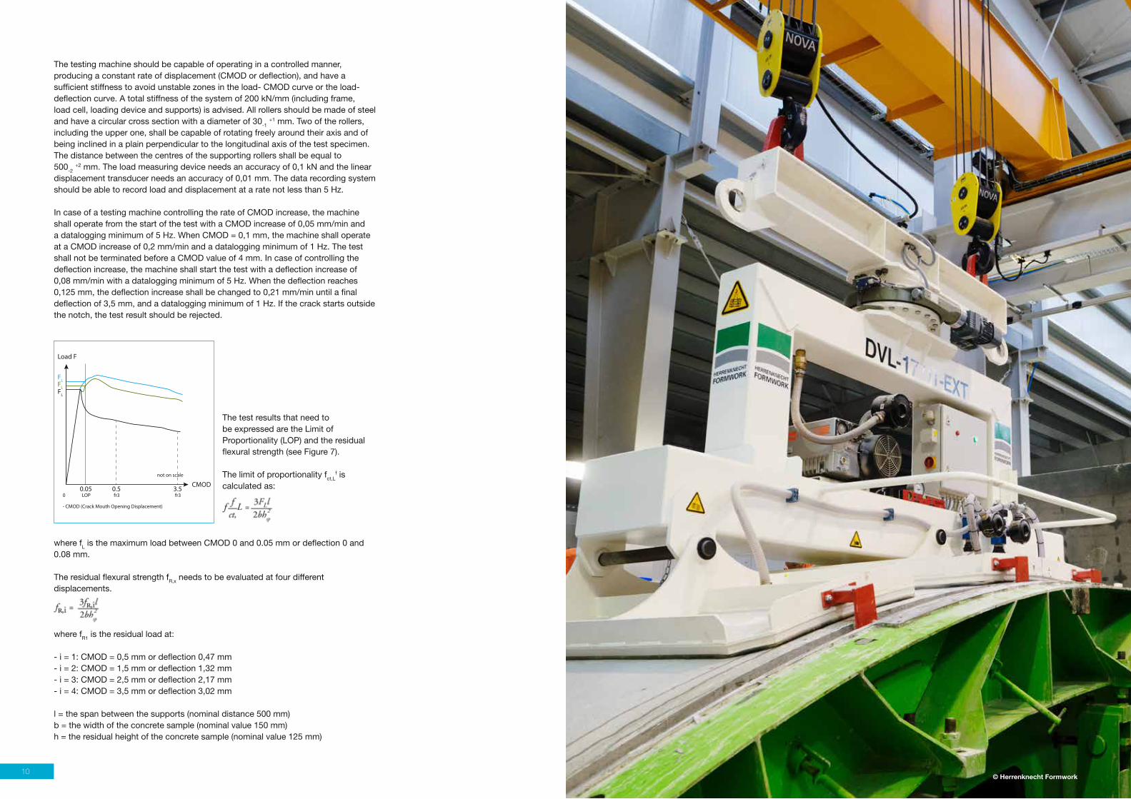
Why SFRC?
Economical Advantages- Increase of productivity, time saving- Reduction of repair cost of damage segments- Elimination of storage and positioning of reinforcement cages- Use of automatic dosing and dispensing equipment linked to the control panel of the batching plant
homogeneousdistribution
steel fibres, present close to the surface, ensure excellent reinforcement at the joints of segments
multidirectionalreinforcement
steel fibres provide a resistance to stress in all directions
increasedload bearingcapacity
steel fibres provide a substantial increase in load capacity to first crack and ultimate load at the joints
high impactresistance
the absorbed energy by the steel fibre reinforced concrete during impact is many times greater than the energy absorption of plain concrete
excellentcontrol ofshrinkagecracks
the high number of steel fibres present in the concrete ensure a good control of shrinkage cracks
Best durabilitysolutionavailable
Several research investigations have shown that the durability of steel fibre reinforced concrete (SFRC) under chloride exposure is superior to the one of steel bar reinforced concrete (RC).
SFRC - Steel Fibre Reinforced Concrete
Automatic dosing equipment
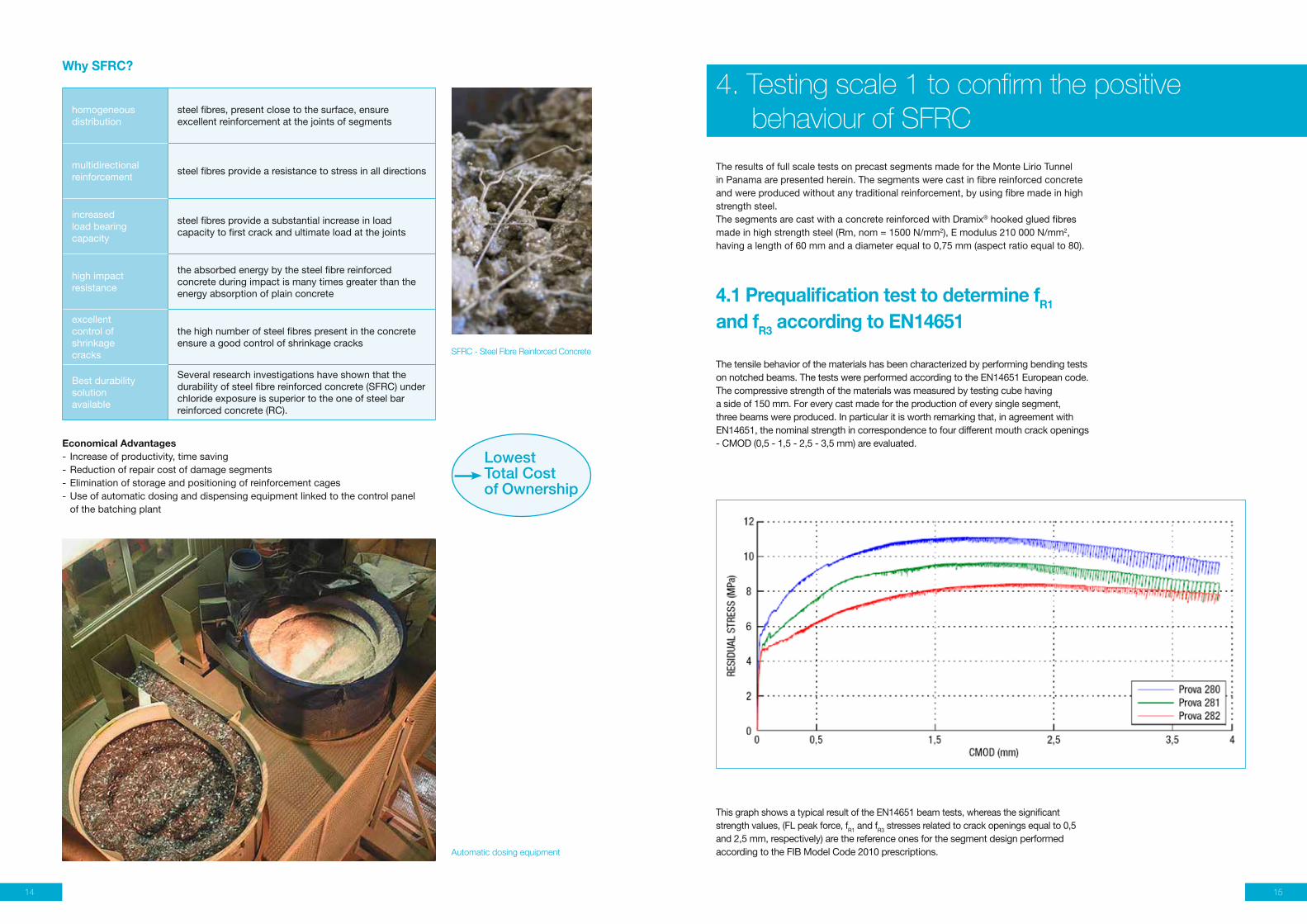
The results of full scale tests on precast segments made for the Monte Lirio Tunnel in Panama are presented herein. The segments were cast in fibre reinforced concrete and were produced without any traditional reinforcement, by using fibre made in high strength steel.The segments are cast with a concrete reinforced with Dramix® hooked glued fibres made in high strength steel (Rm, nom = 1500 N/mm2), E modulus 210 000 N/mm2, having a length of 60 mm and a diameter equal to 0,75 mm (aspect ratio equal to 80).
4.1 Prequalification test to determine fR1 and fR3 according to EN14651
The tensile behavior of the materials has been characterized by performing bending tests on notched beams. The tests were performed according to the EN14651 European code. The compressive strength of the materials was measured by testing cube having a side of 150 mm. For every cast made for the production of every single segment, three beams were produced. In particular it is worth remarking that, in agreement with EN14651, the nominal strength in correspondence to four different mouth crack openings - CMOD (0,5 - 1,5 - 2,5 - 3,5 mm) are evaluated.
4. Testing scale 1 to confirm the positive behaviour of SFRC
This graph shows a typical result of the EN14651 beam tests, whereas the significant strength values, (FL peak force, fR1 and fR3 stresses related to crack openings equal to 0,5 and 2,5 mm, respectively) are the reference ones for the segment design performed according to the FIB Model Code 2010 prescriptions.
LowestTotal Cost of Ownership
14 15
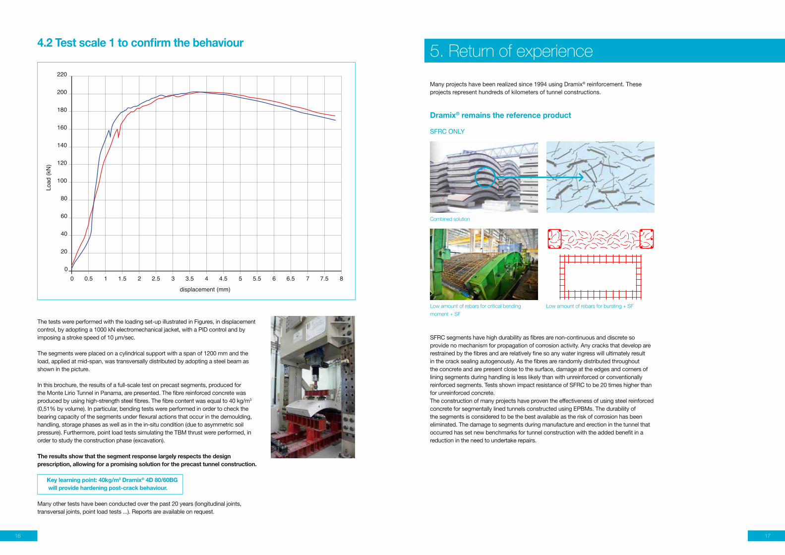
4.2 Test scale 1 to confirm the behaviour
220
200
180
160
140
120
100
80
60
40
20
0
Load
(kN
)
0 0.5 1 1.5 2 2.5 3 3.5 4 4.5 5 5.5 6 6.5 7 7.5 8
displacement (mm)
The tests were performed with the loading set-up illustrated in Figures, in displacement control, by adopting a 1000 kN electromechanical jacket, with a PID control and by imposing a stroke speed of 10 μm/sec.
The segments were placed on a cylindrical support with a span of 1200 mm and the load, applied at mid-span, was transversally distributed by adopting a steel beam as shown in the picture.
In this brochure, the results of a full-scale test on precast segments, produced for the Monte Lirio Tunnel in Panama, are presented. The fibre reinforced concrete was produced by using high-strength steel fibres. The fibre content was equal to 40 kg/m3 (0,51% by volume). In particular, bending tests were performed in order to check the bearing capacity of the segments under flexural actions that occur in the demoulding, handling, storage phases as well as in the in-situ condition (due to asymmetric soil pressure). Furthermore, point load tests simulating the TBM thrust were performed, in order to study the construction phase (excavation).
The results show that the segment response largely respects the design prescription, allowing for a promising solution for the precast tunnel construction.
Key learning point: 40kg/m3 Dramix® 4D 80/60BG will provide hardening post-crack behaviour.
Many other tests have been conducted over the past 20 years (longitudinal joints, transversal joints, point load tests ...). Reports are available on request.
!
Many projects have been realized since 1994 using Dramix® reinforcement. These projects represent hundreds of kilometers of tunnel constructions.
Dramix® remains the reference product
SFRC ONLY
5. Return of experience
SFRC segments have high durability as fibres are non-continuous and discrete so provide no mechanism for propagation of corrosion activity. Any cracks that develop are restrained by the fibres and are relatively fine so any water ingress will ultimately result in the crack sealing autogenously. As the fibres are randomly distributed throughout the concrete and are present close to the surface, damage at the edges and corners of lining segments during handling is less likely than with unreinforced or conventionally reinforced segments. Tests shown impact resistance of SFRC to be 20 times higher than for unreinforced concrete. The construction of many projects have proven the effectiveness of using steel reinforced concrete for segmentally lined tunnels constructed using EPBMs. The durability of the segments is considered to be the best available as the risk of corrosion has been eliminated. The damage to segments during manufacture and erection in the tunnel that occurred has set new benchmarks for tunnel construction with the added benefit in a reduction in the need to undertake repairs.
Combined solution
Low amount of rebars for critical bending
moment + SF
Low amount of rebars for bursting + SF
16 17

Overall damage rate to segments
Manufacturing process Construction process
No. of segmentsmade(N°)
Rejected(%)
Repaired(%)
Minor damage norepair needed
(%)
Minor damagecontrolled repair
(%)
Major repair(N°)
260000 0,8 2,8 2,2 0,3 1
High-quality reinforcement in full partnership
“Due to a close collaboration,
we were able to get the most
economical design combined with
the highest performance possible.”
“We used Dramix® steel fibres to reinforce precast segmental linings for the rail link tunnel between the Channel and St Pancras station in London.
Not only did the fibres significantly improve the handling capacity and surface finish of the segments, Bekaert’s economical design helped us save more than 10% on the estimated installation costs.
Using Dramix®, convinced us that steel fibre reinforced segments are the future intunnel construction.”
6. Design approach
The precast segments have to resist bending moments and flexural stresses when being demoulded and transported to the storage facilities located outside the precast building. They have to resist tensile thermal stresses due to temperature changes at the storage area. The heaviest loading, however, takes place when the segments are being installed and have to resist the very high jack or ram loads of the TBM when moving forward.
The very complex tensile stress pattern induced by these loads requires a quite complicated steel reinforcing cage, which makes it heavy and expensive.
As explained in AFTES (French Tunnelling Association) recommendation “the design, sizing and construction of precast concrete segments installed at the rear of a tunnel boring machine”, it is essential to state that there is no unique design for segmental lining. Very often design is based on the experience and skills acquired by the consulting engineers and contractors on past projects.
6.1 General design of SFRC liningsToday’s experience with fibre reinforced segments is based primarily on a concept of solid linings, in combination with a segment geometry in the form of rectangles + trapezoids, or parallelograms + trapezoids, or trapezoids.The same precautions as for concrete segments should be applied with regards to the contact surfaces, by devoting particular care to the clearance of the angles of the contact areas of the faces between segments and between rings.The actual contact surface shall be taken into account for the forces to be transmitted and for the localized forces (ram pads of the tunnel boring machine). The provisions for the packing seals are identical to those for the concrete segments.
6.2 Assembly devicesSpecial attention must be paid to the design of the assembly devices, which must be assessed in close association with the mechanical capacities of the fibre concrete.
Conventional assemblies include:• Mechanical assemblages by screwing (between segments and between rings) - Straight or curved bolts - Inclined anchor bolts• Assemblies by plugs or dowel + stud (between rings)• Assemblies (positioning) by guide bar (between segments)
Assembly or positioning by guide bar, generally a circular rod in plastic, does not require any particular precautions.
Assembly by reservation or dowel + stud may induce radial forces in the case of a press fit. (This is, for example, the case when plastic plugs are inserted directly into a concrete reservation). It is usually shrunk on either by reinforcing the faces, or with an additional turn. Since the radial forces are difficult to quantify, a test can easily be carried out based on a prismatic test specimen representative of the thickness of the segments and a press fitting of the studs to verify the strength of the concrete volume.
Assembly by screwing may prove more delicate with steel fibre reinforced segments; preference should therefore be given to the other methods, which are also increasingly being applied for safety reasons (fewer operator interventions for installing the elements) and for productivity gains in the assembly of the rings.
6.3 Sizing of SFRC segmentsTo identify, as exhaustively as possible, all load conditions that may affect the sizing of SFRC segments, it is useful to refer to the preceding recommendation on the sizing of reinforced concrete segments.When considering the sizing of a segment from an SFRC angle, a reliable technical solution can only be achieved by applying a rigorous procedure. This procedure breaks down into the following steps:
1 Definition of the dimensioning stresses in relation to the tunnel and the segments under consideration.2 With respect to the stresses defined in step 1, sizing of the SFRC segment using the Model code edited by fib in 2010 or the RILEM guideline published in 20033 Execution of pre-qualification tests to verify that the proposed SFRC satisfies the mechanical properties used in the sizing.4 Execution of control tests to monitor the quality of the SFRC used in the manufacturing of the segments. In this altogether conventional procedure, only steps 2, 3, and 4 are specific to SFRC.
Hadyn Davies,
Client Manager Tunnels High Speed 1,
LCR London
Example:
The Channel Tunnel Rail Link (CTRL) is the UK’s first major new railway for over a century – a highspeed line running for 108 km (68 miles) between the Channel Tunnel and St Pancras station in central London. This project was a real breakthrough, with more than 260 000 segments with SFRC only, using 30 kg/m3 Dramix® + 1 kg PP fibre.
Key learning point ➜ Overall damage reduced to a minimum
18 19
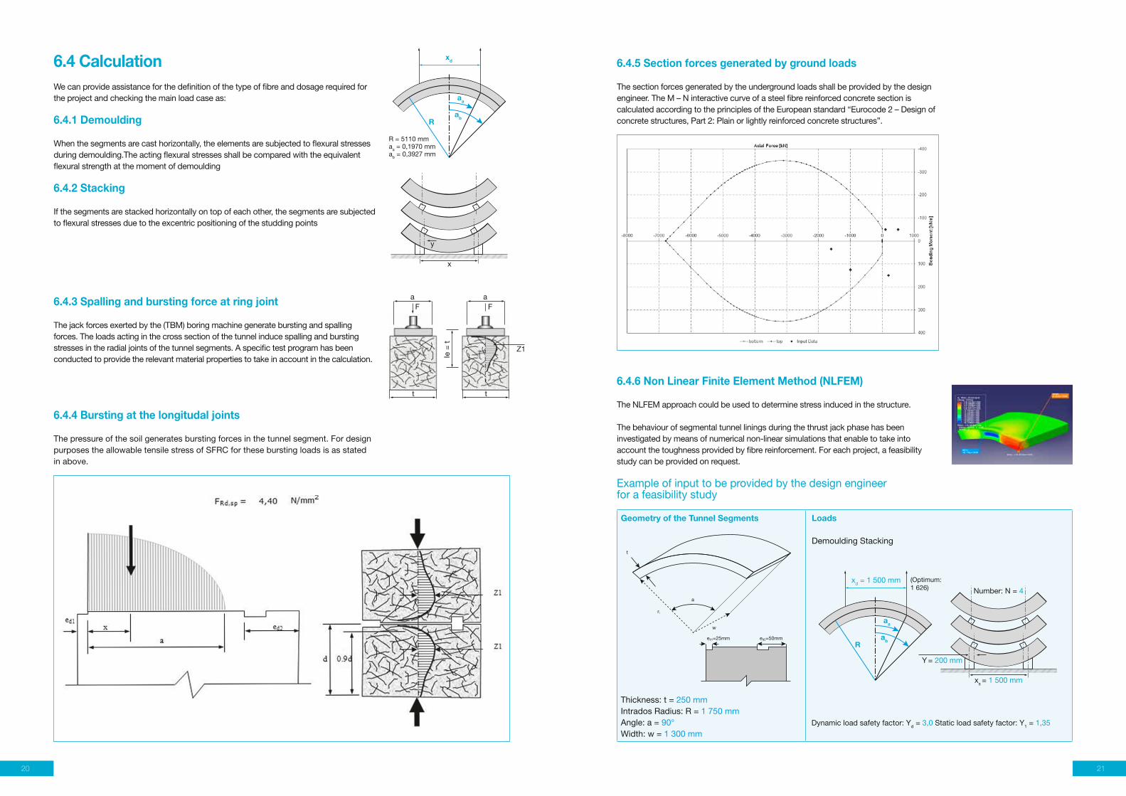
6.4 CalculationWe can provide assistance for the definition of the type of fibre and dosage required for the project and checking the main load case as:
6.4.1 Demoulding
When the segments are cast horizontally, the elements are subjected to flexural stresses during demoulding.The acting flexural stresses shall be compared with the equivalent flexural strength at the moment of demoulding
6.4.2 Stacking
If the segments are stacked horizontally on top of each other, the segments are subjected to flexural stresses due to the excentric positioning of the studding points
6.4.3 Spalling and bursting force at ring joint
The jack forces exerted by the (TBM) boring machine generate bursting and spalling forces. The loads acting in the cross section of the tunnel induce spalling and bursting stresses in the radial joints of the tunnel segments. A specific test program has been conducted to provide the relevant material properties to take in account in the calculation.
6.4.4 Bursting at the longitudal joints
The pressure of the soil generates bursting forces in the tunnel segment. For design purposes the allowable tensile stress of SFRC for these bursting loads is as stated in above.
R
x
y
aa
xd
F F
t
a a
t
Z1
Ie =
t
ab
R = 5110 mmaa = 0,1970 mmab = 0,3927 mm
6.4.5 Section forces generated by ground loads
The section forces generated by the underground loads shall be provided by the design engineer. The M – N interactive curve of a steel fibre reinforced concrete section is calculated according to the principles of the European standard “Eurocode 2 – Design of concrete structures, Part 2: Plain or lightly reinforced concrete structures”.
6.4.6 Non Linear Finite Element Method (NLFEM)
The NLFEM approach could be used to determine stress induced in the structure.
The behaviour of segmental tunnel linings during the thrust jack phase has been investigated by means of numerical non-linear simulations that enable to take intoaccount the toughness provided by fibre reinforcement. For each project, a feasibility study can be provided on request.
Example of input to be provided by the design engineer for a feasibility study
Geometry of the Tunnel Segments
Thickness: t = 250 mmIntrados Radius: R = 1 750 mmAngle: a = 90°Width: w = 1 300 mm
Loads
Demoulding Stacking
Dynamic load safety factor: Yd = 3,0 Static load safety factor: Y1 = 1,35
R
aa
xd = 1 500 mm (Optimum:1 626)
ab
xs = 1 500 mm
Number: N = 4
Y = 200 mm
a
w
ri
ed1=25mm ed2=50mm
t
a
w
ri
ed1=25mm ed2=50mm
t
20 21

Material Characteristics
ConcreteIn-service compressive strenght fck = 60 MPaStripping compressive strenght fc.str = 20 MPaStacking compressive strenght fc.stk = 25 MPa
Fibre type Dramix® 4D 80/60BGPerformance class 80Length 60 mmDiameter 0,75 mmDosage 30 kg/m3
Steel Fibre Reinforced ConcretePost crack mean flexural strength FR4,m = 4,52 MPaMaterial safety factor: YM = 1,5
Steel reinforcementdesign steel strength: fy = 435 MPaAs1: diameter = 14 mmpitch = 90 mm
TBM Characteristics
Maximum push of TBM F1 = 21 237 kNNumber of rams n° = 10 kN Jack force safety factor: Yf = 1,25Width of ram shoe a = 150 mmLength of ram shoe 5 = 519 mm
Section Forces Generated by Ground Loads
Service Loads Accidental Loads
Load Case N (kN/m) M (kNm/m) N (kN/m) M (kNm/m)
0+8001+7002+9003+7006+3006+900
Unrest raineUn+Water
-882-4,334-2,740-2,467-2,747-2,973-153
-1,882
-30,5-54,3-13,3-100,2-41,1-14,3-68,1-83,2
-1,242-4,963-3,279-2,816-3,188-3,239-519
-2,240
47,2-75,130,4
-119,9-57,6-35,8109,0112,1
Type of fibre Application Product family Concrete mix Dosage kg/m3
4D 80/60BG Precast segment
Glued + L/D>80+hightensile strengthHardening post crack behaviour
5MPA<LOP<8MPA 30-50
Standard proposal SFRC only
Dramix® 4D 80/60BG is specifically designed for precast segments
7. Durability
8. Fire Protection
Dramix® steel fibres can be seen as a proven technology to create durable solutions.
Two different cases are to be considered when analyzing the corrosion of metallic fibres and their behaviour:
• The fibre does not cross a crack emerging on the surface. Apart from some staining that could affect the appearance of the structures, fibre corrosion does not lead to any serious problems for the durability or the bearing capacity of these structures in SFRC.
• The fibre crosses a crack emerging on the surface. The bearing capacity of the SFRC is not significantly affected by crack openings of 250 μm and less.
It has to be underlined that the problem of stains, as referred to above, can be almost entirely eliminated by:• Optimizing the SFRC formulation. These mixes are then sufficiently rich in cement paste to avoid any fibres cropping out on the surface.• Using metallic fibres which enchance the corrosion resistance, such as Dramix® Green Please request our specific product data sheet.
Fire resistance tests on SFRC segments have recently been carried out in Europe. They showed that metallic fibres are an improvement over reinforced concrete, which, due to the thermal conductivity of the reinforcements, causes rapid bursting of the exposed concrete. Splintering, although unavoidable, is limited as compared to reinforced concrete.
Just as with conventional concrete segments, the addition of polypropylene microfibres to the composition of the SFRC considerably reduces the risk of splintering.
The combination of metallic fibres and polypropylene microfibres therefore constitutes an adequate solution for improved fire resistance.
The Channel Tunnel Rail Link (CTRL) is a major new railway for over a century - a high-speed line running for 108 km (68 miles) between the Channel Tunnel and central London. The project includes over 40 kilometres of 7,15 meter diameter, precast concrete lined bored tunnels, sections of which are to be constructed in water bearing sand.
An important test program was conducted to evaluate different mix with monofilament and fibrillated polypropylene fibre.
Main point of conclusion“The inclusion of 1 kg/m3 of monofilament polypropylene fibres in the high strength, low permeability mixes tests significantly reduced the risk of explosive spalling when exposed to the severe hydrocarbon fibres.”
Our proposal for fire resistance:PP fibre type• Tensile strength = RM NOM ≥ 250 N/mm2
• Melting point: 165°C• Density < 950 kg/m2
• E module ≥ 3 500 N/mm2
• Length: 5mm - 7 mm - Diameter < 20 μm (recommended) - Dosage: 1 kg to 1,5 kg/m3
The main benefits of pp for fire resistance concluded for monofilament, short and thin fibres as Duomix® M6 Fire.
Galvanized fibreFor certain types of structures, the use of galvanised fibres may avoid the risk of fibre corrosion at the surface.
Galvanized fibres improve long term durability in chloride environment.
The galvanized steel fibres shall be produced from hot galvanized steel wires. The specifications of the zinc coating must comply with (see EN14889-1) classification type B with a minimum zinc coating of 30 g/m2.
The galvanized steel fibres must be protected by an inhibitor, which allows to control and prevent the zinc/cement reaction, and also ensures adhesion of the zinc coating and bonding of the fibres in the concrete matrix.
Without pp fibre With pp fibre
Duomix® Fire (M6), the monofilament
fibre with diameters of less than
20 μm and a length of 6 mm.
22 23

AFTES
Recommendation for “the design, sizing and
construction of precast concrete segments
installed at the rear of a tunnel boring machine
(TBM) and AITES Guideline”.
RILEM-Committee-TDF-162,
Chairlady L. Vandewalle, main author Stang,
H: “Test and Design Methods for Steel Fibre
Reinforced Concrete Design of Steel Fibre
Reinforced Concrete using the s/w Method:
Principles and Applications.” Materials and
Structures, 35, 249, 262-278, 2002.
Code Model Draft - Fib Bulletins 55-56:
Model Code 2010
First complete draft. 2010.
Brite-Euram Project
sub-task Durability
Focusing on Fibres:
CTRL Experience - Tunnels & Tunnelling Int
March 2006
EN14651
“Test method for metallic fibered concrete”.
Measuring
the flexural tensile strength (limit of
proportionality (LOP), residual)
EN14889-1
Fibres for concrete - Part 1: steel fibres -
Definitions, specifications and conformity
Tests on precast tunnel segment of the Monte
Lirio (Panama) tunnel University Roma Universita’
Di Roma “Tor Vergata” Dipartimento di ingegneria
civile laboratorio di strutture e prove materiali
The consultant’s view on service life design
COWI
Quality Assurance Guidelines for use of Steel
Fiber Reinforced Concrete (SFRC)
Brtite Euram Project
Steel fibre reinforcement for tunnels under
severe geological conditions
Suter R., buchs P., Lisbon IABSE LISBON 2005
State of the art segmental lining Lee Tunnel
Tunnelling Journal International
Steel fibre Tunnel lining
Eddie woods - ARUP - RETC Proceeding
Design and uses SFRC segments
M.King - Halcrow - RETC Proceeding
Lining design fro the district heating tunnel
in Copenhagen with steel fibre reinforced
concrete segments
Carola Edvarsen Cowi - Science direct
novembre 2007
ITA WG2
Twenty years of FRC experience and practice
“Lessons Learned and design principle
ACI 544
Technology Report on Design and Construction
of Fibre-Reinforced Precast Concrete Tunnel
Segments.
ISO 13270
Steel Fibres for Concrete - Definition &
Specifications
11. Bibliography9. Green solution
10. Main points of specification
1 Using less steel for the same strength compared to rebar2 Using at least 20% recycled steel in the production process3 Producing in ISO 14001 certified plants4 Creating green products5 Allowing to build durable structures
10.1. Fibres• Fibres should comply with the European Standard EN14889-1 and ISO 13270.• Fibres with CE marking, system 1 (Fibres for structural use) - Fibres out of drawn wire, with a tensile strength of the steel wire ≥ 1 500 MPa - Dimensional tolerances according to EN14889-1 and the new ISO 13270 standard for steel fibre - Fibre length: 50 or 60 mm - l/d ratio 80 is recommended - Galvanized min. 30 g/m²
Based on our experience we recommend for this application a fibre with the following minimum material properties:
• Tensile strength: Rm,nom: 1 800 N/mm2
• Young’s Modulus: ± 210 000 N/mm• Geometry: length = 60 mm and diameter = 0,75 mm
Comparison Rebar / mesh Dramix®
Conrete Precast segment L/D >65
Energy consumption (GJ/m3) 2,89 2,89
Reinforcement
Reinforcement (kg/m3) 100 40
Type mesh 4D 80/60BG
Energy consumption (GJ/ton) 22,5 22,5
Reduction of energy consumption (GJ/m³) 5,14 3,79
Reinforcement 26%
Dramix® steel fibres, used to reinforce concrete constructions, allow for a reduction in the energy consumed per cubic meter of concrete, by 26%, when compared to the classical steel rebar solution.
The Dramix® 4D series is designed with optimal serviceability and performance in mind. Its tensile strength and anchorage are engineered specifically to be used in high strength concrete. The high tensile strength of 1 800 N/mm2, in combination with the special 4D end hook makes this fibre ideal for concrete classes used in precast segments. High strength concrete + high tensile wire + optimised 4D hook give exceptional post crack behaviour.Dramix® 4D 80/60BG will be the cost effective solution for the future precast tunnel segment. Nevertheless, in order to obtain the desired results, it is worth noting the necessity to develop an accurate study of the material, i.e. the fibre typology suitable to a peculiar matrix.
10.2. Fibre Concrete• Glued fibres to ensure a good distribution and homogeneity in the concrete. • Steel fibres have to be added by an automatic dosing system• Type of concrete: C50/60
10.3. Performance10.3.1 Minimum overlap according to McKee Theory
Minimum dosages of steel fibres based on different aspect ratios & steel fibre spacing.
10.3.2 Method of characterization – pre-construction test:Min. average residual flexural strength is measured with standard EN14651 “Test method for metallic fibered concrete - Measuring the flexural tensile strength (limit of proportionality (LOP), residual)”.fR1 is the residual flexural tensile strength corresponding with CMOD = 0,5 mmfR3 is the residual flexural tensile strength corresponding with CMOD = 2,5 mm A minimum characteristic value fR1 and fR3 should be indicated according to the performance required by the project A minimum ratio fR1/fR2 should be indicated > 0,9
Aspect ratio (lf/df=A) 50 55 60 65 80
Overlap factor = 1,66 : min dosage (kg/m3) >50 48 40 35 22
Overlap factor = 2,0 : min dosage (kg/m3) >80 80 67 58 38
24 25

12. Reference Project Overview: Segmental Lining
Ferrovia Circumetnea Catania Rail Sicily, Italy
Sanierungstunnel Belchen Road Switzerland
Dugway Storage Tunnel - Cleveland, OH Sewage USA
DC Water Projects Sewage Washington DC
Bright Water Sewer System, Phase 2 Sewage King County
LA Water River Supply Conduit - 5&6 Hydro Hollywood
Central Subway Line Metro San Francisco
Evergreen LRT Line Metro Vancouver
Green Line, Doha Metro Qatar
Red Line South Doha Metro Qatar
Shieldhall Tunnel Sewage UK
Quito Metro Ecuador
Northern Line Extension Metro UK
Perth Airport Link Rail Australia
Thomson Line T207 Metro Singapore
STEPAbu Dhabi Sewage UAE
Klang Valley MRT - SBK Line Metro Malaysia
Follo Line Oslo Rail Norway
This overview shows only some of our globally spread projects, a large & detailed reference list is available upon request: [email protected]
26 27

Contact us:Bekaert Maccaferri Underground Solutions BVBASkylinE40 – Korte Keppestraat 23/02 – 9320 Aalst-Erembodegem – Belgium
[email protected] +32 53 43 10 10 – F +32 53 43 10 19
www.bm-underground.com Des
ign
by G
roup
Van
Dam
me
& p
rint b
y P
ureP
rint E
U_E
ng_v
1
Benefit from our full service
24
531For the concrete mix design, we take into account all relevant
standards, as well as the specific load bearing requirements of your tunnel project. This will result in a specific steel fibre dosage tailored to your project, which guarantees the most economical and qualitative result.
Dramix® steel fibres are submitted to severe quality control according to international standards, including ISO 9001 and ISO 14001.
On top of the steel fibre quality control, dedicated tests for the entire steel fibre concrete mix are performed in controlled testing laboratories. We have our own concrete lab available to support you.
Thanks to our worldwide network, we are able to offer on-site support virtually anywhere. We also offer dedicated dosing equipment, which allows contractors to save time and work with the highest precision.
Our global experts bundle many years of tunnel construction experience. They closely monitor the latest developments in the field and regularly contribute their knowledge and opinion to the experts’ community.