Embed Size (px)
Citation preview
Hunt &Del Nero, Tunneling in Cobbles and Boulders, Breakthroughs in Tunnelling 2011, CSM 1
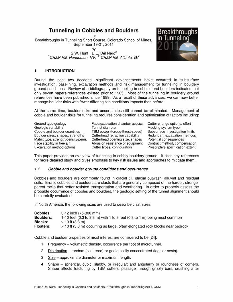
Tunneling in Cobbles and Boulders for
Breakthroughs in Tunneling Short Course, Colorado School of Mines, September 19-21, 2011
by S.W. Hunt
1, D.E. Del Nero
2
1CH2M Hill, Henderson, NV,
2 CH2M Hill, Atlanta, GA
1 INTRODUCTION
During the past two decades, significant advancements have occurred in subsurface investigation, baselining, excavation methods and risk management for tunneling in bouldery ground conditions. Review of a bibliography on tunneling in cobbles and boulders indicates that only seven papers-references existed prior to 1985. Most of the tunneling in bouldery ground references have been published since 1999. As a result of these advances, we can now better manage boulder risks with fewer differing site conditions impacts than before. At the same time, boulder risks and uncertainties still cannot be eliminated. Management of cobble and boulder risks for tunneling requires consideration and optimization of factors including: Ground type-geology Face/excavation chamber access Cutter change options, effort Geologic variability Tunnel diameter Mucking system type Cobble and boulder quantities TBM power (torque-thrust-speed) Subsurface investigation limits Boulder sizes, shapes, strengths Cutterhead retraction capability Redundant excavation methods Matrix type, strength/density/perm. Cutterhead opening size, shapes Potential consequences Face stability in free air Abrasion resistance of equipment Contract method, compensation Excavation method options Cutter types, configuration Prescriptive specification extent
This paper provides an overview of tunneling in cobbly-bouldery ground. It cites key references for more detailed study and gives emphasis to key risk issues and approaches to mitigate them.
1.1 Cobble and boulder ground conditions and occurrence
Cobbles and boulders are commonly found in glacial till, glacial outwash, alluvial and residual soils. Erratic cobbles and boulders are clasts that are generally composed of the harder, stronger parent rocks that better resisted transportation and weathering. In order to properly assess the probable occurrence of cobbles and boulders, the geologic setting of the tunnel alignment should be carefully evaluated. In North America, the following sizes are used to describe clast sizes: Cobbles: 3-12 inch (75-300 mm) Boulders: 1-10 feet (0.3 to 3.3 m) with 1 to 3 feet (0.3 to 1 m) being most common Blocks: > 10 ft (3.3 m) Floaters: > 10 ft (3.3 m) occurring as large, often elongated rock blocks near bedrock
Cobble and boulder properties of most interest are considered to be [24]:
1 Frequency – volumetric density, occurrence per foot of microtunnel.
2 Distribution – random (scattered) or geologically concentrated (lags or nests).
3 Size – approximate diameter or maximum length.
4 Shape – spherical, cubic, slabby, or irregular; and angularity or roundness of corners. Shape affects fracturing by TBM cutters, passage through grizzly bars, crushing after
Hunt &Del Nero, Tunneling in Cobbles and Boulders, Breakthroughs in Tunnelling 2011, CSM 2
ingestion and abrasion of the cutters and mucking system. Flatter clasts are generally easier to split than round clasts. Angular clasts are generally more abrasive than rounded clasts.
5 Composition – rock mineralogy, lithology, compressive strength, and degree of weathering all effect fracturing by TBM cutters, energy required for commutation of clasts and abrasion of the cutters and mucking system. Mineral grain size, fabric, crystal arrangement, foliation and sedimentary sub-bedding also generally affect the energy required for splitting and crushing as well as abrasiveness of the clasts.
6 Abrasiveness – Abrasiveness of the ground and wear to cutters, cutterhead, crushers, chamber and mucking system increases as the percentage of hard minerals in matrix soil and clasts encountered increases. Abrasiveness can be estimated from the relative percentage of minerals of different Moh’s hardness classes and by tests on both the clasts and soil matrix. Angularity of the clasts also increases abrasiveness.
7 Matrix soil composition – density, strength, grain-size distribution, and permeability affect ease of dislodgement by cutters, disc cutter effectiveness, ability to push boulders aside, and stand-up time or ground improvement required for manual drilling and splitting.
Cobbles and boulders may be isolated and scattered or in small to large clusters (nests) or lag zones. Cobble and boulder clusters are more common along eroded geologic contacts, within talus and near the bedrock surface. Careful determination of the geologic setting is essential for proper assessment of likely cobble and boulder concentrations and distribution.
1.1. Geologic Setting
The distribution, quantities and properties of cobbles and boulders within a soil unit should be assessed in conjunction with the geology of the formations involved. Baselining of boulders based on soil type, e.g. silty clay or gravelly sand, may not result in reasonable correlations. Instead, boulder occurrence should be assessed for individual geologic soil units with consideration of common geologic characteristics and anomalies. The importance of using a geologic framework when assessing boulder occurrence (and other ground conditions that affect tunneling) has been explained by many authors: Essex (1993), Gould (1995), Heuer (1978), Legget (1979), Hunt & Angulo (1999) and others [14][21][22][24][33]. Typical characteristics of boulders and likelihood of occurrence within various glacial units and morphological features are discussed in many geology books. If available, local geologic papers and publications should be studied to better understand the regional structure and typical characteristics of the units and formations that are likely to be encountered. Boulder occurrence can be better understood and baselined if the subsurface exploration data is presented in a geologic context.
1.1. Boulder Volume Ratio
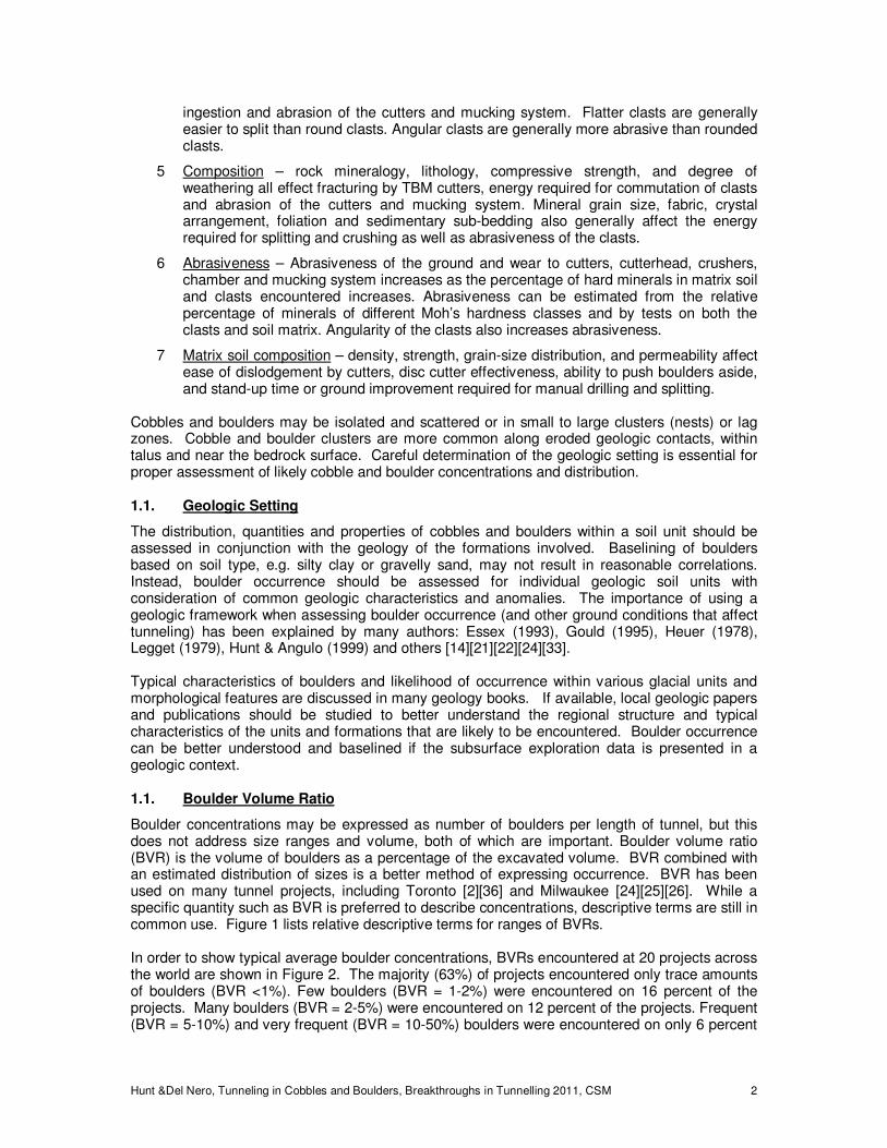
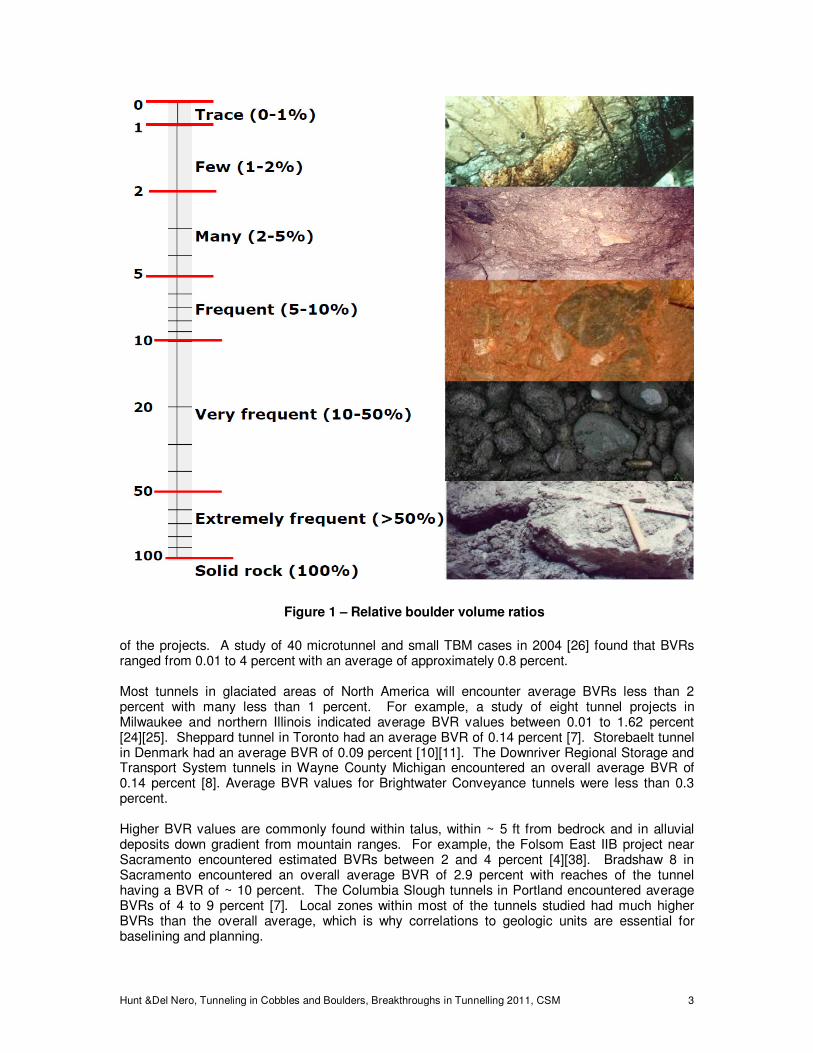
Boulder concentrations may be expressed as number of boulders per length of tunnel, but this does not address size ranges and volume, both of which are important. Boulder volume ratio (BVR) is the volume of boulders as a percentage of the excavated volume. BVR combined with an estimated distribution of sizes is a better method of expressing occurrence. BVR has been used on many tunnel projects, including Toronto [2][36] and Milwaukee [24][25][26]. While a specific quantity such as BVR is preferred to describe concentrations, descriptive terms are still in common use. Figure 1 lists relative descriptive terms for ranges of BVRs. In order to show typical average boulder concentrations, BVRs encountered at 20 projects across the world are shown in Figure 2. The majority (63%) of projects encountered only trace amounts of boulders (BVR <1%). Few boulders (BVR = 1-2%) were encountered on 16 percent of the projects. Many boulders (BVR = 2-5%) were encountered on 12 percent of the projects. Frequent (BVR = 5-10%) and very frequent (BVR = 10-50%) boulders were encountered on only 6 percent
Hunt &Del Nero, Tunneling in Cobbles and Boulders, Breakthroughs in Tunnelling 2011, CSM 3
of the projects. A study of 40 microtunnel and small TBM cases in 2004 [26] found that BVRs ranged from 0.01 to 4 percent with an average of approximately 0.8 percent. Most tunnels in glaciated areas of North America will encounter average BVRs less than 2 percent with many less than 1 percent. For example, a study of eight tunnel projects in Milwaukee and northern Illinois indicated average BVR values between 0.01 to 1.62 percent [24][25]. Sheppard tunnel in Toronto had an average BVR of 0.14 percent [7]. Storebaelt tunnel in Denmark had an average BVR of 0.09 percent [10][11]. The Downriver Regional Storage and Transport System tunnels in Wayne County Michigan encountered an overall average BVR of 0.14 percent [8]. Average BVR values for Brightwater Conveyance tunnels were less than 0.3 percent. Higher BVR values are commonly found within talus, within ~ 5 ft from bedrock and in alluvial deposits down gradient from mountain ranges. For example, the Folsom East IIB project near Sacramento encountered estimated BVRs between 2 and 4 percent [4][38]. Bradshaw 8 in Sacramento encountered an overall average BVR of 2.9 percent with reaches of the tunnel having a BVR of ~ 10 percent. The Columbia Slough tunnels in Portland encountered average BVRs of 4 to 9 percent [7]. Local zones within most of the tunnels studied had much higher BVRs than the overall average, which is why correlations to geologic units are essential for baselining and planning.
Figure 1 – Relative boulder volume ratios
Hunt &Del Nero, Tunneling in Cobbles and Boulders, Breakthroughs in Tunnelling 2011, CSM 4
Cobble quantities and volume ratios are generally higher than those for boulders. In Milwaukee, cobble volume ratios were estimated to be approximately 1.5 to 2 times the BVRs which resulted in much higher cobble quantities due to their smaller sizes. In Sacramento, the cobble volume ratios were much greater due to fluvial sorting and typically ranged from 5 to 10 times greater than the BVRs. In Columbus, 157,021 cobbles and 5,429 boulders were estimated for 20,770 ft of 14 ft diameter tunnel [17]. A back analysis by S. Hunt indicated an approximate cobble volume ratio (CVR) of 0.22% and a BVR of 0.34% - the CVR may have been underestimated or the BVR overestimated (the latter according to the contractor [8]). In summary, quantities and frequencies of cobbles and boulders are highly variable and dependent on geologic conditions. Methods for investigating quantities and baselining boulders are discussed later in this paper.
1.2 Cobble and boulder risks, hazards and potential consequences
A comprehensive risk management program is essential to properly manage boulder risks for tunneling. Boulder risks can be evaluated within four broad categories:
• Subsurface conditions – ground, groundwater permeability and head, depth. • Construction equipment – tunnel boring machine, mucking system, etc.
• Facility constraints – line and grade limits, drive lengths, settlement sensitivity, etc.
• Contractual – risk sharing, compensation, schedule, etc.
A successful tunneling project requires optimization of all four categories. Cobble and boulder condition risks are many, but concentration and location are of utmost importance. Concentrated cobbles and boulders in lag zones or nests are much more difficult to excavate than isolated cobbles and boulders. Concentrations may choke a microtunnel boring machine (MTBM) or TBM excavation chamber causing the cutterhead torque to become excessive and the MTBM or TBM to stall. Cobble and boulder concentrations may also form a mixed-face condition and may cause steering problems [20].
Figure 2 – Boulder volume ratios from 20 cases
Hunt &Del Nero, Tunneling in Cobbles and Boulders, Breakthroughs in Tunnelling 2011, CSM 5
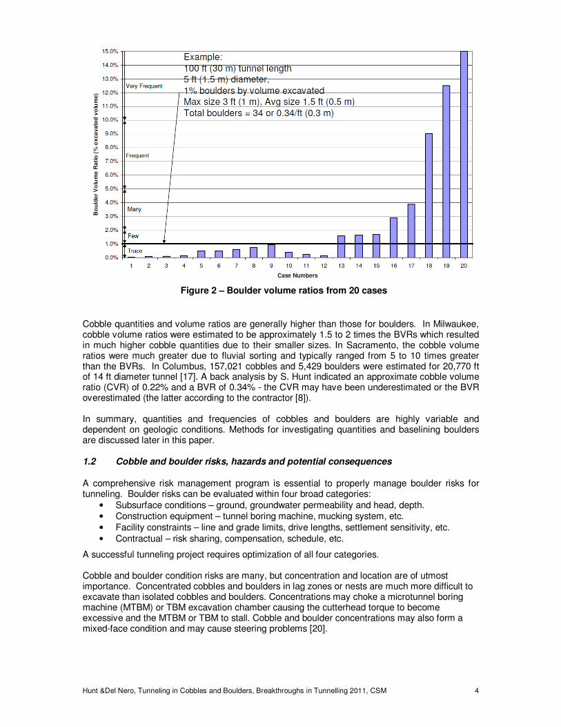
The location of boulders is another factor. Boulders, particularly large ones that extend past the perimeter are much more difficult to cut and more likely to be plucked or pushed. Uncut pushed or partially cut boulders may obstruct or deflect a TBM shield and may damage trailing pipe or a segment lining by point loading (high contact stress) [28]. Table 1 provides a summary of potential hazards related to cobbly-bouldery ground and potential consequences. Table 1 – Boulder encounter hazards and potential consequences
Hazard or Condition Potential consequence
Boulder(s) over ~ 20-30% diameter, no face-chamber access or disc cutters
Stuck MTBM, rescue shaft or shaft-tunnel required or MTBM-tunnel abandoned
Boulders composed of much harder, stronger rock than expected
Severe pump and slurry line wear resulting in pump failure or line rupture
Cobble and boulder quantities much greater than expected
Severe cutter wear, higher tool replacement cost, potential stuck MTBM
Ground is much more abrasive than anticipated
Severe intake port wear resulting in enlarged holes, jammed slurry lines
Boulders in weak-loose matrix resulting in plucked boulder rolling on cutterhead
Severe cutterhead wear or rock crusher bar wear, reduced advance rate, stuck
Mixed face heading weak soil zone adjacent to hard bouldery ground
Steering difficulty, MTBM/TBM deflected beyond line or grade limits
Advance rate higher than allowed for disc cutters causing plucked rock
Broken cutters or cutter housings and/or cutter arms from high impact forces
Attempt to blast or split boulders at heading in free air and unstable soil
Voids, excess lost ground, sinkholes, damaging settlements
Perimeter boulder(s) not cut by gage cutters or plucked from perimeter
Pipe or lining damage from passed perimeter boulder contact stresses
Large oblong boulders pass through cutterhead opening
Boulders jam inside rock crusher
Contractual risk almost always involves advance rates, schedule and ultimately cost. Cobbles and boulders encountered during tunneling almost always increases tunneling cost. Cobbles and boulders generally reduce advance rates [1][4][5][7][9][13][25][26][32][42][43]. Higher tunneling costs result from:
• More expensive TBM equipment requirements • Slower TBM advance rates
• Delays to remove boulder obstructions
• Cost of rescue shafts and tunnels • Delays to repair abrasion damage
• Costs to repair worn or damaged cutters, cutterhead, rock crusher or mucking system
• Higher project risk Higher tunneling costs may result from: higher bid prices, unit rate bid items for boulders or boulder obstructions encountered or as compensation for differing site condition claims.
1.3 Compensation for tunneling in cobbles and boulders
Since tunneling through cobbly-bouldery ground costs more than tunneling through soil without boulders, an important question is how best to properly compensate contractors for tunneling through cobbly-bouldery ground. This topic was addressed in a 2002 paper by Hunt entitled Compensation for Boulder Obstructions [25]. Compensation (pay item) for boulder removal is viable and should be considered when:
• Open face tunneling in stable ground with a manual splitting option;
Hunt &Del Nero, Tunneling in Cobbles and Boulders, Breakthroughs in Tunnelling 2011, CSM 6
• For large boulders or cobble-boulder concentrations that “obstruct” TBM advance as defined in the specifications; and
• When boulder quantities and sizes can be measured. For most other conditions, separate compensation is not practical and the cost of cobble and boulder excavation is generally incidental and paid as part of the unit rate for tunneling. This is particularly true when using a pressurized face TBM that fractures and ingests rock fragments with no reasonable ability to measure quantities or sizes. Making boulder excavation incidental is also appropriate for just about any tunneling method where the BVR is less than 1 percent, maximum boulder sizes are expected to be less than about 25 percent of the excavated diameter and the TBM is equipped with appropriate cutters and face access. Even if the vast majority of cobble and boulders can be fractured and ingested into the mucking system and are considered incidental, a compensation method for obstruction due to nested cobbles and boulders and large boulders should be considered. Experience indicates that paying for defined obstructions as bid is more cost effective than paying for them as part of a differing site condition claim. Two methods of compensation for cobble-boulder obstructions are most common. One method is to bid a unit price per obstruction. This might vary with ranges of boulder obstruction size, face access from the tunnel, tunnel depth and rescue shaft restrictions. Another method is to bid a unit rate for delay time to access and remove qualifying cobble and boulder obstructions. An estimate of total obstruction hours would be baselined in a Geotechnical Baseline Report (GBR) and listed as a pay item quantity in the contract. Either way, what constitutes a qualifying boulder size and boulder obstruction and how it would be measured in the field must be carefully defined. Experience has shown that the removal time method is generally more equitable if face access is available – it reduces contractor risk resulting in better bid prices than the unit price per obstruction method [25]. The additional cost of tunneling in bouldery ground will be minimized if cobble-boulder risks are properly baselined and managed by TBM-MTBM selection including face access, cutter types and power (torque-thrust).
2 SUBSURFACE INVESTIGATION OF BOULDERY GROUND
A case can be made that cobbles and boulders result in more cost and schedule overruns than any other single geologic condition encounter during soft ground tunneling. To exasperate the situation, tunneling risks and costs typically increase, as the cobble and boulder quantities, size, hardness and frequency of occurrence increase. A focused, boulder sensitive subsurface investigation and proper baselining are essential information to communicate to the contractor to enhance tunnel risk mitigation [27]. The basic problem faced by a designer in attempting to predict the geological and geotechnical risks (and costs) during construction of a tunnel is the adequacy of the information obtained from the site investigation program. Many subsurface investigation programs fail to collect sufficient cobble and boulder data resulting in inaccurate information or insufficient data to establish a baseline.
2.1 Effectiveness of Available Methods
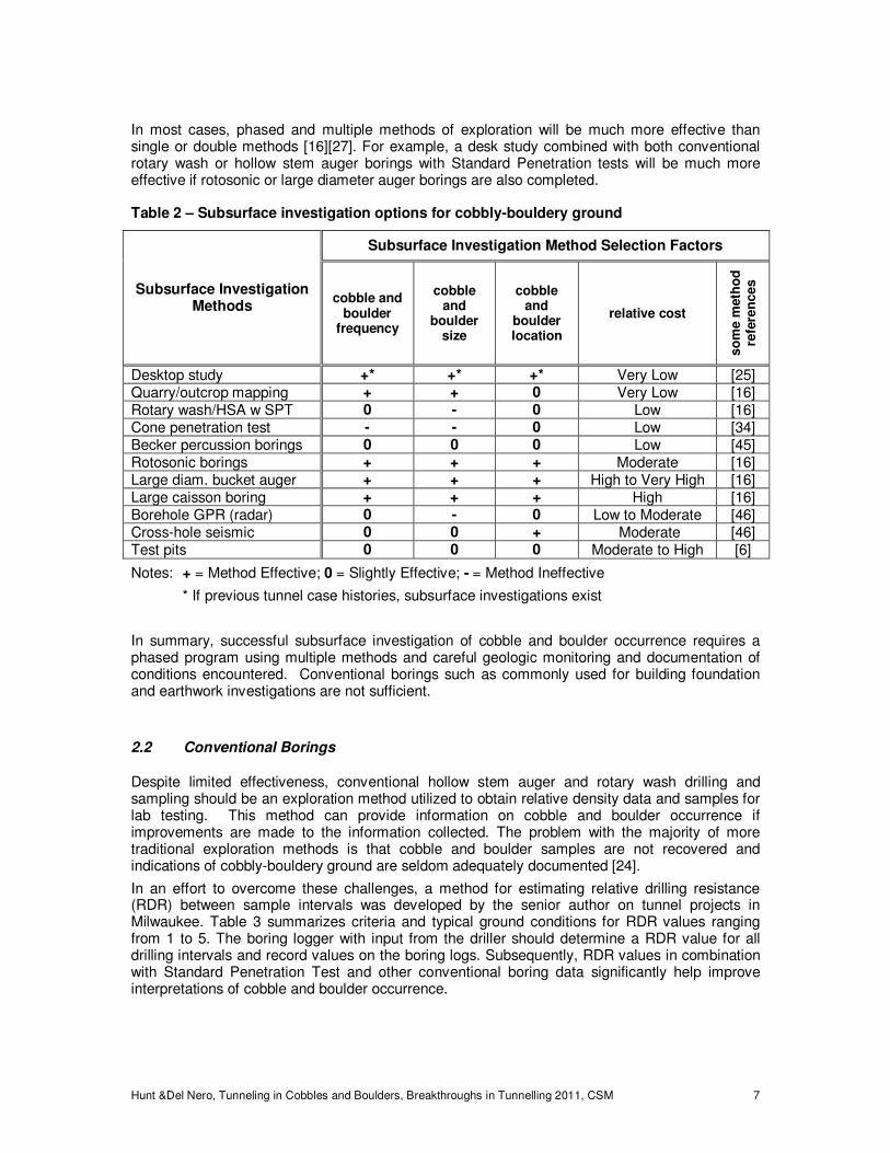
Several authors have presented thorough discussions on the challenges of developing a subsurface investigation scope that is appropriate for cobble and boulder laden ground [14][16][22][24][27][34]. In an effort to synthesize the recommendations made in these papers and provide an update on the latest approaches to cobble and boulder detection in a subsurface investigation, Table 2 was developed. The methods identified in this table are key considerations in an appropriate subsurface investigation program for cobbly-bouldery ground. Some of the methods are limited by available previous data and depths. Test pits are seldom cost effective at depths over about 15-20 feet. Large diameter auger borings are much more difficult and expense below the water table in cohesionless ground and at depths over approximately 50 feet.
Hunt &Del Nero, Tunneling in Cobbles and Boulders, Breakthroughs in Tunnelling 2011, CSM 7
In most cases, phased and multiple methods of exploration will be much more effective than single or double methods [16][27]. For example, a desk study combined with both conventional rotary wash or hollow stem auger borings with Standard Penetration tests will be much more effective if rotosonic or large diameter auger borings are also completed. Table 2 – Subsurface investigation options for cobbly-bouldery ground
Subsurface Investigation Methods
Subsurface Investigation Method Selection Factors
cobble and boulder
frequency
cobble and
boulder size
cobble and
boulder location
relative cost
so
me m
eth
od
re
fere
nces
Desktop study +* +* +* Very Low [25] Quarry/outcrop mapping + + 0 Very Low [16] Rotary wash/HSA w SPT 0 - 0 Low [16] Cone penetration test - - 0 Low [34] Becker percussion borings 0 0 0 Low [45] Rotosonic borings + + + Moderate [16] Large diam. bucket auger + + + High to Very High [16] Large caisson boring + + + High [16] Borehole GPR (radar) 0 - 0 Low to Moderate [46] Cross-hole seismic 0 0 + Moderate [46] Test pits 0 0 0 Moderate to High [6]
Notes: + = Method Effective; 0 = Slightly Effective; - = Method Ineffective
* If previous tunnel case histories, subsurface investigations exist
In summary, successful subsurface investigation of cobble and boulder occurrence requires a phased program using multiple methods and careful geologic monitoring and documentation of conditions encountered. Conventional borings such as commonly used for building foundation and earthwork investigations are not sufficient.
2.2 Conventional Borings
Despite limited effectiveness, conventional hollow stem auger and rotary wash drilling and sampling should be an exploration method utilized to obtain relative density data and samples for lab testing. This method can provide information on cobble and boulder occurrence if improvements are made to the information collected. The problem with the majority of more traditional exploration methods is that cobble and boulder samples are not recovered and indications of cobbly-bouldery ground are seldom adequately documented [24].
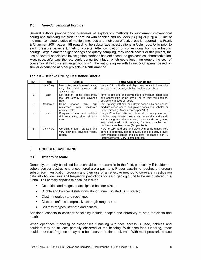
In an effort to overcome these challenges, a method for estimating relative drilling resistance (RDR) between sample intervals was developed by the senior author on tunnel projects in Milwaukee. Table 3 summarizes criteria and typical ground conditions for RDR values ranging from 1 to 5. The boring logger with input from the driller should determine a RDR value for all drilling intervals and record values on the boring logs. Subsequently, RDR values in combination with Standard Penetration Test and other conventional boring data significantly help improve interpretations of cobble and boulder occurrence.
Hunt &Del Nero, Tunneling in Cobbles and Boulders, Breakthroughs in Tunnelling 2011, CSM 8
2.3 Non-Conventional Borings
Several authors provide good overviews of exploration methods to supplement conventional boring and sampling methods for ground with cobbles and boulders [14][16][24][27][34]. One of the most complete studies of multiple methods and their cost effectiveness is reported in a Frank & Chapman 2001 paper [16] regarding the subsurface investigations in Columbus, Ohio prior to earth pressure balance tunneling projects. After completion of conventional borings, rotosonic borings, large diameter auger borings and quarry sampling, they concluded: “For this project, the use of several specialized investigation methods has enhanced the geotechnical characterization. Most successful was the roto-sonic coring technique, which costs less than double the cost of conventional hollow stem auger borings.” The authors agree with Frank & Chapman based on similar experience at other projects in North America.
Table 3 – Relative Drilling Resistance Criteria
RDR Term Criteria Typical Ground Conditions
1 Very Easy No chatter, very little resistance, very fast and steady drill advance rate
Very soft to soft silts and clays; very loose to loose silts and sands; no gravel, cobbles, boulders or rubble
2 Easy No chatter, some resistance, fast and steady drill advance rate
Firm to stiff silts and clays; loose to medium dense silts and sands; little or no gravel, no to very few cobbles, boulders or pieces of rubble
3 Moderate Some chatter, firm drill resistance with moderate advance rate
Stiff to very stiff silts and clays; dense silts and sands; medium dense sands and gravel; occasional cobbles or rubble pieces (2-3 occurrences per 10 ft)
4 Hard Frequent chatter and variable drill resistance, slow advance rate
Very stiff to hard silts and clays with some gravel and cobbles; very dense to extremely dense silts and sands with some gravel; dense to very dense sands and gravel; very weathered, soft bedrock; frequent cobbles and boulders or rubble pieces (3-4 per 10 ft)
5 Very Hard Constant chatter, variable and very slow drill advance, nearly refusal
Hard to very hard silts and clays with some gravel; very dense to extremely dense gravelly sand or sandy gravel; very frequent cobbles and boulders (at least 5 per 10 feet); weathered, very jointed bedrock
3 BOULDER BASELINING
3.1 What to baseline
Generally, properly baselined items should be measurable in the field, particularly if boulders or cobble-boulder obstructions encountered are a pay item. Proper baselining requires a thorough subsurface investigation program and then use of an effective method to correlate investigation data into boulder size and frequency predictions for each geologic unit to be encountered in a tunnel. The primary aspects to baseline include:
• Quantities and ranges of anticipated boulder sizes;
• Cobble and boulder distributions along tunnel (isolated vs clustered);
• Clast mineralogy and rock types;
• Clast unconfined compressive strength ranges; and
• Soil matrix types, strength and density.
Additional aspects to consider baselining include: shapes and abrasivity of both the clasts and matrix. When open-face tunneling or closed-face tunneling with face access is used, cobbles and boulders may be at least partially observed at the heading. With open-face tunneling, intact boulders or rock fragments may also be observed in the muck train. With most pressurized face
Hunt &Del Nero, Tunneling in Cobbles and Boulders, Breakthroughs in Tunnelling 2011, CSM 9
tunneling, the TBM is generally equipped with cutters capable of fracturing boulders to a much smaller size that can pass through the cutterhead and be crushed and ingested into a slurry mucking system or pass through a screw conveyor (auger boring, pilot tube and earth pressure balance systems) into a conveyor belt or rail mucking system. Unless obstructed, generally all of the boulders encountered by a MTBM will be fractured to gravel or smaller sizes making assessment of boulder size and quantity very difficult. Similarly, larger boulders (all but cobbles and small boulders) will be fractured before passing through the mucking system. While intact boulder data is often not available, boulder encounters can be roughly inferred from analysis of penetration rate, torque, cutterhead rotation speed, thrust and angularity of rock fragments. Boulder sizes cannot be reliably determined except for open face tunneling with face access. Distinguishing between cobbles and boulders is also impractical. As a result the limitations given above, a pay item for excavation of all boulders encountered is seldom used and would only be viable for open face tunneling with face access. Pay items are more frequently used to compensate for a defined cobble and boulder obstruction. An example obstruction definition is given below. Obstruction definitions should depend on the owner’s risk sharing position, tunnel size, anticipated tunneling method and cobble and boulder conditions.
A boulder obstruction occurs when a large boulder or cluster of cobbles and boulders is encountered at the heading of a tunnel that stops or significantly inhibits forward progress to less than 10 percent of normal progress for at least 30 minutes under normal thrust and torque with properly functioning cutters, and because boulders are too large or cobbles and boulders are too congested to be broken or ingested through the TBM cutting wheel and tunnel mucking system. In addition, the obstructing boulder or cobbles and boulders require removal by supplementary means such as drilling and splitting from the excavation chamber or removal by an excavation made from outside of the tunnel.
Whether cobbles and boulders or obstructions are a pay item or not, cobble and boulder baselining is still recommended to help bidders determine tunneling methods, estimate advance rates, and estimate cutter wear and replacement costs. Boulder sizes and quantities can be baselined by one or more of three methods:
• Guessing or estimating from past local experience.
• Boulder volume ratio methods. • Use of statistical or probabilistic methods.
Guessing is very risky and not advised. Past local experience is valuable, but must be analyzed with subsurface investigation data that considers geologic settings. The other two methods of boulder baselining are discussed below.
3.2 Boulder volume ratio methods
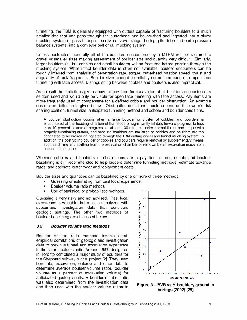
Boulder volume ratio methods involve semi-empirical correlations of geologic and investigation data to previous tunnel and excavation experience in the same geologic units. Around 1997, designers in Toronto completed a major study of boulders for the Sheppard subway tunnel project [2]. They used borehole, excavation, outcrop and other data to determine average boulder volume ratios (boulder volume as a percent of excavation volume) for anticipated geologic units. A boulder number ratio was also determined from the investigation data and then used with the boulder volume ratios to Figure 3 – BVR vs % bouldery ground in
borings (2002) [25]
Hunt &Del Nero, Tunneling in Cobbles and Boulders, Breakthroughs in Tunnelling 2011, CSM 10
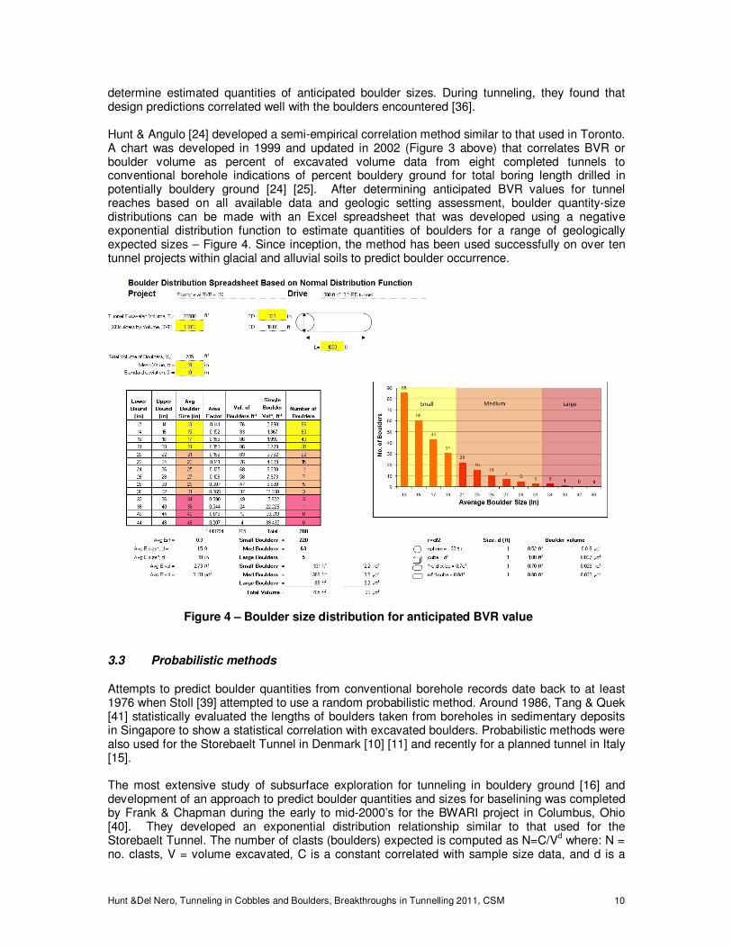
determine estimated quantities of anticipated boulder sizes. During tunneling, they found that design predictions correlated well with the boulders encountered [36]. Hunt & Angulo [24] developed a semi-empirical correlation method similar to that used in Toronto. A chart was developed in 1999 and updated in 2002 (Figure 3 above) that correlates BVR or boulder volume as percent of excavated volume data from eight completed tunnels to conventional borehole indications of percent bouldery ground for total boring length drilled in potentially bouldery ground [24] [25]. After determining anticipated BVR values for tunnel reaches based on all available data and geologic setting assessment, boulder quantity-size distributions can be made with an Excel spreadsheet that was developed using a negative exponential distribution function to estimate quantities of boulders for a range of geologically expected sizes – Figure 4. Since inception, the method has been used successfully on over ten tunnel projects within glacial and alluvial soils to predict boulder occurrence.
3.3 Probabilistic methods
Attempts to predict boulder quantities from conventional borehole records date back to at least 1976 when Stoll [39] attempted to use a random probabilistic method. Around 1986, Tang & Quek [41] statistically evaluated the lengths of boulders taken from boreholes in sedimentary deposits in Singapore to show a statistical correlation with excavated boulders. Probabilistic methods were also used for the Storebaelt Tunnel in Denmark [10] [11] and recently for a planned tunnel in Italy [15]. The most extensive study of subsurface exploration for tunneling in bouldery ground [16] and development of an approach to predict boulder quantities and sizes for baselining was completed by Frank & Chapman during the early to mid-2000’s for the BWARI project in Columbus, Ohio [40]. They developed an exponential distribution relationship similar to that used for the Storebaelt Tunnel. The number of clasts (boulders) expected is computed as N=C/V
d where: N =
no. clasts, V = volume excavated, C is a constant correlated with sample size data, and d is a
Figure 4 – Boulder size distribution for anticipated BVR value
Hunt &Del Nero, Tunneling in Cobbles and Boulders, Breakthroughs in Tunnelling 2011, CSM 11
constant correlated with clast size distribution. The method requires a significant amount of reliable sample data from the subsurface investigation. The constant d is evaluated from boulder sizes found in the investigation. The constant C is calculated from boulder volume data. The number of clasts for selected sizes is then computed using the formula with these constants. Tunneling results indicated that boulder quantities were slightly over-predicted, but accurate estimates of actual boulders encountered were difficult to make from the broken rock and very large quantities of muck [9][40].
3.4 Baselining Recommendations
Which aspects of cobble and boulder conditions to baseline depends on the ground conditions, anticipated methods of construction and project owner’s preferences for risk sharing. The method to use for evaluating data to predict quantities for baselining should depend on the size of the project and the quality and quantity of data available. The boulder volume ratio method is generally more practical than probabilistic methods for most projects. Probabilistic methods are viable for larger projects with a significant amount of quality data. In either case, the method should consider the geologic setting, geologic variability and local experience.
4 TUNNEL EXCAVATION METHODS IN BOULDERY GROUND
4.1 Relative boulder size risk
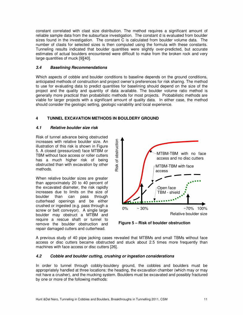
Risk of tunnel advance being obstructed increases with relative boulder size. An illustration of this risk is shown in Figure 5. A closed (pressurized) face MTBM or TBM without face access or roller cutters has a much higher risk of being obstructed than with excavation by other methods. When relative boulder sizes are greater than approximately 20 to 40 percent of the excavated diameter, the risk rapidly increases due to limits on the size of boulder than can pass through cutterhead openings and be either crushed or ingested (e.g. pass through a screw or belt conveyor). A single large boulder may obstruct a MTBM and require a rescue shaft or tunnel to remove the boulder obstruction and repair damaged cutters and cutterhead. A previous study of 40 pipe jacking cases revealed that MTBMs and small TBMs without face access or disc cutters became obstructed and stuck about 2.5 times more frequently than machines with face access or disc cutters [26].
4.2 Cobble and boulder cutting, crushing or ingestion considerations
In order to tunnel through cobbly-bouldery ground, the cobbles and boulders must be appropriately handled at three locations: the heading, the excavation chamber (which may or may not have a crusher), and the mucking system. Boulders must be excavated and possibly fractured by one or more of the following methods:
Ris
k o
f obstr
uct
ion
Relative boulder size
0% ~ 30% ~70% 100%
Figure 5 – Risk of boulder obstruction
MTBM-TBM with no face access and no disc cutters
Open face TBM - shield
MTBM-TBM with face access
Hunt &Del Nero, Tunneling in Cobbles and Boulders, Breakthroughs in Tunnelling 2011, CSM 12
• Plucked from the ground using scrapper and/or roller cutters on a MTBM cutterhead and then passed through the cutterhead into the excavation chamber to be crushed before entering the mucking system.
• Plucked and pushed aside if not passable though cutterhead and matrix is soft or loose enough.
• Fractured and broken using ripper, scrapper and/or roller cutters on a TBM cutterhead before being plucked and passing through the cutterhead to be crushed.
• Accessed from the excavation chamber or from a rescue shaft-tunnel and then manually split or blasted and removed.
• Pushed into a temporary shaft drilled below microtunnel invert at the heading.
Factors that should be considered when selecting the excavation tools and mucking methods include:
• Cobble and boulder strengths, sizes, shapes, distribution and quantities anticipated.
• Type, consistency and strength of the soil matrix with an assessment if sufficient cutting or fracturing is viable before clasts are plucked from the matrix.
• Assessment if the stand-up time of the ground is sufficient to provide safe, free air access to fracture and remove obstructing cobbles and boulders.
• Assessment if ground improvement or compressed air will be required to provide sufficient stand-up time and water control to fracture and remove obstructing cobbles and boulders.
• Settlement damage risk if excess lost ground occurs at the heading.
• Cutter life and cutter cost - disc cutters generally have longer cutter life [35], but are much more expensive [9].
• Energy and associated tool wear required to commutate boulders to gravel or cobble size for passage through a slurry shield mucking system if used, or through screw conveyors if used.
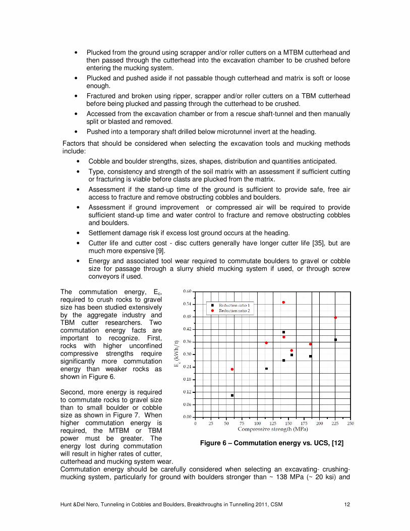
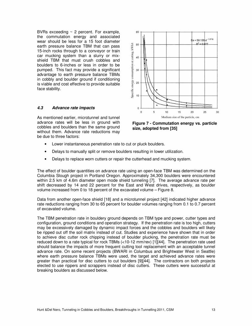
The commutation energy, Ec, required to crush rocks to gravel size has been studied extensively by the aggregate industry and TBM cutter researchers. Two commutation energy facts are important to recognize. First, rocks with higher unconfined compressive strengths require significantly more commutation energy than weaker rocks as shown in Figure 6. Second, more energy is required to commutate rocks to gravel size than to small boulder or cobble size as shown in Figure 7. When higher commutation energy is required, the MTBM or TBM power must be greater. The energy lost during commutation will result in higher rates of cutter, cutterhead and mucking system wear. Commutation energy should be carefully considered when selecting an excavating- crushing-mucking system, particularly for ground with boulders stronger than ~ 138 MPa (~ 20 ksi) and
Figure 6 – Commutation energy vs. UCS, [12]
Hunt &Del Nero, Tunneling in Cobbles and Boulders, Breakthroughs in Tunnelling 2011, CSM 13
BVRs exceeding ~ 2 percent. For example, the commutation energy and associated wear should be less for a 15 foot diameter earth pressure balance TBM that can pass 15-inch rocks through to a conveyor or train car mucking system than a slurry or mix-shield TBM that must crush cobbles and boulders to 6-inches or less in order to be pumped. This fact may provide a significant advantage to earth pressure balance TBMs in cobbly and boulder ground if conditioning is viable and cost effective to provide suitable face stability.
4.3 Advance rate impacts
As mentioned earlier, microtunnel and tunnel advance rates will be less in ground with cobbles and boulders than the same ground without them. Advance rate reductions may be due to three factors:
• Lower instantaneous penetration rate to cut or pluck boulders.
• Delays to manually split or remove boulders resulting in lower utilization.
• Delays to replace worn cutters or repair the cutterhead and mucking system.
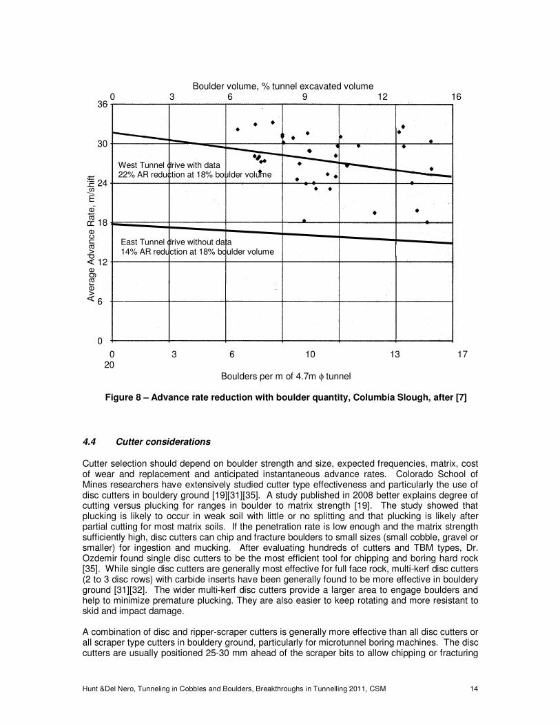
The effect of boulder quantities on advance rate using an open-face TBM was determined on the Columbia Slough project in Portland Oregon. Approximately 34,300 boulders were encountered within 2.5 km of 4.6m diameter open mode shield tunneling [7]. The average advance rate per shift decreased by 14 and 22 percent for the East and West drives, respectively, as boulder volume increased from 0 to 18 percent of the excavated volume – Figure 8. Data from another open-face shield [18] and a microtunnel project [42] indicated higher advance rate reductions ranging from 30 to 65 percent for boulder volumes ranging from 0.1 to 0.7 percent of excavated volume. The TBM penetration rate in bouldery ground depends on TBM type and power, cutter types and configuration, ground conditions and operation strategy. If the penetration rate is too high, cutters may be excessively damaged by dynamic impact forces and the cobbles and boulders will likely be ripped out off the soil matrix instead of cut. Studies and experience have shown that in order to achieve disc cutter rock chipping instead of boulder plucking, the penetration rate must be reduced down to a rate typical for rock TBMs (<10-12 mm/rev) [1][44]. The penetration rate used should balance the impacts of more frequent cutting tool replacement with an acceptable tunnel advance rate. On some recent projects (BWARI in Columbus and Brightwater West in Seattle) where earth pressure balance TBMs were used, the target and achieved advance rates were greater than practical for disc cutters to cut boulders [9][44]. The contractors on both projects elected to use rippers and scrappers instead of disc cutters. These cutters were successful at breaking boulders as discussed below.
Figure 7 - Commutation energy vs. particle
size, adopted from [35]
Hunt &Del Nero, Tunneling in Cobbles and Boulders, Breakthroughs in Tunnelling 2011, CSM 14
4.4 Cutter considerations
Cutter selection should depend on boulder strength and size, expected frequencies, matrix, cost of wear and replacement and anticipated instantaneous advance rates. Colorado School of Mines researchers have extensively studied cutter type effectiveness and particularly the use of disc cutters in bouldery ground [19][31][35]. A study published in 2008 better explains degree of cutting versus plucking for ranges in boulder to matrix strength [19]. The study showed that plucking is likely to occur in weak soil with little or no splitting and that plucking is likely after partial cutting for most matrix soils. If the penetration rate is low enough and the matrix strength sufficiently high, disc cutters can chip and fracture boulders to small sizes (small cobble, gravel or smaller) for ingestion and mucking. After evaluating hundreds of cutters and TBM types, Dr. Ozdemir found single disc cutters to be the most efficient tool for chipping and boring hard rock [35]. While single disc cutters are generally most effective for full face rock, multi-kerf disc cutters (2 to 3 disc rows) with carbide inserts have been generally found to be more effective in bouldery ground [31][32]. The wider multi-kerf disc cutters provide a larger area to engage boulders and help to minimize premature plucking. They are also easier to keep rotating and more resistant to skid and impact damage. A combination of disc and ripper-scraper cutters is generally more effective than all disc cutters or all scraper type cutters in bouldery ground, particularly for microtunnel boring machines. The disc cutters are usually positioned 25-30 mm ahead of the scraper bits to allow chipping or fracturing
0 3 6 10 13 17 20
Boulders per m of 4.7m φ tunnel
Figure 8 – Advance rate reduction with boulder quantity, Columbia Slough, after [7]
36
30
24
18
12
6
0
Avera
ge A
dvance R
ate
, m
/shift
Boulder volume, % tunnel excavated volume
0 3 6 9 12 16 18
West Tunnel drive with data 22% AR reduction at 18% boulder volume
East Tunnel drive without data 14% AR reduction at 18% boulder volume
Hunt &Del Nero, Tunneling in Cobbles and Boulders, Breakthroughs in Tunnelling 2011, CSM 15
of boulders before contact with the ripper-scrapers [1]. Evaluators have found that combination cutterheads are not only effective for optimal penetration rate, but significantly reduce the risk of catastrophic cutter damage and becoming obstructed [26][32][43]. BWARI and Brightwater West with Rippers
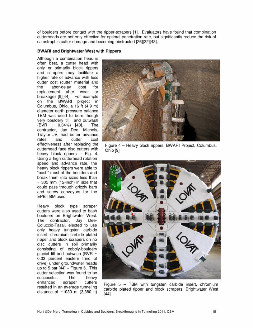
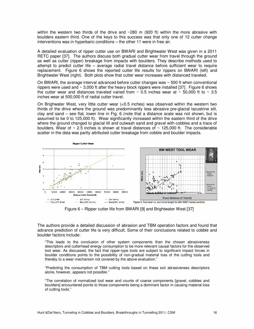
Although a combination head is often best, a cutter head with only or primarily block rippers and scrapers may facilitate a higher rate of advance with less cutter cost (cutter material and the labor-delay cost for replacement after wear or breakage) [9][44]. For example on the BWARI project in Columbus, Ohio, a 16 ft (4.9 m) diameter earth pressure balance TBM was used to bore though very bouldery till and outwash (BVR ~ 0.34%) [40]. The contractor, Jay Dee, Michels, Traylor JV, had better advance rates and cutter cost effectiveness after replacing the cutterhead face disc cutters with heavy block rippers – Fig. 4. Using a high cutterhead rotation speed and advance rate, the heavy block rippers were able to “bash” most of the boulders and break them into sizes less than ~ 305 mm (12-inch) in size that could pass through grizzly bars and screw conveyors for the EPB TBM used. Heavy block type scraper cutters were also used to bash boulders on Brightwater West. The contractor, Jay Dee-Coluccio-Tasai, elected to use only heavy tungsten carbide insert, chromium carbide plated ripper and block scrapers on no disc cutters in soil primarily consisting of cobbly-bouldery glacial till and outwash (BVR ~ 0.03 percent eastern third of drive) under groundwater heads up to 5 bar [44] – Figure 5. This cutter selection was found to be successful. The heavy enhanced scraper cutters resulted in an average tunneling distance of ~1030 m (3,380 ft)
Figure 4 – Heavy block rippers, BWARI Project, Columbus, Ohio [9]
Figure 5 – TBM with tungsten carbide insert, chromium carbide plated ripper and block scrapers, Brightwater West [44]
Hunt &Del Nero, Tunneling in Cobbles and Boulders, Breakthroughs in Tunnelling 2011, CSM 16
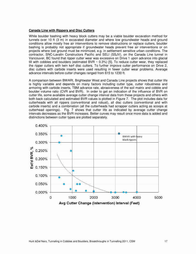
within the western two thirds of the drive and ~280 m (920 ft) within the more abrasive with boulders eastern third. One of the keys to this success was that only one of 12 cutter change interventions was in hyperbaric conditions – the other 11 were in free air. A detailed evaluation of ripper cutter use on BWARI and Brightwater West was given in a 2011 RETC paper [37]. The authors discuss both gradual cutter wear from travel through the ground as well as cutter (ripper) breakage from impacts with boulders. They describe methods used to attempt to predict cutter life – average radial travel distance before sufficient wear to require replacement. Figure 6 shows the reported cutter life results for rippers on BWARI (left) and Brightwater West (right). Both plots show that cutter wear increases with distanced traveled.
On BWARI, the average interval advanced before cutter changes was ~ 500 ft when conventional rippers were used and ~ 3,000 ft after the heavy block rippers were installed [37]. Figure 6 shows the cutter wear and distances traveled varied from ~ 0.5 inches wear at ~ 50,000 ft to ~ 3.5 inches wear at 500,000 ft of radial cutter travel.
On Brighwater West, very little cutter wear (<0.5 inches) was observed within the western two thirds of the drive where the ground was predominantly less abrasive pre-glacial lacustrine silt, clay and sand – see flat, lower line in Fig. 6 (note that a distance scale was not shown, but is assumed to be 0 to 125,000 ft). Wear significantly increased within the eastern third of the drive where the ground changed to glacial till and outwash sand and gravel with cobbles and a trace of boulders. Wear of ~ 2.5 inches is shown at travel distances of ~ 125,000 ft. The considerable scatter in the data was partly attributed cutter breakage from cobble and boulder impacts.
The authors provide a detailed discussion of abrasion and TBM operation factors and found that advance prediction of cutter life is very difficult. Some of their conclusions related to cobble and boulder factors include:
“This leads to the conclusion of other system components than the chosen abrasiveness descriptors and cutterhead energy consumption to be more relevant causal factors for the observed tool wear. As discussed, the fact that ripper-type tools are subject to significant impact forces in boulder conditions points to the possibility of non-gradual material loss of the cutting tools and thereby to a wear mechanism not covered by the above evaluation.” “Predicting the consumption of TBM cutting tools based on these soil abrasiveness descriptors alone, however, appears not possible.” “The correlation of normalized tool wear and counts of coarse components [gravel, cobbles and boulders] encountered points to those components being a dominant factor in causing material loss of cutting tools.”
Figure 6 – Ripper cutter life from BWARI [9] and Brightwater West [37]
Hunt &Del Nero, Tunneling in Cobbles and Boulders, Breakthroughs in Tunnelling 2011, CSM 17
Canada Line with Rippers and Disc Cutters
While boulder bashing with heavy block cutters may be a viable boulder excavation method for tunnels over 10 ft (3 m) in excavated diameter and where low groundwater heads and ground conditions allow mostly free air interventions to remove obstructions or replace cutters, boulder bashing is probably not appropriate if groundwater heads prevent free air interventions or on projects where lost ground must be minimized, e.g. in settlement sensitive urban conditions. The contractor, SNC-Lavalin Constructors Pacific and SELI (SSJV), on the Canada Line tunnel in Vancouver, BC found that ripper cutter wear was excessive on Drive 1 upon advance into glacial till with cobbles and boulders (estimated BVR ~ 0.3%) [5]. To reduce cutter wear, they replaced the ripper cutters with twin kerf disc cutters. To further improve cutter performance on Drive 2, disc cutters with carbide inserts were used resulting in fewer cutter wear problems. Average advance intervals before cutter changes ranged from 615 to 1230 ft. A comparison between BWARI, Brightwater West and Canada Line projects shows that cutter life is highly variable and depends on many factors including cutter type, cutter robustness and armoring with carbide inserts, TBM advance rate, abrasiveness of the soil matrix and cobble and boulder volume ratio (CVR and BVR). In order to get an indication of the influence of BVR on cutter life, some available average cutter change interval data from these projects and others with both back calculated and estimated BVR values is plotted in Figure 7. The plot includes data for cutterheads with all rippers (conventional and robust), all disc cutters (conventional and with carbide inserts) and a combination (all the cutterheads had scrapper cutters acting as scoops at cutterhead openings). Fig. 7 shows that cutter life as indicated by average cutter change intervals decreases as the BVR increases. Better curves may result once more data is added and distinctions between cutter types are plotted separately.
Hunt &Del Nero, Tunneling in Cobbles and Boulders, Breakthroughs in Tunnelling 2011, CSM 18
Microtunneling
When microtunneling, a combination cutterhead with scrapper and disc cutters is essential to minimize risk of getting stuck from severe cutter wear [26]. When the anticipated maximum boulder sizes are greater than approximately 50 percent of the MTBM diameter, conditions rapidly approach those encountered during rock microtunneling. A single boulder greater than 50% of the excavated diameter can cause a stuck MTBM unless it is equipped with cutters and power suitable for rock. A 2009 overview of rock microtunneling experience provided many useful guidelines that are applicable to microtunneling in cobbles and boulders [29]. A recently completed project in Milwaukee successfully used two adequately powered MTBMs with combination heads (scraper and disc cutters) to bore through cobbly-bouldery glacial till and outwash (BVR ~ 0.1 to 10%) and a dolomite rock ridge over 400 feet wide [20]. Drives lengths of 405 and 800 feet were achieved without cutter changes and severe damage in the extremely difficult bouldery till, mixed-face and full face rock conditions encountered. In summary, many factors should be considered when selecting cutters for cobbly-bouldery ground. Heavy, block type scraper cutters protected with carbide inserts may be the most cost effective where face access is available and a stable face in free air is expected. A combination head of ripper-scraper and disc cutters may be most cost effective for microtunneling and for pressurized face tunneling particularly where hyperbaric interventions may be required to change cutters.
4.5 Problematic Ground
While robust MTBMs with combination heads, particularly if face access is also provided, significantly increase the chances of good advance rates and avoidance of stuck drives, some combinations of cobbles, boulders and soil matrix type remain very risky. Probably the most treacherous condition for MTBM or pressurized face TBM tunneling is a combination of cobbles and boulders with a BVR greater than 5 percent in open, high permeability gravel or sand-gravel matrix with fines less than 3 percent. Bentonite slurry at the face may flow excessively into the gravel and may not have sufficient viscosity to form a filter cake and prevent excess flowing ground. With earth pressure balance tunneling, such ground is very difficult to properly condition and may result in inadequate face pressure and excess flow through the screws. If cutterhead openings are excessive, the excavation chamber may quickly become filled with gravel, cobbles and boulders that resist crushing and flow through the intake ports or screw conveyor resulting in a blocked chamber and a stalled MTBM or TBM. Significant reductions in the cutterhead opening ratio to less than 20 percent may be required to obtain face stability and reduce risk of stalling an adequately powered MTBM in these conditions [23]. Another high risk is that very abrasive ground and cobble and boulder impact damage may result in excessive cutter-cutterhead-crusher-intake port wear severely reducing the average advance rate or resulting in a stuck MTBM and possibly inability to complete the project with the selected MTBM [3][38]. When cobble and boulder volume ratios exceed approximately 10 percent and very abrasive matrix soils are present, microtunneling should be avoided or special measures and pay items provided to manage the likely advance rate and abrasion challenges.
5 SUMMARY AND CONCLUSIONS
During the past twenty years, the tunneling industry has made considerable improvements in capability to successfully microtunnel and tunneling in cobbly-bouldery ground. Subsurface investigations have gotten more varied and focused to obtain necessary data. A database of typical boulder volume ratios for glacial and alluvial soil types has grown. Designers have developed practical and statistical methods to predict boulder occurrences. These methods have been used with reasonable success on well over 50 projects and perhaps in the hundreds. Baselining and pay items (where applicable) have helped to significantly reduce the risk of excavating through cobbly-bouldery ground. Risk management methods should be used to
Hunt &Del Nero, Tunneling in Cobbles and Boulders, Breakthroughs in Tunnelling 2011, CSM 19
assess cobble and boulder risks along all portions of the alignment. Where the consequences of getting stuck are high or where the cost of interventions to change cutters is excessive, contract documents might require more robust MTBMs (or TBMs) with face access and combination roller and scraper cutters. Where conditions are bad and risks are high, redundancy and backup plans should be designed with appropriate pay items to manage uncertainties and risks. Many useful papers on subsurface investigation, baselining, tunneling method selection and case histories have been published, particularly within the past 20 years. A bibliography of papers on tunneling in cobbly and bouldery ground follows the cited references.
6 REFERENCES
[1] Babendererde, L., Problems of TBMs in Water Bearing Ground, In: Proceedings of
Summerschool 2003 on Rational Tunnelling, University of Innsbruck, (2003) 20p.
[2] Boone S.J., Westland J., Busbridge J.R., & Garrod B., Prediction of Boulder Obstructions, In: Tunnels & Metropolises, Proceedings of World Tunnelling Congress 1998, ITA-AETES, (1998) 817-822.
[3] Camp C., Microtunneling and HDD through Alluvium in Chula Vista, CA, Proceedings of North American No-Dig 2003, NASTT, paper F-3-01, (2007.103) 10p.
[4] Castro R., Webb R., & Nonnweiler J., Tunneling Through Cobbles in Sacramento, California. In: Proceedings 2001 Rapid Excavation and Tunneling Conference, W.H. Hansmire & I.M. Gowring, (Eds). SME, Littleton, Colorado, (2001-74) 907-918.
[5] Ciamei A. & Moccichino M., EPB TBM Under the City Centre of Vancouver: Risk Management and Settlement Control, "Safe Tunnelling for the City and for the Environment,” Proceedings of World Tunnelling Congress, Budapest, ITA-AITES, 2009, 17p.
[6] Cowles B., Guardia R.J., Robinson R.A., Andrews R. & Molvik D., Predicted versus Actual Obstructions for Two Pipe-Jacked Tunnels of the Henderson CSO, Seattle, Washington, In: Proceedings 2005 Rapid Excavation and Tunneling Conference, SME, (2005-101) 1253-1261.
[7] Cronin H.E. & Coluccio J.J., The True Cost of Boulders in a Soft Ground Tunnel. In: Proceedings 2003 Rapid Excavation and Tunneling Conference, R.A. Robinson, & J.M. Marquardt, (Eds), SME, Littleton, Colorado (2003-48) 535-539.
[8] DiPonio D.D., Manning F.B & Alberts J.B., An Encounter with Boulders During Soft Ground Tunneling in Wayne County, Michigan: A Case History. In: Proceedings of 2003 Rapid Excavation and Tunneling Conference. R.A. Robinson, & J.M. Marquardt, (Eds), Littleton, Colorado: SME (2003-47) 522-534.
[9] DiPonio M.A., Chapman D. & Bournes C., EPB Tunnel Boring Machine Design for Boulder Conditions, In: Proceedings of 2007 Rapid Excavation and Tunneling Conference, Traylor M.T. & Townsend J.W. (Eds), SME, Littleton, Colorado, (2007) 215-228.
[10] Ditlevsen O., Probability of boulders. In: Storebaelt East Tunnel, N.J. Gimsing, (Ed). A/S Storebæltsforbindelsen, Copenhagen, (1997) 39–41.
[11] Ditlevsen O., A story about distributions of dimensions and locations of boulders, Probabilistic Engineering Mechanics, Elsevier-Science Direct, (21- 1) (2006) 9-17.
[12] Donovan J.G., Fracture Toughness Based Models for the Prediction of Power Consumption, Product Size, and Capacity of Jaw Crushers, PhD Thesis in Mining and Minerals Engineering, Virginia Polytechnic Institute, 2003, 93-106.
Hunt &Del Nero, Tunneling in Cobbles and Boulders, Breakthroughs in Tunnelling 2011, CSM 20
[13] Dowden P.B., & Robinson R.A., Coping with Boulders in Soft Ground Tunneling. In Hansmire, W.H. & Gowring, I.M. (eds). Proceedings 2001 Rapid Excavation and Tunneling Conference, SME, Littleton, Colorado, (2001-78) 961-977.
[14] Essex R.J., Subsurface Exploration Considerations for Microtunneling/Pipe Jacking Projects, Proceedings of Trenchless Technology: An Advanced Technical Seminar, Trenchless Technology Center, Louisiana Tech University, Ruston, LA., (1993) 276-287.
[15] Felletti F. & Pietro-Beretta G., Expectation of boulder frequency when tunneling in glacial till: A statistical approach based on transition probability, Elsevier-Science Direct, Engineering Geology, (108) (2009) 43-53.
[16] Frank G. & Chapman D., Geotechnical Investigations for Tunneling in Glacial Soils, In: Proceedings of 2001 Rapid Excavation and Tunneling Conference, Hansmire W.H. & Gowring I.M. (Eds), SME, Littleton, Colorado, (2001-26) 309-324.
[17] Frank G. & Chapman D., New Model for Characterizing the Cobble and Boulder Fraction for Soft Ground Tunneling, Hutton J.D. & Rogstad D. (Eds), In: Proceedings 2005 Rapid Excavation and Tunneling Conference, SME, (2005-60) 780-791.
[18] Gilbert M.B. & Dentz E.S., L-73 Tunnel, Woodbury, Minnesota, Proceedings North American Tunneling 2008, SME (2008.83) 670-676
[19] Goss C.M., Predicting Boulder Cutting in Soft Ground Tunneling, In: Proceedings of North American Tunneling 2002, L. Ozdemir, (Ed), Rotterdam: Balkema, (2002-4) 37-46 .
[20] Grolewski B., Hunt S.W., Hottinger G.A., Martin R. & Ellis L., Microtunneling Experience On The Barclay/4th/Chase MIS Replacement Project, In: Proceedings of North American No-Dig 2010, NASTT, Paper F-5-01.
[21] Gould J.P., Geotechnology in Dispute Resolution, Journal of Geotechnical Engineering. ASCE. New York. Vol. 121, (1995-7) 523-534.
[22] Heuer R.E., Site Characterization for Underground Design and Construction, Site Characterization & Exploration. ASCE. New York, (1978) 39-55.
[23] Hickey M. & Staheli K., Woods Trunk Sewer Replacement Project – A Challenge, Proceedings of North American No-Dig 2007, NASTT Paper C-1-03, (2007.39) 10p.
[24] Hunt S.W. & Angulo M., Identifying and Baselining Boulders for Underground Construction. In: Fernandez G. & Bauer R.A. (Eds), Geo-Engineering for Underground Facilities, ASCE, Reston Virginia, 1999, 255-270.
[25] Hunt S.W., Compensation for Boulder Obstructions. L. Ozdemir (ED), In: Proceedings of The North American Tunneling 2002, Ozdemer L., (Ed), Rotterdam: Balkema, (2002-3) 23-36.
[26] Hunt S.W. & Mazhar F.M., MTBM and Small TBM Experience with Boulders, Ozdemir L. (ED), In: Proceedings of North American Tunneling 2004, Ozdemir L. (Ed.), SME, Littleton, Co., (2004-6) 47–64.
[27] Hunt S.W., Risk Management For Microtunneled Sewers, Proceedings of Collection Systems 2004: Innovative Approaches to Collection Systems Management, Water and Environment Federation, Alexandria, VA, Paper 9D (2004) 15p
[28] Hunt, S.W., Lewtas, T., Weltin, W.R. & Grolewski, B., 2006-38, Pipe Jacking On The Marquette Interchange Storm Sewers Project, Proceedings of North American No-Dig 2006, NASTT, C-2-02
Hunt &Del Nero, Tunneling in Cobbles and Boulders, Breakthroughs in Tunnelling 2011, CSM 21
[29] Hunt S.W. & Del Nero, D.E, Rock Microtunneling – An Industry Review, Proceedings of International No-Dig 2009, NASTT/ISTT, Paper B-2-01, (2009) 11p
[30] Hunt S.W. & Del Nero, D.E, Two Decades of Advances Investigating, Baselining and Tunneling in Bouldery Ground, Proceedings of World Tunnelling Congress, Vancouver, ITA-TAC, 2010, 8p.
[31] Kieffer D.S., Leelasukseree C., & Mustoe G.G.W., Disc Cutter Performance in Boulder-Laden Ground, In: Proceedings of North American Tunneling 2008, SME, Littleton, Colorado, (2008) 129-136.
[32] Krauter D., When Boulders Attack – Roller Cutters in Soft Ground, Tunnel Business Magazine, (2008-2) 22-23.
[33] Legget R.F., Geology and Geotechnical Engineering, Journal of the Geotechnical Engineering Division. ASCE. New York. Vol. 105, No. GT3. (1979-3) 342-391.
[34] Neyer J.C., Geotechnical Investigation for Tunnels in Glacial Soils. Mann C.D. & Kelley M.N. (Eds), In: Proceedings of 1985 Rapid Excavation and Tunneling Conference. SME. Littleton CO., (1985-1) 3-15.
[35] Ozdemir L., Comparison of Cutting Efficiencies of Single-Disc, Multi-Disc, and Carbide Cutters for Microtunneling Applications, No-Dig Engineering, Trenchless Technology, Vol. 2, No. 1 (1995-3) 18-23.
[36] Poot S., Boone S.J. Westland J., & Pennington B., Predicted Boulder Frequency Compared to Field Observations During Construction of Toronto’s Sheppard Subway, In: Proceedings of Tunneling Association of Canada 2000 Conference. TAC, (2000) 47-54.
[37] Shinouda MM, Gwildis UG, Wang P & Hodder W. 2011. Cutterhead Maintenance for EPB Tunnel Boring Machines. Proceedings, 2011 Rapid Excavation and Tunneling Conference. Redmond S. & Romero V. (eds). SME. R2011.80. 1068-1082.
[38] Staheli K., Bennett D., Maggi M.A, Watson M.B. &. B.J. Corwin, Folsom East 2 Construction Proving Project: Field Evaluation of Alternative Methods in Cobbles and Boulders. In: Geo-Engineering for Underground Facilities, Fernandez G., & Bauer R. (Eds), ASCE, Reston, Virginia, (1999) 720-730
[39] Stoll U.W., Probability That A Soil Boring Will Encounter Boulders, In: Conference on Better Contracting for Underground Construction, Michigan Section of ASCE, Detroit (1976) 34-48.
[40] Theys J.P., Shinouda M.M., Gilbert G.W. & Frank G.D., Construction of the Big Walnut Augmentation/Rickenbacker Interceptor Tunnel (BWARI, Part 1) — Columbus, Ohio, In: Proceedings of 2007 Rapid Excavation and Tunneling Conference, SME, (2007.60) 712-740.
[41] Tang W., Quek S.T., Statistical model of boulder size and fraction. Journal of Geotechnical and Geoenvironmental Engineering, 112 (1), ASCE (1986) 79–90.
[42] Tarkoy P.J., Challenges & Successes in Micro-Tunneling on the Chelsea River Crossing. Proceedings of 5th International Microtunneling Symposium – BAUMA 2001. (2001) 16p
[43] Tarkoy P.J., The boulder facts of life, World Tunnelling, (2008-12) 25-28.
[44] Trisi W., Frank G. & DiPonio M., Brightwater Conveyance Tunnel, West Contract (BT-4), King County, Seattle, Washington, USA;TBM System Design to Facilitate Cuttinghead Maintenance in Adverse Conditions; G., Proceedings of World Tunnelling Congress, Vancouver, ITA-TAC, W2010-47, 8p.
Hunt &Del Nero, Tunneling in Cobbles and Boulders, Breakthroughs in Tunnelling 2011, CSM 22
[45] USBR, Engineering Geology Field Manual, 2nd Ed., http://www.usbr.gov/pmts/geology/geoman.html (2001)
[46] G. Young, Personal communication, Underground Imaging Technologies, Inc, (2009-12)
7 BIBLIOGRAPHY
Papers shown in bold type are considered by the authors to be better references and higher priority for suggested reading on tunneling in cobbly-bouldery ground.
7.1 References on subsurface investigation and boulder baselining
Alsup S., 1974, Recommended Borehole Investigation for Soft Ground, Subsurface Exploration for Underground Excavation and Heavy Construction. American Society of Civil Engineers, New York, pp117-127.
Boone, S.J., Westland, J., Busbridge, J.R. & Garrod, B., 1998, Prediction of Boulder Obstructions, Tunnels & Metropolises, Proceedings of 1998 World Tunnelling Congress, W1998.126. 817-822.
Boone, S.J., Poschmann, A., Pace, A. & Pound, C., 2001. Characterization of San Diego’s Stadium Conglomerate for Tunnel Design, Proceedings 2001 Rapid Excavation and Tunneling Conference, Hansmire, W.H. & Gowring, I.M. (eds). SME, R2001.4. 33-46.
Brierley G.S., Howard, A.L. and Romley R.E. 1991. Subsurface Exploration Utilizing Large Diameter Borings for the Price Road Drain Tunnel. Proceedings, 1991 Rapid Excavation and Tunneling Conference. Society for Mining Metallurgy and Exploration. Littleton CO. R1991.5. 61-78.
Brierley, G.S. (1996). “Microtunneling! Schmicrotunneling!” Trenchless Technology. September 1996, p8.
Cowles, B., Guardia, R.J., Robinson, R.A., R. Andrews & Molvik, D., 2005-101, Predicted versus Actual Obstructions for Two Pipe-Jacked Tunnels of the Henderson CSO, Seattle, Washington, Proceedings 2005 Rapid Excavation and Tunneling Conference, SME,1253-1261.
Davis R. and Oothoudt T., 1997, The Use of Rotosonic Drilling in Environmental Investigations, Soil and Groundwater Cleanup, May 1997, pp34-36.
De Pasquale, G. and Pinelli G., 1998, No-Dig Application Planning Using Dedicated Radar Techniques. No-Dig International, Mining Journal LTD, London, February 1998, pp I-12 to I-14.
Ditlevsen, O, 2006, A story about distributions of dimensions and locations of boulders, Probabilistic Engineering Mechanics, Volume 21, Issue 1, January 2006, Pages 9-17
Ditlevsen O., 1997, Probability of boulders. In: Gimsing NJ, editor. East Tunnel, Copenhagen, 1997. p. 39–41 (A/S Storebæltsforbindelsen).
Essex, R.J., 1993, Subsurface Exploration Considerations for Microtunneling/Pipe Jacking Projects. Proceedings of Trenchless Technology: An Advanced Technical Seminar. Trenchless Technology Center, Louisiana Tech University, Ruston, LA. pp276-287.
Essex, R.J. & Klein, S.J. 2000-9. Recent developments in the use of Geotechnical Baseline Reports. In Ozdemer, L. (ed). Proceedings of North American Tunneling 2000, Rotterdam: Balkema, pp79-84.
Hunt &Del Nero, Tunneling in Cobbles and Boulders, Breakthroughs in Tunnelling 2011, CSM 23
Felletti, F., & Pietro-Beretta, G., 2009, Expectation of boulder frequency when tunneling in glacial till: A statistical approach based on transition probability, Engineering Geology, Volume 108, Issues 1-2, 14 September 2009, Pages 43-53.
Frank, G., Daniels, J. & Guy, ED. 2000.3. The Use of Borehole Ground Penetrating Radar in Determining the Risk Associated with Boulder Occurrence, Proceedings of North American No-Dig 2000, NASTT, p 37.
Frank, G. & Daniels, J. 2000-46. The Use of Borehole Ground Penetrating Radar in Determining the Risk Associated With Boulder Occurrence. In Ozdemer, L. (ed). Proceedings Of The North American Tunneling 2000, Rotterdam: Balkema. pp427-436
Frank, G. & Chapman, D. 2001-26. “Geotechnical Investigations for Tunneling in Glacial Soils,” In Hansmire, W.H. & Gowring, I.M. (eds). Proceedings 2001 Rapid Excavation and Tunneling Conference, Littleton, Colorado: SME. pp309-324.
Frank, G. & Chapman, D. 2005-60. New Model for Characterizing the Cobble and Boulder Fraction for Soft Ground Tunneling, Proceedings 2005 Rapid Excavation and Tunneling Conference, SME, pp780-791.
Gould, J.P. 1995. Geotechnology in Dispute Resolution. Journal of Geotechnical Engineering. ASCE. New York. Vol. 121, No. 7. July 1995, pp523-534. [also see discussion in ASCE Journal of Geotechnical and Geoenvironmental Engineering, June 1997, pp592-599]
Heuer, R.E., 1978. Site Characterization for Underground Design and Construction. Site Characterization & Exploration. ASCE. New York, pp39-55.
Hindle, D.J., 1995. Geotechnical Appraisal. World Tunneling. London. Nov. 1995, pp371-373.
Hunt, S.W. and Fradkin, S.B., 1991, Costly Environmental and Geotechnical DSC Claims Resulting from Exploration Program and Reporting Inadequacies. Proceedings, 34th Annual Meeting of Association of Engineering Geologists. Association of Engineering Geologists, Greensburg, PA, pp127-136.
Hunt, S.W. & Angulo. M., 1999. Identifying and Baselining Boulders for Underground Construction. In Fernandez, G. & Bauer (eds), Geo-Engineering for Underground Facilities, Reston, Virginia: ASCE, pp255-270
Hunt, S.W., 2004, Risk Management for Microtunneled Sewers, In Proceedings of Collection Systems 2004: Innovative Approaches to Collection Systems Management, Milwaukee, Wisconsin, Water Environment Federation, Inc., Alexandria, VA., Session 9, Paper 4, 15p.
Hunt S.W. & Del Nero, D.E, Two Decades of Advances Investigating, Baselining and Tunneling in Bouldery Ground, Proceedings of World Tunnelling Congress, Vancouver, ITA-TAC, 2010, 8p
Legget R.F., 1979, Geology and Geotechnical Engineering. Journal of the Geotechnical Engineering Division. ASCE. New York. Vol. 105, No. GT3. March 1979, 342-391.
Medley, E.W., 2002, Estimating Block Size Distributions of Melanges and Similar Block-in-Matrix Rocks (Bimrocks), Proceedings of 5th North American Rock Mechanics Symposium (NARMS), ed. by Hammah, R., Bawden, W., Curran, J. and Telesnicki, M. ; July 2002, Toronto, Canada; University of Toronto Press, pp. 509-606
Miller R.J. (1996). “Hazard Recognition in Trenchless Technology.” No-Dig Engineering. Vol.3. No. 6. November/December 1996, 13-15.
Neyer, J.C., 1985-1. Geotechnical Investigation for Tunnels in Glacial Soils. Proceedings of 1985 Rapid Excavation and Tunneling Conference. Society for Mining Metallurgy and Exploration. Littleton CO., pp3-15.
Osterberg, J.O., 1978, Failures in Exploration Programs, Site Characterization & Exploration. ASCE. New York, pp3-9.
Hunt &Del Nero, Tunneling in Cobbles and Boulders, Breakthroughs in Tunnelling 2011, CSM 24
Osterberg, J.O. (1989). ”Necessary Redundancy in Geotechnical Engineering.” Journal of Geotechnical Engineering. ASCE. New York. Vol. 115, No. 11. November 1989, 1513-1531.
Ovesen, N.K., 1997. Invited lecture: geotechnical aspects of the Storebaelt Project, Proceedings of the 14th Int. Conf. on Soil Mechanics and Foundation Engineering. Hamburg 6–12 Sept. Eds. Publ. Committee. Balkema, Rotterdam, pp. 2097–2114.
Poot, S., Boone, S.J., Westland, J. & Pennington, B, 2000, Predicted Boulder Frequency Compared to Field Observations During Construction of Toronto’s Sheppard Subway, Proceedings of Tunneling Association of Canada 2000 Conference. TAC, pp 47-54.
Schmidt, B., 1974, Exploration for Soft Ground Tunnels - A New Approach, Subsurface Exploration for Underground Excavation and Heavy Construction. American Society of Civil Engineers, New York, pp84-96.
Smirnoff T.P. and Lundin T.K., 1985-26, Design of Initial and Final Support of Pressure Tunnels in the Phoenix "SGC". Proceedings, 1985 Rapid Excavation and Tunneling Conference, Society for Mining Metallurgy and Exploration. Littleton CO. pp 428-438.
Staheli K. & Maday L., 2009. Geotechnical Baseline Reports-Applying the Guidelines to Microtunneling, International No-Dig 2009, A-2-04, 2009-9, 8p.
Parnass J. & and Staheli S. 2010. The Legal Impact of Geotechnical Baselines. Proceedings of North American No-Dig 2010. NASTT. ND2010.88. D-5-03
Parnass J, Staheli S, Hunt S, Hutchinson M, Fowler J & Maday L. 2011. A Discussion on Geotechnical Baseline Reports and Legal Issues, Proceedings of North American No-Dig 2010. NASTT. ND2011.51, C-2
Stoll, U.W., 1976. Probability That A Soil Boring Will Encounter Boulders, Conference on Better Contracting for Underground Construction. Michigan Section of American Society of Civil Engineers. Detroit. pp34-48.
Tang, W. and Quek S.T. 1986. “Statistical Model of Boulder Size and Fraction.” Journal of Geotechnical Engineering. ASCE. New York. Vol. 112, No. 1. January 1986, 79-90.
Tarkoy, P.J., 1992, The Achilles Heel of Trenchless Technology: An Editorial Comment. Trenchless Technology. September/October 1992, pp25, 41.
Tarkoy, P.J., 1999, Microtunneling in Spite of Inherent Risks, TBM: Tunnel Business Magazine, December 1999, pp23-24.
Tarkoy, P.J., 2008, The boulder facts of life, World Tunnelling, December 2008, pp25-28.
Technical Committee on Geotechnical Reports of the Underground Technology Research Center. 1997. Geotechnical Baseline Reports for Underground Construction. Randall J. Essex, Editor. ASCE. New York
U.S. National Committee on Tunneling Technology. 1984. Geotechnical Site Investigations for Underground Projects. National Academy Press. Washington D.C. Vol. 1.
Ward, D.C., Robinson, R.A. & Hopkins, TW. 2002. Managing Uncertainty and Risk - The Exploration Program for Seattle's Proposed Light Rail Tunnels, Proceedings North American Tunneling 2002, Rotterdam: Balkema, N2002.26. p219-
7.2 References on tunnel excavation methods, cutters in bouldery ground
ATS. 2006. Current & Emerging Rock Cutting Technology, Australian Tunnelling Society, http://www.ats.org.au/index.php?option=com_docman.
Hunt &Del Nero, Tunneling in Cobbles and Boulders, Breakthroughs in Tunnelling 2011, CSM 25
Babendererde L. 2003. Problems of TBMs in Water Bearing Ground, Proceedings of Summerschool 2003 on Rational Tunnelling, University of Innsbruck, 20p.
Becker C. 1995. The Choice Between EPB- and Slurry Shields: Selection Criteria by Practical Examples. In Williamson, G.E. & Fowring I.M. (eds). Proceedings of 1995 Rapid Excavation and Tunneling Conference, Littleton CO: SME, R1995-31. 479-492.
Burger W. 2007. Design Principles for Soft Ground Cutterheads, Proceedings of 2007 Rapid Excavation and Tunneling Conference, SME, 2007.64. p784
Cording EJ, Brierley GS, Mahar JW, & Boscardin M.D. 1989. Controlling Ground Movements During Tunneling.” The Art and Science of Geotechnical Engineering. Editors: Cording, E.J., Hall W.J., Haltiwanger J.D., Hendron, A.J. Jr., and Mesri G. Prentice Hall. New Jersey, pp478-482.
Castro R, Webb R. & Nonnweiler J. 2001. Tunneling Through Cobbles in Sacramento, California. In Hansmire, W.H. & Gowring, I.M. (eds). Proceedings 2001 Rapid Excavation and Tunneling Conference:. Littleton, Colorado: SME., R2001-74. pp907-918
DiPonio M.A, Chapman D., & Bournes C. 2007. EPB Tunnel Boring Machine Design for Boulder Conditions, Proceedings of 2007 Rapid Excavation and Tunneling Conference, SME, 2007-20. 215-228.
Dowden PB & Robinson RA. 2001. Coping with Boulders in Soft Ground Tunneling. In Hansmire, W.H. & Gowring, I.M. (eds). Proceedings 2001 Rapid Excavation and Tunneling Conference, Littleton, Colorado: SME. 2001-78. 961-977.
Friant JE & Ozdemir L. 1994. Development of the High Thrust Mini-Disc Cutter for Microtunneling Applications. No-Dig Engineering. June 1994: pp12-15.
Fuerst T. 2008, Successful Technology for Utility Installation In Unstable Geology (60-96 Inches Diameter) [SBU], 2008 Underground Construction Technology International Conference & Exhibition, Track 8B, U2008.47, 9p.
Goss CM. 2002. “Predicting Boulder Cutting in Soft Ground Tunneling,” In Ozdemer, L. (ed), Proceedings of North American Tunneling 2002, Rotterdam: Balkema. N2002-4. p37-46.
Grolewski B, Hunt SW, Hottinger GA, Martin R & Ellis L. 2010. Microtunneling Experience On The Barclay/4th/Chase MIS Replacement Project, In: Proceedings of North American No-Dig 2010, NASTT, ND2010.132 .Paper F-5-01
Hunt SW & Mazhar FM. 2004, MTBM and Small TBM Experience with Boulders, Proceedings of North American Tunneling 2004, Ozdemir (ed.), N2004-6. pp 47–64.
Jee W.W. & Ha S-G. 2007. Feasible Boulder treatment methods for soft ground shielded TBM; Proceedings of World Tunneling Congress 2007. Taylor & Francis Group, London. W2007.35. p217-222.
Kieffer DS, Leelasukseree C, & Mustoe GGW. 2008., Disc Cutter Performance in Boulder-Laden Ground, Proceedings of North American Tunneling 2008, SME, N2008-17. 129-136.
Kieffer DS, Leelasukseree C, & Mustoe GGW. 2008, Discs and Boulders, Tunnels and Tunnelling International, Nov, 2008, pp 43-46.
Klein SJ, Nagle GS, Raines GL,1996, Important Geotechnical Considerations in Microtunneling. No-Dig Engineering. Vol. 3. No. 4. July/August (1996), pp9-12.
Kneib G, Kassel A & Lorenz K. 2000. Automatic Seismic Prediction ahead of the Tunnelling Machine. European Association of Geoscientists and Engineers (EAGE) Conference, Helsinki.
Krauter D. 2008. When Boulders Attack – Roller Cutters in Soft Ground, Tunnel Business Magazine, February 2008. 22-23.
Neil D. K. Haramy, J Descour & D. Hanson. 1999. Imaging Ground Conditions ahead of the Face. World Tunnelling, November, 425–429.
Hunt &Del Nero, Tunneling in Cobbles and Boulders, Breakthroughs in Tunnelling 2011, CSM 26
Nishitake S. 1987. Earth Pressure Balanced Shield Machine to Cope with Boulders. In Jacobs, J.M. & Hendricks R.S. (eds). Proceedings, 1987 Rapid Excavation and Tunneling Conference. Littleton CO: SME, R1987.35. 552-572
Shinouda MM, Gwildis UG, Wang P & Hodder W. 2011. Cutterhead Maintenance for EPB Tunnel Boring Machines. Proceedings, 2011 Rapid Excavation and Tunneling Conference. Redmond S. & Romero V. (eds). SME. R2011.80. 1068-1082.
Staheli K & Hermanson, G. 1997. What to Do When your Head Gets Stuck, Proceedings of Proceedings of North American No-Dig 1997, NASTT, pp436-446.
Staheli K, Bennett D, Maggi MA, Watson MB & Corwin BJ. 1999. Folsom East 2 Construction Proving Project: Field Evaluation of Alternative Methods in Cobbles and Boulders. In Fernandez, G. & Bauer (eds). Geo-Engineering for Underground Facilities, Reston, Virginia: ASCE. 720-730.
Ozdemir L. 1995. Comparison of Cutting Efficiencies of Single-Disc, Multi-Disc an Carbide Cutters for Microtunneling Applications. No-Dig Engineering. March 1995. pp18-23.
Wallis S. 2000. Elbe Tunnel: Cutting Edge Technology, Tunnels & Tunnelling International, January 2000, V32 N1, pp.24-27.
7.3 References on compensation for boulder encounters or obstructions
Cronin HE & Coluccio JJ. 2003. The True Cost of Boulders in a Soft Ground Tunnel. 2003. In Robinson, R.A. & Marquardt, J.M. (eds), Proceedings 2003 Rapid Excavation and Tunneling Conference. Littleton, Colorado: SME. R2003-48. 535-539.
Hunt SW. 2002. Compensation for Boulder Obstructions. In Ozdemer, L. (ed), Proceedings Of The North American Tunneling 2002, Rotterdam: Balkema, N2002-3. 23-36.
Mason DJ III, Berry RSJ &. Hatem DJ. 1999. Removal of Subsurface Obstructions: An Alternative Contractual Approach. In Fernandez, G. & Bauer (eds). Geo-Engineering for Underground Facilities: Reston, Virginia: ASCE. pp1164-1175.
Samuels R. 2000. Use of contract unit prices for fair and reasonable payment of changes in baseline quantities for tunnel construction, Proceedings of The North American Tunneling 2000, Ozdemir (ed.). Balkema, N2000.32, p299-303.
Jee W.W. & Ha S-G. 2007. Feasible Boulder treatment methods for soft ground shielded TBM; Underground Space – the 4th Dimension of Metropolises, Proceedings of 2007 World Tunnelling Congress, Barták, Hrdina, Romancov & Zlámal (eds). Taylor & Francis Group, London. W2007.35. 217-222.
7.4 Case histories with references to boulder encounters
Abramson L., Cochran J., Handewith H & MacBriar T. 2002-25, Predicted and actual risks in construction of the Mercer Street Tunnel. In Ozdemer, L. (ed). Proceedings Of The North American Tunneling 2002, Rotterdam: Balkema. N2002-25. 211-218.
Anheuser L. 1995. Specific Problems of Very Large Tunneling Shields, Proceedings 1995 Rapid Excavation and Tunneling Conference. Littleton, Colorado: SME, R1995.30. 467-477.
Atalah A. 2008. A Case Study of the Permars Run Relief Sewer Alignment in Steubenville, Ohio, Proceedings of North American No-Dig 2008, NASTT, ND2008.35. B-4-03.
Becker C. 1989. Tunnelling in Glacial Deposits at the Example Grauholztunnel Bern (Makro-Tunnelling) and Sewer Moosstrasse Salzburg (Makro- Tunnelling), Proceedings, 1989 Rapid Excavation and Tunneling Conference, Society for Mining Metallurgy and Exploration, Littleton, CO., R1989.43. 701-714
Hunt &Del Nero, Tunneling in Cobbles and Boulders, Breakthroughs in Tunnelling 2011, CSM 27
Beieler R, Gonzales D & Molvik D. 2003. City of Seattle - Tolt Pipeline No. 2 Bear Creek and Snoqualimie River Microtunnels. Proceedings of North American No-Dig 2003, NASTT, ND2003.7. A-2-03.
Bennett D & Wallin MS. 2003. American River Crossings: Then and Now. Proceedings of North American No-Dig 2003, NASTT, ND2003-55. D-2-02.
Boone SJ, McGaghran S, Bouwer G. & Leinala T. 2002. Monitoring the performance of earth pressure balance tunneling in Toronto, Proceedings North American Tunneling 2002, Rotterdam: Balkema, N2002.35. p293
Boscardin M., Wooten, R.L. & Taylor J.M. 1997. Pipe Jacking to Avoid Contaminated Groundwater Conditions. In Proceedings of Trenchless Pipeline Projects – Practical Applications, Boston, MA. June 8-11, 1997. ASCE Pipeline Division, pp135-141
Budd TH & Cooney AM. 1991. Milwaukee's North Shore 9 Collector System - A Case History. In Wightman, W.D. & McCarry D.C. (eds). Proceedings 1991 Rapid Excavation and Tunneling Conference. SME, R1991.20. 349-378
Budd T & Goubanov V. 2003. East Central Interceptor Sewer, Los Angeles, California, Proceedings 2003 Rapid Excavation and Tunneling Conference. SME. R2003.98. 1143-
Cai Z, Solana AG, O’Conner N & Lloyd P. 2009. Microtunneling a RCP Sewer with Crossings, International No-Dig 2009, NASTT-ISTT, ND2009-30. B-2-02, 11p.
Cai Z, Solana, AG, O’Connor N & Lloyd P. 2009. Microtunneling 1.2-Mile, 72-in RCP with Crossings of NJ Turnpike and CSX Railroads. Proceedings 2009 Rapid Excavation and Tunneling Conference. SME. R2009.44. 558-569.
Camp C. 2007. Microtunneling and HDD through Alluvium in Chula Vista, CA, Proceedings of North American No-Dig 2003, NASTT. ND2007.103. F-3-01, 10p.
Casey EF & Ruggiero. 1981. The Red Hook Intercepting Sewer – A Compressed Air Tunnel Case History. In Wightman, W.D. & McCarry D.C. (eds). Proceedings 1991 Rapid Excavation and Tunneling Conference, SME. R1981.11. 179-200.
Chapman DR, Richardson TL & Gilbert GW. 2005. BWARI Tunneling Underway, Proceedings 2005 Rapid Excavation and Tunneling Conference, SME, R2005.23. 280-
Ciamei A. & Moccichino M. 2009. EPB TBM under the city centre of Vancouver: risk management and settlement control. In Proceedings of World Tunnelling Congress 2009. W2009.76. O-06-08
Cigla M & Ozdemir L. 2000. Computer Modeling For Improved Production of Mechanical Excavators. In Proceedings of Society for Mining, Metallurgy and Exploration (SME) Annual Meeting, Salt Lake City, UT, February 2000.
Clarke I. 1990. Carronvale Sewer Project. No-Dig International. April 1990: 17-19.
Clare J, Anderson E, Cochran J, Hines R & McGinley M. 2005. Adventures in Microtunneling, Proceedings 1989 Rapid Excavation and Tunneling Conference, SME, R2005.99. 1228-
Cochran J, Pearia T, Robinson R. & Haynes C. 2003. Successful Application of EPB Tunneling for the Denny CSO Project, Seattle, Washington, Proceedings 2003 Rapid Excavation and Tunneling Conference, SME, R2003.95. 1104-
Cochran, J., Robinson, R., Maday, L. & Davis, D. 2005.44. Evolving Soft-Ground Tunneling in Seattle, Proceedings 2005 Rapid Excavation and Tunneling Conference, SME p568-
Colzani G, Lostra, M., Babendererde, J. & Blanchette R. 2005-100: Portland, Oregon’s Other CSO Tunnels, Proceedings 2005 Rapid Excavation and Tunneling Conference, SME, pp1242-1252.
Hunt &Del Nero, Tunneling in Cobbles and Boulders, Breakthroughs in Tunnelling 2011, CSM 28
Coombs A, Skelhorn S & Zoldy D. 2008. Design and Construction of EPB Tunnels within an Artesian Groundwater Aquifer—Addressing Environmental Issues, Proceedings North American Tunneling 2008, SME, N2008.87. 703,
Coss TR. 1993, Pascal Tunnels Under New Denver Airport. Trenchless Technology, May/June. 1993:41-42.
Davies J, Taylor S & Bernick JE. 2005. Mixed Face Tunnel Jacking with a Grillage, Proceedings 2005 Rapid Excavation and Tunneling Conference, SME, R2005.98. 1218-
DiPonio DD, Manning FB & Alberts JB. 2003. An Encounter with Boulders During Soft Ground Tunneling in Wayne County, Michigan: A Case History. In Robinson, R.A. & Marquardt, J.M. (eds), Proceedings of 2003 Rapid Excavation and Tunneling Conference. Littleton, Colorado: SME, R2003.47. 522-534.
Doig PJ. 1989. Crosstown 7 Collector System, Milwaukee - Contract C28G11, Proceedings 1989 Rapid Excavation and Tunneling Conference, SME, R1989.13. p199-
Doig PJ & Page A. 2006. Microtunneling on the Lower Northwest Interceptor, Sacramento, California, Proceedings North American Tunneling 2006, Rotterdam: Balkema, N2006.52. 437-443.
Donde PM & Mergentime MV. 2001. Nutley Quarry Trunk Sewer Project, Proceedings 2001 Rapid Excavation and Tunneling Conference, SME, R2001.75. p919-
Doran SR & Athenoux J. 1998. “Storebaelt Tunnel - Geotechnical Aspects of TBM Selection and Operation”, Tunnels and Metropolises, Negro Jr. and Ferreira (eds.), Balkema, Rotterdam, vol.2, W1998.117. p.761-766.
Douglass PM, Bailey MJ & Wagner JJ. 1985, Chambers Creek Interceptor Sewer Tunnel, Proceedings of 1985 Rapid Excavation and Tunneling Conference, SME, R1985.36. 582-610.
Doyle BR, Hunt SW & Kettler JA. 1997. Gasoline Explosion in East Lansing Sewer Tunnel, Proceedings of 1997 Rapid Excavation and Tunneling Conference, SME, R1997.51, p827-842.
Dwyre EM, McKim RA., Morgan J. & Nielsen SR. 2008. Geotechnical Aspects of Microtunneling and TBM Tunneling, Proceedings of North American No-Dig 2008, NASTT, ND2008.89. E-4-04
Ellis M. 2003. Northeast Interceptor Sewer – Libertyville, Illinois. Westcon.net.
Fedrick RM. 1995. State of Hawaii's Deep Water Suction Intake Tunnels by Microtunneling, Proceedings of 1995 Rapid Excavation and Tunneling Conference, SME, R1995.25. p383-
Fleet J & Owen D. 2002. Difficult Drives in Dundee. World Tunneling, 2002, pp216-218.
Garret R. 1992. Refined Solutions at Indianapolis. North American Tunneling Supplement to World Tunneling. May 1992: pp N27-N30.
Gehlen H. & Hunn C. 2002. Microtunneling in the Scottish Highlands. Trenchless Technology International. Aug 2002: pp I-16 – I-17.
Genzlinger DD. 1995. Teamwork Overcomes Tunneling Difficulties. Trenchless Technology. Feb. 1995: pp34-36.
Gilbert MB & Dentz ES. 2008. L-73 Tunnel, Woodbury, Minnesota, Proceedings North American Tunneling 2008, SME, N2008.83. p670-676.
Hickey M & Staheli K. 2007. Woods Trunk Sewer Replacement Project – A Challenge, Proceedings of North American No-Dig 2007, NASTT. ND2007.39. C-1-03, 10p.
Hirner C, Stacey D & Rochford WA. 2007. Groundwater Control for Two-Pass Soft Ground Tunneling, Proceedings of 2007 Rapid Excavation and Tunneling Conference, SME, R2007.8. p80-

Hunt &Del Nero, Tunneling in Cobbles and Boulders, Breakthroughs in Tunnelling 2011, CSM 29
Horn HM & Ciancia AJ. 1989. “Geotechnical Problems Posed by the Red Hook Tunnel.” The Art and Science of Geotechnical Engineering. Editors: Cording, E.J., Hall W.J., Haltiwanger J.D., Hendron, A.J. Jr., and Mesri G. Prentice Hall. New Jersey, pp367-385.
Hunt SW, Bate TR & Persaud RJ. 2001. Design Issues for Construction of a Rerouted MIS Through Bouldery, Gasoline Contaminated Ground, In Proceedings of the 2001 - A Collection Systems Odyssey Conference. Session 6. Alexandria, VA: Water Environment Federation, Inc.
Hunt SW, Lewtas T, Weltin WR & Grolewski B. 2006, Pipe Jacking On The Marquette Interchange Storm Sewers Project, Proceedings of North American No-Dig 2006, NASTT, ND2006.38. 38C-2-02
Jee WR, 2004. Slurry Type Shielded TBM for the Alluvial Strata Excavation in Downtown Area, Proceedings North American Tunneling 2004, Rotterdam: Balkema, N2004.9. p73-
Jurich DM, de Aboitiz A & Essex RJ. 2005. APM Tunnels at Phoenix Sky Harbor International Airport, Proceedings of 2005 Rapid Excavation and Tunneling Conference, SME. R2005.103. p1272-
Jones M. 1990. Sudden Valley Sewer Project. No-Dig International. April 1990:22-24.
Kaneshiro JY, Luciano M, Navin S & Hjertberg. 1999. Geotechnical Lessons Learned for San Diego’s South Bay Outfall Tunnel. Geo-Engineering S for Underground Facilities, ASCE, Proceedings for the Third National Conference, pp1130–1142.
King J, Najafi M & Varma V. 1997, Pipe Jacking Operation Completed in Flowing Ground. Trenchless Technology, Sept. 1997:88-89.
Klein S, Hopkins D, McRae M & Ahinga Z. 2005. Design Evaluations for the San Vicente Pipeline Tunnel, Proceedings of 2005 Rapid Excavation and Tunneling Conference, SME, R2005.62. 804-
Kozhushner G & Strayer D. 2009. City of Calgary, Alberta River Crossing Project Uses Flexible Tender Approach. Proceedings of North American No-Dig 2009, NASTT. ND2009.129. F-4-01.
Krulc MA, Murray JJ, McRae MT & Schuler KL. 2007. Construction of a Mixed Face Reach Through Granitic Rocks and Conglomerate, Proceedings of 2007 Rapid Excavation and Tunneling Conference, SME, R2007.75. 928-
Kwong J. 2009. Microtunneling in Marginal Grounds - Design and Construction Risks Issues. Proceedings of North American No-Dig 2009. NASTT. ND2009.77. D-2-04.
Martin T, Voight L, Forero J & Magtoto J. 2007, Soft Ground Tunneling Issues Handled by Partnering—A Win-Win Project in Rancho Cordova California [Bradshaw 8 Interceptor], Proceedings of 2007 Rapid Excavation and Tunneling Conference, SME, R2007.68. 843-
Mathy DC &. Kahl RA. 2003. TBM vs. MTBM: Geotechnical Considerations 2, Proceedings of North American No-Dig 2003, NASTT. ND2003.2.
Miller P. 1994a, Microtunneling Delivers Transmission Crossings. Trenchless Technology, Aug. 1994:36-37.
Miller P. 1994b, Pipe Jacking Delivers Nearly Two-Mile CSO Sewer. Trenchless Technology, Dec. 1994:26-27.
Miller P. 1995a, Nova Battles Waves for Seawater Recovery Tunnels. Trenchless Technology, Oct. 1995:26-28.
Miller P. 1995b. L.J. Keefe Conquers Squeezing Clays for Relief Sewer. Trenchless Technology, Dec. 1995.
Hunt &Del Nero, Tunneling in Cobbles and Boulders, Breakthroughs in Tunnelling 2011, CSM 30
Miller P. 1996, West Coast Microtunneling Finds Niche. Trenchless Technology, Mar. 1996:40-43.
Miller P. 1997a, MT Project Uses Pipe Array. Trenchless Technology, Feb. 1997:28-29.
Miller P. 1997b, San Diego Project Marks Technologies and Teamwork. Trenchless Technology, Oct. 1997:22-24.
Molvik, D., Breeds, C.D., Gonzales, D. & Fulton, O. 2003. Tolt Pipeline Under-Crossing of the Snoqualmie River. In Robinson, R.A. & Marquardt, J.M. (eds), Proceedings 2003 Rapid Excavation and Tunneling Conference. Littleton, Colorado: SME: 396-403.
Najafi M & Varma V. 1996, Two Firsts for Iowa – Microtunneling and RCPP. Trenchless Technology, Dec. 1996:36-37.
Navin SJ, Kaneshiro JY, Stout LJ & Korbin G.E. 1995. The South Bay Tunnel Outfall Project, San Diego, California. In Williamson, G.E. & Gowring I.M. (eds). Proceedings 1995 Rapid Excavation and Tunneling Conference: 629-644. Littleton, Colorado: SME. R1995.40. 629-646.
Newby JE, Gilbert MB & Maday LE. 2008. Establishing Geotechnical Baseline Values for Deep Soft Ground Tunnels, Proceeding of North American Tunneling Conference 2008, SME. N2008.68. 547,
Patten RH. 1987. Excavation Problems on E.T.S.-6 Tunnel, Proceedings 1987 Rapid Excavation and Tunneling Conference, SME, R1987.18. 265-
Reininger W, Lee W-S & Pociopa R. 2009. Microtunneling for Utilities Under Harold Railroad Interlocking. Proceedings 2009 Rapid Excavation and Tunneling Conference, SME, R2009.48. p602
Rickert WR & Galantha MA 1999. Northeast Interceptor Meets Future While Respecting the Environment. Public Works. April 1999: 50-53.
Robinson B & Jatczak M. 1999, Construction of the South Bay Ocean Outfall, Proceedings of 1999 Rapid Excavation and Tunneling Conference, SME, R1999.38, 675-714.
Rush JW. 2000. West Coast Microtunneling. Trenchless Technology. Apr. 2000: 28-31.
Rush JW. 2002. Microtunneling Key to California Earthquake Repair Project. TBM Tunnel Business Magazine. Aug. 2002: 22-23.
Rush JW. 2002. Northwest Boring Completes World-Class Microtunnel. Trenchless Technology. Oct. 2002: 28-31.
Saki Y, Tsuchiya Y & Sukigara T. 2003, Tunneling through the boulder-containing Tachikawa Gravel Bed using a multi-stage shield machine, Proceedings of (Re)Claiming the Underground Space, 2003 World Tunnelling Conference, Swets & Zeilinger, W2003.104. 667-672.
Schumacher M & Ellis M. 1997. Conquering Glacial Till in Ames, Iowa, Proceedings of No-Dig ’97: 455-461.NASTT, Seattle, April 1997. Session 4B-3.
Schwind T, Zeidler K & Gall V. 2006. NATM for Singapore, Proceedings of North American Tunneling 2000, Balkema, N2006.35. 291-299.
Shirlaw JN, Broome PB, Chandrasegaran S, Daley J, Orihara K, Raju GVR, Tang S.K, Wong, I.H., Wong, KS & Yu K, 2003, The Fort Canning Boulder Bed, Underground Singapore 2003, Tunnelling and Underground Construction Society (Singapore), S2003.39, p388-407.
Smirnoff TP & Lundin TK. 1985. Design of Initial and Final Support of Pressure Tunnels in the Phoenix "SGC". Proceedings, 1985 Rapid Excavation and Tunneling Conference, SME. Chapter 26, R1985-26, 428-438.
Hunt &Del Nero, Tunneling in Cobbles and Boulders, Breakthroughs in Tunnelling 2011, CSM 31
Smirnoff TP, Cook R, Abbott E & Levy W. 2000. North Dorchester and Reserved Channel CSO tunnels - Boston, Massachusetts. Proceedings of North American Tunneling 2000, Balkema, N2000.64. 607-
Smith M. 1995. NEHLA Undershore Crossing. North American Tunneling, World Tunneling, June 1995: N16-N20.
Staheli K, Bennett D, Maggi MA, Watson MB & Corwin BJ. 1999. Folsom East 2 Construction Proving Project: Field Evaluation of Alternative Methods in Cobbles and Boulders. In Fernandez, G. & Bauer (eds). Geo-Engineering for Underground Facilities: 720-730. Reston, Virginia: ASCE.
Staheli K & Duyvestyn G. 2003. Snohomish River Crossing: Bring on the Boulders, Success on the Second Attempt. Proceedings of North American No-Dig 2003, NASTT, ND2003.33. B-4-03.
Trisi W, Frank G & DiPonio M. 2010. Brightwater Conveyance Tunnel, West Contract (BT-4), King County, Seattle, Washington, USA;TBM System Design to Facilitate Cuttinghead Maintenance in Adverse Conditions. Proceedings of 2010 World Tunnelling Congress. TAC-ITA. W2010.47.
Steiner W & Becker C. 1991. Grauholz Tunnel in Switzerland: Large Mixed-Face Slurry Shield, Proceedings of 1991 Rapid Excavation and Tunneling Conference, SME, R1991.19. 329-
Stokes GG & Wardwell SR. 1987. Compaction Grouting of the Phoenix Drain Tunnels, Proceedings of 1987 Rapid Excavation and Tunneling Conference, SME, R1987.36. p575
Tarkoy PJ. 1994, Case Histories in Trenchless Excavation, No-Dig Engineering. Vol.1. No. 1, pp17-21.
Tarkoy PJ. 2001, Challenges & Successes in Micro-Tunneling on the Chelsea River Crossing. Proceedings of 5th International Microtunneling Symposium – BAUMA 2001. 16p.
Theys JP, Shinouda MM, Gilbert GW & Frank GD. 2007. Construction of the Big Walnut Augmentation/Rickenbacker Interceptor Tunnel (BWARI, Part 1) — Columbus, Ohio, Proceedings of 2007 Rapid Excavation and Tunneling Conference, SME, R2007.60. 712-740
Uhren DJ & Gilbert GW. 2001. Matrix Evaluation to Resolve Corrosion Risks for a Sewer Tunnel in Difficult Glacial Soils, Proceedings 2001 Rapid Excavation and Tunneling Conference, SME, R2001.25. 299-
Wallis S. 2002. Remotely controlled passage under the Neva. World Tunnelling. Feb. 2002:25-27.
Wallis S., 1996, Shepard Subway, North American Tunneling (World Tunneling). London. Vol. 9. No. 7, N17-N23.
Zeidler K, & Schwind T. 2007. Monitoring Successful NATM in Singapore, Proceedings of 2007 Rapid Excavation and Tunneling Conference, SME, R2007.78. 976
Zurawski JF & Deutscher M. 2003. Pipe Jacking for Large Diameter Sewer in Brooklyn, NY, Proceedings of 2003 Rapid Excavation and Tunneling Conference, SME. 2003.38. 410-