Embed Size (px)
Citation preview
A modern connection for
a growing community
Tunnel Concept Assessment Draft — For Internal Review Only July 14, 2021
Tunnel Concept Assessment Draft — For Internal Review Only
Prepared for:
Tunnel Concept Assessment
July 14, 2021 Interstate Bridge Replacement Program | Page i
TABLE OF CONTENTS 1. INTRODUCTION ..................................................................................................................... 1
2. DESIGN CONSIDERATIONS ...................................................................................................... 3 2.1 Alignments ....................................................................................................................................... 3 2.2 Columbia River Navigation ............................................................................................................... 6 2.3 Highway Design ................................................................................................................................ 9
2.4 Downstream Alignment ................................................................................................................... 9 2.4.1 Upstream Alignment ......................................................................................................... 11 2.4.2 Interchanges ..................................................................................................................... 11
2.5 High-Capacity Transit ..................................................................................................................... 11 2.5.1 Multi-Use Path .................................................................................................................. 11
2.6 Aviation .......................................................................................................................................... 12 2.7 Geotechnical Considerations ......................................................................................................... 12
2.7.1 Regional Geology .............................................................................................................. 12 2.7.2 Seismicity and Faulting ..................................................................................................... 12
2.7.3 Geologic Units ................................................................................................................... 13 2.7.4 Geologic Hazards .............................................................................................................. 13
2.8 Structural Design ............................................................................................................................ 14 2.8.1 Preliminary Analysis .......................................................................................................... 14
3. CONSTRUCTION CONSIDERATIONS ....................................................................................... 15 3.1 Dredging and Excavation ............................................................................................................... 15
3.1.1 Dredging Operations ......................................................................................................... 15 3.1.2 Dredging Configuration ..................................................................................................... 16 3.1.3 Dredging and Excavation Risks ......................................................................................... 16 3.1.4 Shoreline Excavation ......................................................................................................... 18
3.2 Ground Improvement .................................................................................................................... 18 3.3 ITT Construction ............................................................................................................................. 18
3.3.1 Segment Fabrication ......................................................................................................... 18 3.3.2 Segment Delivery .............................................................................................................. 19
3.3.3 Segment Placement and Connection ................................................................................ 19 3.3.4 Segment Cover and Backfill .............................................................................................. 19
3.4 Cut-and-Cover and Retained Cut Construction ............................................................................. 19 3.5 BNSF Railroad Coordination ........................................................................................................... 20
Tunnel Concept Assessment
July 14, 2021 Interstate Bridge Replacement Program | Page ii
3.6 Traffic Staging ................................................................................................................................ 20
4. OPERATIONAL CONSIDERATIONS ......................................................................................... 21 4.1 Highway ......................................................................................................................................... 21
4.1.1 Highway Egress ................................................................................................................. 22 4.1.2 Highway Ventilation .......................................................................................................... 23 4.1.3 Highway Fire Protection Systems ..................................................................................... 24 4.1.4 Highway Drainage Systems ............................................................................................... 25
4.1.5 Highway Electrical Systems ............................................................................................... 25 4.1.6 Highway Lighting Systems ................................................................................................. 25 4.1.7 Traffic Control and Monitoring Systems ........................................................................... 26
4.2 Transit ............................................................................................................................................ 26
4.2.1 Transit Ventilation Systems .............................................................................................. 27 4.2.2 Transit Fire Protection Systems ........................................................................................ 27
4.3 Multi-Use Path ............................................................................................................................... 28 4.4 Operations and Maintenance ........................................................................................................ 28
5. ENVIRONMENTAL CONSIDERATIONS .................................................................................... 29 5.1 Biological ........................................................................................................................................ 29
5.2 Hazardous Material ........................................................................................................................ 29 5.3 Historic Structures and Archaeological .......................................................................................... 29 5.4 Land Use ......................................................................................................................................... 29 5.5 Navigation and Aviation ................................................................................................................. 30
5.6 Permitting ...................................................................................................................................... 30 5.7 Safety and Emergency Response ................................................................................................... 30 5.8 Storm Water Management ............................................................................................................ 30
6. CONCEPTUAL COSTS ............................................................................................................ 31
7. SUMMARY ........................................................................................................................... 32 7.1 Design............................................................................................................................................. 32 7.2 Constructability .............................................................................................................................. 32
7.3 Operations ..................................................................................................................................... 33 7.4 Environmental Considerations ....................................................................................................... 33
FIGURES Figure 1. Immersed Tube Tunnel Typical Section ......................................................................................... 4
Tunnel Concept Assessment
July 14, 2021 Interstate Bridge Replacement Program | Page iii
Figure 2. Uptream and Downstream Tunnel Alignments ............................................................................. 5
Figure 3. Columbia River Navigation Channels ............................................................................................. 7 Figure 4. Navigation Channel for the Downstream Alignment ..................................................................... 8 Figure 5. Navigation Channel for the Upstream Alignment .......................................................................... 8 Figure 6. Downstream Alignment Profile (top) and the Upstream Alignment Profile (bottom) ................ 10
Figure 7. Estimated Excvation for ITT Construction .................................................................................... 17 Figure 8. Longitudinal Ventilation Concept ................................................................................................ 23 Figure 9. Highway Tunnel Fan Layout ......................................................................................................... 24 Figure 10. HCT Tunnel Fan Layout .............................................................................................................. 27
TABLES Table 1. Preliminary Tunnel Excavation Quantities .................................................................................... 15
Table 2. Reasonable Order-of-Magnitude Construction Costs ................................................................... 31
Tunnel Concept Assessment
July 14, 2021 Interstate Bridge Replacement Program | Page iv
ACRONYMS AND ABBREVIATIONS AHJ authority having jurisdiction
BNSF Burlington Northern Santa Fe Railroad
BRT bus rapid transit
CRBG Columbia River Basalt Group
CSZ Cascadia Subduction Zone
FDCs fire department connections
FFFS fixed fire fighting system
HCT high-capacity transit
I-5 Interstate 5
IBR Interstate Bridge Replacement
ITT immersed tube tunnel
LRT light-rail transit
MUP multiuse path
NB northbound
SB southbound
SCADA Supervisory control and data acquisition
SR State Route
USACE US Army Corps of Engineers
Tunnel Concept Assessment
July 14, 2021 Interstate Bridge Replacement Program | Page 1
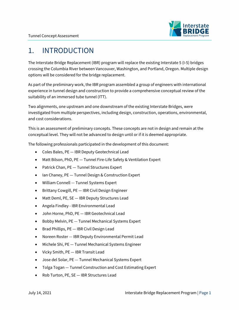
1. INTRODUCTION The Interstate Bridge Replacement (IBR) program will replace the existing Interstate 5 (I-5) bridges crossing the Columbia River between Vancouver, Washington, and Portland, Oregon. Multiple design options will be considered for the bridge replacement.
As part of the preliminary work, the IBR program assembled a group of engineers with international experience in tunnel design and construction to provide a comprehensive conceptual review of the suitability of an immersed tube tunnel (ITT).
Two alignments, one upstream and one downstream of the existing Interstate Bridges, were investigated from multiple perspectives, including design, construction, operations, environmental, and cost considerations.
This is an assessment of preliminary concepts. These concepts are not in design and remain at the conceptual level. They will not be advanced to design until or if it is deemed appropriate.
The following professionals participated in the development of this document:
• Coles Bales, PE — IBR Deputy Geotechnical Lead
• Matt Bilson, PhD, PE — Tunnel Fire-Life Safety & Ventilation Expert
• Patrick Chan, PE — Tunnel Structures Expert
• Ian Chaney, PE — Tunnel Design & Construction Expert
• William Connell — Tunnel Systems Expert
• Brittany Cowgill, PE — IBR Civil Design Engineer
• Matt Deml, PE, SE — IBR Deputy Structures Lead
• Angela Findley - IBR Environmental Lead
• John Horne, PhD, PE — IBR Geotechnical Lead
• Bobby Melvin, PE — Tunnel Mechanical Systems Expert
• Brad Phillips, PE — IBR Civil Design Lead
• Noreen Roster — IBR Deputy Environmental Permit Lead
• Michele Shi, PE — Tunnel Mechanical Systems Engineer
• Vicky Smith, PE — IBR Transit Lead
• Jose del Solar, PE — Tunnel Mechanical Systems Expert
• Tolga Togan — Tunnel Construction and Cost Estimating Expert
• Rob Turton, PE, SE — IBR Structures Lead
Tunnel Concept Assessment
July 14, 2021 Interstate Bridge Replacement Program | Page 2
Tunnel Concept Assessment
July 14, 2021 Interstate Bridge Replacement Program | Page 3
2. DESIGN CONSIDERATIONS The IBR program will replace the existing I-5 bridges crossing the Columbia River between Vancouver, Washington, and Portland, Oregon. In addition to vehicular traffic, the conceptual tunnel facility explored here would also accommodate high-capacity transit (HCT) and a multi-use path (MUP).
Two types of tunnels are typically considered for crossing below bodies of water. One is a bored tunnel where the tunnel is constructed using a tunnel boring machine. Given the length, size, and soil conditions present at this location, a bored tunnel is not appropriate. The other type is an ITT in which a series of prefabricated tunnel segments are constructed in a casting basin or on dry docks, and then sunk onto a prepared soil substrate. Tunnel segments are then connected underwater and the tunnel is dewatered. An ITT is assumed for this assessment.
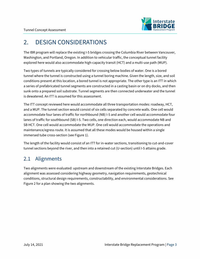
The ITT concept reviewed here would accommodate all three transportation modes: roadway, HCT, and a MUP. The tunnel section would consist of six cells separated by concrete walls. One cell would accommodate four lanes of traffic for northbound (NB) I-5 and another cell would accommodate four lanes of traffic for southbound (SB) I-5. Two cells, one direction each, would accommodate NB and SB HCT. One cell would accommodate the MUP. One cell would accommodate the operations and maintenance/egress route. It is assumed that all these modes would be housed within a single immersed tube cross-section (see Figure 1).
The length of the facility would consist of an ITT for in-water sections, transitioning to cut-and-cover tunnel sections beyond the river, and then into a retained cut (U-section) until I-5 attains grade.
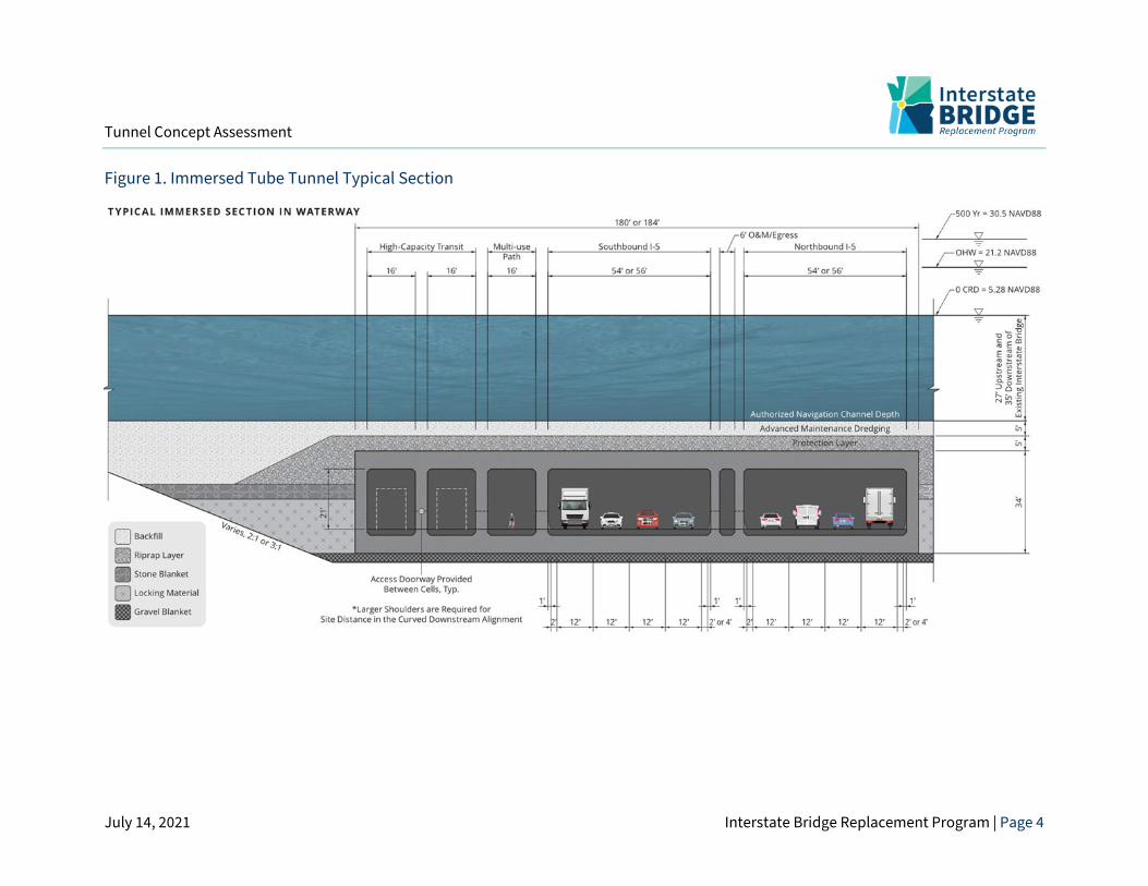
2.1 Alignments Two alignments were evaluated: upstream and downstream of the existing Interstate Bridges. Each alignment was assessed considering highway geometry, navigation requirements, geotechnical conditions, structural design requirements, constructability, and environmental considerations. See Figure 2 for a plan showing the two alignments.
Tunnel Concept Assessment
July 14, 2021 Interstate Bridge Replacement Program | Page 4
Figure 1. Immersed Tube Tunnel Typical Section
Tunnel Concept Assessment
July 14, 2021 Interstate Bridge Replacement Program | Page 5
Figure 2. Uptream and Downstream Tunnel Alignments
Tunnel Concept Assessment
July 14, 2021 Interstate Bridge Replacement Program | Page 6
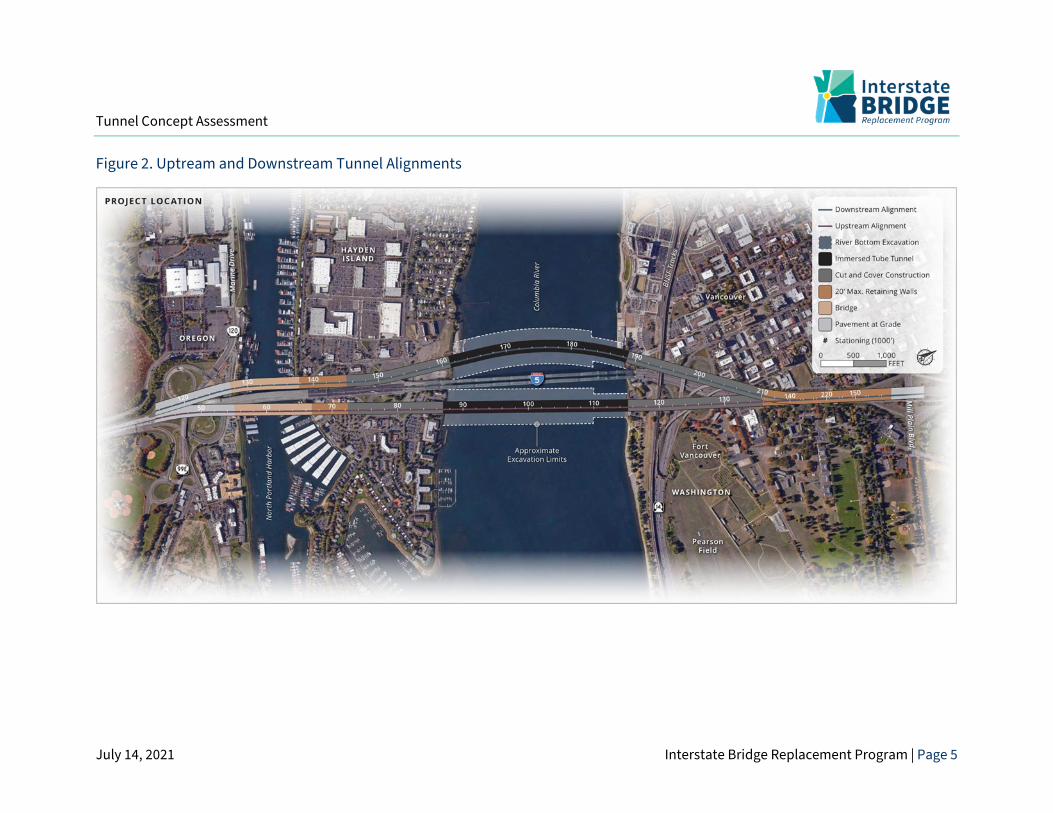
2.2 Columbia River Navigation Operational requirements for vessel navigation on the Columbia River define how deep a tunnel must be as it crosses below the Columbia River.
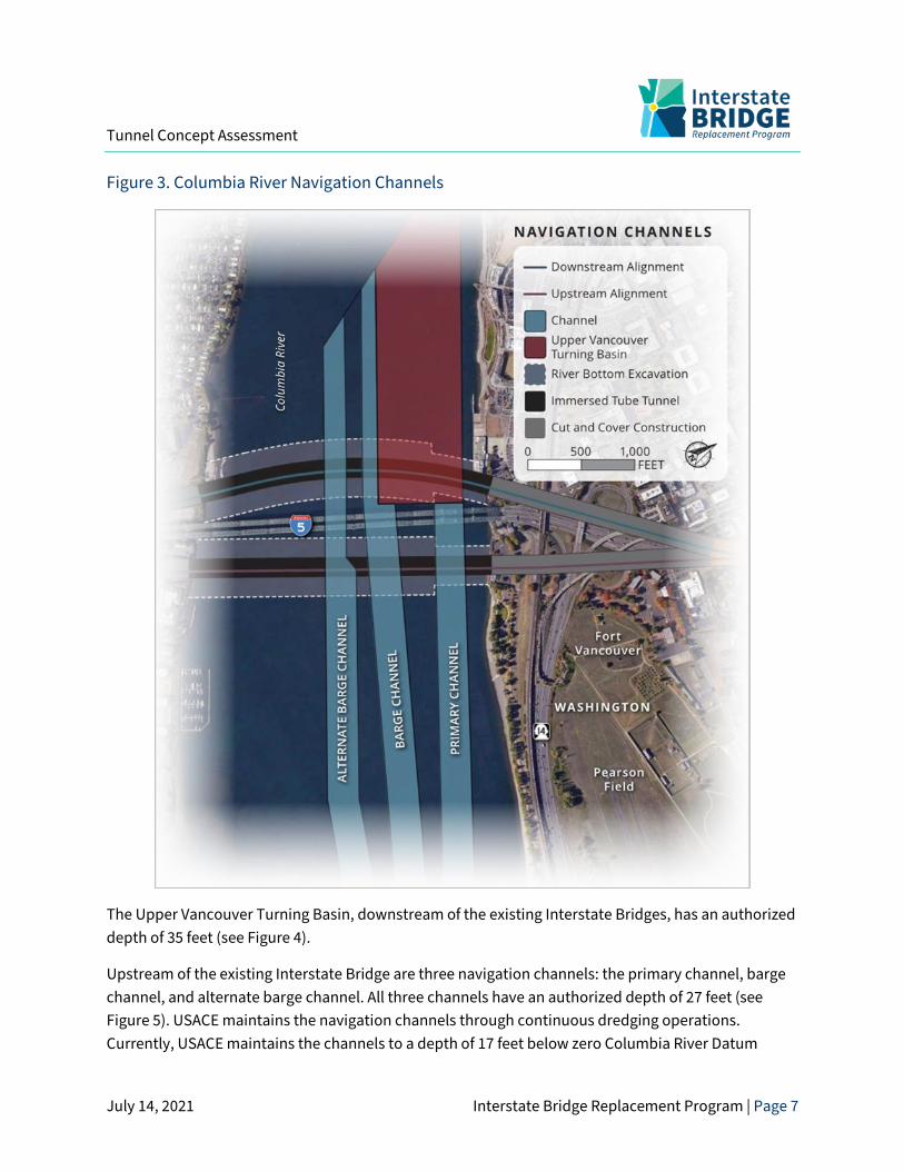
The United States Army Corps of Engineers (USACE) maintains the navigation channels on the Columbia River. River navigation features are authorized to specific locations, widths, and depths, as shown in Figure 3. Navigation features differ upstream and downstream of the existing Interstate Bridges.
Tunnel Concept Assessment
July 14, 2021 Interstate Bridge Replacement Program | Page 7
Figure 3. Columbia River Navigation Channels
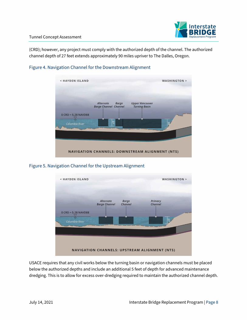
The Upper Vancouver Turning Basin, downstream of the existing Interstate Bridges, has an authorized depth of 35 feet (see Figure 4).
Upstream of the existing Interstate Bridge are three navigation channels: the primary channel, barge channel, and alternate barge channel. All three channels have an authorized depth of 27 feet (see Figure 5). USACE maintains the navigation channels through continuous dredging operations. Currently, USACE maintains the channels to a depth of 17 feet below zero Columbia River Datum
Tunnel Concept Assessment
July 14, 2021 Interstate Bridge Replacement Program | Page 8
(CRD); however, any project must comply with the authorized depth of the channel. The authorized channel depth of 27 feet extends approximately 90 miles upriver to The Dalles, Oregon.
Figure 4. Navigation Channel for the Downstream Alignment
Figure 5. Navigation Channel for the Upstream Alignment
USACE requires that any civil works below the turning basin or navigation channels must be placed below the authorized depths and include an additional 5 feet of depth for advanced maintenance dredging. This is to allow for excess over-dredging required to maintain the authorized channel depth.
Tunnel Concept Assessment
July 14, 2021 Interstate Bridge Replacement Program | Page 9
Below the advanced maintenance dredging depth, a 5-foot protective layer of rip rap would be required (see Figure 1). The rip rap layer would protect the ITT from unintended additional dredge excavation, sunken vessels, dragging anchors, river scour, and other hazards that could be detrimental to the structural section of the ITT.
2.3 Highway Design Two mainline I-5 alignments were evaluated; one upstream of the existing Interstate Bridges and one downstream. Both alignments were established to minimize impacts to the existing Interstate Bridges and facilitate construction phasing.
The ITT depth would be controlled by the authorized depths of the statutory Columbia River navigation channels. Maximum grades for the tunnel would be approximately 4.5%, controlled by highway design requirements. (This exceeds the maximum interstate grade of 4% prescribed by the departments of transportation. However, 4.5% grades can still accommodate the HCT and MUP.) A design speed of 60 miles per hour is assumed for both alignments. At the south end of the facility for both alignments, I-5 would attain grade near the south shore of Hayden Island. At the north end of the facility for both alignments, I-5 would attain grade near Evergreen Boulevard (see Figure 2).
Shoulder widths in the facility are assumed to be 2 to 4 feet wide (see Figure 1). This would require a design exception from the Oregon and Washington departments of transportation, but these widths are typical of similar proposed and constructed tunnels currently in service.
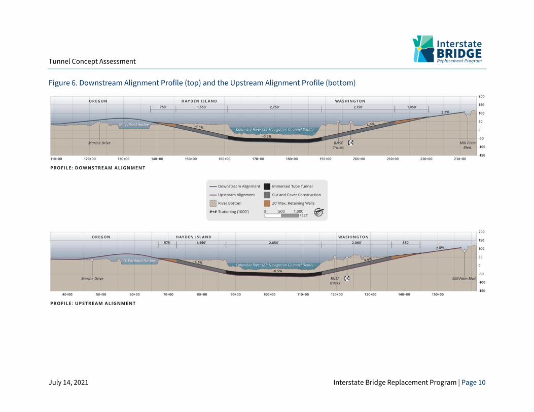
2.4 Downstream Alignment The downstream alignment as shown in Figure 2 would incorporate a horizontal curve to avoid temporary impacts to the existing Interstate Bridges during construction. This alignment would result in a portal-to-portal tunnel length of 6,450 feet. The grades associated with the downstream alignment are shown in Figure 6. Due to the horizontal curve, 4-foot shoulders would be required to accommodate site distance as shown in Figure 1.
A deeper excavation would be required for this alignment than for the upstream alignment.
Tunnel Concept Assessment
July 14, 2021 Interstate Bridge Replacement Program | Page 10
Figure 6. Downstream Alignment Profile (top) and the Upstream Alignment Profile (bottom)
Tunnel Concept Assessment
July 14, 2021 Interstate Bridge Replacement Program | Page 11
2.4.1 Upstream Alignment
The upstream alignment as shown in Figure 2 would follow a more direct route across the river with a shorter portal-to-portal length of 6,360 feet. The grades associated with this alignment are shown in Figure 5.
Due to the upstream USACE-authorized channel depths, this alignment would require less overall excavation. Refer to the Construction Considerations section for further details.
2.4.2 Interchanges
In this assessment of a conceptual ITT, interchanges were not addressed in detail. However, interchanges at Hayden Island, downtown Vancouver, and State Route (SR) 14 would require unconventional and complex below-grade construction. For example, at the center of Hayden Island, I-5 would be 34 feet below grade for the upstream alignment and 38 feet below grade for the downstream alignment. Where I-5 intersects SR-14, I-5 would be 71 feet below grade for the upstream alignment and 73 feet below grade for the downstream alignment (see Figure 5).
The only way to provide connectivity would be to construct cut-and-cover tunnels for ramps to achieve the required interchange connections. The ramp geometry required to accomplish this has not been verified. Large temporary excavations would be required to construct the cut-and-cover ramps. This type of construction is not typical and would have operational implications that are addressed in Chapter 4, Operational Considerations.
2.5 High-Capacity Transit HCT, regardless of whether it is bus rapid transit (BRT) or light rail transit (LRT), would be accommodated at the 4.5% grades established for the highway profiles. (LRT has a maximum recommended grade of 5%.)
2.5.1 Multi-Use Path
The MUP can have a maximum sustained grade of 5%, which would be accommodated by the grades shown on the highway profiles. The MUP would be in a tunnel section for the entire portal-to-portal lengths described above.
Tunnel Concept Assessment
July 14, 2021 Interstate Bridge Replacement Program | Page 12
2.6 Aviation The ITT would result in removal of the obstruction caused by the existing iInterstate Bridges and would not impact permanent operations at Pearson Field or Portland International Airport.
2.7 Geotechnical Considerations
2.7.1 Regional Geology
The project area is located within the Portland Basin, approximately 5 miles east of the confluence of the Columbia River and the Willamette River. The Portland Basin is a northwest-trending structural basin, roughly 40 miles in length and 20 miles in width, flanked by the Tualatin Mountains to the west and the Cascade foothills to the east. The basin is underlain by sequences of lava flows of the Columbia River Basalt Group (CRBG).
During and following the period of extensive lava flows forming the CRBG (ca. 17 to 6 million years ago), the Portland Basin subsided and Sandy River Mudstone and Troutdale Formation were deposited [primarily] by the ancestral Columbia River. Troutdale Formation conformably overlies Sandy River Mudstone and may be up to 400 feet thick in some locations. The Troutdale Formation has been variably eroded by the ancestral Columbia and Willamette Rivers, and by a series of late Pleistocene glacial outburst floods which deposited up to 200 feet of sediment ranging from silts and sands with occasional clay interbeds (fine-grained facies) to gravels and boulders (coarse-grained facies). Following the last of the catastrophic glacial outburst floods, the sea level rose and the deep channels of the Columbia River were infilled with silty/sandy alluvium and broad floodplains were formed along the Columbia River.
2.7.2 Seismicity and Faulting
The regional seismicity is largely driven by proximity to an active convergent-plate boundary. This zone, called the Cascadia Subduction Zone (CSZ), is a broad, eastward-dipping zone of contact between the upper portion of the subducting slabs of the Gorda, Juan de Fuca, and Explorer plates and the overriding North American plate. Regional seismicity associated with the CSZ includes mega-thrust interface events as well as deeper intraslab events.
Local seismicity is generally driven by shallow crustal sources in the vicinity of or within the Portland Basin. The Portland Basin is bounded by high-angle, northwest-trending, right-lateral strike-slip faults considered to be seismogenic; however, the relationship between specific earthquakes and individual faults in the area is not well understood since few of these faults are expressed clearly at the ground surface and the foci of the observed earthquakes have not been located with precision.
Tunnel Concept Assessment
July 14, 2021 Interstate Bridge Replacement Program | Page 13
2.7.3 Geologic Units
Fill
Fill materials are only anticipated to be encountered near the shoreline and where excavations extend beyond the banks of the river. The fill materials include loose to medium dense, clean to silty, sand to gravel with some wood and other debris, consistent with the historical development and frequent, local modifications to facility use type and operation.
Sand/Silt Alluvium
Sand/silt alluvium is anticipated to be present in nearly all excavation and dredging operations extending from the south end of the proposed alignments to within about 500 feet of the north riverbank. These materials include very soft/loose to stiff/dense silts and sands that are frequently interbedded and generally non-plastic to low plasticity.
Gravel Alluvium
Gravel alluvium is anticipated to be present in excavation and dredging operations extending from about 500 feet south of the north riverbank and continuing to the north. These materials include gravels with variable amounts of silt and sand, and sometimes appear as openwork gravels. This unit is documented as containing scattered cobbles and boulders.
Troutdale Formation
Troutdale may be present for a short distance at the base of dredging operations between about 1,000 feet and 500 feet south of the north riverbank. These materials may appear as a weakly to moderately cemented conglomerate which comprises gravels within a sand and silt matrix. Similar to the gravel alluvium, this unit is documented as containing scattered cobbles and boulders.
2.7.4 Geologic Hazards
Ground Shaking
An ITT would need to be designed to withstand the transient strains associated with ground shaking. Tunnels are regularly designed to account for ground behavior during a seismic event.
Liquefaction
Previous geotechnical studies conducted in this location found that saturated fill materials and silt/sand alluvium are likely susceptible to excess pore pressure development leading to liquefaction-
Tunnel Concept Assessment
July 14, 2021 Interstate Bridge Replacement Program | Page 14
induced strength loss, settlement and lateral spreading during a design seismic event. To mitigate against liquefaction effects, most particularly the potential for differential liquefaction-induced settlements along the tunnel alignment, it is expected that some level of ground improvement may be required. A discussion of ground improvement is provided in the Construction Considerations section.
2.8 Structural Design A preliminary structural design was developed for the ITT cross-section. Dimensions of the section considered in-service loading and temporary conditions as the section is floated out and placed. The general arrangement and dimensions are shown in Figure 1.
The maximum interior clear height is assumed to be 21 feet with equipment niches of up to an additional 2 feet to allow for ventilation, fire suppression, signage, and lighting while maintaining the required vertical clearance of 17 feet, 4 inches. The 2-foot equipment niches are located in the cut-and-cover sections of the facility.
2.8.1 Preliminary Analysis
Based on experience, the required structural dimensions are most often controlled by the transverse cross-sectional analysis. Because of this, a longitudinal analysis was not performed at this preliminary stage. A transverse analysis was performed for the cross-section. The section was checked for strength and service loads for moment, axial force, and shear demands, showing that the conceptual section depicted in Figure 1 is adequate.
ITTs can be subjected to several extreme load cases. These load cases are typically checked during later stages of design and were thus not checked as part of this conceptual assessment. These load cases include ship anchors, ship sinking and grounding, heat effects associated with a design fire, explosion, tunnel flooding, and loss of support during construction.
This cross-section (see Figure 1) allows for a buoyant condition during transport and would achieve an acceptable factor of safety against buoyancy during immersion.
Tunnel Concept Assessment
July 14, 2021 Interstate Bridge Replacement Program | Page 15
3. CONSTRUCTION CONSIDERATIONS The following sections identify considerations associated with construction of a tunnel facility. Focus is primarily on construction of the ITT section of the facility and the interfaces with the cut-and-cover sections on Hayden Island and in Vancouver.
3.1 Dredging and Excavation Prior to placement of the ITT segments, a trapezoidal channel would be dredged, with the base of the trapezoid wider than the base of the immersed tunnel segment and side slopes laid back to prevent sloughing or raveling. Table 1 shows the anticipated preliminary excavation quantities on Hayden Island, in the Columbia River, and in Vancouver for the full cross-section shown in Figure 1.
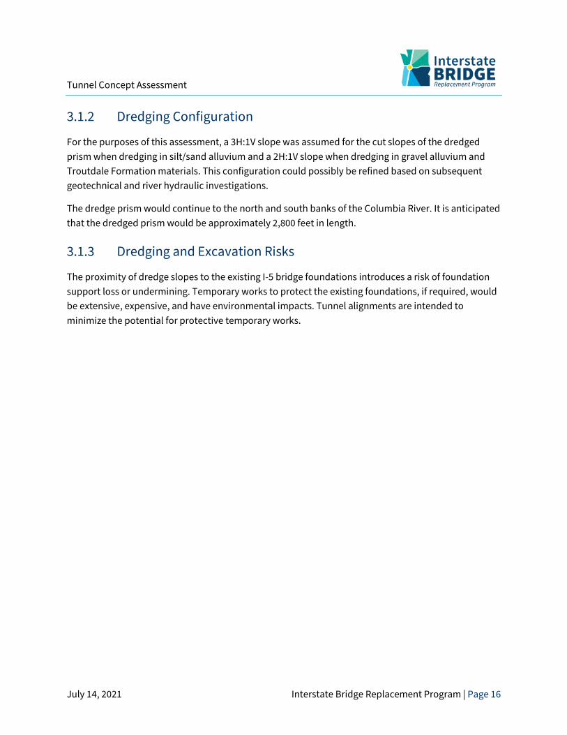
Some of the dredged materials would typically be used as backfill over the rip rap protection layer. However, much of the excavated material would be replaced by engineered fill designed to protect the tunnel from scour and potential impacts, as well as to provide tunnel support both during construction and a potential seismic event. Figure 7 shows a cross-section of the conceptual dredge prism for the ITT across the Columbia River.
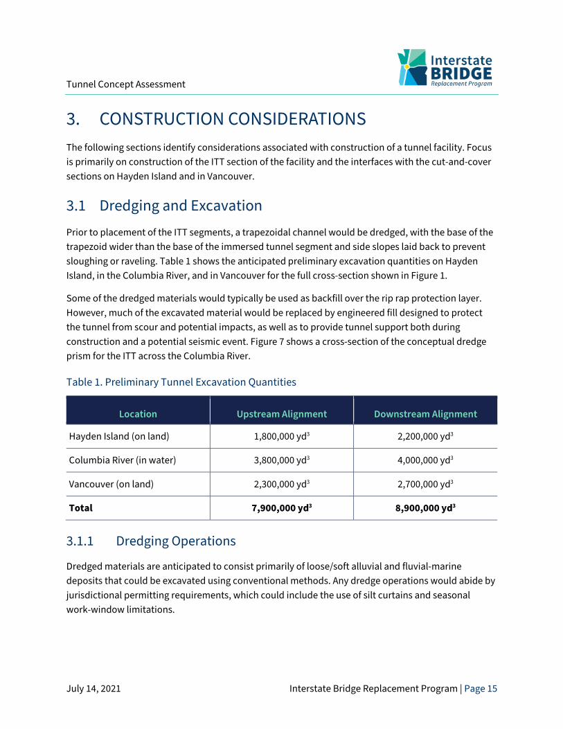
Table 1. Preliminary Tunnel Excavation Quantities
Location Upstream Alignment Downstream Alignment
Hayden Island (on land) 1,800,000 yd3 2,200,000 yd3
Columbia River (in water) 3,800,000 yd3 4,000,000 yd3
Vancouver (on land) 2,300,000 yd3 2,700,000 yd3
Total 7,900,000 yd3 8,900,000 yd3
3.1.1 Dredging Operations
Dredged materials are anticipated to consist primarily of loose/soft alluvial and fluvial-marine deposits that could be excavated using conventional methods. Any dredge operations would abide by jurisdictional permitting requirements, which could include the use of silt curtains and seasonal work-window limitations.
Tunnel Concept Assessment
July 14, 2021 Interstate Bridge Replacement Program | Page 16
3.1.2 Dredging Configuration
For the purposes of this assessment, a 3H:1V slope was assumed for the cut slopes of the dredged prism when dredging in silt/sand alluvium and a 2H:1V slope when dredging in gravel alluvium and Troutdale Formation materials. This configuration could possibly be refined based on subsequent geotechnical and river hydraulic investigations.
The dredge prism would continue to the north and south banks of the Columbia River. It is anticipated that the dredged prism would be approximately 2,800 feet in length.
3.1.3 Dredging and Excavation Risks
The proximity of dredge slopes to the existing I-5 bridge foundations introduces a risk of foundation support loss or undermining. Temporary works to protect the existing foundations, if required, would be extensive, expensive, and have environmental impacts. Tunnel alignments are intended to minimize the potential for protective temporary works.
Tunnel Concept Assessment
July 14, 2021 Interstate Bridge Replacement Program | Page 17
Figure 7. Estimated Excvation for ITT Construction
Tunnel Concept Assessment
July 14, 2021 Interstate Bridge Replacement Program | Page 18
3.1.4 Shoreline Excavation
Excavation support would be required to facilitate excavations for the transition from the immersed tunnel segments to the cut-and-cover and retained cut segments. Support for excavations outside of the river would likely consist of sheet pile wall shoring systems that are anchored, braced, or some combination of the two. Potential conflicts between anchors and adjacent subsurface infrastructure were not evaluated as part of this assessment.
3.2 Ground Improvement Ground improvement may be required to mitigate against liquefaction effects. Several ITTs designed and constructed in the recent past have included ground improvement programs to mitigate against these effects, such as stone columns for the Aktio-Preveza Tunnel (Greece) and the Limerick Tunnel (Ireland) or compaction grouting for the Marmaray Tunnel (Turkey). For the New George Massey Tunnel (Canada), multiple ground improvement options are being considered, including stone columns beneath the tunnel and cut-off walls on the sides of the new tunnel (to resist lateral spreading type deformations, limit the potential for interaction between the new and an existing tunnel, and limit the dredging footprint).
Any ground improvement program would need to consider and mitigate against the potential for adverse impacts during construction, including both environmental impacts and impacts to the existing Interstate Bridges. For example, grouting-type programs include the risk of cementitious material release into the river and displacement/replacement methods require vibration to advance a probe into the subsurface materials.
3.3 ITT Construction
3.3.1 Segment Fabrication
ITT segments are typically constructed in dry docks or casting basins adjacent to a navigable waterway. Many immersed tunnel projects have required the development of dedicated casting facilities designed specifically for the project, such as for the Fehmarnbelt Tunnel project (Denmark/Germany), though some have been able to utilize existing dry-dock facilities such as the Elizabeth River Tunnels project (Virginia). The cost to develop a project-specific casting facility is typically quite high. However, project constraints can often make this the only practical solution due to lack of adequate existing facilities and/or navigation challenges.
Due to the lack of suitable facilities in the region, it is expected that a new casting facility would need to be designed and constructed specifically for this project. Potential sites for a new casting facility
Tunnel Concept Assessment
July 14, 2021 Interstate Bridge Replacement Program | Page 19
were not identified as part of this assessment. It is recommended that any new casting facility developed for this project be sized to accommodate the simultaneous fabrication of multiple ITT segments as temporary float storage of segments and/or significant downtime between placement of immersed segments can increase project costs and risks.
3.3.2 Segment Delivery
The delivery of the tunnel segments would require coordination with private and public entities in the region to ensure navigation requirements were adhered to. Additionally, seasonal constraints, such as river levels, flow velocities, and in-water work windows, would need to be considered.
3.3.3 Segment Placement and Connection
After dredging is completed, a level bedding layer of gravel would be placed. The tunnel segments would be ballasted and lowered. Once the tunnel segments are aligned and set at the proper grade, any void space between the base of the segments and the gravel layer would be filled. When these phases are complete and an initial seal between tunnel segments is established, the water within the sealed zone between segments would be pumped out for construction of a final seal and structural connections.
3.3.4 Segment Cover and Backfill
The proper placement of lateral support and vertical protection and restraint materials is integral to the performance of the ITT. Lateral support is generally derived from keying/locking materials that compact naturally and that would remain stable under seismic conditions. The keying/locking materials and the tunnel segments would be covered with a blanket of well-graded stones followed by rip rap armoring to further lock the segment in place and provide protection against potential impact loads.
3.4 Cut-and-Cover and Retained Cut Construction The ITT would be connected to the above-ground roadway network via cut-and-cover and retained cut connections at either end. Excavation support for these end connections could differ between Vancouver and Hayden Island, as excavations in Vancouver are anticipated to be primarily in gravel alluvium, whereas excavations on Hayden Island are anticipated to be primarily in silt/sand alluvium. The deepest excavations could require ground support systems consisting of braced or restrained secant pile or slurry walls, while shallower excavations may require less robust ground support systems. Ground improvement measures could be incorporated to decrease the potential for seepage
Tunnel Concept Assessment
July 14, 2021 Interstate Bridge Replacement Program | Page 20
through the base of the excavation and to provide long-term support for the constructed cut-and-cover and retained cut sections.
3.5 BNSF Railroad Coordination Temporary shoring would be required to excavate and construct the cut-and-cover sections through Vancouver, including below the existing BNSF Railroad berm and tracks. Two methods of constructing the cut-and-cover tunnel below the BNSF tracks were considered. Both methods would require extensive coordination and permitting with BNSF.
The first would be a jacking procedure in which all or portions of the ITT cross-section would be advanced below ground using hydraulic jacks and a reaction structure.
The second method would reroute the existing tracks via temporary tracks, or a “shoo-fly” for the duration of construction. The cut-and-cover section could then be excavated and constructed in the BNSF right-of-way before the tracks would be restored over the newly constructed tunnel. There is limited right-of-way to accommodate a shoo-fly.
3.6 Traffic Staging During construction, I-5 maintenance of traffic would require complex staging, particularly south of Evergreen Boulevard in the vicinity of the historic post hospital, where the retained cut section attains grade. To maintain traffic during construction, additional right-of-way west of I-5 could be required.
Tunnel Concept Assessment
July 14, 2021 Interstate Bridge Replacement Program | Page 21
4. OPERATIONAL CONSIDERATIONS Tunnel facilities require an extensive variety of operating systems to support safe traffic operation and provide for life safety of motorists and emergency responders. The following sections address the systems required for traffic operation and fire/life safety. Information is presented based on the mode: highway, HCT, and MUP.
4.1 Highway It is assumed that hazardous cargos would be permitted for this route. Hazardous cargos are normally banned from road tunnels, as the potential fire size is an extreme risk to both life safety and the facility itself. However, I-5 is an integral part of the Western US freight corridor. The fire size for a gasoline tanker can escalate to full heat release rate in a matter of minutes, creating a situation that is difficult, if not impossible, to manage or contain in terms of smoke control, firefighting, spill capture, and structural protection.
Certain elements of the fire protection and life safety systems have significant spatial requirements. Feasible concepts for these systems have been assessed to ensure that the conceptual tunnel structure has adequate space to accommodate them. Fire protection and life safety system elements with spatial impacts include:
• Emergency ventilation system
• Fixed fire suppression system
• Tunnel drainage system
• Emergency egress
The primary national standard for fire protection systems in road tunnels is NFPA 502, Standard for Road Tunnels, Bridges, and Other Limited Access Highways. The standard provides performance goals and general guidance for fire protection design.
For a tunnel of this length (6,500 feet, Category D), NFPA 502 mandates the following minimum road tunnel fire protection requirements:
• Emergency ventilation system sized to meet minimum ventilation requirements with one fan out of service or providing operational measures to ensure that life safety is not compromised with one fan out of service.
• Fire protection of structural elements. The structure shall be able to withstand the temperature exposure represented by the Rijkswaterstaat time-temperature curve or other recognized time-temperature curve approved by the authority having jurisdiction (AHJ), following an engineering analysis.
Tunnel Concept Assessment
July 14, 2021 Interstate Bridge Replacement Program | Page 22
• Fire alarm control panel and detection, identification, and location of fire in the tunnel.
• Fire standpipe designed and installed in accordance with NFPA 14.
• Fire hose valve connections are required so that no location on the tunnel is more than 150 feet from a hose connection.
• An emergency power system in accordance with Article 700 of NFPA 70 is required, and it shall provide power to all major tunnel systems, including the ventilation system.
• Tunnel drainage collection system designed so that spills of hazardous and flammable liquids cannot spread or cause flame propagation.
The following requirements are conditionally mandatory pending the results of an engineering analysis:
• Water-based fire-fighting system
• Closed-circuit television and automatic fire detection systems
The tunnel would need to accommodate a variety of operational systems and features to support safe traffic operations and to provide the necessary level of fire protection and life safety, including:
• Emergency egress
• Normal and emergency tunnel ventilation
• Fixed firefighting system and fire standpipe
• Fire detection and alarm
• Emergency communications
• Roadway drainage
• Normal and emergency electrical power
• Supervisory control and data acquisition (SCADA)
• Roadway lighting
• Traffic control and monitoring
• Tunnel finishes and special signage
• Operations and maintenance
4.1.1 Highway Egress
The egress strategy would be a fire-rated corridor (cell) that runs between the NB and SB I-5 cells. The door spacing must be 1,000 feet or less; 600 feet is typical. Suitable emergency signage, lighting, and pressurization of the fire-rated corridor is also required.
Tunnel Concept Assessment
July 14, 2021 Interstate Bridge Replacement Program | Page 23
The egress corridor should have a width of 6 feet to accommodate drainage pipes, water mains, and other services. The space above the egress envelope would house these items.
4.1.2 Highway Ventilation
Ventilation is required for normal operations (vehicle emissions management) and emergency operations (smoke management). NFPA 502 requires tenable conditions for egress and facilitation of conditions for firefighting. Achieving these conditions relies on ventilation, means of egress, and fire control. Based on the tunnel length and traffic configuration, a longitudinal ventilation system is recommended for this facility.
Portal emissions and air quality compliance in surrounding areas would be critical with a longitudinal ventilation system. If acceptable air quality cannot be achieved or maintained, then ventilation buildings at each portal would be required.
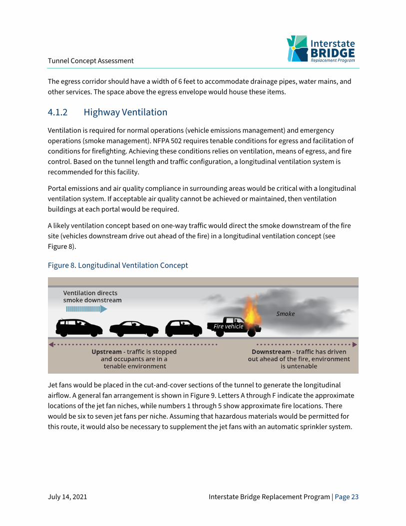
A likely ventilation concept based on one-way traffic would direct the smoke downstream of the fire site (vehicles downstream drive out ahead of the fire) in a longitudinal ventilation concept (see Figure 8).
Figure 8. Longitudinal Ventilation Concept
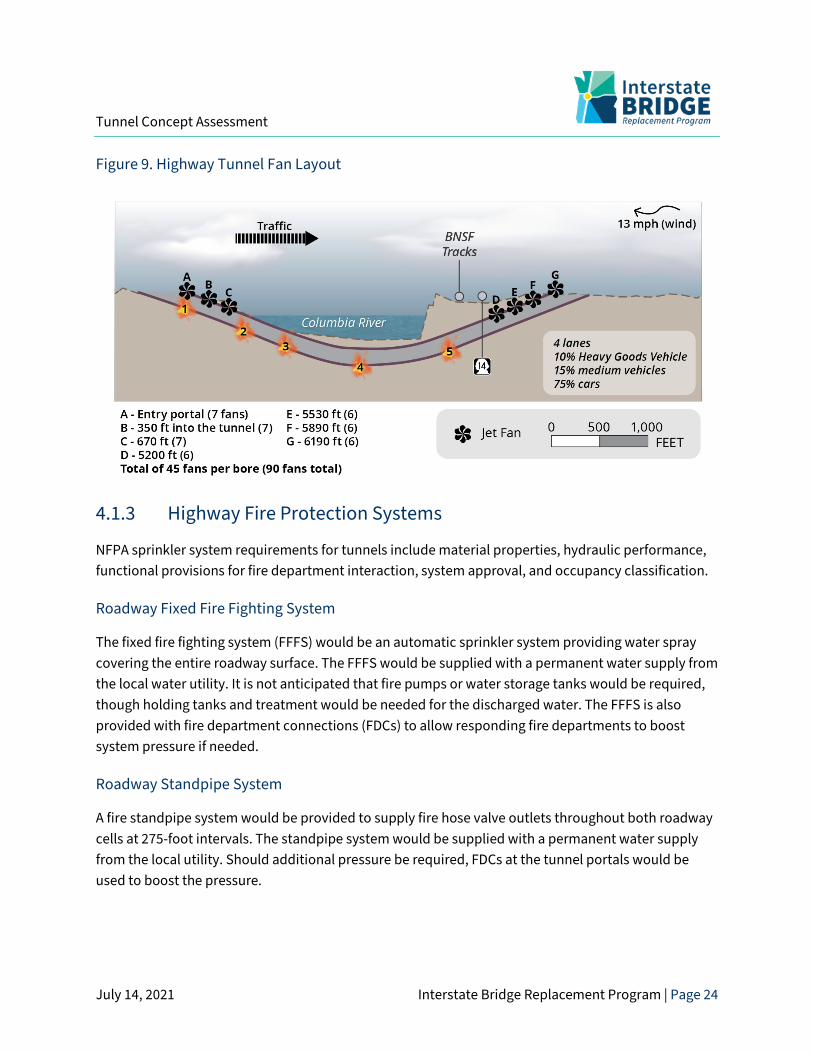
Jet fans would be placed in the cut-and-cover sections of the tunnel to generate the longitudinal airflow. A general fan arrangement is shown in Figure 9. Letters A through F indicate the approximate locations of the jet fan niches, while numbers 1 through 5 show approximate fire locations. There would be six to seven jet fans per niche. Assuming that hazardous materials would be permitted for this route, it would also be necessary to supplement the jet fans with an automatic sprinkler system.
Tunnel Concept Assessment
July 14, 2021 Interstate Bridge Replacement Program | Page 24
Figure 9. Highway Tunnel Fan Layout
4.1.3 Highway Fire Protection Systems
NFPA sprinkler system requirements for tunnels include material properties, hydraulic performance, functional provisions for fire department interaction, system approval, and occupancy classification.
Roadway Fixed Fire Fighting System
The fixed fire fighting system (FFFS) would be an automatic sprinkler system providing water spray covering the entire roadway surface. The FFFS would be supplied with a permanent water supply from the local water utility. It is not anticipated that fire pumps or water storage tanks would be required, though holding tanks and treatment would be needed for the discharged water. The FFFS is also provided with fire department connections (FDCs) to allow responding fire departments to boost system pressure if needed.
Roadway Standpipe System
A fire standpipe system would be provided to supply fire hose valve outlets throughout both roadway cells at 275-foot intervals. The standpipe system would be supplied with a permanent water supply from the local utility. Should additional pressure be required, FDCs at the tunnel portals would be used to boost the pressure.
Tunnel Concept Assessment
July 14, 2021 Interstate Bridge Replacement Program | Page 25
Structural Thermal Protection System
The extreme temperatures possible in a tunnel fire can do extensive damage to a tunnel’s structural elements. Thermal protective board or other protective insulation would be required.
4.1.4 Highway Drainage Systems
Tunnel drainage systems normally consist of two independent systems: a stormwater control system and a tunnel drainage system. Stormwater control systems would be required at the tunnel portals to intercept stormwater flows that accumulate on the open approaches and transition roadways leading into and out of the tunnel. A separate tunnel drainage system, independent of inflow from sources outside the tunnel, would be required to collect and discharge water and effluents generated within the tunnel. These effluent flows would result from tunnel washing, use of fire suppression systems, vehicle carryover, and some seepage. The tunnel drainage system would also have to accommodate a potential fuel or hazardous material spill.
The profile of the selected tunnel alignment would dictate the tunnel’s low point. A drainage pump station would be required at this location. Systems would also be required for the MUP, HCT, and egress cells. The tunnel drainage effluent would require some form of pre-treatment prior to discharge depending on local permitting requirements.
4.1.5 Highway Electrical Systems
Several electrical operating systems would be necessary to support safe traffic operations. Tunnel electrical systems would include:
• Normal power distribution
• Emergency power distribution
• Fire alarm and detection
• Emergency communications
• Security
• SCADA
• Communication systems
4.1.6 Highway Lighting Systems
The tunnel lighting system would provide the required illumination so that a motorist could safely navigate and maintain speed while in the tunnel. This objective must be met during daytime, nighttime, and during an emergency (loss of power). Daylight conditions require high levels of
Tunnel Concept Assessment
July 14, 2021 Interstate Bridge Replacement Program | Page 26
illumination at the tunnel’s entry portals. Nighttime lighting levels are lower. During an emergency, lighting would be maintained at the nighttime level to allow for egress.
4.1.7 Traffic Control and Monitoring Systems
Roadway tunnels require a means for control of traffic within the tunnel, as well as traffic on the approach roadways leading into the tunnel. The types of traffic control systems and devices would likely include:
• Automatic incident identification system
• Closed-circuit television
• Variable message signs
• Lane use/control signals
• Over-height vehicle detection
4.2 Transit The primary national standard for fire protection systems in underground trainways is NFPA 130. If LRT were selected as the HCT, these requirements would apply. (If BRT were selected as the HCT, NFPA 502 would apply; see Section 4.1 above.) NFPA 130 protection requirements include:
• Cross-passageways at a maximum spacing of 800 feet for egress
• An emergency power system for all tunnel systems
• Minimum clear walkway width of 24 inches for egress
The tunnel would need to accommodate a variety of systems to support safe operations, fire protection, and life safety. Various trainway tunnel systems would include:
• Emergency egress
• Tunnel ventilation
• Fire protection
• Tunnel drainage
• Electrical systems
• Tunnel lighting
• Tunnel finishes (fire protection)
• Operations and maintenance
Tunnel Concept Assessment
July 14, 2021 Interstate Bridge Replacement Program | Page 27
4.2.1 Transit Ventilation Systems
Ventilation is required for smoke management per NFPA 130. The design fire is representative of a fully engulfed railcar or bus.
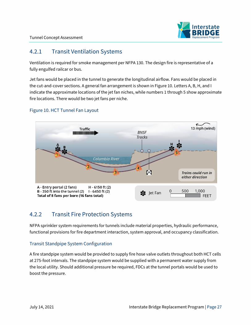
Jet fans would be placed in the tunnel to generate the longitudinal airflow. Fans would be placed in the cut-and-cover sections. A general fan arrangement is shown in Figure 10. Letters A, B, H, and I indicate the approximate locations of the jet fan niches, while numbers 1 through 5 show approximate fire locations. There would be two jet fans per niche.
Figure 10. HCT Tunnel Fan Layout
4.2.2 Transit Fire Protection Systems
NFPA sprinkler system requirements for tunnels include material properties, hydraulic performance, functional provisions for fire department interaction, system approval, and occupancy classification.
Transit Standpipe System Configuration
A fire standpipe system would be provided to supply fire hose valve outlets throughout both HCT cells at 275-foot intervals. The standpipe system would be supplied with a permanent water supply from the local utility. Should additional pressure be required, FDCs at the tunnel portals would be used to boost the pressure.
Tunnel Concept Assessment
July 14, 2021 Interstate Bridge Replacement Program | Page 28
4.3 Multi-Use Path The MUP cell would require lighting, ventilation, drainage, security, and fire and life-safety systems.
Walkways and bikeways in tunnels are not uncommon, but there are no known MUPs in facilities of this length. Egress with respect to smoke management would need to allow people downstream of the fire enough time to reach an egress point. This is of particular concern because any doors from the MUP would lead either to the transit or roadway cells, creating a security and safety risk.
Based on experience, a ventilation system similar to that proposed for the transit tunnel would likely be enough to provide sufficient fresh air. Supply air would be provided via jet fans.
4.4 Operations and Maintenance A comprehensive operations and maintenance program is necessary to ensure a safe, well-maintained, and reliable tunnel facility. The program would include emergency management plans, maintenance management plans, and operational procedure manuals.
A staffed operations center would be required for monitoring the mechanical, electrical, traffic control systems, and security. A tunnel system support building would be required at each end of the tunnel to house electrical distribution equipment, communications equipment, intelligent transportation system equipment, ventilation systems, fire systems, etc.
Additional facilities may include maintenance shops, garages, and storage spaces to house equipment and spare parts.
An operational ITT would require a full-time staff. A mix of personnel would be required, including electricians, mechanics, millwrights, and general maintenance staff to maintain the facilities and various systems.
Tunnel Concept Assessment
July 14, 2021 Interstate Bridge Replacement Program | Page 29
5. ENVIRONMENTAL CONSIDERATIONS This section provides a general overview of the environmental considerations associated with a tunnel alternative.
5.1 Biological • In-water trenching during construction would disturb the river bottom across the entire
width of the Columbia River, including the riverbanks. • Dredged material would need to be placed in an in-water or upland site and may require
special handling if contaminated materials are found. • Disturbance to the river bottom and nearshore habitat would require mitigation. • In-water construction would impact aquatic plants, fish, marine mammals, and birds. • The tunnel would eliminate over-water shading.
5.2 Hazardous Material • Excavation would cause disturbance and suspension of potentially contaminated
sediment in the Columbia River. • Large excavations required on land would potentially encounter contaminated soils
requiring treatment and/or disposal in approved facilities. • The volume of potentially contaminated material associated with tunnel excavation may
exceed the capacity of existing disposal locations.
5.3 Historic Structures and Archaeological • Historic structures and archaeological resources may be disturbed and permanently
impacted due to the size and volume of excavation required for the tunnel. • There are tribal concerns about burials along the Columbia River shoreline. • Construction vibration could cause impacts to historic structures and archeological
resources. • The tunnel could impact Fort Vancouver and the Old Apple Tree Park.
5.4 Land Use • Construction activities would impact businesses, neighborhoods, and parks and
recreation areas. These impacts would include construction noise, vibration, and additional traffic congestion.
Tunnel Concept Assessment
July 14, 2021 Interstate Bridge Replacement Program | Page 30
• Utility relocations would be required for the tunnel facility. • Tunnel right-of-way would require negotiation with BNSF for construction impacts and
temporary track reroutes. • A tunnel would provide opportunities for trail connectivity on the Washington shore and
increase the potential for more park space along the river. • The tunnel provides an unimpaired viewshed along the river.
5.5 Navigation and Aviation • A tunnel would not impact aviation operations at Pearson Field or Portland International
Airport. • The tunnel would eliminate navigation hazards in the river.
5.6 Permitting • In-water work windows and related work restrictions would impact the construction
schedule. • It is yet to be determined whether existing dredge spoil disposal sites could
accommodate the volume of sediment generated. • Permitting a new dredge spoil disposal site may not be feasible to complete within the
expected project schedule.
5.7 Safety and Emergency Response • The tunnel would impact emergency response routes on both sides of the river. • The MUP, which would be enclosed for over one mile, poses a safety concern for users.
5.8 Storm Water Management • Once constructed, the tunnel would require a continuously operating low-point sump
and pump system. The sump and pump system would require storm water retention and treatment facilities.
Tunnel Concept Assessment
July 14, 2021 Interstate Bridge Replacement Program | Page 31
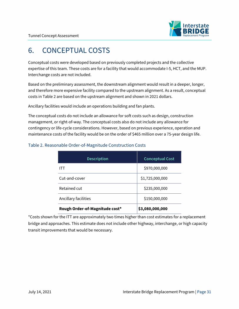
6. CONCEPTUAL COSTS Conceptual costs were developed based on previously completed projects and the collective expertise of this team. These costs are for a facility that would accommodate I-5, HCT, and the MUP. Interchange costs are not included.
Based on the preliminary assessment, the downstream alignment would result in a deeper, longer, and therefore more expensive facility compared to the upstream alignment. As a result, conceptual costs in Table 2 are based on the upstream alignment and shown in 2021 dollars.
Ancillary facilities would include an operations building and fan plants.
The conceptual costs do not include an allowance for soft costs such as design, construction management, or right-of-way. The conceptual costs also do not include any allowance for contingency or life-cycle considerations. However, based on previous experience, operation and maintenance costs of the facility would be on the order of $465 million over a 75-year design life.
Table 2. Reasonable Order-of-Magnitude Construction Costs
Description Conceptual Cost
ITT $970,000,000
Cut-and-cover $1,725,000,000
Retained cut $235,000,000
Ancillary facilities $150,000,000
Rough Order-of-Magnitude cost* $3,080,000,000
*Costs shown for the ITT are approximately two times higher than cost estimates for a replacement bridge and approaches. This estimate does not include other highway, interchange, or high capacity transit improvements that would be necessary.
Tunnel Concept Assessment
July 14, 2021 Interstate Bridge Replacement Program | Page 32
7. SUMMARY The following is a summary of the considerations associated with the ITT concept.
7.1 Design • Upstream and downstream tunnel alignments were considered.
• The facility would consist of an ITT for in-water sections, transitioning to cut-and-cover tunnel sections beyond the river and then into a retained cut (U-section) until I-5 attains grade.
• At the south end of the facility, I-5 would attain grade near the south shore of Hayden Island.
• At the north end of the facility, I-5 would attain grade near Evergreen Boulevard.
• The facility would consist of six cells: four lanes for NB I-5 and four lanes for SB I-5, a MUP, NB and SB HCT, and a maintenance/egress corridor. Each mode and direction are separated by a wall.
• Maximum grades for the tunnel would be approximately 4.5% controlled by highway design requirements.
• The ITT depth would be controlled by the authorized depths of the statutory Columbia River navigation channels.
• The ITT would be designed to meet current seismic safety standards.
• The combination of the controlling grades and the depth of the river channel would require interchange access modifications. Connectivity to Hayden Island, downtown Vancouver, and SR-14 would be extremely difficult and require unconventional construction below grade.
7.2 Constructability • Large excavations in excess of 70 feet deep at the Washington shoreline and in excess of 30
feet deep on Hayden Island would be required to facilitate construction of the cut-and-cover tunnel sections.
• The high groundwater and permeable soil would require extensive measures, such as temporary shoring and dewatering systems, to provide a suitably dry and stable excavation for construction of the cut-and-cover and retained cut sections.
• The proximity of in-water and on-land excavations to the existing Interstate Bridges’ foundations could require extensive temporary works to preserve the structural integrity of the existing bridges during ITT construction. The alignments considered sought to avoid this risk.
Tunnel Concept Assessment
July 14, 2021 Interstate Bridge Replacement Program | Page 33
• Washington excavations would require temporary relocation of the dual BNSF mainline tracks or complex staged and phased construction techniques.
• Maintenance of traffic on I-5 would require complex staging south of Evergreen Boulevard in the vicinity of the historic post hospital.
• Due to the lack of suitable facilities in the region, it is expected that a new casting facility would need to be developed.
7.3 Operations • The ITT would require an operations and maintenance/egress tunnel from end to end
between NB and SB I-5.
• Extensive fire and life safety systems would be required.
• The ITT would require a continuously operational low-point sump and pump system.
• Operations and maintenance equipment housing would be required at each end of the facility.
7.4 Environmental Considerations • In-water excavation would require approximately 4 million cubic yards of material. Total
excavation for the tunnel facility would be approximately 8 to 9 million cubic yards of material.
• In-water construction would impact aquatic plants, fish, marine mammals and birds.
• Excavations in the vicinity of SR-14 would likely encounter cultural resources.
• In-water work windows and related work restrictions would impact the construction schedule.
• A tunnel would not impact aviation operations at Pearson Field or Portland International Airport.
• The tunnel would eliminate navigation hazards in the river.

![CFD-AIDED TENABILITY ASSESSMENT OF RAILWAY TUNNEL …liuyl.tripod.com/pdf/Liu-CFD.pdf · CFD modelling and risk analysis [9]. However, publications on CFD assessment of railway tunnel](https://img.pdfslide.us/doc/110x75/5edd4206ad6a402d6668499c/cfd-aided-tenability-assessment-of-railway-tunnel-liuyl-cfd-modelling-and-risk.jpg)