Embed Size (px)
Citation preview
1
1
DEMO TITLES
Vector Control of Induction Motor Controllers design step by step
Author: Tshibain Tshibungu Simsmart Technologies Inc.
Brossard, Quebec Canada
Software used: Simsmart Engineering Suite V6 (ES V6)
A-PDF Merger DEMO : Purchase from www.A-PDF.com to remove the watermark
2
2
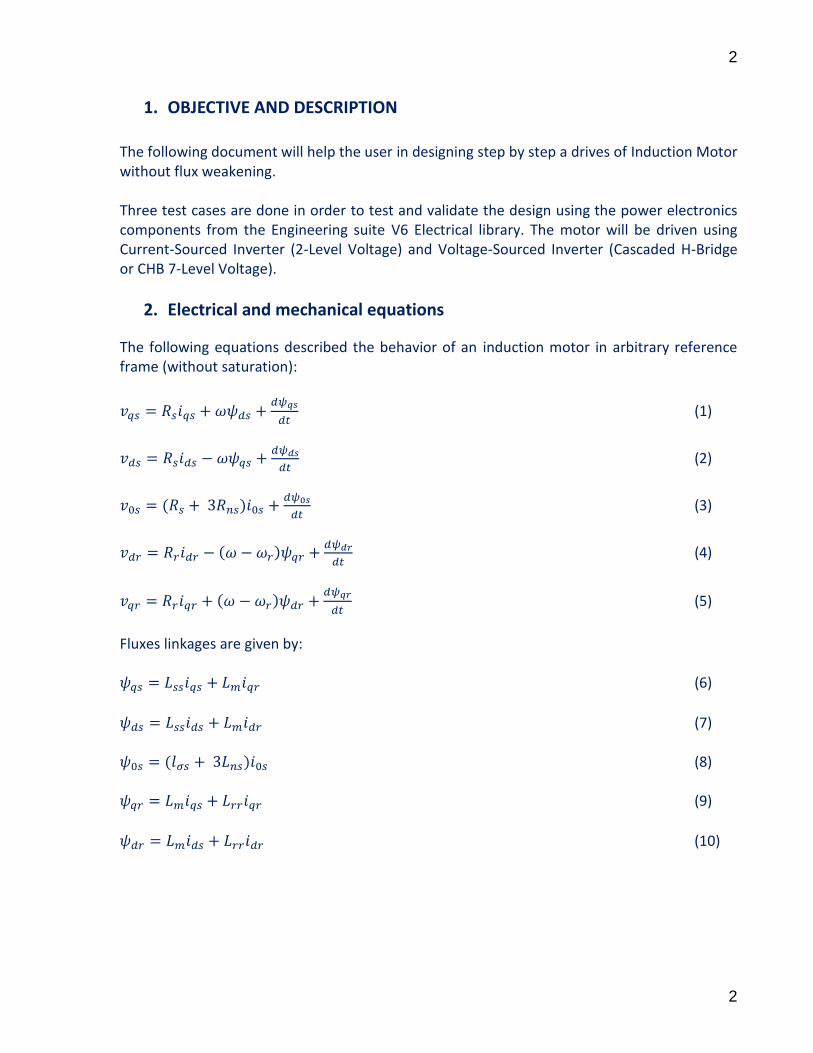
1. OBJECTIVE AND DESCRIPTION
The following document will help the user in designing step by step a drives of Induction Motor without flux weakening. Three test cases are done in order to test and validate the design using the power electronics components from the Engineering suite V6 Electrical library. The motor will be driven using Current-Sourced Inverter (2-Level Voltage) and Voltage-Sourced Inverter (Cascaded H-Bridge or CHB 7-Level Voltage).
2. Electrical and mechanical equations
The following equations described the behavior of an induction motor in arbitrary reference frame (without saturation):
(1)
(2)
(3)
(4)
(5)
Fluxes linkages are given by: (6)
(7) (8) (9)
(10)

3
3
The electromagnetic torque developed by the motor
(
) (11)
The mechanical equation is given by:
(12)
Where
3. Indirect Field Oriented Control
If we choose a new dq axis rotating at synchronous speed and aligned with the rotor field, that means , the electromagnetic torque will be:
(
) (13)
If is constant, the electromagnetic torque will depend only on .
Equation (9), gives:
(14)
Equation (14) into (13) yields,
(
)
(15)
Since , equation (5) gives:
(16)
Since we want to be constant which implies that (using equation (4)), we have: (17) Hence, (14) and (17) into (16) gives:
(18)

4
4
Equation (18) represents the slip between the rotor field versus the rotor position. If the magnitude of has to be changed, (4), (10) and knowing that , we have:
(19)
Where
4. Current-Sourced Inverter
The inverter is controlled by hysteresis control. Thus, only the speed and flux controllers will be designed. Speed controller design Using (12) and (15), and assuming that the load torque is proportional to the speed, the mechanical equation in Laplace form is given as:
Where
(
)
,
,
The following diagram block is used to design the speed controller.
Since (15) shows that the torque depends only on q axis current, the open loop transfer function is given as follows:
(21)
Hence, the closed loop transfer function is given as:
(22)
5
5
By using the pole placement method, one can place poles at and and it will
be assumed that is the dominant pole, we have:
,
Thus, we have:
,
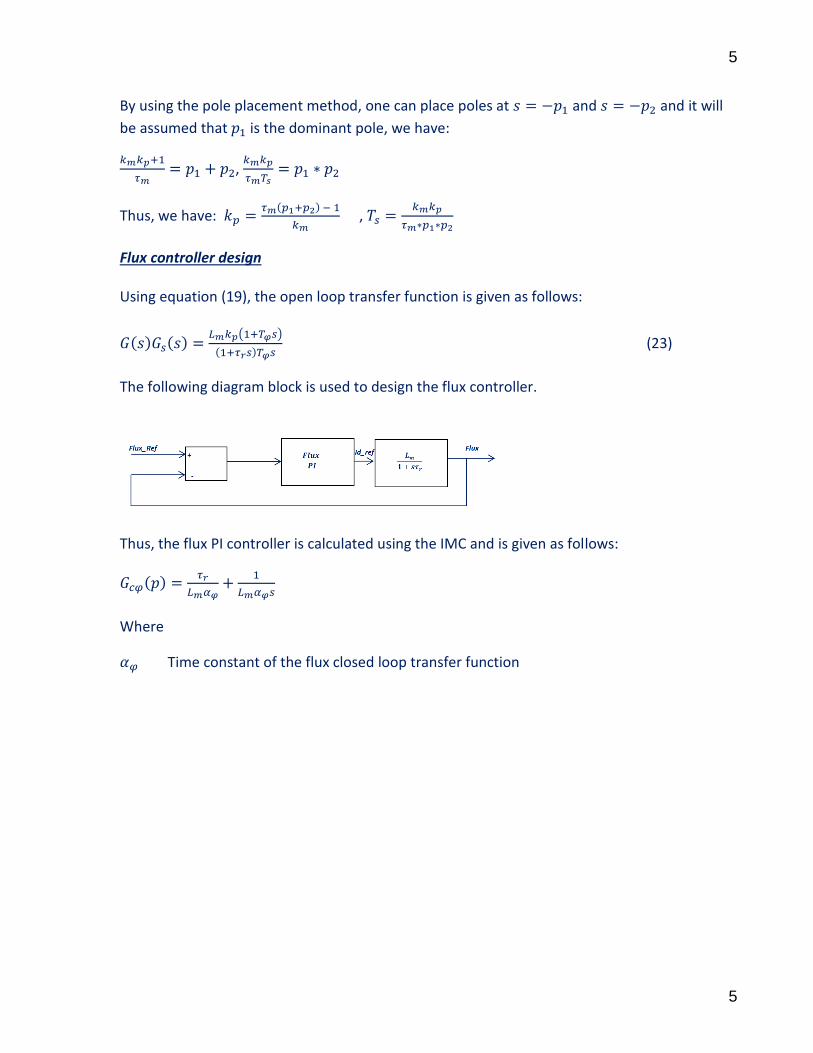
Flux controller design Using equation (19), the open loop transfer function is given as follows:
( )
(23)
The following diagram block is used to design the flux controller.
Thus, the flux PI controller is calculated using the IMC and is given as follows:
Where
Time constant of the flux closed loop transfer function

6
6
The diagram block control of Current-Sourced Inverter
5. Voltage-Sourced Inverter
The inverter is controlled by a carrier-based PWM technique. Thus, current, torque, flux and speed controllers will be designed. From (9)-(10), we have:
(24)
(25)
So, (24)-(25) into (6)-(7), we have:
(26)
(27)
With
7
7
Since and substituting equations (24)-(25) into (4)-(5) in synchronous reference
frame, we have:
(
) (28)
(
) (29)
Using (26)-(27) and the motor equations (1)-(2) in synchronous reference frame, we have:
(30)
(31)
Using (28)-(29) into (30)-(31), we have:
(
)
(
)
We know that , the above equations become:
(
)
(
)
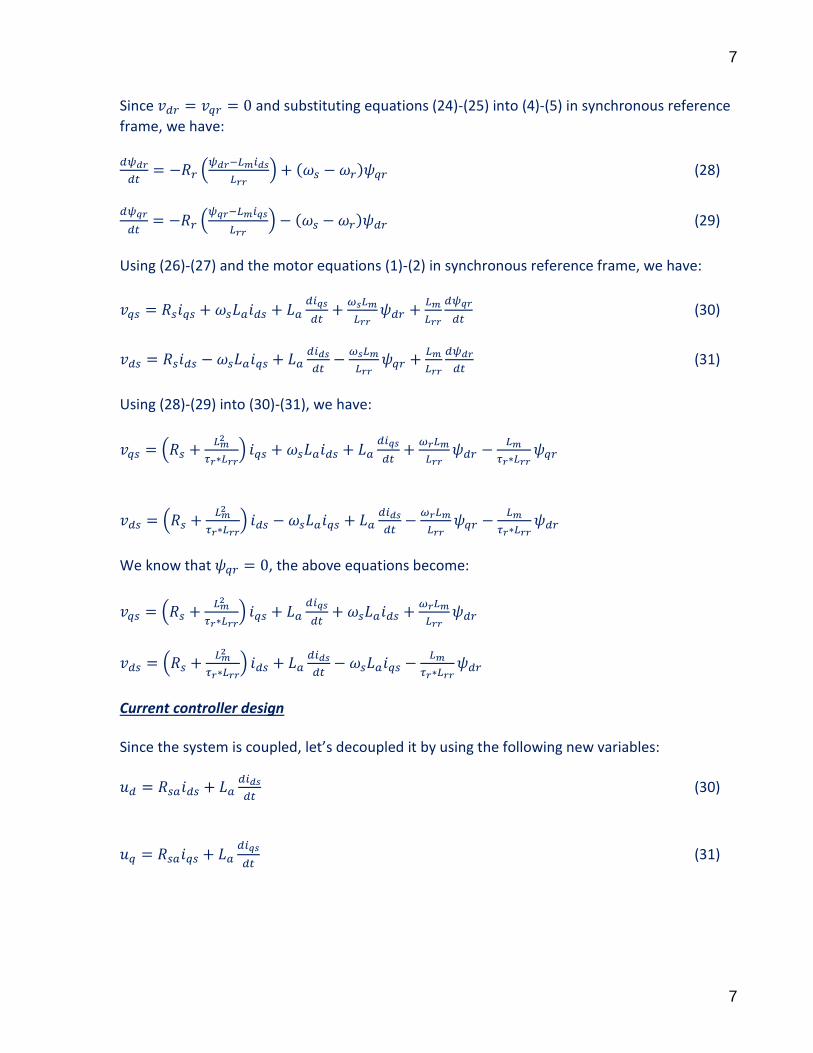
Current controller design Since the system is coupled, let’s decoupled it by using the following new variables:
(30)
(31)
8
8
Where
(
)
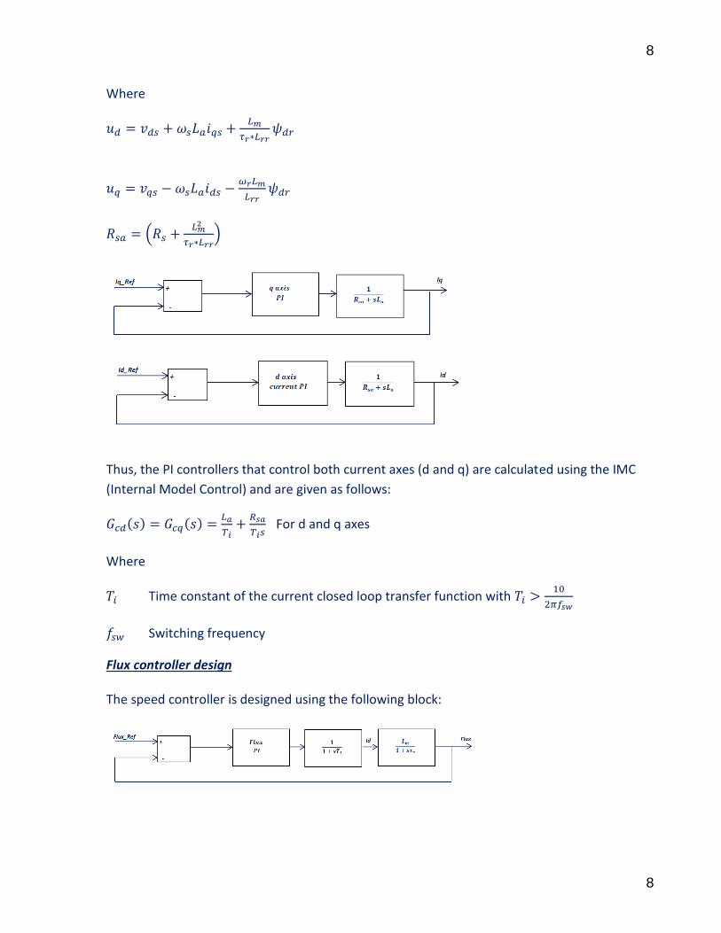
Thus, the PI controllers that control both current axes (d and q) are calculated using the IMC
(Internal Model Control) and are given as follows:
For d and q axes
Where
Time constant of the current closed loop transfer function with
Switching frequency
Flux controller design The speed controller is designed using the following block:
9
9
The open loop transfer function is given as follows:
( )
If , the open loop transfer function as follows:
( )
Thus, the flux PI controller is calculated using the IMC and is given as follows:
Where
Time constant of the flux closed loop transfer function
Suggestion: Select
A complete flux controller is designed by using the symmetrical optimum criterion. Thus, we
have:
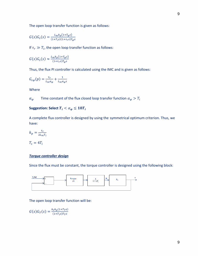
Torque controller design Since the flux must be constant, the torque controller is designed using the following block:
The open loop transfer function will be:
10
10
Where
(
)
Thus, the PI torque controller is calculated using the IMC and is given as follows:
Where Time constant of the torque closed loop transfer function
Suggestion: Select
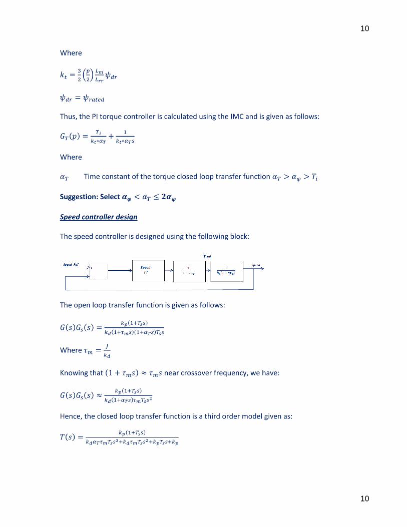
Speed controller design The speed controller is designed using the following block:
The open loop transfer function is given as follows:
Where
Knowing that near crossover frequency, we have:
Hence, the closed loop transfer function is a third order model given as:

11
11
Applying the symmetrical optimum criterion, we have:
( ) ( )
( )
Hence, we have:
,
The diagram block control of Voltage-Sourced Inverter
Note that for CHB (Cascaded H Bridge) m-Level, the modulation index is calculated as follows:
(
)
12
12
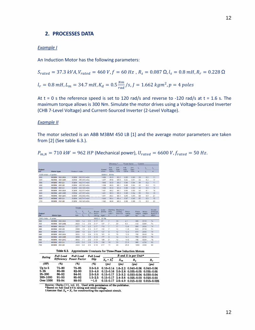
2. PROCESSES DATA
Example I An Induction Motor has the following parameters: ,
,
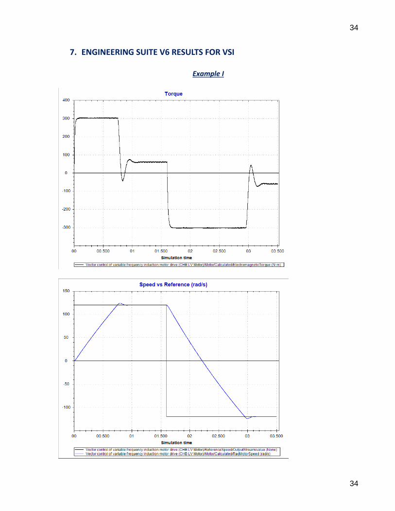
At t = 0 s the reference speed is set to 120 rad/s and reverse to -120 rad/s at t = 1.6 s. The maximum torque allows is 300 Nm. Simulate the motor drives using a Voltage-Sourced Inverter (CHB 7-Level Voltage) and Current-Sourced Inverter (2-Level Voltage).
Example II The motor selected is an ABB M3BM 450 LB [1] and the average motor parameters are taken from [2] (See table 6.3.). (Mechanical power), .
13
13
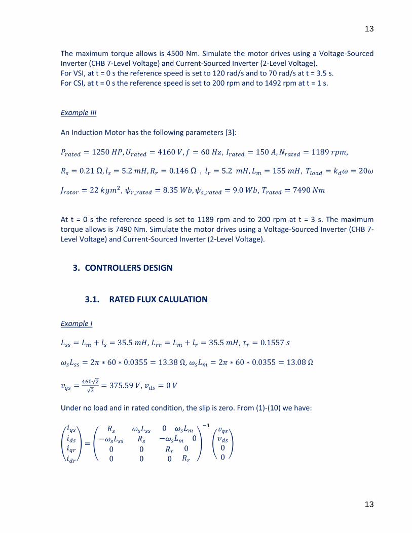
The maximum torque allows is 4500 Nm. Simulate the motor drives using a Voltage-Sourced Inverter (CHB 7-Level Voltage) and Current-Sourced Inverter (2-Level Voltage). For VSI, at t = 0 s the reference speed is set to 120 rad/s and to 70 rad/s at t = 3.5 s. For CSI, at t = 0 s the reference speed is set to 200 rpm and to 1492 rpm at t = 1 s. Example III An Induction Motor has the following parameters [3]: ,
, , , ,
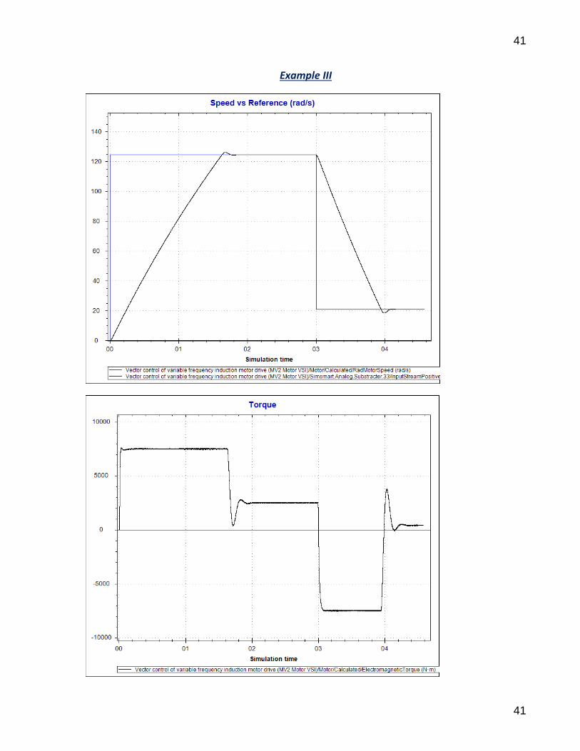
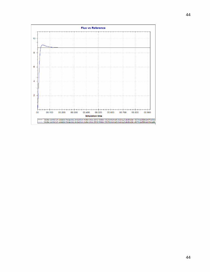
At t = 0 s the reference speed is set to 1189 rpm and to 200 rpm at t = 3 s. The maximum torque allows is 7490 Nm. Simulate the motor drives using a Voltage-Sourced Inverter (CHB 7-Level Voltage) and Current-Sourced Inverter (2-Level Voltage).
3. CONTROLLERS DESIGN
3.1. RATED FLUX CALULATION
Example I
, , ,
√
√ ,
Under no load and in rated condition, the slip is zero. From (1)-(10) we have:
(
) (
)
(
)
14
14
(
) (
)(
) (
)
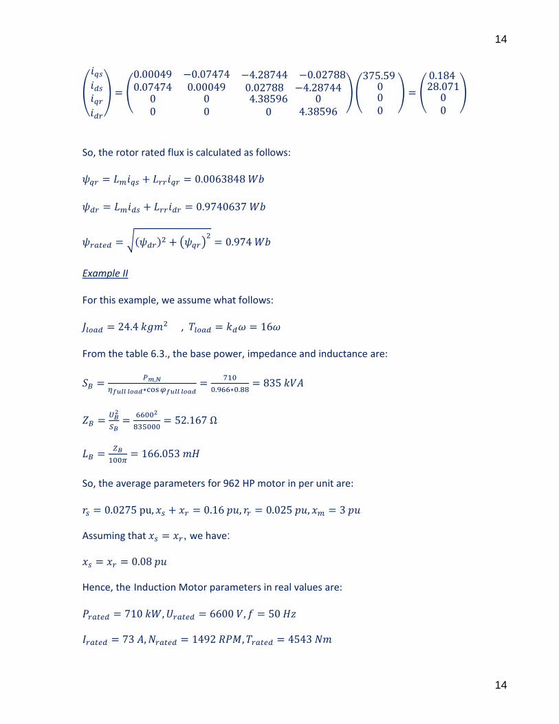
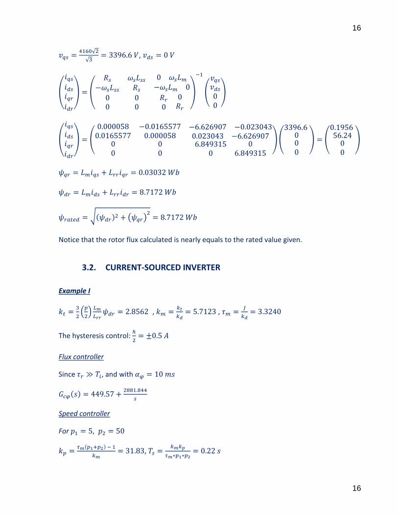
So, the rotor rated flux is calculated as follows:
√ ( )
Example II For this example, we assume what follows: , From the table 6.3., the base power, impedance and inductance are:
So, the average parameters for 962 HP motor in per unit are:
Assuming that , we have:
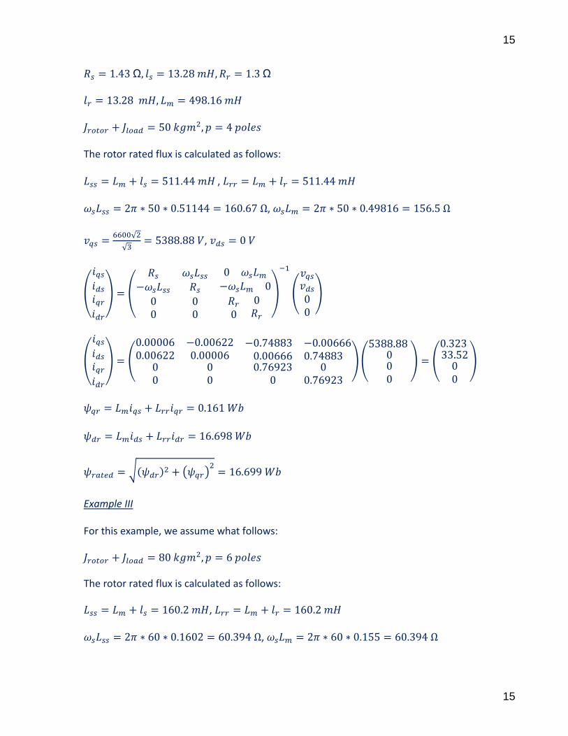
Hence, the Induction Motor parameters in real values are:
15
15
The rotor rated flux is calculated as follows: , ,
√
√ ,
(
) (
)
(
)
(
) (
)(
) (
)
√ ( )
Example III For this example, we assume what follows:
The rotor rated flux is calculated as follows:
, ,
16
16
√
√ ,
(
) (
)
(
)
(
) (
)(
) (
)
√ ( )
Notice that the rotor flux calculated is nearly equals to the rated value given.
3.2. CURRENT-SOURCED INVERTER
Example I
(
)
,
,
The hysteresis control:
Flux controller
Since , and with
Speed controller
For
,
17
17
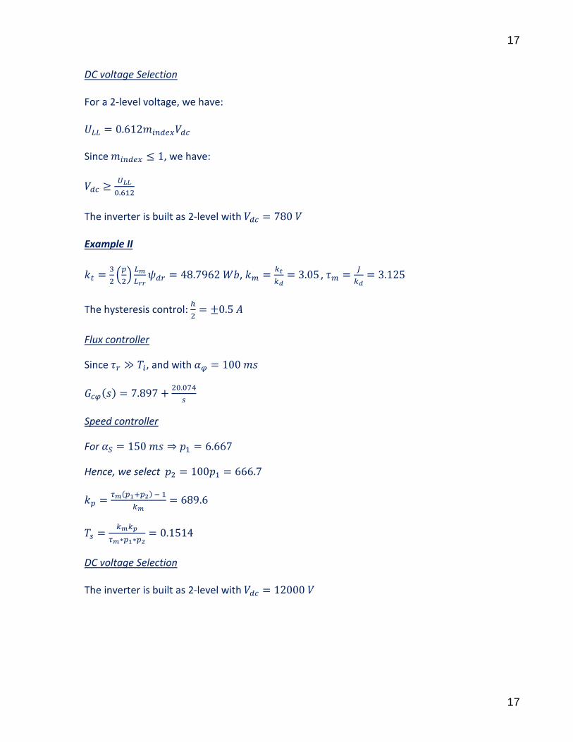
DC voltage Selection For a 2-level voltage, we have: Since , we have:
The inverter is built as 2-level with Example II
(
)
,
,
The hysteresis control:
Flux controller
Since , and with
Speed controller
For
Hence, we select
DC voltage Selection The inverter is built as 2-level with

18
18
Example III
(
)
,
,
The hysteresis control:
Flux controller
Since , and with
Speed controller
For
Hence, we select
DC voltage Selection The inverter is built as 2-level voltage with

19
19
3.3. VOLTAGE-SOURCED INVERTER
Example I
, (
)
(
)
,
Current controller
Flux controller
Since , we have:
Torque controller
Speed controller
ABC to dq measured current can be filter out with following filter
20
20
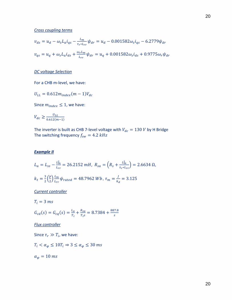
Cross coupling terms
DC voltage Selection For a CHB m-level, we have: Since , we have:
The inverter is built as CHB 7-level voltage with by H Bridge The switching frequency Example II
, (
) ,
(
)
,
Current controller
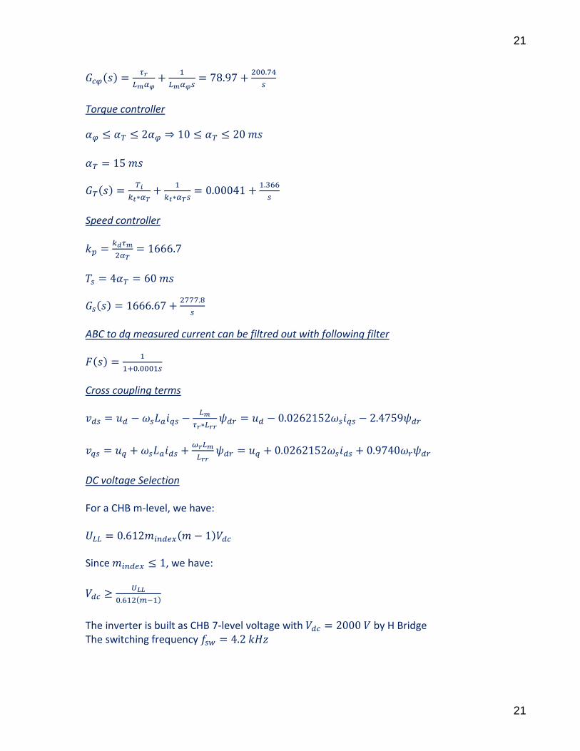
Flux controller
Since , we have:
21
21
Torque controller
Speed controller
ABC to dq measured current can be filtred out with following filter
Cross coupling terms
DC voltage Selection For a CHB m-level, we have: Since , we have:
The inverter is built as CHB 7-level voltage with by H Bridge The switching frequency
22
22
Example III
(
)
(
)
,
Current controller
Flux controller
Since , we have:
Torque controller
Speed controller
ABC to dq measured current can be filtered out with following filter
23
23
Cross coupling terms
DC voltage Selection For a CHB m-level, we have: Since , we have:
The inverter is built as CHB 7-level voltage with by H Bridge
The switching frequency
24
24
4. PROCESSES DESIGN IN ENGINEERING SUITE V6
See the end of the document
5. SIMULATION PARAMETERS
The simulation was run in time domain with sample time of

25
25
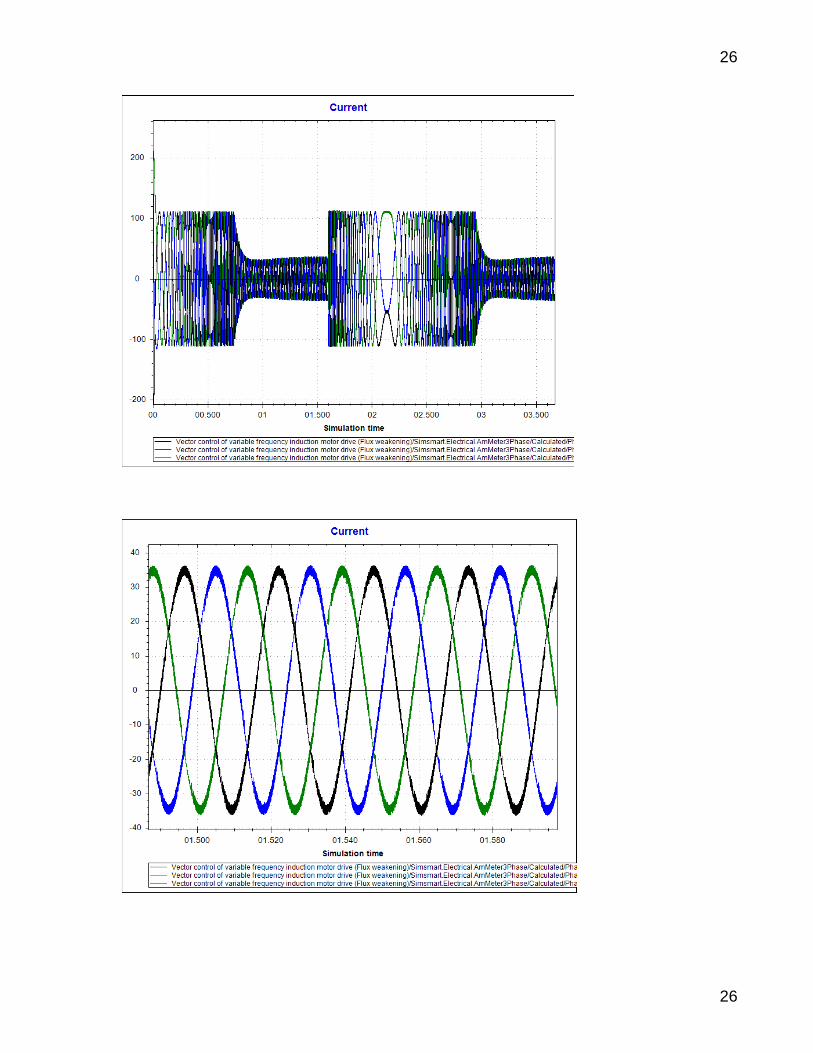
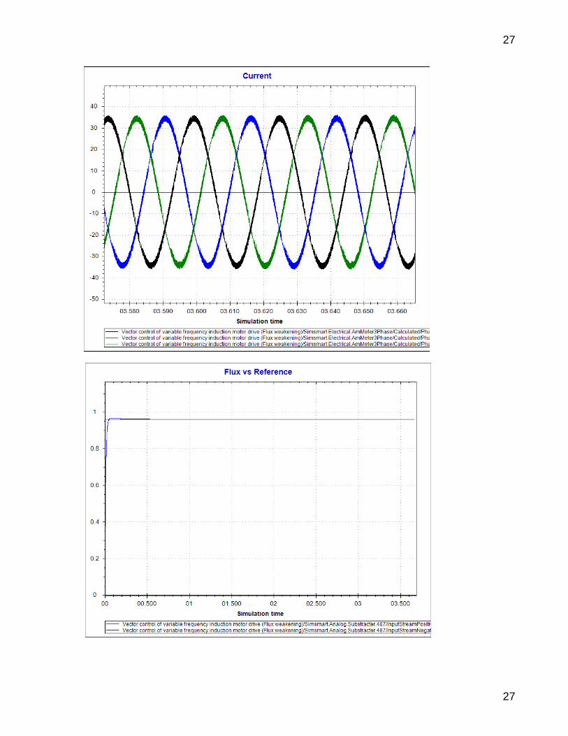
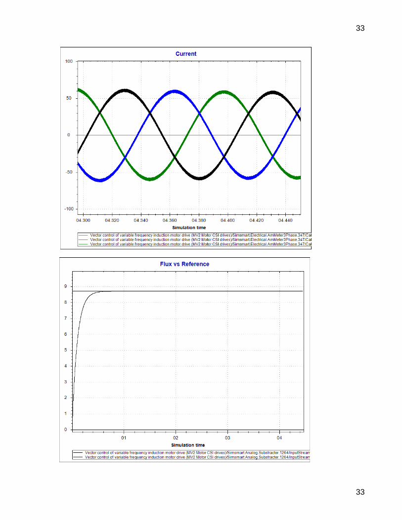
6. ENGINEERING SUITE V6 RESULTS FOR CSI
Example I
26
26
27
27

28
28
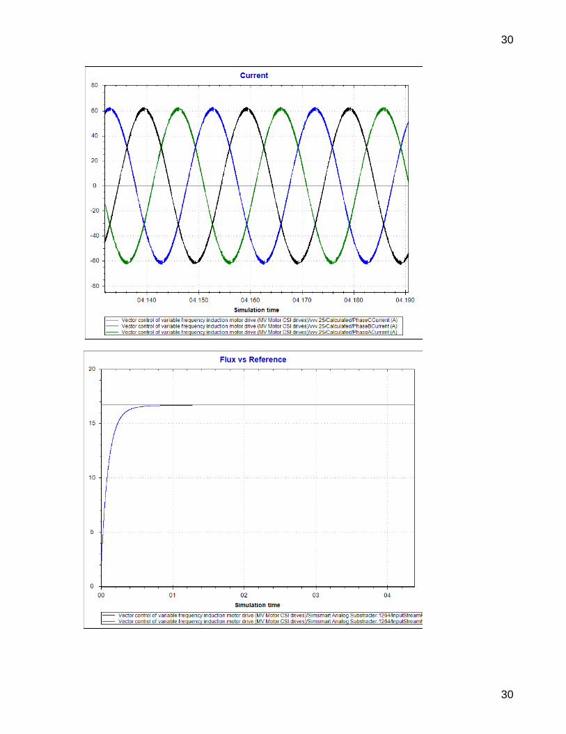
Example II
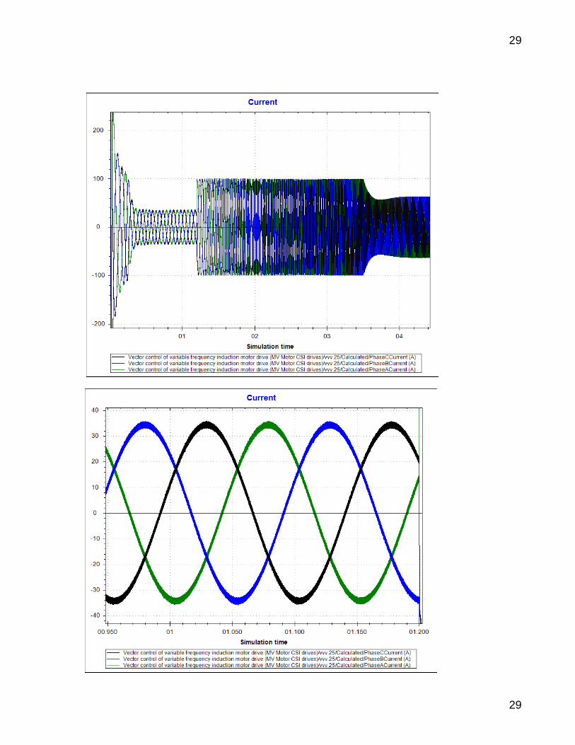
29
29
30
30

31
31
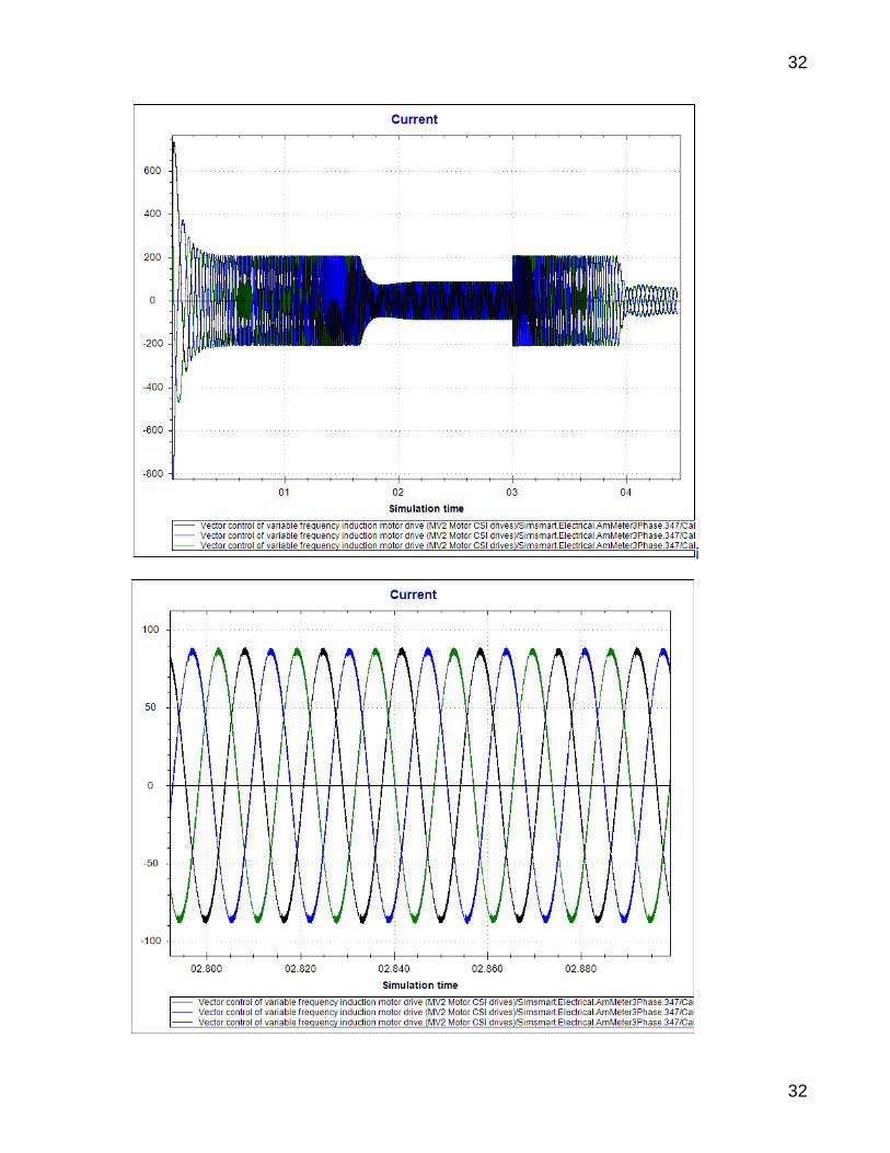
Example III
32
32
¡
33
33
34
34
7. ENGINEERING SUITE V6 RESULTS FOR VSI
Example I

35
35

36
36

37
37
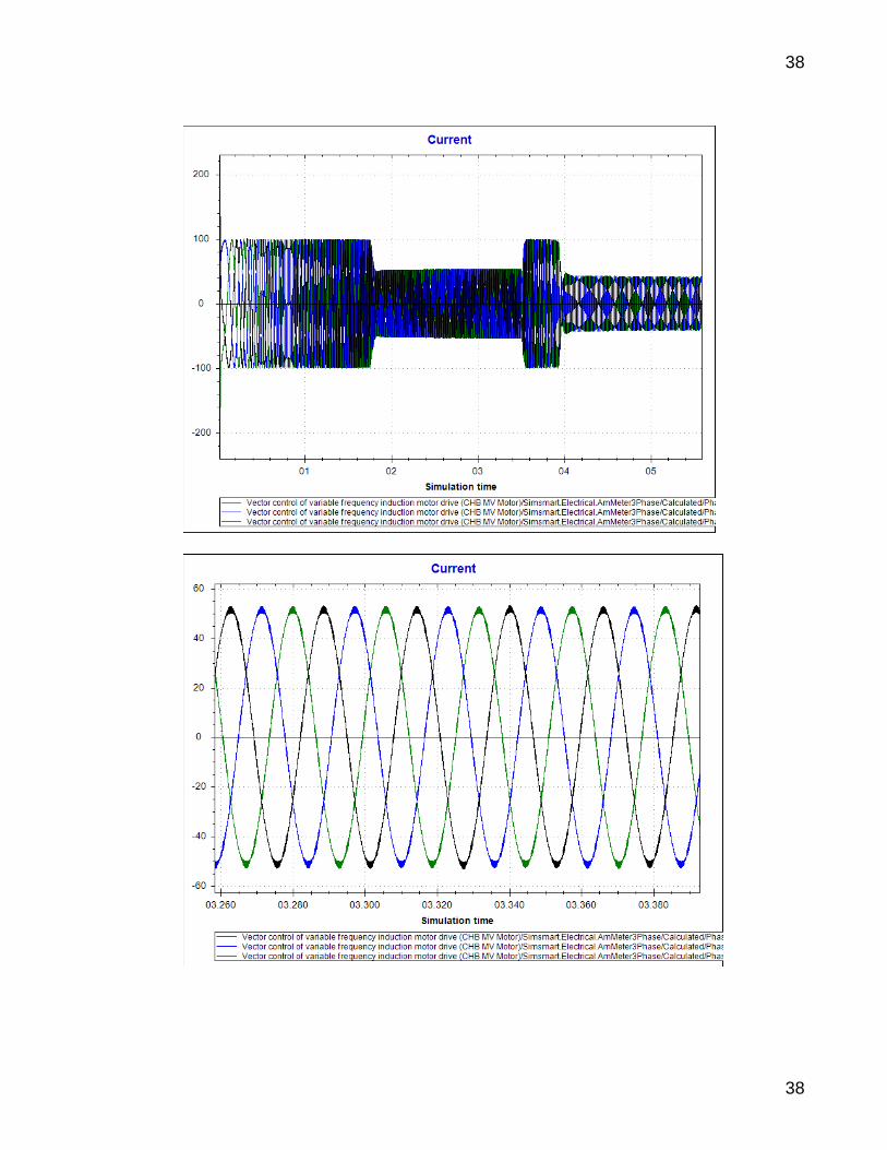
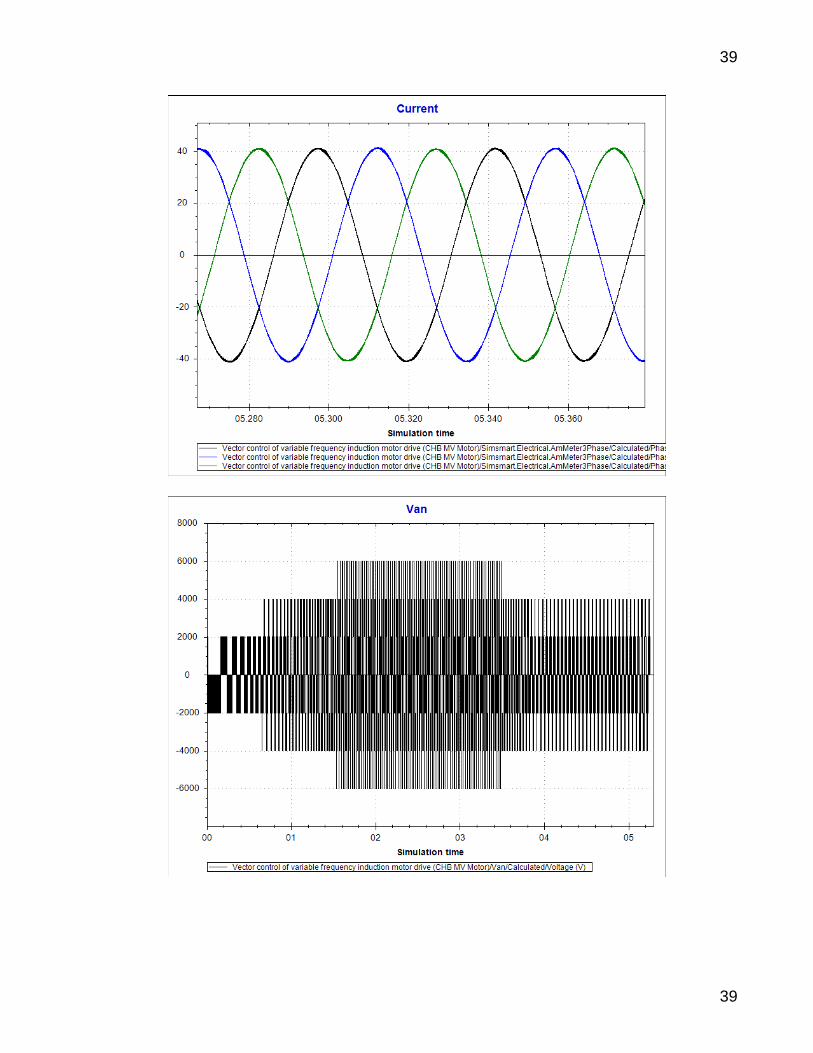
Example II
38
38
39
39

40
40
41
41
Example III

42
42

43
43
44
44
45
45
Conclusion
This document shows:
How to design controllers for Induction Motor drives,
How to select the appropriate DC voltage level. NB: All these test cases where simulated also using others well known software.
NB
In this document:
VSI (Voltage-Sourced Inverter) is simply means Voltages Control Inverter (VCI),
CSI (Current-Sourced Inverter) is simply means Currents Control Inverter (VCI).
8. REFERENCE BOOKS
1. ABB High Voltage Induction Motors.
Technical Catalogue. HV Induction Motors IEC catalogue EN 12-2007
2. Analysis of Faulted Power Systems. Paul M. Anderson
3. High-Power Converters and AC Drives. Bin Wu

3
3
M
K
Iqs_ref
ITL
Δ
Speed controller
ITL
ITL
ITL
d
0
a
Φ
b
cq
Ids_ref
sbb
saasG
10
10
)(
Iabc to dq
Flux calculation
K ∫
K
∑
÷
Δ
Δ
C ∑
3
A
IaΦ
IaIbΦ
IbIcΦ
Ic
K
Theta calculation
Speed reference
∑
K ∫
Δ
Fluxdr_ref
Speed Measured
sbb
saasG
10
10
)(
∑
∑
K
K
X
X
a
b
c
d
Φ
q
0
C
÷
÷
÷
Vdq to abc
Vabc / (3 Vdc)
C
X
K
Δ sbb
saasG
10
10
)(
sbb
saasG
10
10
)(
K
X
K
sbb
saasG
10
10
)(
Flux controller
Ids
d axis current
controller
q axis current
controller
Torque controller
Iqs
-Lm*Flux_dr /(Tr*Lrr)
-Ws*La*Iqs
Wr*Lm*Flux_dr /Lrr
Ws*La*Ids
Torque_ref
Torque limiter
sbb
saasG
10
10
)(
sbb
saasG
10
10
)(
C
CHB 7-LEVEL VOLTAGE DRIVES INDUCTION MOTOR
≥
≥
31a
b
c
≥
≥
≥
≥
≥
≥
≥
≥
≥
≥
≥
≥
≥
≥
≥
≥
Carrier phase 0 deg
Carrier phase 180 deg
Carrier phase 60 deg
Carrier phase 240 deg
Carrier phase 120 deg
Carrier phase 300 deg
VΦV C
T
V Van Voltage
VΦV C
T
V
VΦV C
T
V Vcn VoltageVbn Voltage
Ungrounded
Motor

31a
b
c
3
3
M
K
ITL
Δ
Speed controller
d
0
a
Φ
b
cq
sbb
saasG
10
10
)(
Iabc to dq
Flux calculation
K∫
K
∑
÷C ∑
K
Theta calculation
Speed reference
∑
K ∫
Fluxdr_ref
C
Speed Measured
3
A
IaΦ
IaIbΦ
IbIcΦ
Ic
Flux controller
Torque_ref
Torque limiter
∑
÷
Iqs*
a
b
c
d
Φ
q
0
C
Ids*
Δ
Δ
Δ A/D
A/D
A/D
Idq to abc
calculation
sbb
saasG
10
10
)(Δ
ITL
ITL
ITL
ITL
ITL
ITL
C
K
K
2-LEVEL VOLTAGE DRIVES INDUCTION MOTOR
Hysteresis
control
Iabc
Ungrounded
Motor