Embed Size (px)
Citation preview
GA–A25661
TUNGSTEN SPUTTER COATING DEVELOPMENT TO PRODUCE HIGH Z SHELLS
by D.G. CZECHOWICZ, J.A. DORMAN, J.C. GERONIMO, and C.J. CHEN
JANUARY 2007
DISCLAIMER
This report was prepared as an account of work sponsored by an agency of the United States Government. Neither the United States Government nor any agency thereof, nor any of their employees, makes any warranty, express or implied, or assumes any legal liability or responsibility for the accuracy, completeness, or usefulness of any information, apparatus, product, or process disclosed, or represents that its use would not infringe privately owned rights. Reference herein to any specific commercial product, process, or service by trade name, trademark, manufacturer, or otherwise, does not necessarily constitute or imply its endorsement, recommendation, or favoring by the United States Government or any agency thereof. The views and opinions of authors expressed herein do not necessarily state or reflect those of the United States Government or any agency thereof.
GA–A25661
TUNGSTEN SPUTTER COATING DEVELOPMENT TO PRODUCE HIGH Z SHELLS
by D.G. CZECHOWICZ, J.A. DORMAN,† J.C. GERONIMO,‡ and C.J. CHEN*
This is a preprint of a paper presented at the 17th Target Fabrication Specialist Meeting, San Diego, California on October 1-5, 2006 and to be published in Fusion Science and Technology.
†University of California-Los Angeles, Los Angeles, California. ‡Cambria Environmental Technology, Emeryville, California.
*University of California-San Diego, La Jolla, California.
Work supported by the U.S. Department of Energy
under DE-AC03-01SF22260, DE-AC52-06NA27279, UCSD and UCLA
GENERAL ATOMICS PROJECT 30272 JANUARY 2007
TUNGSTEN SPUTTER COATING DEVELOPMENT TO PRODUCE HIGH Z SHELLS D.G. Czechowicz, et al.
GENERAL ATOMICS REPORT GA-A25661 1
TUNGSTEN SPUTTER COATING DEVELOPMENT TO PRODUCE HIGH Z SHELLS
D.G. Czechowicz,1 J.A. Dorman,2 J.C. Geronimo,3 and C.J. Chen4
1General Atomics, P.O. Box 85608, San Diego, California 92186-5608 2University of California, Los Angeles, 405 Hilgard Avenue, Los Angeles, California 90095
3Cambria Environmental Technology, 5900 Hollis Street, Emeryville, California 94608 4University of California, San Diego, 9500 Gilman Drive, La Jolla, California 92093
We developed a production tungsten sputter coating
process to uniformly deposit tungsten on 840 μm outer
diameter GDP shells using a bounce coating technique.
We were able to control the tungsten-coating rate and
therefore coating thickness based on gravimetric analysis.
At the end of our work we could routinely produce
uniform 0.5 μm tungsten coatings on GDP shells with a !
wall <0.04 μm. Techniques were developed and applied
to measure coating uniformity based on x-radiography
and x-ray fluorescence data. Typical surface roughness
values for bounce coated shells having a 0.5 μm tungsten
coating were 40 to 50 nm RMS. Stationary GDP shells
were coated with 0.5 μm tungsten and found to have
surface roughness approaching 10 nm RMS, which was
similar to the roughness of the underlying GDP mandrel
surface. This result indicates that coating processes with
less agitation such as tap or roll coating may produce
much smoother tungsten coatings.
I. INTRODUCTION
There are accounts of the sputter deposition of
tungsten on various substrates for electronic and wear
resistant applications in the literature.1�3 Deposition of
uniform high Z coatings on shells has been investigated
using magnetron sputtering previously by others for
applications in Inertial Confinement Fusion.4,5 Over the
last few years our group has investigated the sputter
deposition of the high Z metals gold and palladium on
shells for Inertial Fusion Energy applications.6 More
recently workers in our laboratory had carried out a
limited study to sputter coat tungsten on glass shells to see
if such shells could be permeation filled with D2.7 In this
paper we report the development of tungsten coatings to
produce high Z shells focusing on production and
measurement of uniform tungsten wall thickness shells.
II. EXPERIMENTAL
During our current tungsten coating development
studies we used magnetron sputter coating of pure
tungsten initially on flat and then spherical substrates.
Preliminary coating runs were on a combination of glass
cover slips, sapphire spheres, PAMS shells, and GDP
shells to understand and optimize the coating process. We
arrived at an optimum coating distance between the
tungsten sputter target and our substrates of 10 cm.
During coating development we were able to determine
coating rates for flats, stationary shells, and bounced
shells. We used a piezoelectric bounce pan system in
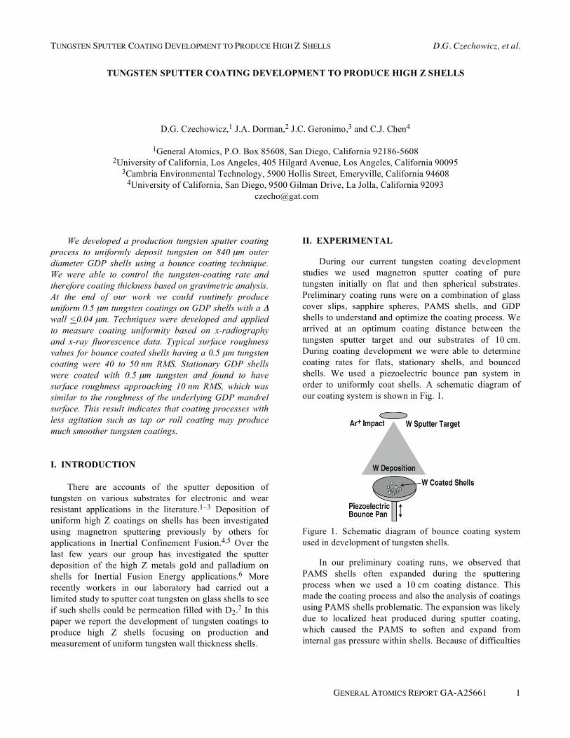
order to uniformly coat shells. A schematic diagram of
our coating system is shown in Fig. 1.
Figure 1. Schematic diagram of bounce coating system
used in development of tungsten shells.
In our preliminary coating runs, we observed that
PAMS shells often expanded during the sputtering
process when we used a 10 cm coating distance. This
made the coating process and also the analysis of coatings
using PAMS shells problematic. The expansion was likely
due to localized heat produced during sputter coating,
which caused the PAMS to soften and expand from
internal gas pressure within shells. Because of difficulties
D.G. Czechowicz, et al. TUNGSTEN SPUTTER COATING DEVELOPMENT TO PRODUCE HIGH Z SHELLS
2 GENERAL ATOMICS REPORT GA-A25661
in tungsten coating of PAMS mandrels, all later
development focused on tungsten coating of GDP
mandrels which did not change size during sputter
coating. Tungsten coated GDP shells provided us
reproducible and unambiguous results for coatings.
The GDP shells used during tungsten coating
development had a nominal outer diameter of 840 μm and
a wall thickness of 14 μm. We typically bounce coated
batches of 5 GDP shells at a time. In all we carried out
eleven production runs of 5 shell batches. The last coating
run carried out used a batch of 10 GDP mandrels, as a
curiosity, to see if we could observe any relationship
between batch size and coating surface finish. Average
thickness for the tungsten coatings was determined
gravimetrically by weighing shells before and after
tungsten deposition. Shell diameters were measured by
interferometry and shell weights were measured using a
Cahn microbalance.
Coating rates for shells were determined from the
average tungsten coating thickness. In addition, some
shells were examined by SEM to verify coating thickness.
A typical tungsten coating rate for bounced shells was
~0.40 μm/h once our coating process was under control.
Surface roughness was measured for both stationary
coated shells and bounce coated shells by using a Veeco
Instruments WYKO Surface Profiler. A new quantitative
radiography method was applied to tungsten bounce
coated shells to determine tungsten wall uniformity.8 In
addition, an x-ray fluorescence analysis method was
carried out on one of the shells analyzed by quantitative
radiography to verify wall uniformity. These two methods
will be described along with results later in this paper.
III. RESULTS
III.A. SEM Examination
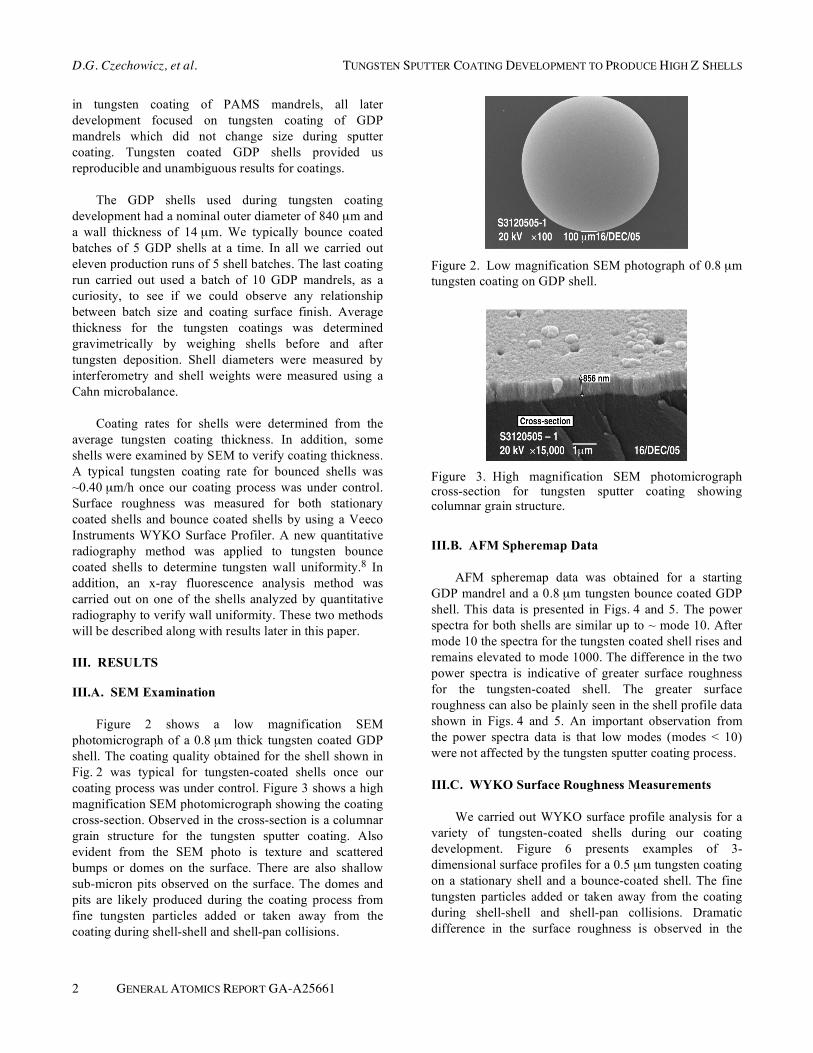
Figure 2 shows a low magnification SEM
photomicrograph of a 0.8 μm thick tungsten coated GDP
shell. The coating quality obtained for the shell shown in
Fig. 2 was typical for tungsten-coated shells once our
coating process was under control. Figure 3 shows a high
magnification SEM photomicrograph showing the coating
cross-section. Observed in the cross-section is a columnar
grain structure for the tungsten sputter coating. Also
evident from the SEM photo is texture and scattered
bumps or domes on the surface. There are also shallow
sub-micron pits observed on the surface. The domes and
pits are likely produced during the coating process from
fine tungsten particles added or taken away from the
coating during shell-shell and shell-pan collisions.
Figure 2. Low magnification SEM photograph of 0.8 μm
tungsten coating on GDP shell.
Figure 3. High magnification SEM photomicrograph cross-section for tungsten sputter coating showing columnar grain structure.
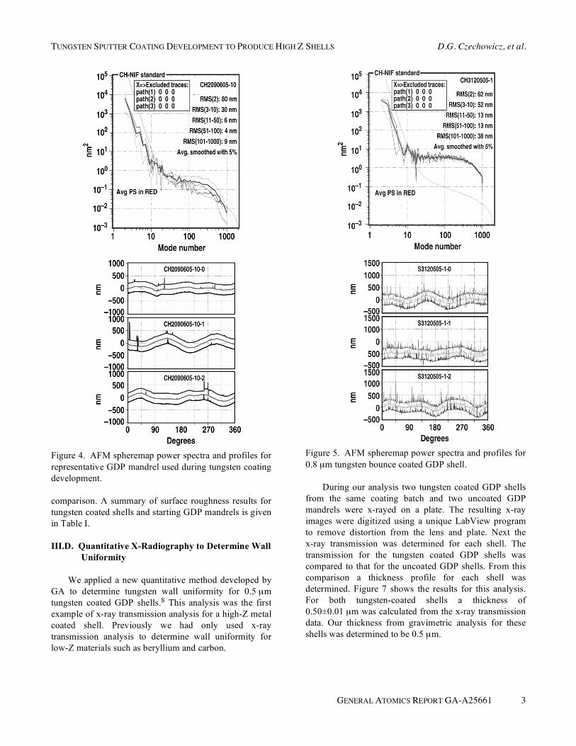
III.B. AFM Spheremap Data
AFM spheremap data was obtained for a starting
GDP mandrel and a 0.8 μm tungsten bounce coated GDP
shell. This data is presented in Figs. 4 and 5. The power
spectra for both shells are similar up to ~ mode 10. After
mode 10 the spectra for the tungsten coated shell rises and
remains elevated to mode 1000. The difference in the two
power spectra is indicative of greater surface roughness
for the tungsten-coated shell. The greater surface
roughness can also be plainly seen in the shell profile data
shown in Figs. 4 and 5. An important observation from
the power spectra data is that low modes (modes < 10)
were not affected by the tungsten sputter coating process.
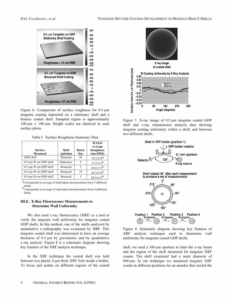
III.C. WYKO Surface Roughness Measurements
We carried out WYKO surface profile analysis for a
variety of tungsten-coated shells during our coating
development. Figure 6 presents examples of 3-
dimensional surface profiles for a 0.5 μm tungsten coating
on a stationary shell and a bounce-coated shell. The fine
tungsten particles added or taken away from the coating
during shell-shell and shell-pan collisions. Dramatic
difference in the surface roughness is observed in the
TUNGSTEN SPUTTER COATING DEVELOPMENT TO PRODUCE HIGH Z SHELLS D.G. Czechowicz, et al.
GENERAL ATOMICS REPORT GA-A25661 3
Figure 4. AFM spheremap power spectra and profiles for
representative GDP mandrel used during tungsten coating
development.
comparison. A summary of surface roughness results for
tungsten coated shells and starting GDP mandrels is given
in Table I.
III.D. Quantitative X-Radiography to Determine Wall
Uniformity
We applied a new quantitative method developed by
GA to determine tungsten wall uniformity for 0.5 μm
tungsten coated GDP shells.8 This analysis was the first
example of x-ray transmission analysis for a high-Z metal
coated shell. Previously we had only used x-ray
transmission analysis to determine wall uniformity for
low-Z materials such as beryllium and carbon.
Figure 5. AFM spheremap power spectra and profiles for
0.8 μm tungsten bounce coated GDP shell.
During our analysis two tungsten coated GDP shells
from the same coating batch and two uncoated GDP
mandrels were x-rayed on a plate. The resulting x-ray
images were digitized using a unique LabView program
to remove distortion from the lens and plate. Next the
x-ray transmission was determined for each shell. The
transmission for the tungsten coated GDP shells was
compared to that for the uncoated GDP shells. From this
comparison a thickness profile for each shell was
determined. Figure 7 shows the results for this analysis.
For both tungsten-coated shells a thickness of
0.50±0.01 μm was calculated from the x-ray transmission
data. Our thickness from gravimetric analysis for these
shells was determined to be 0.5 μm.
D.G. Czechowicz, et al. TUNGSTEN SPUTTER COATING DEVELOPMENT TO PRODUCE HIGH Z SHELLS
4 GENERAL ATOMICS REPORT GA-A25661
Figure 6. Comparison of surface roughness for 0.5 μm
tungsten coating deposited on a stationary shell and a
bounce coated shell. Sampled region is approximately
100 μm ! 100 μm. Height scales are identical in each
surface photo.
Table I. Surface Roughness Summary Data
Surface
Measured
Shell
Agitation
Batch
Size
WYKO
Average
Roughness
(nm RMS) GDP shell Bounced 30 10.3±2.8a 0.5 μm W on GDP shell Stationary 5 11.2±3.2a 0.5 μm W on GDP shell Bounced 5 45.0±7.3b 0.5 μm W on GDP shell Bounced 10 66.5±9.0a 0.8 μm W on GDP shell Bounced 5 84.5±4.5b
aCorresponds to average of individual measurements from 5 different shells.
bCorresponds to average of individual measurements from 4 different shells.
III.E. X-Ray Fluorescence Measurements to
Determine Wall Uniformity
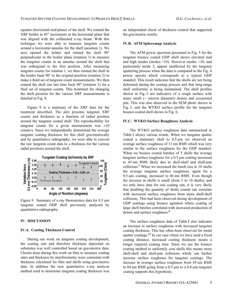
We also used x-ray fluorescence (XRF) as a tool to verify the tungsten wall uniformity for tungsten coated GDP shells. In this method, one of the shells analyzed by quantitative x-radiography was examined by XRF. This tungsten coated shell was determined to have an average thickness of 0.5 μm by gravimetric and by quantitative x-ray analysis. Figure 8 is a schematic diagram showing key features of the XRF analysis technique.
In the XRF technique the coated shell was held
between two plastic 4 μm thick XRF foils inside a holder.
To focus and isolate on different regions of the coated
Figure 7. X-ray image of 0.5 μm tungsten coated GDP
shell and x-ray transmission analysis data showing
tungsten coating uniformity within a shell, and between
two different shells.
Figure 8. Schematic diagram showing key features of
XRF analysis technique used to determine wall
uniformity for tungsten coated GDP shells.
shell, we used a 100 μm aperture to limit the x-ray beam
and the region of the shell measured for tungsten XRF
counts. The shell examined had a outer diameter of
840 μm. In our technique we measured tungsten XRF
counts in different positions for an annulus that circled the
TUNGSTEN SPUTTER COATING DEVELOPMENT TO PRODUCE HIGH Z SHELLS D.G. Czechowicz, et al.
GENERAL ATOMICS REPORT GA-A25661 5
equator (horizontal mid-plane) of the shell. We rotated the
XRF holder in 45° increments in the horizontal plane that
was aligned with the collimated x-ray beam. With this
technique we were able to measure tungsten counts
around a horizontal annulus for the shell (position 1). We
next opened the holder and rotated the shell 90°
perpendicular to the holder plane (rotation 1) to measure
the tungsten counts in an annulus around the shell that
was orthogonal to the first position. After measuring
tungsten counts for rotation 1, we then rotated the shell in
the holder back 90° to the original position (rotation 2) to
make a third set of tungsten count measurements. We then
rotated the shell one last time back 90° (rotation 3) for a
final set of tungsten counts. This treatment for changing
the shell position for the various XRF measurements is
detailed in Fig. 8.
Figure 9 is a summary of the XRF data for the
treatment described. The plot presents tungsten XRF
counts and thickness as a function of radial position
around the tungsten coated shell. The reproducibility for
tungsten counts for a given measurement was ±10
counts/s. Since we independently determined the average
tungsten coating thickness for this shell gravimetrically
and by quantitative radiography, we were able to convert
the raw tungsten count data to a thickness for the various
radial positions around the shell.
Figure 9. Summary of x-ray fluorescence data for 0.5 μm
tungsten coated GDP shell previously analyzed by
quantitative radiography.
IV. DISCUSSION
IV.A. Coating Thickness Control
During our work on tungsten coating development,
the coating rate and therefore thickness deposited on
substrates was well controlled based on gravimetric data.
Checks done during this work on flats to measure coating
rates and thickness by interferometry were consistent with
thickness calculated for flats and shells using gravimetric
data. In addition the new quantitative x-ray analysis
method used to determine tungsten coating thickness was
an independent check of thickness control that supported
the gravimetric results.
IV.B. AFM Spheremap Analysis
The AFM power spectrum presented in Fig. 5 for the
tungsten bounce coated GDP shell shows elevated mid
and high modes (modes >10). However modes <10, and
particularly mode 2, appear unaffected by the tungsten
sputtering process when the data is compared to the Fig. 4
power spectra which corresponds to a typical GDP
mandrel. This result indicates that the shells are not being
deformed during the coating process and that long-range
shell uniformity is being maintained. The shell profiles
shown in Fig. 5 are indicative of a rough surface with
many small (~ micron diameter) domes and occasional
pits. This was also observed in the SEM photo shown in
Fig. 3, and the WYKO surface profile for the tungsten
bounce coated shell shown in Fig. 6.
IV.C. WYKO Surface Roughness Analysis
The WYKO surface roughness data summarized in
Table I shows various trends. When we tungsten sputter
coated a stationary shell to 0.5 μm we observed an
average surface roughness of 11 nm RMS which was very
similar to the surface roughness for the GDP mandrel.
When we bounce coated batches of 5 shells the average
tungsten surface roughness for a 0.5 μm coating increased
to 45 nm RMS likely due to shell-shell and shell-pan
collisions.9 When we increased the batch size to 10 shells
the average tungsten surface roughness, again for a
0.5 μm coating, increased to 66 nm RMS. Even though
the increase in shells is small (from 5 to 10 shells), and
we only have data for one coating run, it is very likely
that doubling the quantity of shells coated can correlate
with increased surface roughness from more shell-shell
collisions. This had been observed during development of
GDP coatings using bounce agitation where coating of
large shell batches correlated with increased production of
domes and surface roughness.9
The surface roughness data of Table I also indicates
an increase in surface roughness with increased tungsten
coating thickness. This has often been observed for metal
sputter coatings.10 In our case where we have used a fixed
coating distance, increased coating thickness means a
longer required coating time. Since we use the bounce
coating method to uniformly coat shells this means more
shell-shell and shell-pan collisions which can further
increase surface roughness for tungsten coatings. The
increase in average surface roughness from 45 nm RMS
to 84 nm RMS going from a 0.5 μm to a 0.8 μm tungsten
coating supports this hypothesis.
D.G. Czechowicz, et al. TUNGSTEN SPUTTER COATING DEVELOPMENT TO PRODUCE HIGH Z SHELLS
6 GENERAL ATOMICS REPORT GA-A25661
There is one important observation to make for the
roughness data obtained for the stationary coated shell.
After coating, WYKO surface analysis showed the sta-
tionary coated surface to have roughness that remained at
approximately 10 nm RMS. Since the sampling of the
stationary shell was at the north pole this region is similar
to a flat substrate and would yield the smoothest surface.
Sampling the stationary shell near the equator would
likely yield a rougher surface. This is an important result
which shows that if one could coat shells uniformly with
less agitation, the surface can be made very smooth with
the measured roughness approaching that of the underly-
ing substrate.
There are various ways to agitate shells during sput-
ter coating to try to obtain uniform coatings; bounce
coating, tap coating, and roll coating. In the work we pre-
sent here, we used bounce coating, as this technique is the
production method used to fabricate uniform coatings on
the majority of small (<1 mm diameter) spherical ICF
targets. However for sputter coating, the surface rough-
ness may increase undesirably from the bouncing process.
Surface roughness can be decreased by tap or roll
coating of shells.9 Past experience for coating of GDP
shells has shown that agitation by rolling or tapping can
produce shell surfaces with less features when compared
to agitation by bouncing for the same number of shells
coated to the same thickness.9 This data indicates that
much improved surface roughness can be obtained using a
tap or roll coating process. Therefore improved surfaces
for tungsten sputter coated shells may be obtained in the
future using tapping or rolling for shell agitation. The
coating uniformity for coated shells would need to be
monitored during trial of these other agitation methods,
since smooth coating surfaces and uniform walls are not
necessarily correlated.
IV.D. Tungsten Coating Uniformity
The coating uniformity of the tungsten-coated shells
was determined in two ways. The first method used was
quantitative x-radiography which determined the tungsten
wall uniformity in one view (one plane) for a shell. In
addition since we analyzed two shells from the same
batch by this method we obtained an indication of
uniformity from shell to shell. The second method used to
determine wall uniformity was by XRF measurements on
one of the shells analyzed by x-radiography. During the
XRF analysis the shell was rotated 90° after each set of
measurements which allowed shell coating uniformity for
two orthogonal planes to be determined.
Quantitative x-radiography can be a very sensitive
technique to characterize wall thickness uniformity.8
Using spectra for x-ray transmission, the difference in
transmission across 200 different radial lines for each
shell was calculated. The sensitivity of the LabView pro-
gram to read the transmission spectrum is 2.7%, meaning
that for every 0.027 change in transmission there is a
0.01 μm change in thickness. The results of measure-
ments for two different tungsten coated shells from the
same batch shown in Fig. 7 indicates that the uniformity
of the tungsten coating within the two shells was
±0.01 μm. In addition, comparison of the coating thick-
ness results from the x-ray transmission data for the two
shells showed them to have an average tungsten coating
thickness within 0.01 μm of each other. Therefore the
tungsten coatings were indicated to be uniform from shell
to shell, inferred from the two sampled bounce coated
shells. This result was consistent with gravimetric average
coating thickness data for bounce-coated shells from the
same batch.
Figure 9 is the coating thickness uniformity based on
XRF measurements for one of the tungsten-coated shells
that was analyzed by quantitative radiography. Evaluation
of the radial data in the Fig. 9 plot shows the data to be
relatively flat. This suggests that the tungsten coating on
the bounce-coated shell analyzed is fairly uniform. When
we take the average tungsten counts at each radial posi-
tion and convert these to a thickness using the average
coating thickness from gravimetric analysis, we observe
that the coating thickness around the shell is 0.49
±0.02 μm. This result and the waviness of the plotted data
as a function of radial position are both similar to the
quantitative radiography results presented in Fig. 7. These
observations are not surprising since the same shell was
analyzed by both methods. The rather good agreement
between the two independent analysis methods, quantita-
tive x-radiography and x-ray fluorescence measurements,
suggests that both methods can be used to characterize
tungsten coating uniformity.
V. SUMMARY
The first controlled production of thin wall tungsten
shells was carried out. We successfully developed a
production sputter coating process to deposit pure
tungsten uniformly on GDP shells. Problems were
encountered sputter coating tungsten on PAMS shells
because of shell expansion due to shell heating during the
coating process. The coating rate and thickness for
deposited tungsten coatings on GDP shells was well
controlled during our study based on gravimetric analysis.
TUNGSTEN SPUTTER COATING DEVELOPMENT TO PRODUCE HIGH Z SHELLS D.G. Czechowicz, et al.
GENERAL ATOMICS REPORT GA-A25661 7
New techniques were developed to complement the
gravimetric analysis of tungsten coating thickness to
determine uniformity for coatings. These new techniques
were quantitative x-radiography and x-ray fluorescence
measurements. The analysis techniques to determine wall
uniformity indicated that we could produce uniform
0.5 μm tungsten coatings on GDP shells having a ! wall
<0.04 μm using bounce coating.
The best surface roughness for a bounce-coated shell
having a 0.5 μm tungsten coating was approximately
40 nm RMS. Stationary coated shells were observed to
have much better surface roughness. Stationary GDP
shells that were coated with 0.5 μm tungsten were found
to have surface roughness approaching 10 nm RMS,
which was close to the roughness of the underlying GDP
mandrel surface. This result indicates that coating
processes with less agitation such as tap or roll coating
may produce much smoother tungsten coatings. Previous
studies during development of GDP coatings showed that
tap and roll coating can produce very smooth shell
surfaces. Future efforts for development of high quality
tungsten coatings should focus on improved agitation
methods during tungsten deposition, and investigations
into the effect of batch size and coating thickness on final
coating quality.
ACKNOWLEDGMENT
Work supported by U.S. Department of Energy under
DE-AC03-01SF22260 and DE-AC52-06NA27279. The
authors would like to acknowledge the following General
Atomics staff, J. Gibson and T. Lee for carrying out AFM
spheremap measurements, R. Luo for characterization
measurements on GDP mandrels, and T. Bernat and D.A.
Steinman for helpful discussions during analysis of
results.
REFERENCES
1. L. CHI-FUNG, P. MCDONALD, D. DRAPER, and
P. GILMAN, �Influence of Tungsten Sputtering
Target Density on Physical Vapor Deposition Thin
Film Properties: Microstructures and Textures of
Films and Coatings and Refractory Metals in
Electronic Applications,� J. Electronic Materials 34,
1468 (2005).
2. C. WANG, et al., �Deposition and Structure of
W-Cu Multilayer Coatings by Magnetron Sputtering,�
J. Phys. D 36, 2709 (2003).
3. R. H. JONES, R. W. MOSS, E. D. MCCLANAHAN,
and H. L. BUTTS, �The Sputter Deposition and
Evaluation of Tungsten and Chromium for Use in
Weapon Components,� Battelle Memorial Institute,
Northwest Labs, Technical Report ADA024109,
(1975).
4. S. F. MEYER, �Metallic Coating of Microspheres,�
J. Vac. Sci. Technol. 18, 1198 (1981).
5. E. J. HSIEH and S. F. MEYER, �Recent Advances in
Pt Coating of Microspheres by a Batch Magnetron
Sputtering Process,� J. Vac. Sci. Technol. 18, 1205
(1981).
6. E. H. STEPHENS, A. NIKROO, D. T. GOODIN, and
R. W. PETZOLDT, �Optimizing High-Z Coatings for
Inertial Fusion Energy Shells,� Fusion Sci. Technol.
43, 346 (2003).
7. A. NIKROO, W. BAUGH, and D. A. STEINMAN,
�Fabrication of Gas-Filled Tungsten-Coated Glass
Shells,� Fusion Sci. Technol. 45, 203 (2004).
8. H. HUANG, et al., �Quantitative Radiography: Film
Model Calibration and Dopant/Impurity Measure-
ment in ICF Targets,� Fusion Sci. Technol., this issue.
9. A. NIKROO and D. M. WOODHOUSE, �Bounce
Coating Induced Domes on Glow Discharge Polymer
Coated Shells,� Fusion Sci. Technol. 35, 202 (1999).
10. A. E. LITA and J. E. SANCHEZ, JR., �Characteri-
zation of Surface Structure in Sputtered Al Films:
Correlation to Microstructure Evolution,� J. Appl.
Phys. 85, 876 (1999).