Embed Size (px)
Citation preview
Tungsten carbide cutting tools for electronic printed circuit boardsand equipment for service and support
ST(ストレートタイプ)ST(Straight type)
UC(アンダーカットタイプ)UC(Under-cut type)
直径
Dia
me
ter
先端角
Po
int
an
gle
アンダーカット径
Un
de
rcu
t d
iam
ete
r
溝長Flute length(ℓ)
ボディー長Body length
全長Overall length
シャンク径
Sh
an
k d
iam
ete
r
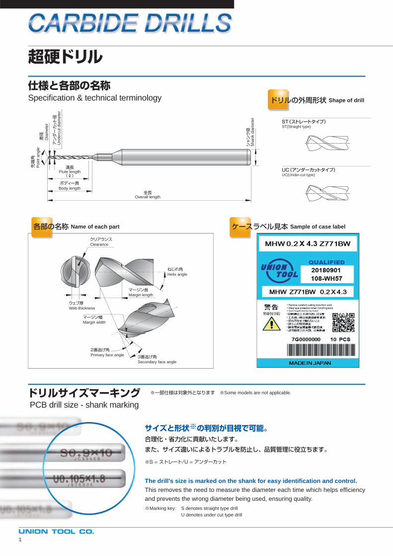
各部の名称 Name of each part ケースラベル見本 Sample of case label
ドリルの外周形状 Shape of drill
クリアランスClearance
ねじれ角Helix angle
ウェブ厚Web thickness
マージン幅Margin width
マージン長Margin length
2番逃げ角Primary face angle 3番逃げ角
Secondary face angle
サイズと形状※の判別が目視で可能。合理化・省力化に貢献いたします。
また、サイズ違いによるトラブルを防止し、品質管理に役立ちます。
※S = ストレート/U = アンダーカット
The drill's size is marked on the shank for easy identifi cation and control.This removes the need to measure the diameter each time which helps effi ciency
and prevents the wrong diameter being used, ensuring quality.
※Marking key: S denotes straight type drill
U denotes under cut type drill
ドリルサイズマーキングPCB drill size - shank marking
※一部仕様は対象外となります ※Some models are not applicable.
超硬ドリル
仕様と各部の名称Specifi cation & technical terminology
1
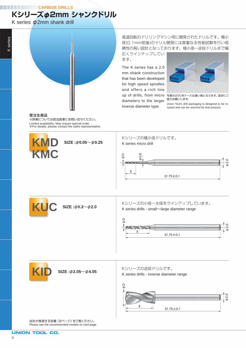
CARBIDE DRILLS
型 番Model型 番Model
特 徴Features特 徴Features
形 状Appearance形 状Appearance
サイズSizeサイズSize
Kシリーズφ2mm シャンクドリルK series φ2mm shank drill....................................p3, p4
MD(極小径)シリーズMD(Micro drill) series ....................................p5, p6
UC/UV(小径)シリーズUC/UV(Small diameter)series ....................................p9, p10
UC35/UM35シリーズUC35/UM35 series ....................................p11, p12
UA/UR35シリーズUA/UR35 series ....................................p13, p14
UM30シリーズ/STシリーズUM30 series /ST series ....................................p15, p16
SX24(長穴用)シリーズSX24(Slot drilling) series ....................................p17
周速表Velocity.........................................................................................p19, p20
ID30C(逆段)シリーズID30C(Inverse diameter drill) series ....................................p18
ULFコートの紹介Introduction to ULF coated products.........................................p21
ダイヤコートの紹介Introduction to Diamond coated products.................................p22
KMDKMCKUC
KID
MDMCMVMCV
UC
UV
UC35
UM35
UA
UR35
UM30
ST
SX24
ID30C
INDEX
アンダーカットタイプ φ0.8~φ1.6 Under cut type
アンダーカットタイプ φ0.8~φ1.6 Under cut type
内壁重視タイプ Improved inner hole wall quality
2
サイズによっては受注生産となりますので、あらかじめご了承ください。While every effort is made to have all models in stock, certain models are made to special order - Please contact sales representative.
高速回転ドリリングマシン用ドリルFor high speed spindle
穴位置精度、内壁重視、バランスタイプ各種Hole registration accuracy,inner hole wall quality, balance type
高速回転ドリリングマシン用逆段ドリルInverse diameter drill for high speed spindle
多層基板用ドリル アンダーカットタイプ φ1.65~φ3.175For multi layer board Under cut type
一般的汎用ドリル ストレートタイプ φ0.6~φ3.175
Standard drill Straight type
長穴加工用For slot drilling
チップブレーカー・シンニング付逆段ドリルChip breaker/ Thinning inverse diameter drill
バランスタイプ アンダーカットタイプ φ0.8~φ1.6Hole registration accuracy, Under cut type inner hole wall quality, balance type
多層基板用ドリル アンダーカットタイプ φ0.8~φ1.6For multi layer board Under cut type
ストレートタイプStraight type
アンダーカットタイプ φ0.05~φ0.25
Under cut type
アンダーカットタイプ φ0.3~φ2.0Under cut type
ストレートタイプ φ2.05~φ4.05Straight type
ストレートタイプ φ0.05~φ0.15Straight type
アンダーカットタイプ φ0.105~φ0.25Under cut type
ストレートタイプ φ0.105~φ0.15Straight type
アンダーカットタイプ φ0.15~φ0.25Under cut type
ストレートタイプ Straight type
アンダーカットタイプ Under cut type
アンダーカットタイプ φ0.3~φ0.55Under cut type
アンダーカットタイプ φ0.3~φ0.75Under cut type
φ0.2~φ0.4
φ0.105~φ0.4
アンダーカットタイプ φ0.5~φ1.6Under cut type
ストレートタイプ φ3.2~φ6.5Straight type
穴位置精度、内壁重視、バランスタイプ各種Hole registration accuracy, inner hole wall quality, balance type
新形状ドリルシリーズ New series
1枚刃ドリルシリーズ Single fl ute drill series
2刃並走ドリルシリーズ
Parallel fl ute drill series
FXシリーズ FX serise....................................p7, p8
MHWUHWKHWMWMCWUWKMWKCWFX
穴位置精度に優れ、長寿命化が可能な新シリーズNew series that features excellent hole regis-tration accuracy, enabling longer tool life
パッケージサブストレート、高多層基板、車載基板向け新シリーズNew series for package substrates, high layer count PCBs, and automotive PCBs
FPC加工用Series for drilling FPC materials
φ0.08~φ0.55
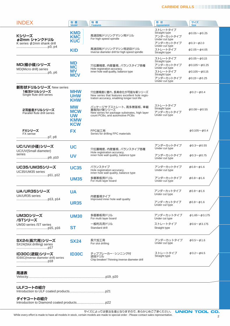
高速回転のドリリングマシン用に開発されたドリルです。極小径(0.1mm前後)のドリル開発には度重なる性能試験を行い信頼性の高い設計となっております。極小径~逆段ドリルまで幅広くラインナップしています。
The K series has a 2.0
mm shank construction
that has been developed
for high speed spindles
and of fers a r ich l ine
up of drills, from micro
diameters to the larger
inverse diameter type.
CARBIDE DRILLS
KUC SIZE :φ0.3~φ2.0
KID SIZE :φ2.05~φ4.05
Kシリーズの極小径ドリルです。K series micro drill
Kシリーズの小径~太径をラインアップしています。K series drills - small~large diameter range
Kシリーズの逆段ドリルです。K series drills - inverse diameter range
写真の200本ケースは通い箱となります。返却にご協力お願いします。
Union Tool’s drill packaging is designed to be re-
cycled and can be returned for that purpose.
φD
φ0.8
φ2.0
ℓ
31.75±0.1
φD
φ2.0
ℓ31.75±0.1
φD
φ2.0
ℓ31.75±0.1
Kシリーズφ2mm シャンクドリルK series φ2mm shank drill
KMDKMC
SIZE :φ0.05~φ0.25
当社が推奨する型番(次ページ)をご覧ください。Please see the recommended models on next page.
受注生産品※詳細については担当営業にお問い合せください。Limited availability; May require special order.※For details, please contact the sales representative.
K s
erie
s
3
CARBIDE DRILLS
4
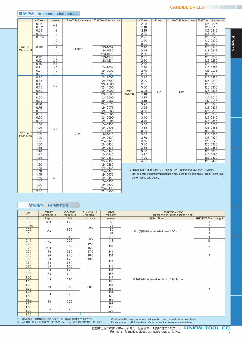
*1 基板の種類、重ね枚数によりチップロード、寿命の調整をしてください。 Chip load and hit count may vary depending on the board type, material and stack height.*2 φ2.0以上のサイズについてはドリルマシンメーカーの推奨条件を参照してください。 For diameters over φ2.0 mm please refer to the machine makers recommendations.
仕様は上記の限りではありません。担当営業にお問い合せください。For more information, please ask sales representative.
推奨型番 Recommended models
φD 回転数Spindle speed
送り速度Infeed rate
チップロードChip load *1
周速Velocity
基板設定の目安Board thickness and stack height
mm k rpm m/min μm/rev m/min 基板 Board 重ね枚数 Stack height0.05 350 1.75
5.0
55
t0.1(両面板double-sided board 5-5μm)
20.075
300 1.5071 4
0.09 85 50.10 94 60.12 2.40 8.0 113 80.15 250 2.00 118 100.20 3.00 12.0 157
t0.4(両面板double-sided board 12-12μm)
40.25 200 15.00.30 150 2.60 17.0 141
60.40 120 2.20 18.0 1510.50 90 1.70 19.0 1410.60 75 1.50
20.0 8
0.70 65 1.30 1430.80 60 1.20 1510.90 55 1.10 1551.00 45 0.90 1411.10 1551.20 40 0.80 1511.30 1631.40 38 0.76 1671.50 1791.60 36 0.72 1811.70 1921.80 35 0.70 1981.90 2092.00 *2
切削条件 Parameters
*推奨型番は性能向上のため、予告なしに仕様変更する場合がございます。 Model recommendation/specifi cation may change as part of our policy to improve parformance and quality.
φD mm ℓ mm シリーズ名 Series name 製品コード Product code
極小径Micro drill
0.05 0.9
K series
0.0750.08 1.20.09 1.40.095
0.105
1.51.61.7 123-1067
1.8 124-1050123-1060
0.12 1.5 123-12050.12 2.0 123-12040.15 2.70.2 3.5 124-20040.2 4.0 124-20020.25 4.5 124-2502
小径~太径Small~Large
0.30
5.0
KUC
124-30000.35 124-35000.40 124-40000.45 124-45000.50 124-50000.55 124-55000.60
5.5
124-00600.65 124-00650.70 124-00700.75 124-00750.80 124-00800.85 124-00850.90 124-00900.95 124-00951.00 124-01001.05 124-01051.10 124-01101.15 124-01151.20 124-01201.25 124-01251.30 124-01301.35 124-01351.40 124-01401.45 124-01451.50 124-01501.55 124-01551.60
8.0
124-01601.65 124-01651.70 124-01701.75 124-01751.80 124-01801.85 124-01851.90 124-01901.95 124-01952.00 124-0200
φD mm ℓ mm シリーズ名 Series name 製品コード Product code
逆段Inverse
2.05
8.0 KID
126-02052.10 126-02102.15 126-02152.20 126-02202.25 126-02252.30 126-02302.35 126-02352.40 126-02402.45 126-02452.50 126-02502.55 126-02552.60 126-02602.65 126-02652.70 126-02702.75 126-02752.80 126-02802.85 126-02852.90 126-02902.95 126-02953.00 126-03003.05 126-03053.10 126-03103.15 126-03153.18 126-03173.20 126-03203.25 126-03253.30 126-03303.35 126-03353.40 126-03403.45 126-03453.50 126-03503.55 126-03553.60 126-03603.65 126-03653.70 126-03703.75 126-03753.80 126-03803.85 126-03853.90 126-03903.95 126-03954.00 126-04004.05 126-0405
K series
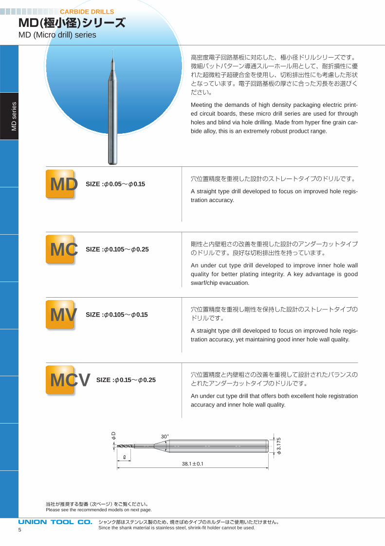
高密度電子回路基板に対応した、極小径ドリルシリーズです。微細パットパターン導通スルーホール用として、耐折損性に優れた超微粒子超硬合金を使用し、切粉排出性にも考慮した形状となっています。電子回路基板の厚さに合った刃長をお選びください。
Meeting the demands of high density packaging electric print-
ed circuit boards, these micro drill series are used for through
holes and blind via hole drilling. Made from hyper fi ne grain car-
bide alloy, this is an extremely robust product range.
穴位置精度を重視した設計のストレートタイプのドリルです。
A straight type drill developed to focus on improved hole regis-
tration accuracy.
剛性と内壁粗さの改善を重視した設計のアンダーカットタイプのドリルです。良好な切粉排出性を持っています。
An under cut type drill developed to improve inner hole wall
quality for better plating integrity. A key advantage is good
swarf/chip evacuation.
穴位置精度を重視し剛性を保持した設計のストレートタイプのドリルです。
A straight type drill developed to focus on improved hole regis-
tration accuracy, yet maintaining good inner hole wall quality.
穴位置精度と内壁粗さの改善を重視して設計されたバランスのとれたアンダーカットタイプのドリルです。
An under cut type drill that offers both excellent hole registration
accuracy and inner hole wall quality.
CARBIDE DRILLS
MD(極小径)シリーズMD (Micro drill) series
MD SIZE :φ0.05~φ0.15
MC SIZE :φ0.105~φ0.25
MV SIZE :φ0.105~φ0.15
MCV SIZE :φ0.15~φ0.25
当社が推奨する型番(次ページ)をご覧ください。Please see the recommended models on next page.
シャンク部はステンレス製のため、焼きばめタイプのホルダーはご使用いただけません。Since the shank material is stainless steel, shrink-fi t holder cannot be used.
φD
φ3.17530°
38.1±0.1
ℓ
MD
se
rie
s
5
推奨型番 Recommended models
切削条件 Parameters
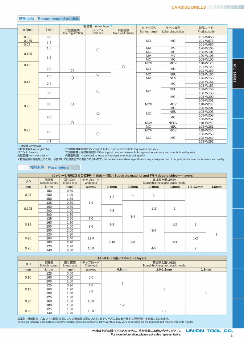
パッケージ基板ならびにFR-4 両面~4層/Substrate material and FR-4 double-sided 4 layers
φD 回転数Spindle speed
送り速度Infeed rate
チップロードChip load
基板厚と重ね枚数Board thickness and stack height
mm k rpm m/min μm/rev 0.1mm 0.2mm 0.4mm 0.8mm 1.0-1.2mm 1.6mm
0.05
160 0.80
5.0
1-21 1 -
- -
200 1.00
350 1.75
0.105
125 0.60
3-4
1-2 1160 0.80
4-6200 1.00
300 1.50
0.15
125 0.90 7.0
5-8
3-4
1-2 1
1
160 1.20
8.0200 1.60
250 2.00
0.20
125 1.90
12.0
6-10 5-8 2-3
1-2160 2.40
180 2.70
0.25125 2.50
15.0 4-5 2140 2.80
FR-4 6~8層/FR-4 6 8 layers
φD 回転数Spindle speed
送り速度Infeed rate
チップロードChip load
基板厚と重ね枚数Board thickness and stack height
mm k rpm m/min μm/rev 0.8mm 1.0-1.2mm 1.6mm
0.10
125 0.60
5.0
1
1
1
160 0.80
200 1.00
0.15
125 0.90 7.0
160 1.208.0
200 1.50
0.20
125 1.30
10.0
1-2
160 1.60
180 1.80
0.25125 1.50
12.0 1-2140 1.70
CARBIDE DRILLSM
D s
erie
s
6
仕様は上記の限りではありません。担当営業にお問い合せください。For more information, please ask sales representative.
仕様は上記の限りではありません。担当営業にお問い合せください。For more information, please ask sales representative.
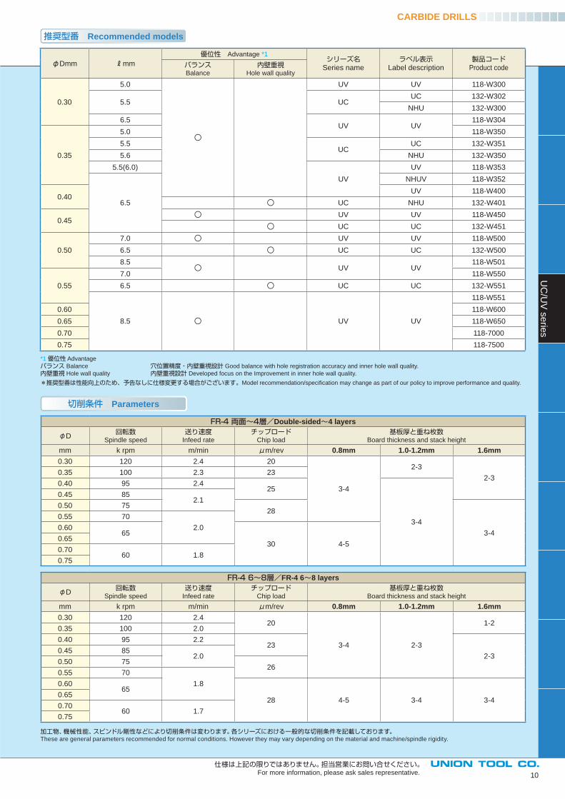
*1 優位性 Advantage
穴位置重視 Hole registration 穴位置精度重視設計 Developed to focus on improved hole registration accuracy.
バランス Balance 穴位置精度・内壁重視設計 Offers a good balance between hole registration accuracy and inner hole wall quality.
内壁重視 Hole wall quality 内壁重視設計 Developed to focus on improved inner hole wall quality.
*推奨型番は性能向上のため、予告なしに仕様変更する場合がございます。Model recommendation/specifi cation may change as part of our policy to improve performance and quality.
加工物、機械性能、スピンドル剛性などにより切削条件は変わります。各シリーズにおける一般的な切削条件を記載しております。These are general parameters recommended for normal conditions. However they may vary depending on the material and machine/spindle rigidity.
φDmm mm優位性 Advantage *1 シリーズ名
Series nameラベル表示
Label description製品コード
Product code穴位置重視Hole registration
バランスBalance
内壁重視Hole wall quality
0.05 0.9 MD MD
101-W0500.075
1.2 101-W075
0.08 101-W080
0.105
1.5 MV MV 120-W105
1.8
MC MC 108-W101MV MV 120-W106MC MC 108-W100
0.12MCV MCV 118-W120
2.0 MD MD101-W120
0.15
101-W150
2.5 MC NEU 108-W150MV NEV 120-W150
2.7
MC
MC108-W151108-W152
3.0 NEU 108-W153
MC108-W158
0.20
108-W200
3.5 108-W201
MCV MCV 118-W200
MC
MC 108-W204
4.0
NEU 108-W203
MC108-W208
0.25
108-W252MCV NEUV 118-W252
4.5
MC NEU 108-W251MCV MCV 118-W250
MC MC108-W253108-W259
4.7 108-W262
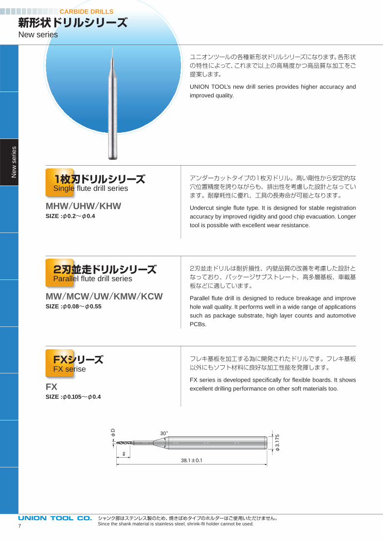
アンダーカットタイプの1枚刃ドリル。高い剛性から安定的な穴位置精度を誇りながらも、排出性を考慮した設計となっています。耐摩耗性に優れ、工具の長寿命が可能となります。
Undercut single fl ute type. It is designed for stable registration
accuracy by improved rigidity and good chip evacuation. Longer
tool is possible with excellent wear resistance.
2刃並走ドリルは耐折損性、内壁品質の改善を考慮した設計となっており、パッケージサブストレート、高多層基板、車載基板などに適しています。
Parallel fl ute drill is designed to reduce breakage and improve
hole wall quality. It performs well in a wide range of applications
such as package substrate, high layer counts and automotive
PCBs.
フレキ基板を加工する為に開発されたドリルです。フレキ基板以外にもソフト材料に良好な加工性能を発揮します。
FX series is developed specifi cally for fl exible boards. It shows
excellent drilling performance on other soft materials too.
1枚刃ドリルシリーズSingle fl ute drill series
2刃並走ドリルシリーズParallel fl ute drill series
FXシリーズFX serise
SIZE :φ0.08~φ0.55
SIZE :φ0.105~φ0.4
MW/MCW/UW/KMW/KCW
FX
ユニオンツールの各種新形状ドリルシリーズになります。各形状の特性によって、これまで以上の高精度かつ高品質な加工をご提案します。
UNION TOOL’s new drill series provides higher accuracy and
improved quality.
CARBIDE DRILLSN
ew
se
rie
s
新形状ドリルシリーズNew series
SIZE :φ0.2~φ0.4MHW/UHW/KHW
φD
φ3.17530°
38.1±0.1
ℓ
シャンク部はステンレス製のため、焼きばめタイプのホルダーはご使用いただけません。Since the shank material is stainless steel, shrink-fi t holder cannot be used.7

1枚刃ドリルシリーズ/Single fl ute drill series
φDmm mm
0.203.5
4.0
0.254.7
5.0
0.30
5.0
5.5
6.0
6.2
6.5
0.35
5.5
6.2
6.50.40
仕 様 Specifications
2刃並走ドリルシリーズ/Parallel fl ute drill series
φDmm mm
0.08 1.5
0.09 1.6
0.1051.8
2.1
0.15 2.7
0.20 3.7
0.25
4.7
5.0
5.5
0.30
5.0
5.5
6.0
6.2
6.5
0.40
6.5
7.0
8.5
0.45
6.5
7.0
9.0
0.507.0
9.0
0.557.0
10.0
FXシリーズ/FX series
φDmm mm
0.1051.6
1.8
0.15 2.5
0.203.0
3.5
0.25
4.00.30
0.35
0.40
CARBIDE DRILLS
8
仕様は上記の限りではありません。担当営業にお問い合せください。For more information, please ask sales representative.
Ne
w s
erie
s
*サイズによっては受注生産となります。詳細については、担当営業にお問い合わせください。 Some models are made to order. For details, please contact the sales representative.
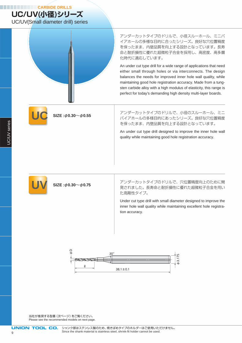
アンダーカットタイプのドリルで、小径スルーホール、ミニバイアホールの多様な目的に合ったシリーズ。良好な穴位置精度を保ったまま、内壁品質を向上する設計となっています。長寿命と耐折損性に優れた超微粒子合金を採用し、高密度、高多層化時代に適応しています。
An under cut type drill for a wide range of applications that need
either small through holes or via interconnects. The design
balances the needs for improved inner hole wall quality, while
maintaining good hole registration accuracy. Made from a tung-
sten carbide alloy with a high modulus of elasticity, this range is
perfect for today’s demanding high density multi-layer boards.
アンダーカットタイプのドリルで、小径のスルーホール、ミニバイアホールの多様目的にあったシリーズ。良好な穴位置精度を保ったまま、内壁品質を向上する設計となっています。
An under cut type drill designed to improve the inner hole wall
quality while maintaining good hole registration accuracy.
アンダーカットタイプのドリルで、穴位置精度向上のために開発されました。長寿命と耐折損性に優れた超微粒子合金を用いた高剛性タイプ。
Under cut type drill with small diameter designed to improve the
inner hole wall quality while maintaining excellent hole registra-
tion accuracy.
φD
φ3.17530°
38.1±0.1ℓ
CARBIDE DRILLSU
C/U
V s
erie
s
UC/UV(小径)シリーズUC/UV(Small diameter drill) series
UC SIZE :φ0.30~φ0.55
UV SIZE :φ0.30~φ0.75
当社が推奨する型番(次ページ)をご覧ください。Please see the recommended models on next page.
シャンク部はステンレス製のため、焼きばめタイプのホルダーはご使用いただけません。Since the shank material is stainless steel, shrink-fi t holder cannot be used.9
切削条件 Parameters
*1 優位性 Advantage
バランス Balance 穴位置精度・内壁重視設計 Good balance with hole registration accuracy and inner hole wall quality.
内壁重視 Hole wall quality 内壁重視設計 Developed focus on the Improvement in inner hole wall quality.
*推奨型番は性能向上のため、予告なしに仕様変更する場合がございます。Model recommendation/specifi cation may change as part of our policy to improve performance and quality.
FR-4 両面~4層/Double-sided 4 layers
φD回転数
Spindle speed
送り速度Infeed rate
チップロードChip load
基板厚と重ね枚数Board thickness and stack height
mm k rpm m/min μm/rev 0.8mm 1.0-1.2mm 1.6mm0.30 120 2.4 20
3-4
2-3
2-30.35 100 2.3 23
0.40 95 2.425
3-4
0.45 852.1
0.50 7528
3-4
0.55 70
2.00.6065
30 4-50.65
0.7060 1.8
0.75
FR-4 6~8層/FR-4 6 8 layers
φD回転数
Spindle speed
送り速度Infeed rate
チップロードChip load
基板厚と重ね枚数Board thickness and stack height
mm k rpm m/min μm/rev 0.8mm 1.0-1.2mm 1.6mm0.30 120 2.4
20
3-4 2-3
1-20.35 100 2.0
0.40 95 2.223
2-30.45 85
2.00.50 75
260.55 70
1.80.6065
28 4-5 3-4 3-40.65
0.7060 1.7
0.75
推奨型番 Recommended models
CARBIDE DRILLSU
C/U
V s
erie
s
10
仕様は上記の限りではありません。担当営業にお問い合せください。For more information, please ask sales representative.
φDmm mm
優位性 Advantage *1シリーズ名
Series nameラベル表示
Label description製品コード
Product codeバランスBalance
内壁重視Hole wall quality
0.30
5.0 UV UV 118-W300
5.5 UCUC 132-W302
NHU 132-W300
6.5 UV UV
118-W304
0.35
5.0 118-W350
5.5 UC
UC 132-W351
5.6 NHU 132-W350
5.5(6.0)
UV
UV 118-W353
6.5
NHUV 118-W352
0.40UV 118-W400
UC NHU 132-W401
0.45UV UV 118-W450
UC UC 132-W451
0.50
7.0 UV UV 118-W500
6.5 UC UC 132-W500
8.5 UV UV
118-W501
0.55
7.0 118-W550
6.5 UC UC 132-W551
8.5 UV UV
118-W551
0.60 118-W600
0.65 118-W650
0.70 118-7000
0.75 118-7500
加工物、機械性能、スピンドル剛性などにより切削条件は変わります。各シリーズにおける一般的な切削条件を記載しております。These are general parameters recommended for normal conditions. However they may vary depending on the material and machine/spindle rigidity.
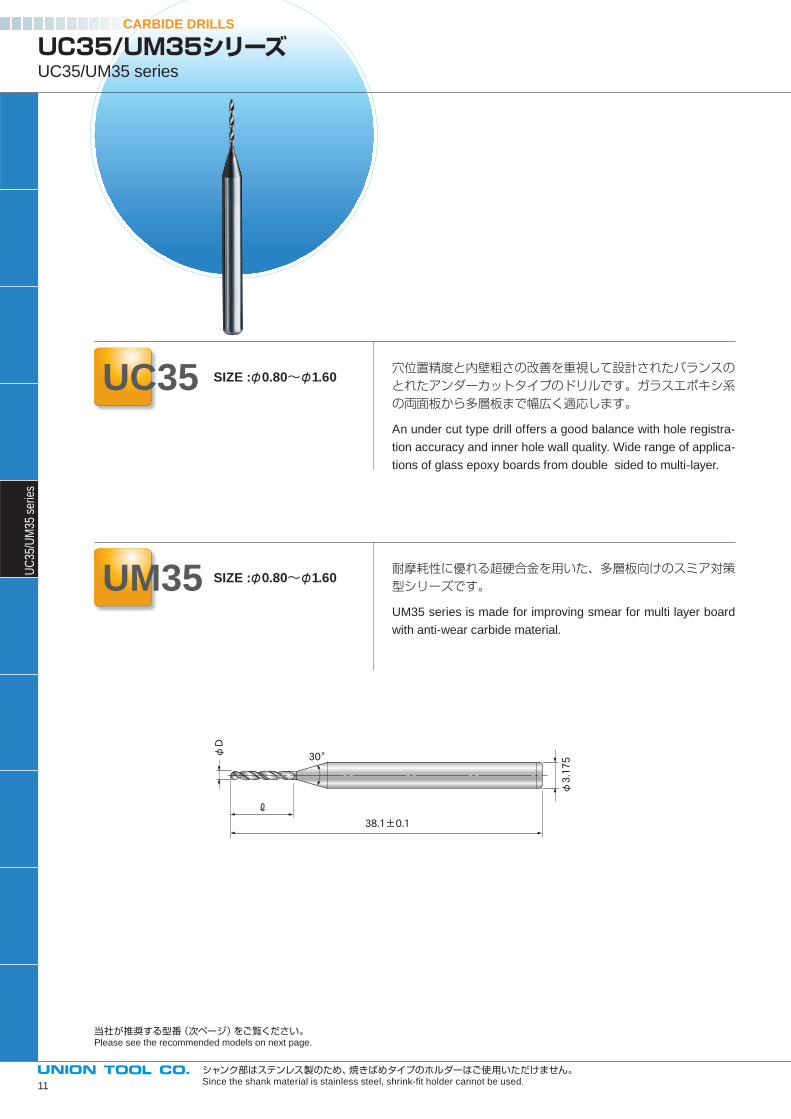
穴位置精度と内壁粗さの改善を重視して設計されたバランスのとれたアンダーカットタイプのドリルです。ガラスエポキシ系の両面板から多層板まで幅広く適応します。
An under cut type drill offers a good balance with hole registra-
tion accuracy and inner hole wall quality. Wide range of applica-
tions of glass epoxy boards from double sided to multi-layer.
耐摩耗性に優れる超硬合金を用いた、多層板向けのスミア対策型シリーズです。
UM35 series is made for improving smear for multi layer board
with anti-wear carbide material.
φD
φ3.17530°
38.1±0.1
ℓ
CARBIDE DRILLSU
C35
/UM
35 s
erie
s
UC35/UM35シリーズUC35/UM35 series
UC35 SIZE :φ0.80~φ1.60
UM35 SIZE :φ0.80~φ1.60
当社が推奨する型番(次ページ)をご覧ください。Please see the recommended models on next page.
シャンク部はステンレス製のため、焼きばめタイプのホルダーはご使用いただけません。Since the shank material is stainless steel, shrink-fi t holder cannot be used.11
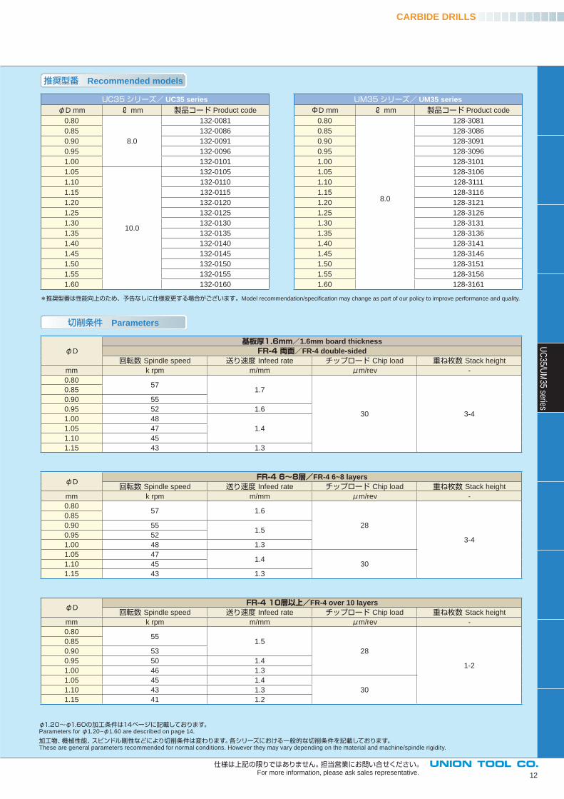
推奨型番 Recommended models
*推奨型番は性能向上のため、予告なしに仕様変更する場合がございます。Model recommendation/specifi cation may change as part of our policy to improve performance and quality.
切削条件 Parameters
CARBIDE DRILLS
UC35シリーズ/ UC35 seriesφD mm ℓ mm 製品コード Product code
0.80
8.0
132-0081
0.85 132-0086
0.90 132-0091
0.95 132-0096
1.00 132-0101
1.05
10.0
132-0105
1.10 132-0110
1.15 132-0115
1.20 132-0120
1.25 132-0125
1.30 132-0130
1.35 132-0135
1.40 132-0140
1.45 132-0145
1.50 132-0150
1.55 132-0155
1.60 132-0160
UM35シリーズ/ UM35 seriesΦD mm ℓ mm 製品コード Product code
0.80
8.0
128-3081
0.85 128-3086
0.90 128-3091
0.95 128-3096
1.00 128-3101
1.05 128-3106
1.10 128-3111
1.15 128-3116
1.20 128-3121
1.25 128-3126
1.30 128-3131
1.35 128-3136
1.40 128-3141
1.45 128-3146
1.50 128-3151
1.55 128-3156
1.60 128-3161
φD
基板厚1.6mm/1.6mm board thicknessFR-4 両面/FR-4 double-sided
回転数 Spindle speed 送り速度 Infeed rate チップロード Chip load 重ね枚数 Stack height
mm k rpm m/mm μm/rev -
0.8057
1.7
30 3-4
0.85
0.90 55
0.95 52 1.6
1.00 48
1.41.05 47
1.10 45
1.15 43 1.3
UC
35/UM
35 series
12
仕様は上記の限りではありません。担当営業にお問い合せください。For more information, please ask sales representative.
φ1.20~φ1.60の加工条件は14ページに記載しております。Parameters for φ1.20~φ1.60 are described on page 14.
加工物、機械性能、スピンドル剛性などにより切削条件は変わります。各シリーズにおける一般的な切削条件を記載しております。These are general parameters recommended for normal conditions. However they may vary depending on the material and machine/spindle rigidity.
φD FR-4 6~8層/FR-4 6~8 layers
回転数 Spindle speed 送り速度 Infeed rate チップロード Chip load 重ね枚数 Stack height
mm k rpm m/mm μm/rev -
0.8057 1.6
28
3-4
0.85
0.90 551.5
0.95 52
1.00 48 1.3
1.05 471.4
301.10 45
1.15 43 1.3
φD FR-4 10層以上/FR-4 over 10 layers
回転数 Spindle speed 送り速度 Infeed rate チップロード Chip load 重ね枚数 Stack height
mm k rpm m/mm μm/rev -
0.8055
1.5
28
1-2
0.85
0.90 53
0.95 50 1.4
1.00 46 1.3
1.05 45 1.4
301.10 43 1.3
1.15 41 1.2
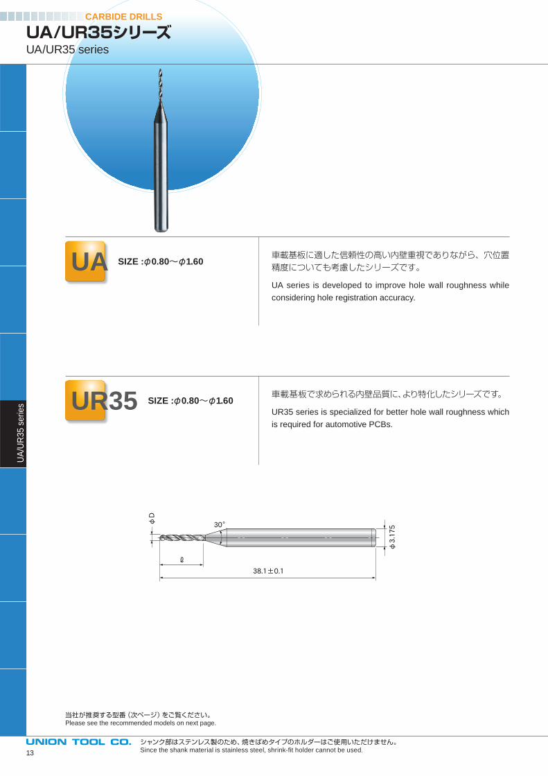
車載基板に適した信頼性の高い内壁重視でありながら、穴位置精度についても考慮したシリーズです。
UA series is developed to improve hole wall roughness while
considering hole registration accuracy.
車載基板で求められる内壁品質に、より特化したシリーズです。
UR35 series is specialized for better hole wall roughness which
is required for automotive PCBs.
φD
φ3.17530°
38.1±0.1
ℓ
CARBIDE DRILLSU
A/U
R3
5 s
erie
s
UA/UR35シリーズUA/UR35 series
UA SIZE :φ0.80~φ1.60
UR35 SIZE :φ0.80~φ1.60
当社が推奨する型番(次ページ)をご覧ください。Please see the recommended models on next page.
シャンク部はステンレス製のため、焼きばめタイプのホルダーはご使用いただけません。Since the shank material is stainless steel, shrink-fi t holder cannot be used.13
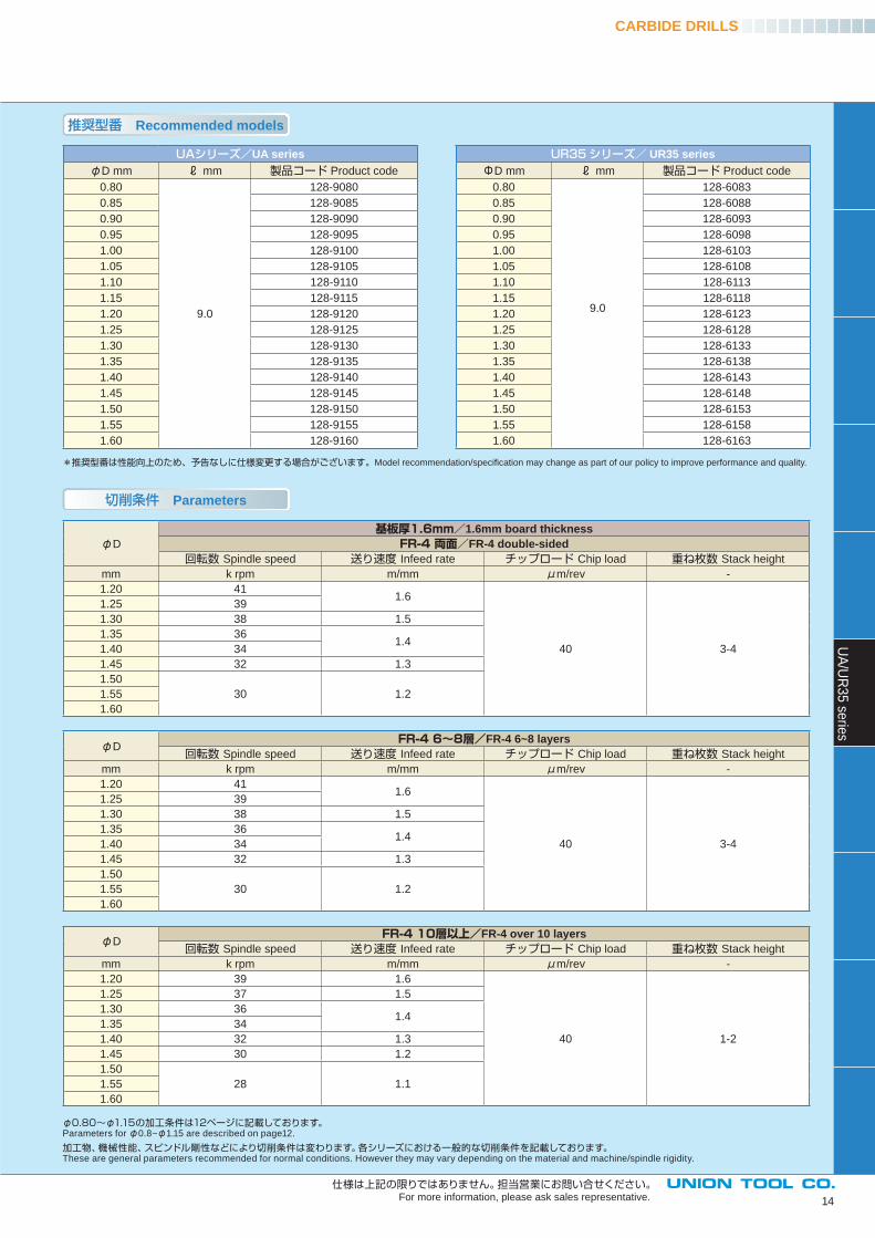
推奨型番 Recommended models
*推奨型番は性能向上のため、予告なしに仕様変更する場合がございます。Model recommendation/specifi cation may change as part of our policy to improve performance and quality.
切削条件 Parameters
CARBIDE DRILLS
UAシリーズ/UA seriesφD mm ℓ mm 製品コード Product code
0.80
9.0
128-9080
0.85 128-9085
0.90 128-9090
0.95 128-9095
1.00 128-9100
1.05 128-9105
1.10 128-9110
1.15 128-9115
1.20 128-9120
1.25 128-9125
1.30 128-9130
1.35 128-9135
1.40 128-9140
1.45 128-9145
1.50 128-9150
1.55 128-9155
1.60 128-9160
UR35シリーズ/ UR35 seriesΦD mm ℓ mm 製品コード Product code
0.80
9.0
128-6083
0.85 128-6088
0.90 128-6093
0.95 128-6098
1.00 128-6103
1.05 128-6108
1.10 128-6113
1.15 128-6118
1.20 128-6123
1.25 128-6128
1.30 128-6133
1.35 128-6138
1.40 128-6143
1.45 128-6148
1.50 128-6153
1.55 128-6158
1.60 128-6163
φD
基板厚1.6mm/1.6mm board thicknessFR-4 両面/FR-4 double-sided
回転数 Spindle speed 送り速度 Infeed rate チップロード Chip load 重ね枚数 Stack height
mm k rpm m/mm μm/rev -
1.20 411.6
40 3-4
1.25 39
1.30 38 1.5
1.35 361.4
1.40 34
1.45 32 1.3
1.50
30 1.21.55
1.60
UA
/UR
35
serie
s
14
仕様は上記の限りではありません。担当営業にお問い合せください。For more information, please ask sales representative.
φ0.80~φ1.15の加工条件は12ページに記載しております。Parameters for φ0.8~φ1.15 are described on page12.
加工物、機械性能、スピンドル剛性などにより切削条件は変わります。各シリーズにおける一般的な切削条件を記載しております。These are general parameters recommended for normal conditions. However they may vary depending on the material and machine/spindle rigidity.
φD FR-4 6~8層/FR-4 6~8 layers
回転数 Spindle speed 送り速度 Infeed rate チップロード Chip load 重ね枚数 Stack height
mm k rpm m/mm μm/rev -
1.20 411.6
40 3-4
1.25 39
1.30 38 1.5
1.35 361.4
1.40 34
1.45 32 1.3
1.50
30 1.21.55
1.60
φD FR-4 10層以上/FR-4 over 10 layers
回転数 Spindle speed 送り速度 Infeed rate チップロード Chip load 重ね枚数 Stack height
mm k rpm m/mm μm/rev -
1.20 39 1.6
40 1-2
1.25 37 1.5
1.30 361.4
1.35 34
1.40 32 1.3
1.45 30 1.2
1.50
28 1.11.55
1.60
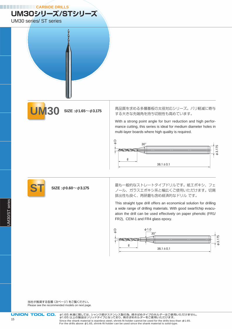
高品質を求める多層基板の太径対応シリーズ。バリ軽減に寄与する大きな先端角を持ち切削性も高めています。
With a strong point angle for burr reduction and high perfor-
mance cutting, this series is ideal for medium diameter holes in
multi-layer boards where high quality is required.
最も一般的なストレートタイプドリルです。紙エポキシ、フェノール、ガラスエポキシ系と幅広くご使用いただけます。切屑排出性も良く、再研磨も含め経済的なドリル です。
This straight type drill offers an economical solution for drilling
a wide range of drilling materials. With good swarf/chip evacu-
ation the drill can be used effectively on paper phenolic (FR1/
FR2), CEM-1 and FR4 glass epoxy.
φD
φ3.17530°
38.1±0.1
ℓ
φD φ1.0
φ3.175
30°
38.1±0.1ℓ
CARBIDE DRILLSU
M3
0/S
T s
eries
UM30シリーズ/STシリーズUM30 series/ ST series
UM30 SIZE :φ1.65~φ3.175
ST SIZE :φ0.60~φ3.175
当社が推奨する型番(次ページ)をご覧ください。Please see the recommended models on next page.
φ1.65 未満に関しては、シャンク部がステンレス製の為、焼きばめタイプのホルダーはご使用いただけません。φ1.65 以上の製品はソリッドタイプとなっており、焼きばめホルダーをご使用いただけます。Since the shank material is stainless steel, shrink-fi t holder cannot be used for the drills less than φ1.65. For the drills above φ1.65, shrink-fi t holder can be used since the shank material is solid-type.
15
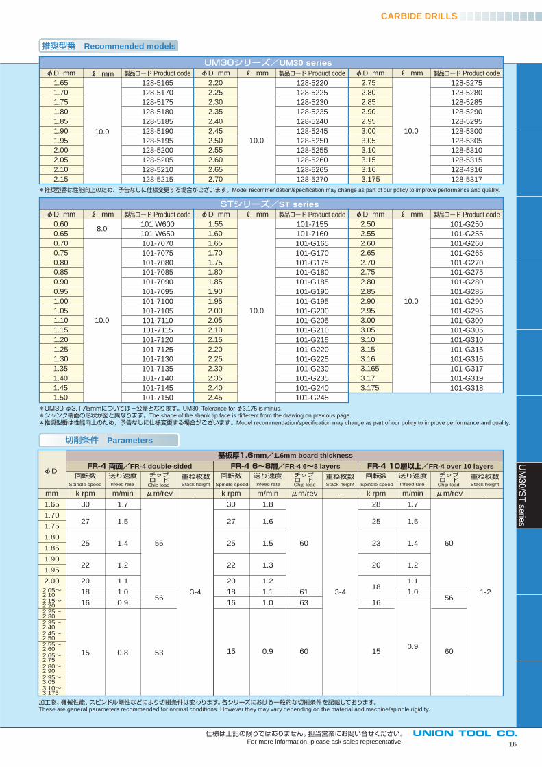
推奨型番 Recommended models
CARBIDE DRILLSU
M3
0/S
T se
ries
16
D mm
1.65
1.70
1.75
1.80
1.85
1.90
1.95
2.00
2.05
2.10
2.15
mm
10.0
製品コード Product code
128-5165
128-5170
128-5175
128-5180
128-5185
128-5190
128-5195
128-5200
128-5205
128-5210
128-5215
D mm
2.20
2.25
2.30
2.35
2.40
2.45
2.50
2.55
2.60
2.65
2.70
mm
10.0
製品コード Product code
128-5220
128-5225
128-5230
128-5235
128-5240
128-5245
128-5250
128-5255
128-5260
128-5265
128-5270
D mm
2.75
2.80
2.85
2.90
2.95
3.00
3.05
3.10
3.15
3.16
3.175
mm
10.0
製品コード Product code
128-5275
128-5280
128-5285
128-5290
128-5295
128-5300
128-5305
128-5310
128-5315
128-4316
128-5317
D mm
0.60
0.65
0.70
0.75
0.80
0.85
0.90
0.95
1.00
1.05
1.10
1.15
1.20
1.25
1.30
1.35
1.40
1.45
1.50
mm
8.0
10.0
製品コード Product code
101 W600
101 W650
101-7070
101-7075
101-7080
101-7085
101-7090
101-7095
101-7100
101-7105
101-7110
101-7115
101-7120
101-7125
101-7130
101-7135
101-7140
101-7145
101-7150
D mm
1.55
1.60
1.65
1.70
1.75
1.80
1.85
1.90
1.95
2.00
2.05
2.10
2.15
2.20
2.25
2.30
2.35
2.40
2.45
mm
10.0
製品コード Product code
101-7155
101-7160
101-G165
101-G170
101-G175
101-G180
101-G185
101-G190
101-G195
101-G200
101-G205
101-G210
101-G215
101-G220
101-G225
101-G230
101-G235
101-G240
101-G245
D mm
2.50
2.55
2.60
2.65
2.70
2.75
2.80
2.85
2.90
2.95
3.00
3.05
3.10
3.15
3.16
3.165
3.17
3.175
mm
10.0
製品コード Product code
101-G250
101-G255
101-G260
101-G265
101-G270
101-G275
101-G280
101-G285
101-G290
101-G295
101-G300
101-G305
101-G310
101-G315
101-G316
101-G317
101-G319
101-G318
UM30シリーズ/UM30 series
STシリーズ/ST series
*推奨型番は性能向上のため、予告なしに仕様変更する場合がございます。Model recommendation/specifi cation may change as part of our policy to improve performance and quality.
mm
1.65
1.70
1.75
1.80
1.85
1.90
1.95
2.00
2.05~ 2.102.15~2.202.25~2.302.35~2.402.45~2.502.55~2.602.65~2.752.80~2.902.95~3.053.10~3.175
回転数
k rpm
30
27
25
22
20
18
16
15
送り速度
m/min
1.7
1.5
1.4
1.2
1.1
1.0
0.9
0.8
チップロード
μm/rev
55
56
53
-
3-4
FR-4 両面/FR-4 double-sided回転数
k rpm
30
27
25
22
20
18
16
15
送り速度
m/min
1.8
1.6
1.5
1.3
1.2
1.1
1.0
0.9
チップロード
μm/rev
60
61
63
60
-
3-4
FR-4 6~8層/FR-4 6~8 layers基板厚1.6mm/1.6mm board thickness
回転数
k rpm
28
25
23
20
18
16
15
送り速度
m/min
1.7
1.5
1.4
1.2
1.1
1.0
0.9
チップロード
μm/rev
60
56
60
-
1-2
FR-4 10層以上/FR-4 over 10 layersφD
Chip load Chip load Chip loadInfeed rate Infeed rate Infeed rateSpindle speed Spindle speed Spindle speed
重ね枚数Stack height
重ね枚数Stack height
重ね枚数Stack height
切削条件 Parameters
*UM30 φ3.175mmについては-公差となります。UM30: Tolerance for φ3.175 is minus.
*シャンク端面の形状が図と異なります。The shape of the shank tip face is different from the drawing on previous page.
*推奨型番は性能向上のため、予告なしに仕様変更する場合がございます。Model recommendation/specifi cation may change as part of our policy to improve performance and quality.
仕様は上記の限りではありません。担当営業にお問い合せください。For more information, please ask sales representative.
加工物、機械性能、スピンドル剛性などにより切削条件は変わります。各シリーズにおける一般的な切削条件を記載しております。These are general parameters recommended for normal conditions. However they may vary depending on the material and machine/spindle rigidity.
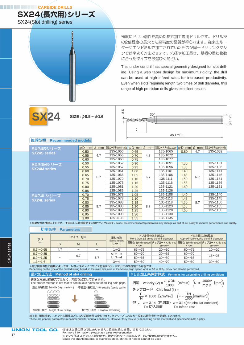
極度にドリル剛性を高めた長穴加工専用ドリルです。ドリル径の2倍程度の長穴でも高精度の品質が得られます。従来のルーターやエンドミルで加工されていたものが同一ドリリングマシンで効率よく対応できます。穴径や加工長さ、基板の重ね枚数に合ったタイプをお選びください。
This under cut drill has special geometry designed for slot drill-
ing. Using a web taper design for maximum rigidity, the drill
can be used at high infeed rates for increased productivity.
Even when slots requiring length two times of drill diameter, this
range of high precision drills gives excellent results.
SX24(長穴用)シリーズSX24(Slot drilling) series
SX24 SIZE :φ0.5~φ1.6φD
φ3.17530°
38.1±0.1
ℓ
推奨型番 Recommended models
切削条件 Parameters
周速 Velocity (V) = πφDN
[m/min]
N = 1000V
[rpm] 1000 πφD
チップロード Chip load ( f ) =
F × 1000[μm/rev]
F =
f N[mm/min]
N 1000
但し、π= 3.14(円周率)π= 3.14(the circular constant)
F=切込速度 F= Infeed rate
長穴加工方法 Method of slot drilling ドリル加工条件計算式 Formulas for calculating drilling conditions
適正な方法は連続穴ではなく、穴間を加工して行きます。The proper method is not that of continuous holes but of drilling hole gaps.
適正(高精度)Suitable (high precision) 不適正(曲り易い)Unsuitable (bends easily)
長穴加工長さ Length of slot drilling 長穴加工長さ Length of slot drilling
φDmm
タイプ Type 重ね枚数Stack height
(t1.6× )
ドリル径の2.5倍以上More than 2.5 times the drill diameter
ドリル径の2倍程度Approximately twice the drill diameter
S M L回転数 Spindle speed
k rpmチップロード Chip load
μm/rev回転数 Spindle speed
k rpmチップロード Chip load
μm/rev
0.5~0.65 4.7 − − 1~2 65~75 20~30 60~75 10~20
0.7~0.85
−6.7
8.7M: 2~3L : 3~4
60~70 20~35 60~7015~25
0.9~1.25 50~65 30~50 50~65
1.3~1.6 − 3~4 50~60 40~70 50~60 30~50
CARBIDE DRILLSS
X2
4 s
erie
s
*推奨型番は性能向上のため、予告なしに仕様変更する場合がございます。Model recommendation/specifi cation may change as part of our policy to improve performance and quality.
φD mm0.650.700.750.900.951.001.051.101.151.201.251.051.101.151.201.251.301.35
ℓ mm 4.7 6.7 8.7
製品コード Product code
135-1065135-1072135-1077135-1091135-1096135-1101135-1106135-1111135-1116
135-1121135-1126
135-1108135-1113
135-1118135-1123
135-1128135-1130
135-1135
φD mm0.80
1.301.351.401.451.501.551.60
1.401.451.501.551.60
ℓ mm4.7
6.7
8.7
製品コード Product code
135-1082
135-1131135-1136135-1141135-1146135-1151135-1156135-1161
135-1140135-1145
135-1150135-1155
135-1160
φD mm0.500.550.600.500.550.600.650.700.750.800.850.700.750.800.850.900.951.00
ℓ mm 4.7 6.7 8.7
製品コード Product code
135-1050135-1055135-1060135-1052135-1057135-1061135-1066135-1070135-1075
135-1081135-1086
135-1073135-1078
135-1083135-1088
135-1093135-1098
135-1103
SX24SシリーズSX24S series
SX24MシリーズSX24M series
SX24LシリーズSX24L series
*電子回路基板の種類によっては、Mサイズのメインサイズ付近は50~120μmの高速加工も可能です。Depending on the type of the printed-wiring board, in the main size area of the M size, high speed work at 50 to 120μm/rev can also be performed.
仕様は上記の限りではありません。担当営業にお問い合せください。For more information, please ask sales representative.
加工物、機械性能、スピンドル剛性などにより切削条件は変わります。各シリーズにおける一般的な切削条件を記載しております。These are general parameters recommended for normal conditions. However they may vary depending on the material and machine/spindle rigidity.
シャンク部はステンレス製のため、焼きばめタイプのホルダーはご使用いただけません。Since the shank material is stainless steel, shrink-fi t holder cannot be used.
17
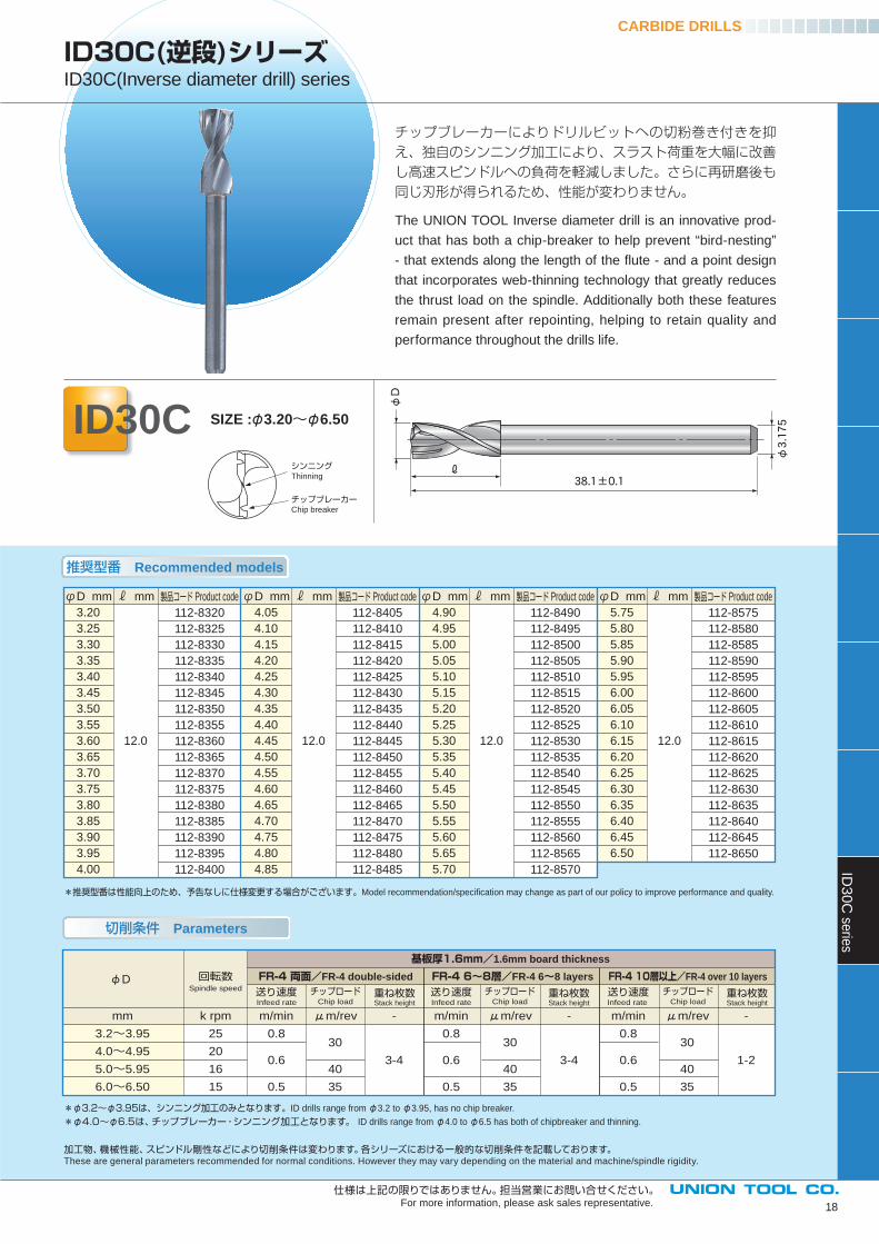
チップブレーカーによりドリルビットへの切粉巻き付きを抑え、独自のシンニング加工により、スラスト荷重を大幅に改善し高速スピンドルへの負荷を軽減しました。さらに再研磨後も同じ刃形が得られるため、性能が変わりません。
The UNION TOOL Inverse diameter drill is an innovative prod-
uct that has both a chip-breaker to help prevent “bird-nesting”
- that extends along the length of the fl ute - and a point design
that incorporates web-thinning technology that greatly reduces
the thrust load on the spindle. Additionally both these features
remain present after repointing, helping to retain quality and
performance throughout the drills life.
φD
φ3.175
38.1±0.1ℓ
推奨型番 Recommended models
切削条件 Parameters
CARBIDE DRILLSID
30
C se
ries
ID30C(逆段)シリーズID30C(Inverse diameter drill) series
ID30C SIZE :φ3.20~φ6.50
18
シンニングThinning
チップブレーカーChip breaker
φD mm
4.05
4.10
4.15
4.20
4.25
4.30
4.35
4.40
4.45
4.50
4.55
4.60
4.65
4.70
4.75
4.80
4.85
ℓ mm
12.0
製品コード Product code
112-8405
112-8410
112-8415
112-8420
112-8425
112-8430
112-8435
112-8440
112-8445
112-8450
112-8455
112-8460
112-8465
112-8470
112-8475
112-8480
112-8485
φD mm
4.90
4.95
5.00
5.05
5.10
5.15
5.20
5.25
5.30
5.35
5.40
5.45
5.50
5.55
5.60
5.65
5.70
ℓ mm
12.0
製品コード Product code
112-8490
112-8495
112-8500
112-8505
112-8510
112-8515
112-8520
112-8525
112-8530
112-8535
112-8540
112-8545
112-8550
112-8555
112-8560
112-8565
112-8570
φD mm
3.20
3.25
3.30
3.35
3.40
3.45
3.50
3.55
3.60
3.65
3.70
3.75
3.80
3.85
3.90
3.95
4.00
ℓ mm
12.0
製品コード Product code
112-8320
112-8325
112-8330
112-8335
112-8340
112-8345
112-8350
112-8355
112-8360
112-8365
112-8370
112-8375
112-8380
112-8385
112-8390
112-8395
112-8400
φD mm
5.75
5.80
5.85
5.90
5.95
6.00
6.05
6.10
6.15
6.20
6.25
6.30
6.35
6.40
6.45
6.50
ℓ mm
12.0
製品コード Product code
112-8575
112-8580
112-8585
112-8590
112-8595
112-8600
112-8605
112-8610
112-8615
112-8620
112-8625
112-8630
112-8635
112-8640
112-8645
112-8650
*推奨型番は性能向上のため、予告なしに仕様変更する場合がございます。Model recommendation/specifi cation may change as part of our policy to improve performance and quality.
mm
3.2~3.95
4.0~4.95
5.0~5.95
6.0~6.50
k rpm
25
20
16
15
送り速度
m/min
0.8
0.6
0.5
μm/rev
30
40
35
-
3-4
FR-4 両面/FR-4 double-sided送り速度
m/min
0.8
0.6
0.5
μm/rev
30
40
35
-
3-4
FR-4 6~8層/FR-4 6~8 layers基板厚1.6mm/1.6mm board thickness
送り速度
m/min
0.8
0.6
0.5
μm/rev
30
40
35
-
1-2
FR-4 10層以上/FR-4 over 10 layersφDチップロード
Chip load Infeed rate Infeed rate Infeed rate
回転数Spindle speed 重ね枚数
Stack height
チップロードChip load
重ね枚数Stack height
チップロードChip load
重ね枚数Stack height
*φ3.2~φ3.95は、シンニング加工のみとなります。ID drills range from φ3.2 to φ3.95, has no chip breaker.
*φ4.0~φ6.5は、チップブレーカー・シンニング加工となります。 ID drills range from φ4.0 to φ6.5 has both of chipbreaker and thinning.
仕様は上記の限りではありません。担当営業にお問い合せください。For more information, please ask sales representative.
加工物、機械性能、スピンドル剛性などにより切削条件は変わります。各シリーズにおける一般的な切削条件を記載しております。These are general parameters recommended for normal conditions. However they may vary depending on the material and machine/spindle rigidity.
Ve
locity
回転数 Spindle speed (krpm)
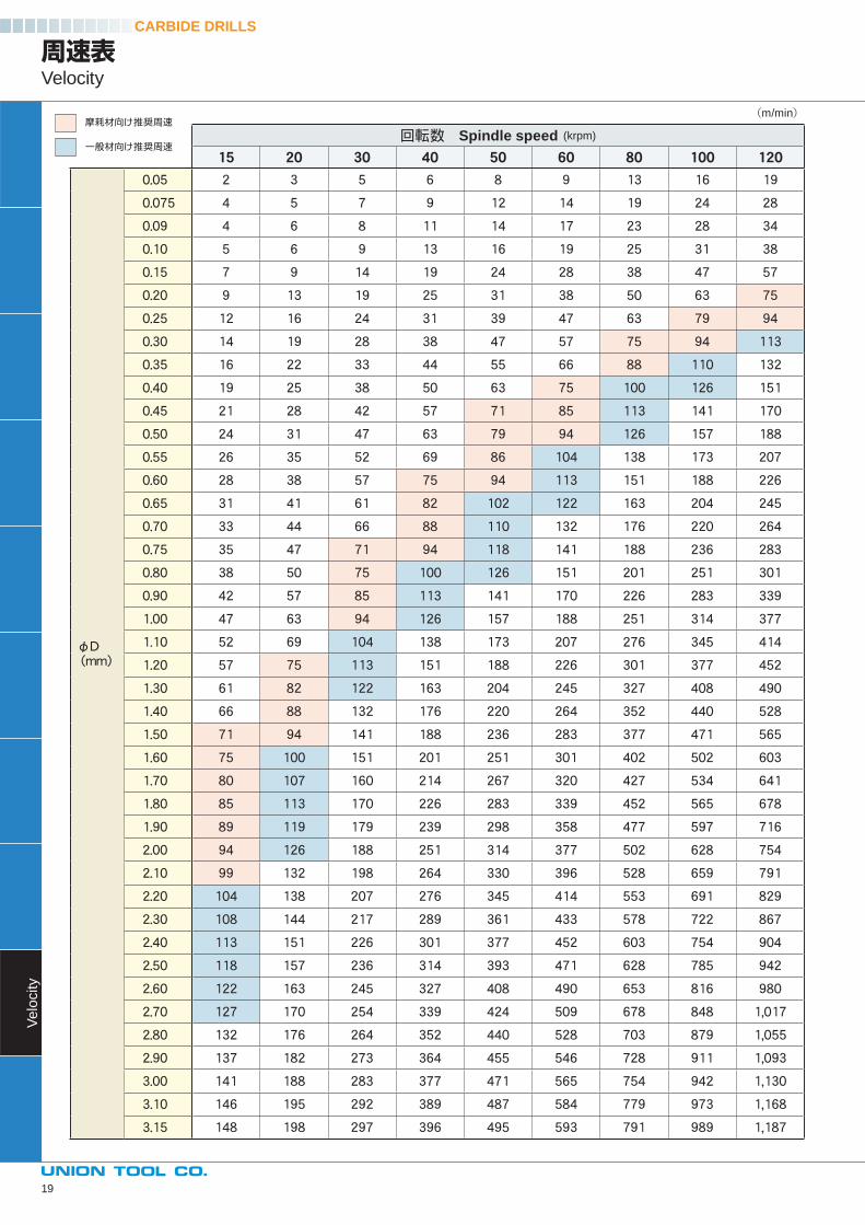
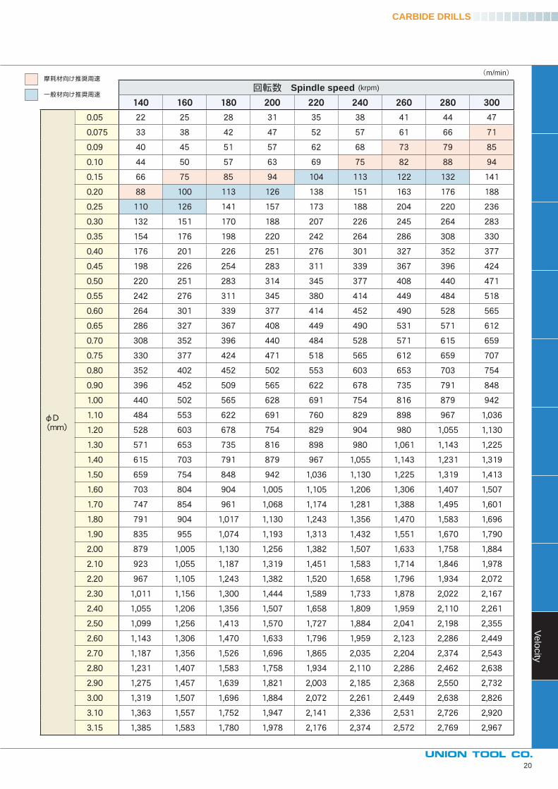
周速表Velocity
(m/min)
CARBIDE DRILLS
摩耗材向け推奨周速
一般材向け推奨周速
19
Ve
locity
回転数 Spindle speed (krpm)
20
(m/min)
CARBIDE DRILLS
摩耗材向け推奨周速
一般材向け推奨周速
ULF coatedULF coated
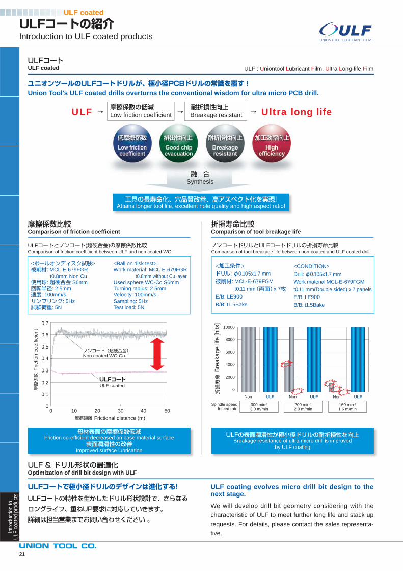
ULFコートとノンコート(超硬合金)の摩擦係数比較Comparison of friction coeffi cient between ULF and non coated WC.
ノンコートドリルとULFコートドリルの折損寿命比較Comparison of tool breakage life between non-coated and ULF coated drill.
<ボールオンディスク試験>
被削材: MCL-E-679FGR
t0.8mm Non Cu
使用球: 超硬合金 S6mm
回転半径: 2.5mm
速度: 100mm/s
サンプリング: 5Hz
試験荷重: 5N
<加工条件>ドリル: φ0.105x1.7 mm
被削材: MCL-E-679FGM
t0.11 mm(両面)x 7枚E/B: LE900
B/B: t1.5Bake
0
0.1
0.2
0.3
0.4
0.5
0.6
0.7
0 10 20 30 40 50
Frictio
n c
oe
ffic
ien
t
Frictional distance (m)
摩擦係数
摩擦距離
ノンコート(超硬合金)
ULFコート
Non coated WC-Co
ULF coated
10000
8000
6000
4000
2000
0
Non
300 min-1
3.0 m/min200 min-1
2.0 m/min160 min-1
1.6 m/min
ULF ULF ULFNon Non
Spindle speedInfeed rate
折損寿命
Bre
aka
ge
life
[h
its]
<Ball on disk test>
Work material: MCL-E-679FGR
t0.8mm without Cu layer
Used sphere WC-Co S6mm
Turning radius: 2.5mm
Velocity: 100mm/s
Sampling: 5Hz
Test load: 5N
<CONDITION>
Drill: φ0.105x1.7 mm
Work material:MCL-E-679FGM
t0.11 mm(Double sided) x 7 panels
E/B: LE900
B/B: t1.5Bake
Intr
oduct
ion to
UL
F c
oa
ted
pro
du
cts
ULFコートの紹介Introduction to ULF coated products
ULFコートULF coated
ユニオンツールのULFコートドリルが、極小径PCBドリルの常識を覆す!Union Tool's ULF coated drills overturns the conventional wisdom for ultra micro PCB drill.
ULF : Uniontool Lubricant Film, Ultra Long-life Film
融 合Synthesis
ULF → 摩擦係数の低減 → 耐折損性向上
→ Ultra long life Low friction coeffi cient Breakage resistant
工具の長寿命化、穴品質改善、高アスペクト化を実現!Attains longer tool life, excellent hole quality and high aspect ratio!
摩擦係数比較Comparison of friction coeffi cient
折損寿命比較Comparison of tool breakage life
ULF & ドリル形状の最適化Optimization of drill bit design with ULF
ULFコートで極小径ドリルのデザインは進化する!
ULFコートの特性を生かしたドリル形状設計で、さらなる
ロングライフ、重ねUP要求に対応していきます。
詳細は担当営業までお問い合わせください 。
ULF coating evolves micro drill bit design to the next stage.We will develop drill bit geometry considering with the
characteristic of ULF to meet further long life and stack up
requests. For details, please contact the sales representa-
tive.
母材表面の摩擦係数低減Friction co-effi cient decreased on base material surface
表面潤滑性の改善Improved surface lubrication
ULFの表面潤滑性が極小径ドリルの耐折損性を向上Breakage resistance of ultra micro drill is improved
by ULF coating
21
Diamond coatedDiamond coated
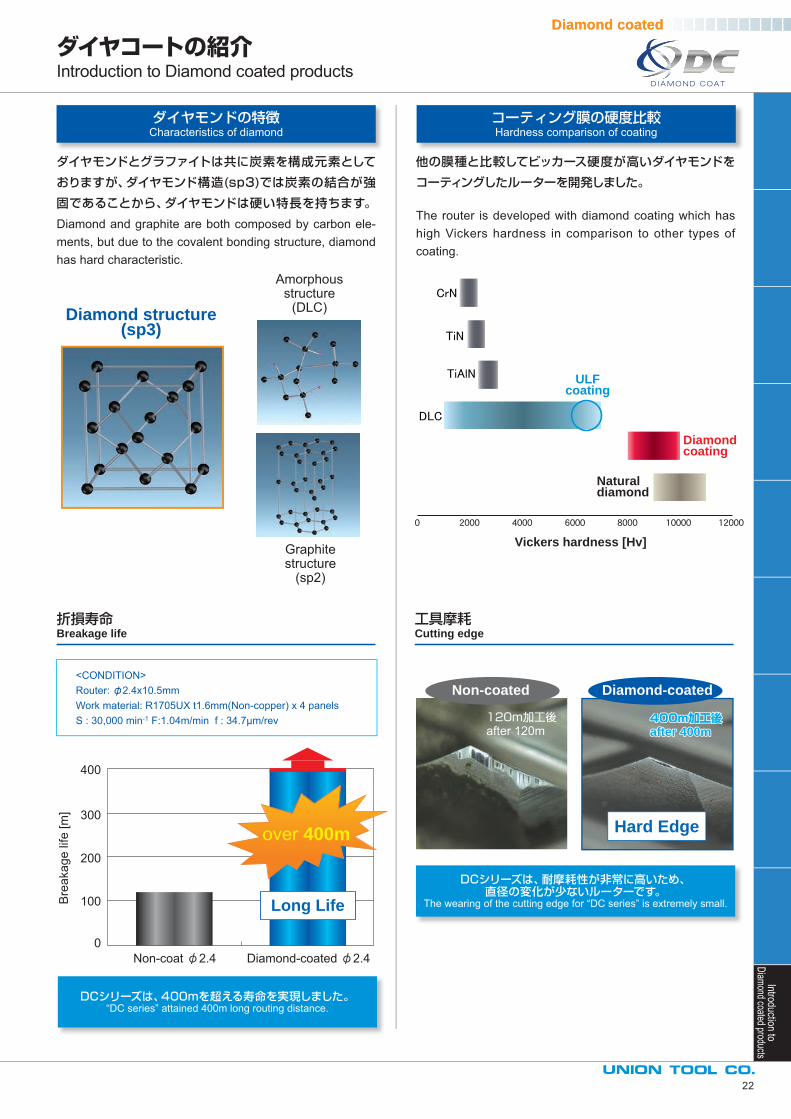
<CONDITION>Router: φ2.4x10.5mmWork material: R1705UX t1.6mm(Non-copper) x 4 panelsS : 30,000 min-1 F:1.04m/min f : 34.7μm/rev
0Non-coat 2.4 Diamond-coated 2.4
100
200
300
400
Bre
akag
e lif
e [m
]
Long Life
over 400m
DCシリーズは、400mを超える寿命を実現しました。“DC series” attained 400m long routing distance.
DCシリーズは、耐摩耗性が非常に高いため、直径の変化が少ないルーターです。
The wearing of the cutting edge for “DC series” is extremely small.
Diamond-coatedNon-coated
Hard Edge
120m加工後after 120m
400m加工後400m加工後after 400mafter 400m400m加工後after 400m
Introduction toDiamond coated products
22
ダイヤコートの紹介Introduction to Diamond coated products
ダイヤモンドの特徴Characteristics of diamond
コーティング膜の硬度比較Hardness comparison of coating
ダイヤモンドとグラファイトは共に炭素を構成元素として
おりますが、ダイヤモンド構造(sp3)では炭素の結合が強
固であることから、ダイヤモンドは硬い特長を持ちます。
Diamond and graphite are both composed by carbon ele-ments, but due to the covalent bonding structure, diamond has hard characteristic.
他の膜種と比較してビッカース硬度が高いダイヤモンドを
コーティングしたルーターを開発しました。
The router is developed with diamond coating which has high Vickers hardness in comparison to other types of coating.
Vickers hardness [Hv]
Naturaldiamond
Diamondcoating
ULFcoating
折損寿命Breakage life
工具摩耗Cutting edge
Diamond structure(sp3)
Amorphousstructure
(DLC)
Graphitestructure
(sp2)
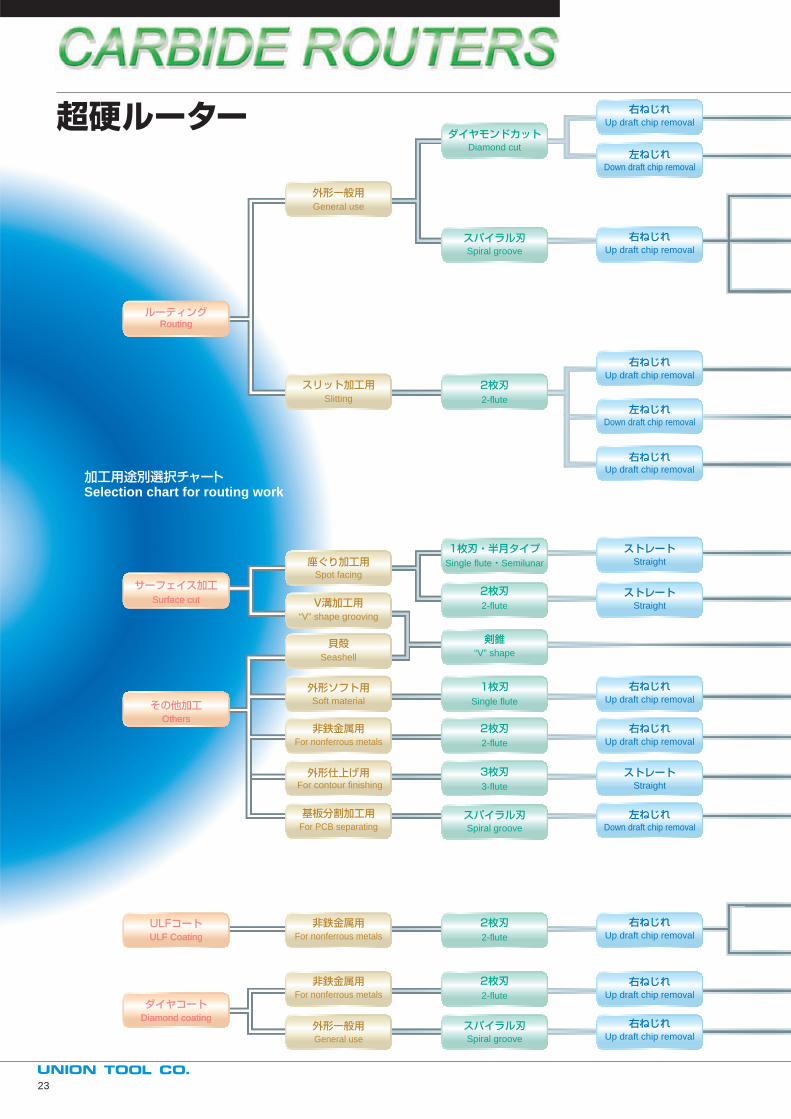
Selection chart for routing work
Up draft chip removal
右ねじれ
ダイヤモンドカット
Up draft chip removal
右ねじれ
Up draft chip removal
右ねじれ
Up draft chip removal
右ねじれ
右ねじれ
Down draft chip removal
左ねじれ2-flute
Diamond cut
外形一般用
ルーティング
その他加工
サーフェイス加工
2枚刃
2-flute
2枚刃
スパイラル刃Spiral groove
General use
スリット加工用Slitting
For nonferrous metals
非鉄金属用
General use
外形一般用
RoutingRouting
OthersOthers
ULFコートULF CoatingULF Coating
ダイヤコートDiamond coatingDiamond coating
Surface cutSurface cut
Up draft chip removal
Down draft chip removal
左ねじれ
Up draft chip removal
右ねじれスパイラル刃Spiral groove
Up draft chip removal
右ねじれ2-flute
2枚刃For nonferrous metals
非鉄金属用
Up draft chip removal
右ねじれ
Up draft chip removal
右ねじれ
Straight
ストレート
Down draft chip removal
左ねじれ
2-flute
2枚刃
3-flute
3枚刃
Single flute
1枚刃
スパイラル刃Spiral groove
Soft material
For contour finishing
For nonferrous metals
外形ソフト用
非鉄金属用
For PCB separating
基板分割加工用
外形仕上げ用
“V” shape
剣錐
V溝加工用“V” shape grooving
貝殻Seashell
Straight
ストレート
Straight
ストレート2-flute
2枚刃
Single flute・Semilunar
1枚刃・半月タイプ座ぐり加工用
Spot facing
超硬ルーター
23
CARBIDE ROUTERS
型 番Model型 番Model
特 徴・用 途Features・use特 徴・用 途Features・use
サイズSizeサイズSize
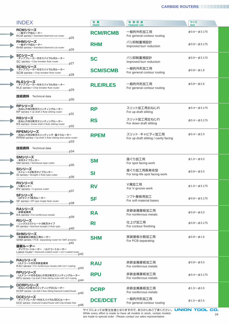
RCMシリーズ・一般ダイヤ目ルーターRCM series • Standard diamond cut router....................................................................p25
RCM/RCMB
RHM
INDEX
RHMシリーズ・一般ダイヤ目ルーターRHM series • Standard diamond cut router....................................................................p26
SCシリーズ・チップブレーカー付きスパイラル刃ルーターSC series • Chip-breaker fl ute router....................................................................p27
RLEシリーズ・チップブレーカー付きスパイラル刃ルーターRLE series • Chip-breaker fl ute router....................................................................p29
RSシリーズ・左ねじれ形2枚刃スリッティングルーターRS series • Down draft 2-fl ute slitting router....................................................................p32
RPEMシリーズ・右ねじれ形2枚刃スリッティング・座ぐりルーターRPEM series • Up draft 2-fl ute slitting and cavity router
....................................................................p33
RPシリーズ・右ねじれ形2枚刃スリッティングルーターRP series • Up draft 2-fl ute slitting router....................................................................p31
SFシリーズ・DPタイプ1枚刃ルーターSF series • DP type single-fl ute router....................................................................p38
SMシリーズ・半月タイプカッターSM series • Semilunar-type cutter....................................................................p35
SIシリーズ・ストレート2枚刃タイプカッターSI series • Straight 2-fl ute type cutter....................................................................p36
RVシリーズ・V溝カッターRV series • V-groove cutter....................................................................p37
RAシリーズ・非鉄金属用RA series • For nonferrous metals....................................................................p39
SHMシリーズ・実装基板分割加工用ルーターSHM series • PCB separating router for SMT prosess
....................................................................p41
RIシリーズ・ニック入りストレート3枚刃タイプRI series • Notched straight 3-fl ute type ....................................................................p40
SC
SCM/SCMB
RA
RI
SHM
RPUシリーズ・ULFコート付き右ねじれ形2枚刃スリッティングルーターRPU series • Up draft 2-fl ute slitting router with ULF coating................................................................................p44
RAUシリーズ・ULFコート付き非鉄金属用RAU series • For nonferrous metals with ULF coating................................................................................p43
SCMシリーズ・チップブレーカー付きスパイラル刃ルーターSCM series • Chip-breaker fl ute router....................................................................p28
RP
RS
SM
SI
RPEM
RAU
RPU
DCRP
DCE/DCETDCEシリーズ・チップブレーカー付きスパイラル刃DCルーターDCE series • Diamond Coated Router with Chip-breaker fl ute................................................................................p46
DCRPシリーズ・右ねじれ2枚刃スリッティングDCルーターDCRP series • Up draft 2-fl ute slitting Diamond Coated Router................................................................................p45
スリット・キャビティ加工用For up draft slitting / cavity facing
φ0.4~φ2.0
φ0.8~φ1.6実装基板分割加工用For PCB separating
24
サイズによっては受注生産となりますので、あらかじめご了承ください。While every effort is made to have all models in stock, certain models
are made to special order - Please contact our sales representative.
一般的外形加工用For general contour routing
φ0.6~φ3.175
φ0.8~φ3.175バリ抑制重視設計Improved burr reduction
バリ抑制重視設計Improved burr reduction
一般的外形加工用For general contour routing
スリット加工用左ねじれFor down draft slitting
スリット加工用右ねじれFor up draft slitting
ソフト基板用加工For soft material bases
座ぐり加工用For spot facing work
座ぐり加工用長寿命型For long-life spot facing work
V溝加工用For V-groove work
非鉄金属基板加工用For nonferrous metals
仕上げ加工用For contour fi nishing
φ0.8~φ3.0
一般的外形加工用For general contour routing
非鉄金属基板加工用For nonferrous metals
RLE/RLES
技術資料 Technical data....................................................................p34
技術資料 Technical data....................................................................p30
φ0.6~φ3.175
φ0.8~φ1.8
φ0.8~φ2.6
φ0.4~φ3.175
φ0.4~φ3.175
φ1.0~φ3.0
φ0.8~φ3.0
φ0.8~φ3.175
φ1.0~φ3.175
φ0.8~φ3.175
RV
SF
非鉄金属基板加工用For nonferrous metals
非鉄金属基板加工用For nonferrous metals
一般的外形加工用For general contour routing
φ0.8~φ3.0
φ0.4~φ3.175
φ1.5~φ2.0
φ1.5~φ2.5
最新ルーター・ダイヤコートルーター ・ULFコートルーターLatest router • Diamond-coated router • ULF-coated router................................................................................p42
CARBIDE ROUTERS
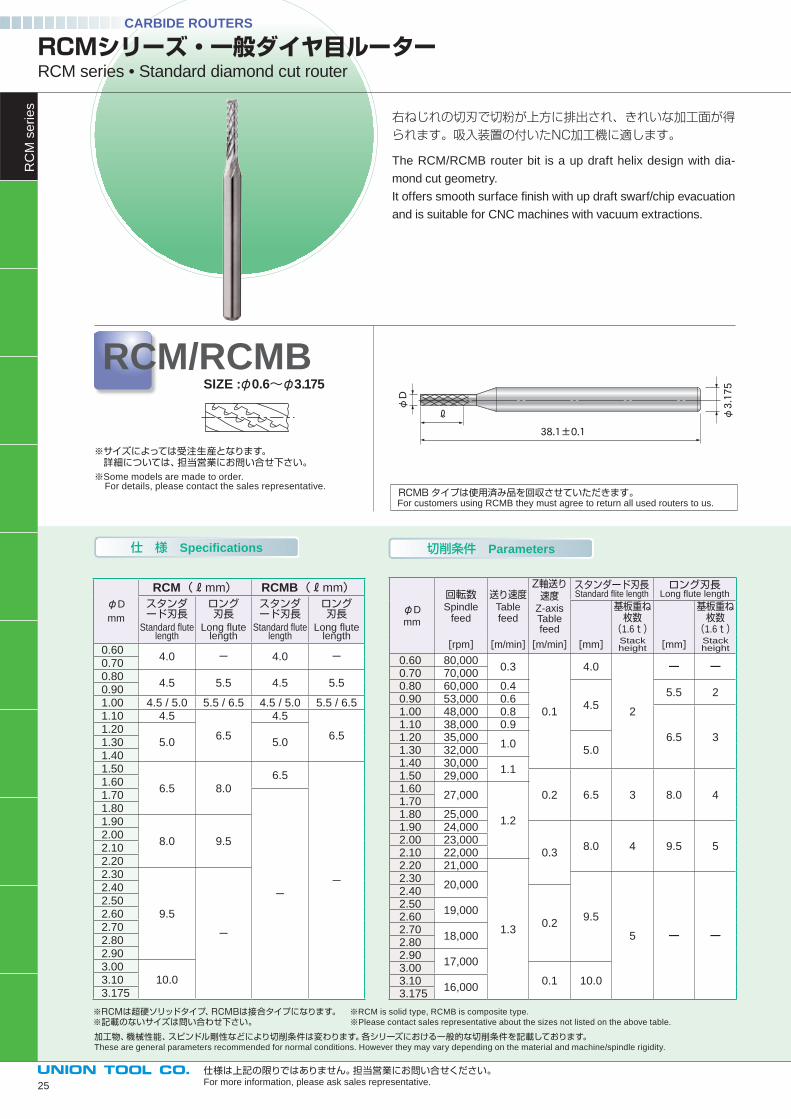
右ねじれの切刃で切粉が上方に排出され、きれいな加工面が得られます。吸入装置の付いたNC加工機に適します。
The RCM/RCMB router bit is a up draft helix design with dia-
mond cut geometry.
It offers smooth surface fi nish with up draft swarf/chip evacuation
and is suitable for CNC machines with vacuum extractions.
φD
φ3.175
38.1±0.1
ℓ
仕 様 Specifications
φD
mm
回転数Spindle
feed
送り速度Table feed
Z軸送り速度
Z-axisTable feed
スタンダード刃長Standard fl ite length
ロング刃長Long fl ute length
基板重ね枚数
(1.6t)
基板重ね枚数
(1.6t)[rpm] [m/min] [m/min] [mm] Stack
height [mm] Stack height
0.60 80,0000.3
0.1
4.0
2
ー ー0.70 70,0000.80 60,000 0.4
4.55.5 2
0.90 53,000 0.61.00 48,000 0.8
6.5 31.10 38,000 0.91.20 35,000
1.05.01.30 32,000
1.40 30,0001.1
1.50 29,000
0.2 6.5 3 8.0 41.60
27,000
1.2
1.701.80 25,0001.90 24,000
0.38.0 4 9.5 5
2.00 23,0002.10 22,0002.20 21,000
1.3
2.3020,000
9.5
5 ー ー
2.40
0.2
2.5019,000
2.602.70
18,0002.802.90
17,0003.00
0.1 10.03.1016,000
3.175
RCMシリーズ・一般ダイヤ目ルーターRCM series • Standard diamond cut router
RCM/RCMB
※サイズによっては受注生産となります。 詳細については、担当営業にお問い合せ下さい。※Some models are made to order. For details, please contact the sales representative.
仕様は上記の限りではありません。担当営業にお問い合せください。For more information, please ask sales representative.
加工物、機械性能、スピンドル剛性などにより切削条件は変わります。各シリーズにおける一般的な切削条件を記載しております。These are general parameters recommended for normal conditions. However they may vary depending on the material and machine/spindle rigidity.
SIZE :φ0.6~φ3.175
※RCMは超硬ソリッドタイプ、RCMBは接合タイプになります。 ※RCM is solid type, RCMB is composite type. ※記載のないサイズは問い合わせ下さい。 ※Please contact sales representative about the sizes not listed on the above table.
切削条件 Parameters
RC
M s
erie
s
φD
mm
RCM mm RCMB mm
スタンダード刃長
Standard fl ute length
ロング刃長
Long fl ute length
スタンダード刃長
Standard fl ute length
ロング刃長
Long fl ute length
0.60 4.0 - 4.0 -
0.70 0.80
4.5 5.5 4.5 5.50.90 1.00 4.5 / 5.0 5.5 / 6.5 4.5 / 5.0 5.5 / 6.51.10 4.5
6.5
4.5
6.51.20
5.0 5.01.30 1.40 1.50
6.5 8.06.5
-
1.60 1.70
-
1.80 1.90
8.0 9.52.00 2.10 2.20 2.30
9.5
-
2.40 2.50 2.60 2.70 2.80 2.90 3.00
10.03.10 3.175
RCMBタイプは使用済み品を回収させていただきます。 For customers using RCMB they must agree to return all used routers to us.
25
仕 様 Specifications
CARBIDE ROUTERS
26
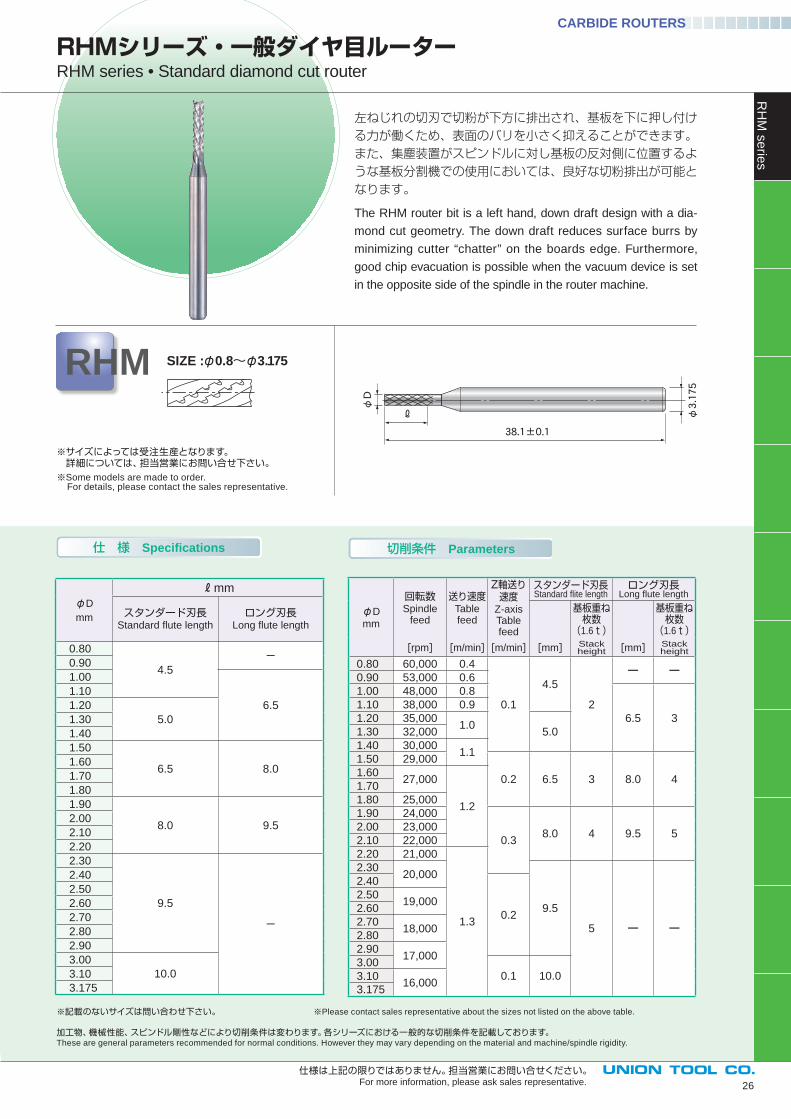
左ねじれの切刃で切粉が下方に排出され、基板を下に押し付ける力が働くため、表面のバリを小さく抑えることができます。また、集塵装置がスピンドルに対し基板の反対側に位置するような基板分割機での使用においては、良好な切粉排出が可能となります。
The RHM router bit is a left hand, down draft design with a dia-
mond cut geometry. The down draft reduces surface burrs by
minimizing cutter “chatter” on the boards edge. Furthermore,
good chip evacuation is possible when the vacuum device is set
in the opposite side of the spindle in the router machine.
RHMシリーズ・一般ダイヤ目ルーターRHM series • Standard diamond cut router
φD
φ3.175
38.1±0.1
ℓ
RHM SIZE :φ0.8~φ3.175
※サイズによっては受注生産となります。 詳細については、担当営業にお問い合せ下さい。※Some models are made to order. For details, please contact the sales representative.
φD
mm
mm
スタンダード刃長Standard fl ute length
ロング刃長Long fl ute length
0.80
4.5
-0.90
1.00
6.5
1.10
1.20
5.01.30
1.40
1.50
6.5 8.01.60
1.70
1.80
1.90
8.0 9.52.00
2.10
2.20
2.30
9.5
-
2.40
2.50
2.60
2.70
2.80
2.90
3.00
10.03.10
3.175
切削条件 Parameters
仕様は上記の限りではありません。担当営業にお問い合せください。For more information, please ask sales representative.
RH
M s
erie
s
※記載のないサイズは問い合わせ下さい。 ※Please contact sales representative about the sizes not listed on the above table.
加工物、機械性能、スピンドル剛性などにより切削条件は変わります。各シリーズにおける一般的な切削条件を記載しております。These are general parameters recommended for normal conditions. However they may vary depending on the material and machine/spindle rigidity.
φD
mm
回転数Spindle
feed
送り速度Table feed
Z軸送り速度
Z-axisTable feed
スタンダード刃長Standard fl ite length
ロング刃長Long fl ute length
基板重ね枚数
(1.6t)
基板重ね枚数
(1.6t)
[rpm] [m/min] [m/min] [mm] Stack height [mm] Stack
height
0.80 60,000 0.4
0.1
4.5
2
ー ー0.90 53,000 0.6
1.00 48,000 0.8
6.5 3
1.10 38,000 0.9
1.20 35,0001.0
5.01.30 32,000
1.40 30,0001.1
1.50 29,000
0.2 6.5 3 8.0 41.60
27,000
1.2
1.70
1.80 25,000
1.90 24,000
0.38.0 4 9.5 5
2.00 23,000
2.10 22,000
2.20 21,000
1.3
2.3020,000
9.5
5 ー ー
2.40
0.2
2.5019,000
2.60
2.7018,000
2.80
2.9017,000
3.00
0.1 10.03.1016,000
3.175
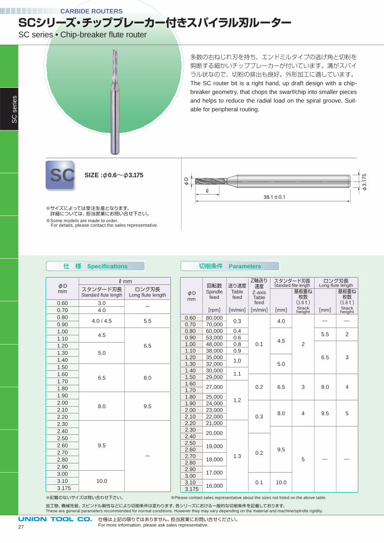
多数の右ねじれ刃を持ち、エンドミルタイプの逃げ角と切粉を剪断する細かいチップブレーカーが付いています。溝がスパイラル状なので、切粉の排出も良好。外形加工に適しています。The SC router bit is a right hand, up draft design with a chip-
breaker geometry, that chops the swarf/chip into smaller pieces
and helps to reduce the radial load on the spiral groove. Suit-
able for peripheral routing.
SCシリーズ・チップブレーカー付きスパイラル刃ルーターSC series • Chip-breaker fl ute router
SC SIZE :φ0.6~φ3.175φD
φ3.175
38.1±0.1ℓ
※サイズによっては受注生産となります。 詳細については、担当営業にお問い合せ下さい。※Some models are made to order. For details, please contact the sales representative.
仕様は上記の限りではありません。担当営業にお問い合せください。For more information, please ask sales representative.
仕 様 Specifications
※記載のないサイズは問い合わせ下さい。 ※Please contact sales representative about the sizes not listed on the above table.
加工物、機械性能、スピンドル剛性などにより切削条件は変わります。各シリーズにおける一般的な切削条件を記載しております。These are general parameters recommended for normal conditions. However they may vary depending on the material and machine/spindle rigidity.
φDmm
mm
スタンダード刃長Standard fl ute length
ロング刃長Long fl ute length
0.60 3.0-
0.70 4.0
0.804.0 / 4.5 5.5
0.90
1.004.5
6.5
1.10
1.20
5.01.30
1.40
1.50
6.5 8.01.60
1.70
1.80
1.90
8.0 9.52.00
2.10
2.20
2.30
9.5
-
2.40
2.50
2.60
2.70
2.80
2.90
3.00
10.03.10
3.175
CARBIDE ROUTERS
φD
mm
回転数Spindle
feed
送り速度Table feed
Z軸送り速度
Z-axisTable feed
スタンダード刃長Standard fl ite length
ロング刃長Long fl ute length
基板重ね枚数
(1.6t)
基板重ね枚数
(1.6t)[rpm] [m/min] [m/min] [mm] Stack
height [mm] Stack height
0.60 80,0000.3
0.1
4.0
2
ー ー0.70 70,000
0.80 60,000 0.4
4.5
5.5 20.90 53,000 0.6
1.00 48,000 0.8
6.5 3
1.10 38,000 0.9
1.20 35,0001.0
5.01.30 32,000
1.40 30,0001.1
1.50 29,000
0.2 6.5 3 8.0 41.60
27,000
1.2
1.70
1.80 25,000
1.90 24,000
0.38.0 4 9.5 5
2.00 23,000
2.10 22,000
2.20 21,000
1.3
2.3020,000
9.5
5 ー ー
2.40
0.2
2.5019,000
2.60
2.7018,000
2.80
2.9017,000
3.00
0.1 10.03.1016,000
3.175
SC
se
rie
s
切削条件 Parameters
27
SCM/SCMB
SCMシリーズ・チップブレーカー付きスパイラル刃ルーター SCM series • Chip-breaker fl ute router
加工物、機械性能、スピンドル剛性などにより切削条件は変わります。各シリーズにおける一般的な切削条件を記載しております。These are general parameters recommended for normal conditions. However they may vary depending on the material and machine/spindle rigidity.
CARBIDE ROUTERS
φD
mm
回転数Spindle
feed
送り速度Table feed
Z軸送り速度
Z-axisTable feed
スタンダード刃長Standard fl ite length
ロング刃長Long fl ute length
基板重ね枚数
(1.6t)
基板重ね枚数
(1.6t)[rpm] [m/min] [m/min] [mm] Stack
height [mm] Stack height
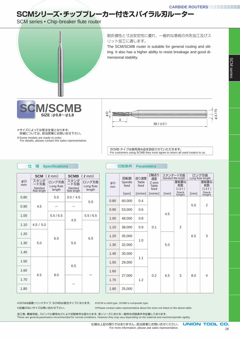
0.80 60,000 0.4
0.1
4.5
2
5.0 2
0.90 53,000 0.6
1.00 48,000 0.8
6.5 3
1.10 38,000 0.9
1.20 35,000
1.0
5.01.30 32,000
1.40 30,000
1.1
1.50 29,000
0.2 6.5 3 8.0 4
1.60
27,000
1.21.70
1.80 25,000
28
仕 様 Specifications
φD
φ3.175
38.1±0.1
ℓ
耐折損性と寸法安定性に優れ、一般的な基板の外形加工及びスリット加工に適します。The SCM/SCMB router is suitable for general routing and slit-
ting. It also has a higher ability to resist breakage and good di-
mensional stability.
SIZE :φ0.8~φ1.8
※サイズによっては受注生産となります。 詳細については、担当営業にお問い合せ下さい。※Some models are made to order. For details, please contact the sales representative.
φDmm
SCM mm SCMB mm
スタンダード刃長Standard
fl ute length
ロング刃長Long fl ute
length
スタンダード刃長Standard
fl ute length
ロング刃長Long fl ute
length
0.80
4.5
5.0 3.0 / 4.5
5.0
0.90 - -
1.00 5.5 / 6.5
4.5
5.5 / 6.5
1.10 4.5 / 5.0
6.5 6.5
1.20
5.0 5.01.30
1.40
1.50
6.5 8.0
6.5
- 1.60
1.70
-1.80
仕様は上記の限りではありません。担当営業にお問い合せください。For more information, please ask sales representative.
SC
M s
erie
s
切削条件 Parameters
※SCMは超硬ソリッドタイプ、SCMBは接合タイプになります。 ※SCM is solid type, SCMB is composite type.
※記載のないサイズは問い合わせ下さい。 ※Please contact sales representative about the sizes not listed on the above table.
SCMBタイプは使用済み品を回収させていただきます。 For customers using SCMB they must agree to return all used routers to us.
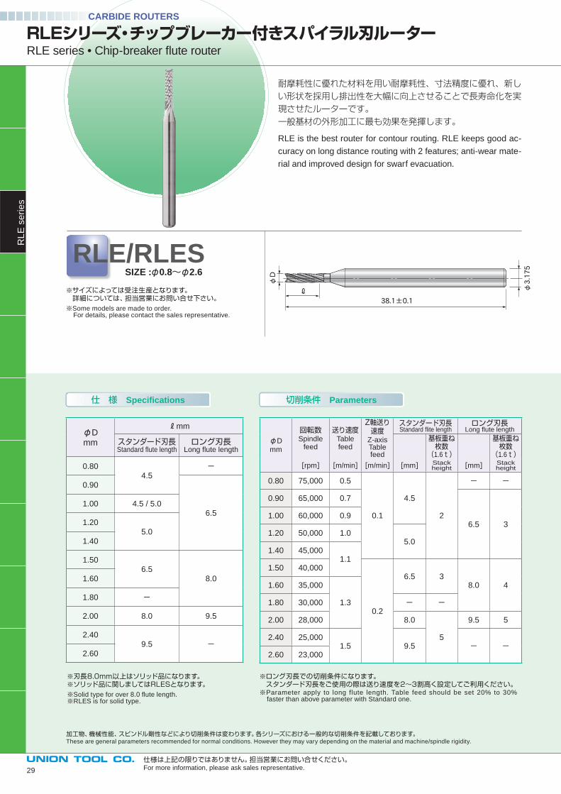
耐摩耗性に優れた材料を用い耐摩耗性、寸法精度に優れ、新しい形状を採用し排出性を大幅に向上させることで長寿命化を実現させたルーターです。一般基材の外形加工に最も効果を発揮します。
RLE is the best router for contour routing. RLE keeps good ac-
curacy on long distance routing with 2 features; anti-wear mate-
rial and improved design for swarf evacuation.
仕 様 Specifications 切削条件 Parameters
RLEシリーズ・チップブレーカー付きスパイラル刃ルーターRLE series • Chip-breaker fl ute router
※サイズによっては受注生産となります。 詳細については、担当営業にお問い合せ下さい。※Some models are made to order. For details, please contact the sales representative.
RLE/RLESSIZE :φ0.8~φ2.6
※刃長8.0mm以上はソリッド品になります。※ソリッド品に関しましてはRLESとなります。※Solid type for over 8.0 fl ute length.※RLES is for solid type.
※ロング刃長での切削条件になります。 スタンダード刃長をご使用の際は送り速度を2~3割高く設定してご利用ください。※Parameter apply to long flute length. Table feed should be set 20% to 30% faster than above parameter with Standard one.
φD
φ3.175
38.1±0.1
ℓ
仕様は上記の限りではありません。担当営業にお問い合せください。For more information, please ask sales representative.
CARBIDE ROUTERS
φD
mm
回転数Spindle
feed
送り速度Table feed
Z軸送り速度
Z-axisTable feed
スタンダード刃長Standard fl ite length
ロング刃長Long fl ute length
基板重ね枚数
(1.6t)
基板重ね枚数
(1.6t)[rpm] [m/min] [m/min] [mm] Stack
height [mm] Stack height
0.80 75,000 0.5
0.1
4.5
2
- -
0.90 65,000 0.7
6.5 31.00 60,000 0.9
1.20 50,000 1.05.0
1.40 45,0001.1
1.50 40,000
0.2
6.5 38.0 41.60 35,000
1.31.80 30,000 - -
2.00 28,000 8.0
5
9.5 5
2.40 25,0001.5 9.5 - -
2.60 23,000
RL
E s
erie
s
加工物、機械性能、スピンドル剛性などにより切削条件は変わります。各シリーズにおける一般的な切削条件を記載しております。These are general parameters recommended for normal conditions. However they may vary depending on the material and machine/spindle rigidity.
φDmm
mm
スタンダード刃長Standard fl ute length
ロング刃長Long fl ute length
0.804.5
-
0.90
6.51.00 4.5 / 5.0
1.205.0
1.40
1.506.5
8.01.60
1.80 -
2.00 8.0 9.5
2.409.5 -
2.60
29
技術資料Technical data
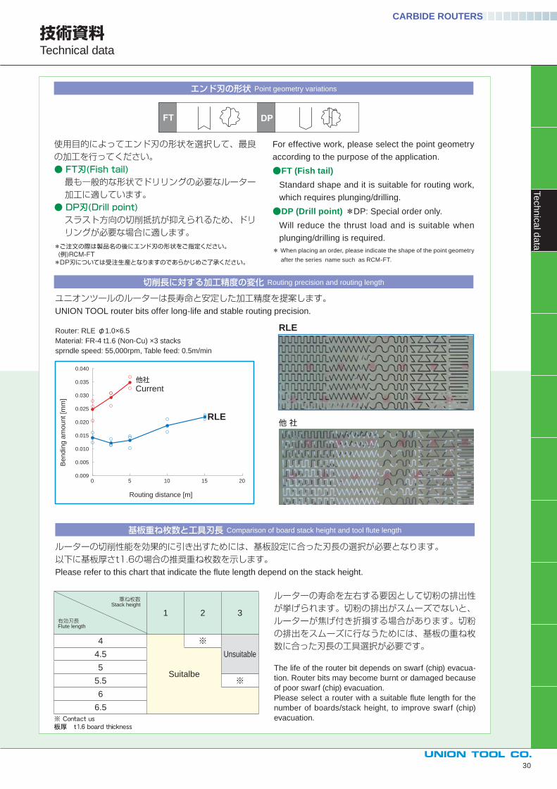
切削長に対する加工精度の変化 Routing precision and routing length
基板重ね枚数と工具刃長 Comparison of board stack height and tool fl ute length
ユニオンツールのルーターは長寿命と安定した加工精度を提案します。UNION TOOL router bits offer long-life and stable routing precision.
ルーターの切削性能を効果的に引き出すためには、基板設定に合った刃長の選択が必要となります。以下に基板厚さt1.6の場合の推奨重ね枚数を示します。Please refer to this chart that indicate the fl ute length depend on the stack height.
ルーターの寿命を左右する要因として切粉の排出性が挙げられます。切粉の排出がスムーズでないと、ルーターが焦げ付き折損する場合があります。切粉の排出をスムーズに行なうためには、基板の重ね枚数に合った刃長の工具選択が必要です。
The life of the router bit depends on swarf (chip) evacua-
tion. Router bits may become burnt or damaged because
of poor swarf (chip) evacuation.
Please select a router with a suitable fl ute length for the
number of boards/stack height, to improve swarf (chip)
evacuation.
For effective work, please select the point geometry
according to the purpose of the application.
●FT (Fish tail)Standard shape and it is suitable for routing work,
which requires plunging/drilling.
●DP (Drill point) *DP: Special order only.
Will reduce the thrust load and is suitable when
plunging/drilling is required.
* When placing an order, please indicate the shape of the point geometry
after the series name such as RCM-FT.
エンド刃の形状 Point geometry variations
使用目的によってエンド刃の形状を選択して、最良の加工を行ってください。● FT刃(Fish tail)最も一般的な形状でドリリングの必要なルーター加工に適しています。
● DP刃(Drill point)スラスト方向の切削抵抗が抑えられるため、ドリリングが必要な場合に適します。
*ご注文の際は製品名の後にエンド刃の形状をご指定ください。 (例)RCM-FT*DP刃については受注生産となりますのであらかじめご了承ください。
CARBIDE ROUTERS
1 2 3
4 ※Unsuitable4.5
5Suitalbe
5.5 ※6
6.5
0.005
0.009
0.010
0.015
0.020
0.025
0.030
0.035
0.040
0 5 10 15 20
Bendin
g a
mount [m
m]
Routing distance [m]
RLE
Current他社
Router: RLE φ1.0×6.5
Material: FR-4 t1.6 (Non-Cu) ×3 stacks
sprndle speed: 55,000rpm, Table feed: 0.5m/min
重ね枚数 Stack height
有効刃長 Flute length
RLE
他 社
30
Te
ch
nic
al d
ata
φDmm
mm
スタンダード刃長Standard fl ute length
ロング刃長Long fl ute length
0.40
※0.50
0.60
0.70
0.80
4.5-
0.90
1.00
6.51.10 -1.20
5.01.30 -
1.40
1.50
6.58.0
1.60
1.80
-
2.00
8.02.20
2.40
2.50
3.00 9.5
3.175
仕様は上記の限りではありません。担当営業にお問い合せください。For more information, please ask sales representative.
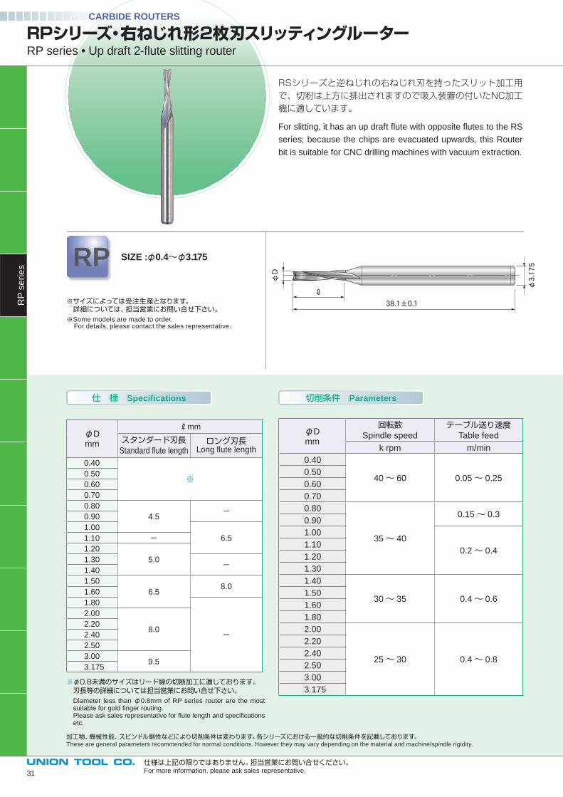
RSシリーズと逆ねじれの右ねじれ刃を持ったスリット加工用で、切粉は上方に排出されますので吸入装置の付いたNC加工機に適しています。
For slitting, it has an up draft fl ute with opposite fl utes to the RS
series; because the chips are evacuated upwards, this Router
bit is suitable for CNC drilling machines with vacuum extraction.
φD
38.1±0.1
ℓ
φ3.175
仕 様 Specifications 切削条件 Parameters
※φ0.8未満のサイズはリード線の切断加工に適しております。 刃長等の詳細については担当営業にお問い合せ下さい。
Diameter less than φ0.8mm of RP series router are the most suitable for gold fi nger routing.Please ask sales representative for fl ute length and specifi cations etc.
φDmm
回転数Spindle speed
テーブル送り速度Table feed
k rpm m/min
0.40
40~ 60 0.05~ 0.250.50
0.60
0.70
0.80
35~ 40
0.15~ 0.30.90
1.00
0.2~ 0.41.10
1.20
1.30
1.40
30~ 35 0.4~ 0.61.50
1.60
1.80
2.00
25~ 30 0.4~ 0.8
2.20
2.40
2.50
3.00
3.175
RPシリーズ・右ねじれ形2枚刃スリッティングルーターRP series • Up draft 2-fl ute slitting router
RP SIZE :φ0.4~φ3.175
※サイズによっては受注生産となります。 詳細については、担当営業にお問い合せ下さい。※Some models are made to order. For details, please contact the sales representative.
加工物、機械性能、スピンドル剛性などにより切削条件は変わります。各シリーズにおける一般的な切削条件を記載しております。These are general parameters recommended for normal conditions. However they may vary depending on the material and machine/spindle rigidity.
RP
se
rie
sCARBIDE ROUTERS
31
32
仕様は上記の限りではありません。担当営業にお問い合せください。For more information, please ask sales representative.
加工物、機械性能、スピンドル剛性などにより切削条件は変わります。各シリーズにおける一般的な切削条件を記載しております。These are general parameters recommended for normal conditions. However they may vary depending on the material and machine/spindle rigidity.
仕 様 Specifications 切削条件 Parameters
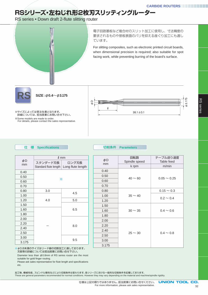
電子回路基板など複合材のスリット加工に使用し、寸法精度の要求されるものや基板表面のバリを抑える座ぐり加工にも適しています。
For slitting composites, such as electronic printed circuit boards,
when dimensional precision is required; also suitable for spot
facing work, while preventing burring of the board’s surface.
φD
φ3.175
38.1±0.1
ℓ
φDmm
mm
スタンダード刃長Standard fl ute length
ロング刃長Long fl ute length
0.40
※0.50
0.60
0.70
0.80 3.04.5
1.00
4.01.20 5.0
1.50
6.51.60
-
1.80
2.00
8.02.20
2.40
2.50
3.009.5
3.175
RSシリーズ・左ねじれ形2枚刃スリッティングルーター RS series • Down draft 2-fl ute slitting router
RS SIZE :φ0.4~φ3.175
※φ0.8未満のサイズはリード線の切断加工に適しております。 刃長等の詳細については担当営業にお問い合せ下さい。
Diameter less than φ0.8mm of RS series router are the most
suitable for gold fi nger routing.
Please ask sales representative for fl ute length and specifi cations
etc.
※サイズによっては受注生産となります。 詳細については、担当営業にお問い合せ下さい。※Some models are made to order. For details, please contact the sales representative.
φDmm
回転数Spindle speed
テーブル送り速度Table feed
k rpm m/min
0.40
40~ 60 0.05~ 0.250.50
0.60
0.70
0.80
35~ 40
0.15~ 0.3
1.000.2~ 0.4
1.20
1.50
30~ 35 0.4~ 0.61.60
1.80
2.00
25~ 30 0.4~ 0.8
2.20
2.40
2.50
3.00
3.175
RS
se
ries
CARBIDE ROUTERS
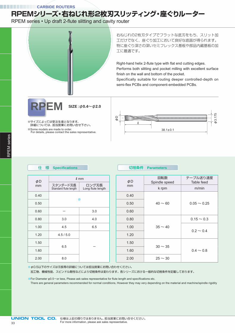
右ねじれの2枚刃タイプでフラットな底刃をもち、スリット加工だけでなく、座ぐり加工において良好な底面が得られます。特に座ぐり深さの深いセミフレックス基板や部品内蔵基板の加工に最適です。
Right-hand helix 2-fl ute type with fl at end cutting edges.Performs both slitting and pocket milling with excellent surface fi nish on the wall and bottom of the pocket. Specifically suitable for routing deeper controlled-depth on semi-fl ex PCBs and component-embedded PCBs.
仕 様 Specifications 切削条件 Parameters
RPEMシリーズ・右ねじれ形2枚刃スリッティング・座ぐりルーターRPEM series • Up draft 2-fl ute slitting and cavity router
※サイズによっては受注生産となります。 詳細については、担当営業にお問い合せ下さい。※Some models are made to order. For details, please contact the sales representative.
RPEM SIZE :φ0.4~φ2.0
※φ0.5以下のサイズは刃長等の詳細については担当営業にお問い合わせください。
加工物、機械性能、スピンドル剛性などにより切削条件は変わります。各シリーズにおける一般的な切削条件を記載しております。
※For Diameter φ0.5-or less, Please ask sales representative for fl ute length and specifi cations etc. There are general parameters recommended for normal conditions, However they may very depending on the material and machine/spindle rigidity
38.1± 0.1
φ3.
175
φD
仕様は上記の限りではありません。担当営業にお問い合せください。For more information, please ask sales representative.
CARBIDE ROUTERSR
PE
M s
erie
s
φDmm
mm
スタンダード刃長Standard fl ute length
ロング刃長Long fl ute length
0.40※
0.50
0.60 - 3.0
0.80 3.0 4.0
1.00 4.5 6.5
1.20 4.5 / 5.0
-1.50
6.51.60
2.00 8.0
φDmm
回転数Spindle speed
テーブル送り速度Table feed
k rpm m/min
0.40
40~ 60 0.05~ 0.250.50
0.60
0.80
35~ 40
0.15~ 0.3
1.000.2~ 0.4
1.20
1.5030~ 35
0.4~ 0.81.60
2.00 25~ 30
33
技術資料Technical data
CARBIDE ROUTERS
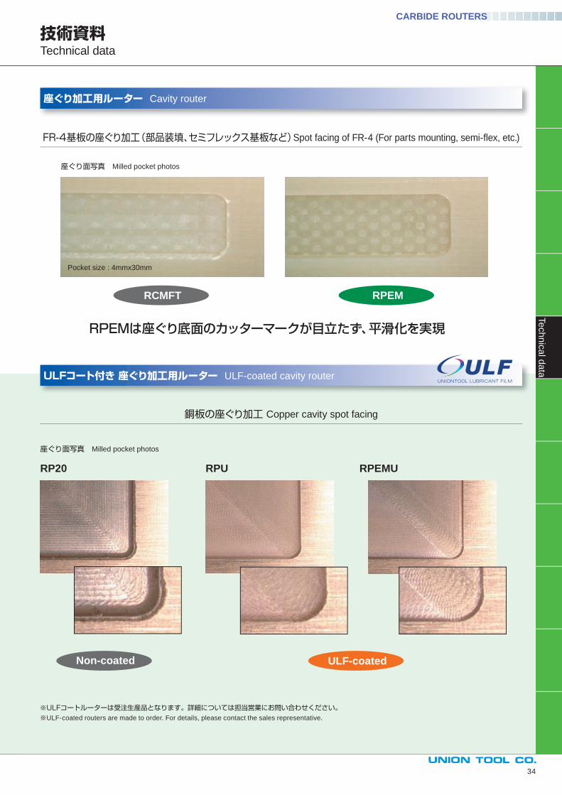
ULFコート付き 座ぐり加工用ルーター ULF-coated cavity router
座ぐり加工用ルーター Cavity router
※ULFコートルーターは受注生産品となります。詳細については担当営業にお問い合わせください。※ULF-coated routers are made to order. For details, please contact the sales representative.
座ぐり面写真 Milled pocket photos
座ぐり面写真 Milled pocket photos
RPEMは座ぐり底面のカッターマークが目立たず、平滑化を実現
Pocket size : 4mmx30mm
FR-4基板の座ぐり加工(部品装填、セミフレックス基板など)Spot facing of FR-4 (For parts mounting, semi-fl ex, etc.)
銅板の座ぐり加工 Copper cavity spot facing
34
Te
ch
nic
al d
ata
RPEM
RPEMURPURP20
ULF-coatedNon-coated
RCMFT
仕 様 Specifications 切削条件 Parameters
CARBIDE ROUTERS
仕様は上記の限りではありません。担当営業にお問い合せください。For more information, please ask sales representative.
φD
38.1±0.1ℓ φ
3.175
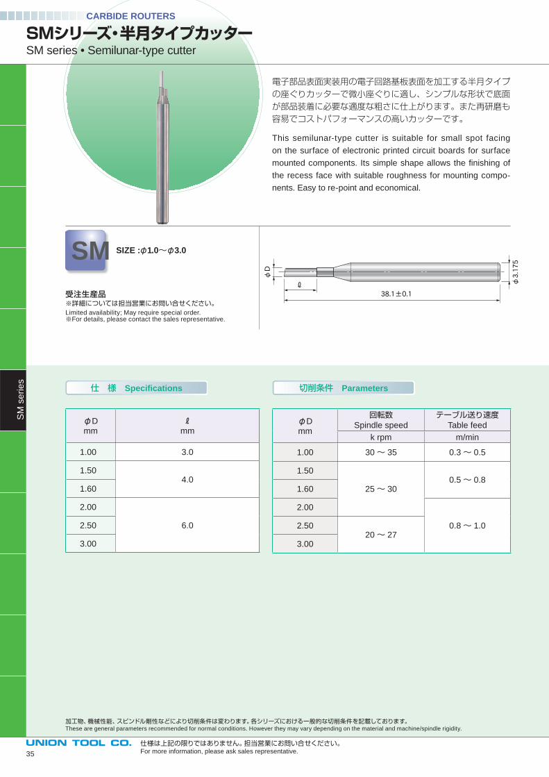
電子部品表面実装用の電子回路基板表面を加工する半月タイプの座ぐりカッターで微小座ぐりに適し、シンプルな形状で底面が部品装着に必要な適度な粗さに仕上がります。また再研磨も容易でコストパフォーマンスの高いカッターです。
This semilunar-type cutter is suitable for small spot facing
on the surface of electronic printed circuit boards for surface
mounted components. Its simple shape allows the fi nishing of
the recess face with suitable roughness for mounting compo-
nents. Easy to re-point and economical.
φDmm mm
1.00 3.0
1.504.0
1.60
2.00
6.02.50
3.00
φDmm
回転数Spindle speed
テーブル送り速度Table feed
k rpm m/min
1.00 30~ 35 0.3~ 0.5
1.50
25~ 300.5~ 0.8
1.60
2.00
0.8~ 1.02.5020~ 27
3.00
SMシリーズ・半月タイプカッターSM series • Semilunar-type cutter
SM SIZE :φ1.0~φ3.0
受注生産品※詳細については担当営業にお問い合せください。Limited availability; May require special order.※For details, please contact the sales representative.
加工物、機械性能、スピンドル剛性などにより切削条件は変わります。各シリーズにおける一般的な切削条件を記載しております。These are general parameters recommended for normal conditions. However they may vary depending on the material and machine/spindle rigidity.
SM
se
rie
s
35
■テクニカルデータ:サーフェイスマウント用座ぐり加工 Technical data : Spot facing work for surface mounting
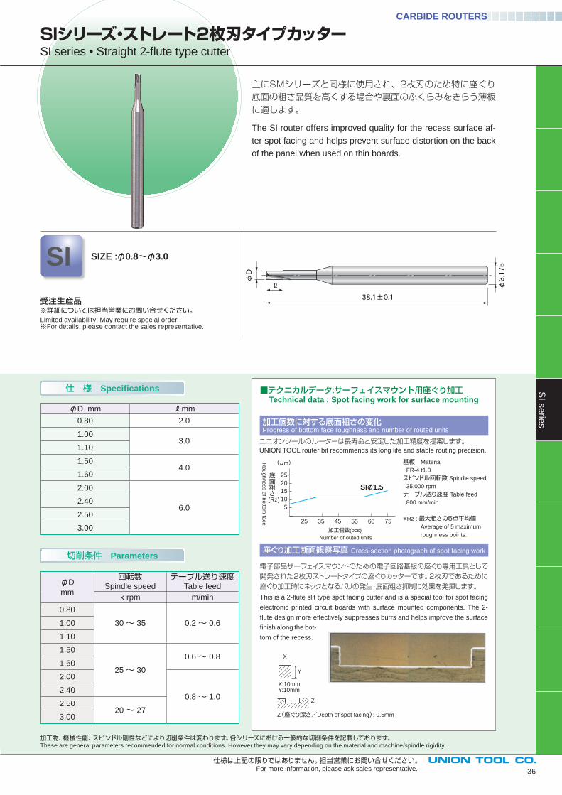
主にSMシリーズと同様に使用され、2枚刃のため特に座ぐり底面の粗さ品質を高くする場合や裏面のふくらみをきらう薄板に適します。
The SI router offers improved quality for the recess surface af-
ter spot facing and helps prevent surface distortion on the back
of the panel when used on thin boards.
φD
38.1±0.1
ℓ φ3.175
仕 様 Specifications
切削条件 Parameters
φD
mm
回転数Spindle speed
テーブル送り速度Table feed
k rpm m/min
0.80
30~ 35 0.2~ 0.61.00
1.10
1.50
25~ 30
0.6~ 0.81.60
2.00
0.8~ 1.02.40
2.5020~ 27
3.00
SIシリーズ・ストレート2枚刃タイプカッターSI series • Straight 2-fl ute type cutter
SI SIZE :φ0.8~φ3.0
受注生産品※詳細については担当営業にお問い合せください。Limited availability; May require special order.※For details, please contact the sales representative.
加工個数に対する底面粗さの変化Progress of bottom face roughness and number of routed units
座ぐり加工断面観察写真 Cross-section photograph of spot facing work
ユニオンツールのルーターは長寿命と安定した加工精度を提案します。UNION TOOL router bit recommends its long life and stable routing precision.
基板 Material
: FR-4 t1.0
スピンドル回転数 Spindle speed
: 35,000 rpm
テーブル送り速度 Table feed
: 800 mm/min
*Rz : 最大粗さの5点平均値 Average of 5 maximum
roughness points.加工個数(pcs)
Number of outed units
25 35 45 55 65 75
25
20
15
10
5
底面粗さ
(Rz)
Ro
ug
hn
ess o
f bo
ttom
face
(μm)
SIφ1.5
電子部品サーフェイスマウントのための電子回路基板の座ぐり専用工具として開発された2枚刃ストレートタイプの座ぐりカッターです。2枚刃であるために座ぐり加工時にネックとなるバリの発生・底面粗さ抑制に効果を発揮します。
This is a 2-flute slit type spot facing cutter and is a special tool for spot facing
electronic printed circuit boards with surface mounted components. The 2-
flute design more effectively suppresses burrs and helps improve the surface
finish along the bot-
tom of the recess.
Z(座ぐり深さ/Depth of spot facing): 0.5mm
X:10mmY:10mm
X
Y
Z
加工物、機械性能、スピンドル剛性などにより切削条件は変わります。各シリーズにおける一般的な切削条件を記載しております。These are general parameters recommended for normal conditions. However they may vary depending on the material and machine/spindle rigidity.
CARBIDE ROUTERS
φD mm mm
0.80 2.0
1.003.0
1.10
1.504.0
1.60
2.00
6.02.40
2.50
3.00
36
仕様は上記の限りではありません。担当営業にお問い合せください。For more information, please ask sales representative.
SI s
erie
s
仕 様 Specifications 切削条件 Parameters
CARBIDE ROUTERS
φDmm
回転数Spindle speed
テーブル送り速度Table feed
k rpm m/min
1.00
30~ 35
0.6~ 0.81.10
1.20
1.30
1.40
0.8~ 1.0
1.50
1.60
2.00
25~ 303.00
3.175
φD
38.1±0.1
φ3.175
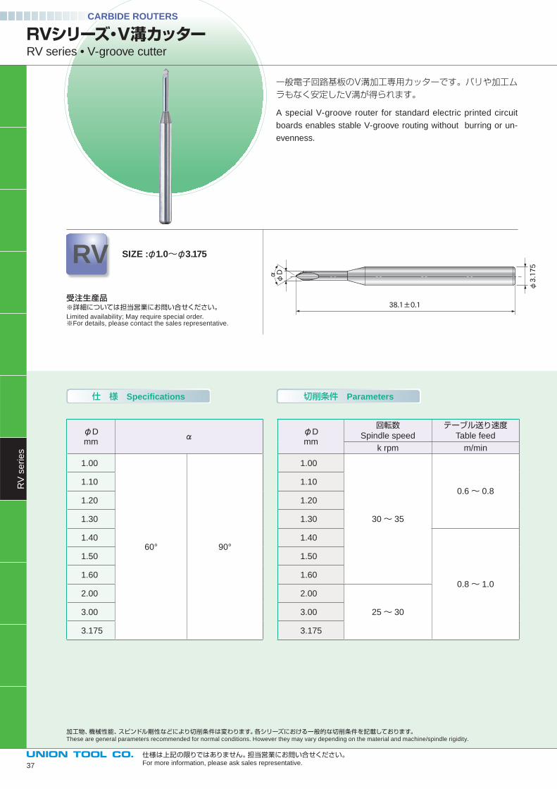
α
φDmm
1.00
60° 90°
1.10
1.20
1.30
1.40
1.50
1.60
2.00
3.00
3.175
受注生産品※詳細については担当営業にお問い合せください。Limited availability; May require special order.※For details, please contact the sales representative.
仕様は上記の限りではありません。担当営業にお問い合せください。For more information, please ask sales representative.
加工物、機械性能、スピンドル剛性などにより切削条件は変わります。各シリーズにおける一般的な切削条件を記載しております。These are general parameters recommended for normal conditions. However they may vary depending on the material and machine/spindle rigidity.
一般電子回路基板のV溝加工専用カッターです。バリや加工ムラもなく安定したV溝が得られます。
A special V-groove router for standard electric printed circuit
boards enables stable V-groove routing without burring or un-
evenness.
RVシリーズ・V溝カッターRV series • V-groove cutter
RV SIZE :φ1.0~φ3.175
RV
se
rie
s
37
φD
38.1±0.1
ℓ
φ3.175
仕 様 Specifications 切削条件 Parameters
φDmm mm
0.804.0
0.90
1.00 4.5
1.20
5.01.30
1.40
1.506.5
1.60
2.008.0
2.40
2.50
9.53.00
3.175
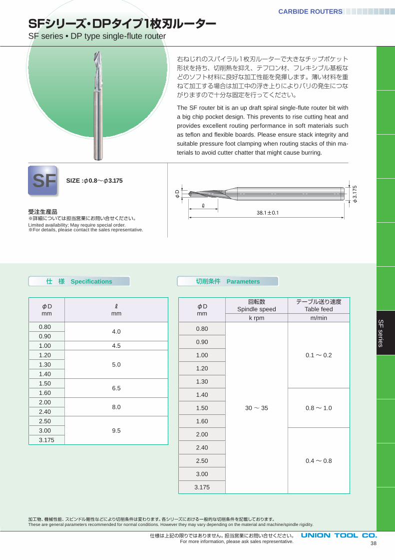
右ねじれのスパイラル1枚刃ルーターで大きなチップポケット形状を持ち、切削熱を抑え、テフロン材、フレキシブル基板などのソフト材料に良好な加工性能を発揮します。薄い材料を重ねて加工する場合は加工中の浮き上りによりバリの発生につながりますので十分な固定を行ってください。
The SF router bit is an up draft spiral single-fl ute router bit with
a big chip pocket design. This prevents to rise cutting heat and
provides excellent routing performance in soft materials such
as tefl on and fl exible boards. Please ensure stack integrity and
suitable pressure foot clamping when routing stacks of thin ma-
terials to avoid cutter chatter that might cause burring.
受注生産品※詳細については担当営業にお問い合せください。Limited availability; May require special order.※For details, please contact the sales representative.
加工物、機械性能、スピンドル剛性などにより切削条件は変わります。各シリーズにおける一般的な切削条件を記載しております。These are general parameters recommended for normal conditions. However they may vary depending on the material and machine/spindle rigidity.
SFシリーズ・DPタイプ1枚刃ルーターSF series • DP type single-fl ute router
SF SIZE :φ0.8~φ3.175
CARBIDE ROUTERS
φDmm
回転数Spindle speed
テーブル送り速度Table feed
k rpm m/min
0.80
30~ 35
0.1~ 0.2
0.90
1.00
1.20
1.30
1.40
0.8~ 1.01.50
1.60
2.00
0.4~ 0.8
2.40
2.50
3.00
3.175
38
仕様は上記の限りではありません。担当営業にお問い合せください。For more information, please ask sales representative.
SF
se
ries
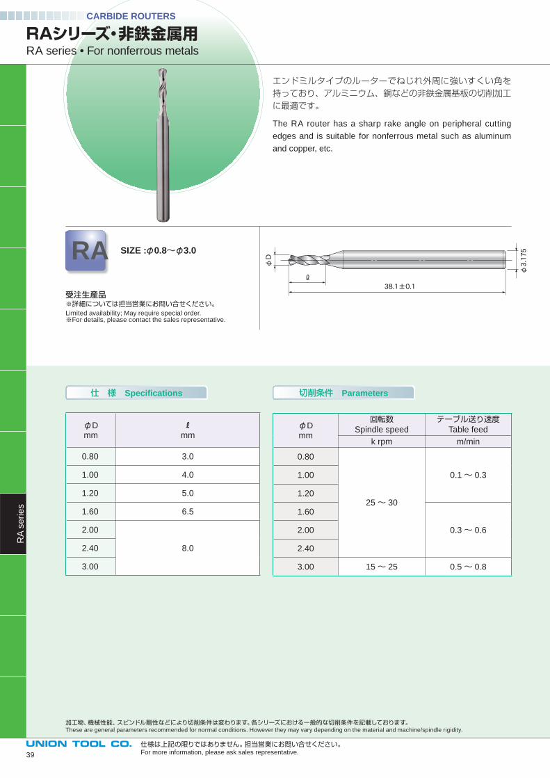
CARBIDE ROUTERS
仕様は上記の限りではありません。担当営業にお問い合せください。For more information, please ask sales representative.
エンドミルタイプのルーターでねじれ外周に強いすくい角を持っており、アルミニウム、銅などの非鉄金属基板の切削加工に最適です。
The RA router has a sharp rake angle on peripheral cutting
edges and is suitable for nonferrous metal such as aluminum
and copper, etc.
φD
ℓ38.1±0.1
φ3.175
仕 様 Specifications 切削条件 Parameters
φDmm mm
0.80 3.0
1.00 4.0
1.20 5.0
1.60 6.5
2.00
8.02.40
3.00
φDmm
回転数Spindle speed
テーブル送り速度Table feed
k rpm m/min
0.80
25~ 30
0.1~ 0.31.00
1.20
1.60
0.3~ 0.62.00
2.40
3.00 15~ 25 0.5~ 0.8
RAシリーズ・非鉄金属用RA series • For nonferrous metals
RA SIZE :φ0.8~φ3.0
受注生産品※詳細については担当営業にお問い合せください。Limited availability; May require special order.※For details, please contact the sales representative.
加工物、機械性能、スピンドル剛性などにより切削条件は変わります。各シリーズにおける一般的な切削条件を記載しております。These are general parameters recommended for normal conditions. However they may vary depending on the material and machine/spindle rigidity.
RA
se
rie
s
39
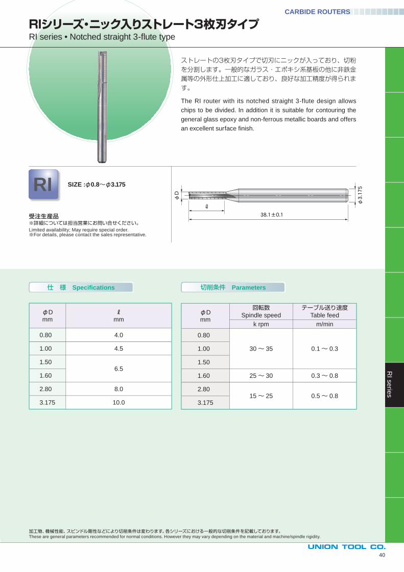
仕 様 Specifications 切削条件 Parameters
ストレートの3枚刃タイプで切刃にニックが入っており、切粉を分割します。一般的なガラス・エポキシ系基板の他に非鉄金属等の外形仕上加工に適しており、良好な加工精度が得られます。
The RI router with its notched straight 3-flute design allows
chips to be divided. In addition it is suitable for contouring the
general glass epoxy and non-ferrous metallic boards and offers
an excellent surface fi nish.
φD
ℓ
38.1±0.1
φ3.175
φDmm mm
0.80 4.0
1.00 4.5
1.506.5
1.60
2.80 8.0
3.175 10.0
φDmm
回転数Spindle speed
テーブル送り速度Table feed
k rpm m/min
0.80
30~ 35 0.1~ 0.31.00
1.50
1.60 25~ 30 0.3~ 0.8
2.8015~ 25 0.5~ 0.8
3.175
受注生産品※詳細については担当営業にお問い合せください。Limited availability; May require special order.※For details, please contact the sales representative.
RIシリーズ・ニック入りストレート3枚刃タイプRI series • Notched straight 3-fl ute type
RI SIZE :φ0.8~φ3.175
RI s
erie
s
40
加工物、機械性能、スピンドル剛性などにより切削条件は変わります。各シリーズにおける一般的な切削条件を記載しております。These are general parameters recommended for normal conditions. However they may vary depending on the material and machine/spindle rigidity.
CARBIDE ROUTERS
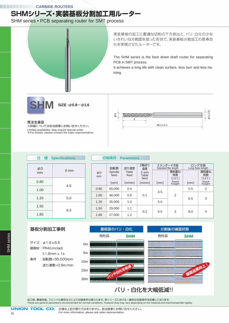
実装基板の加工に最適な切粉の下方排出と、バリ・白化の少ないきれいな分割面を狙った形状で、実装基板分割加工の長寿命化を実現させたルーターです。
The SHM series is the best down draft router for separating
PCB in SMT process.
It achieves a long life with clean surface, less burr and less ha-
loing.
38.1± 0.1
φ3
.17
5
φD
SHMシリーズ・実装基板分割加工用ルーターSHM series • PCB separating router for SMT process
SHM SIZE :φ0.8~φ1.6
受注生産品※詳細については担当営業にお問い合せください。Limited availability; May require special order.※For details, please contact the sales representative.
加工物、機械性能、スピンドル剛性などにより切削条件は変わります。各シリーズにおける一般的な切削条件を記載しております。These are general parameters recommended for normal conditions. However they may vary depending on the material and machine/spindle rigidity.
CARBIDE ROUTERS
φD
mm
回転数Spindle
feed
送り速度Table feed
Z軸送り速度
Z-axisTable feed
スタンダード刃長Standard fl ite length
ロング刃長Long fl ute length
基板重ね枚数
(1.6t)
基板重ね枚数
(1.6t)[rpm] [m/min] [m/min] [mm] Stack
height [mm] Stack height
0.80 60,000 0.4
0.14.5
2
5.5 2
1.00 48,000 0.86.5 3
1.20 35,000 1.0 5.0
1.50 29,000 1.10.2 6.5 3 8.0 4
1.60 27,000 1.2
サイズ:φ1.6x6.5
被削材:FR4(Unclad)
t:1.6mm x 1s
条件 :回転数=35,000rpm
送り速度=0.9m/min
基板面のバリ・白化 分割後の端面状態
他社品 他社品SHM SHM
バリ・白化を大幅低減!!
基板分割加工事例
0m
5m
10m
15m
30m バリや白化を低減!
端面品質向上!
φDmm
mm
0.804.5
1.00
1.20 5.0
1.506.5
1.60
仕 様 Specifications 切削条件 Parameters
仕様は上記の限りではありません。担当営業にお問い合せください。For more information, please ask sales representative.
SH
M s
erie
s
41
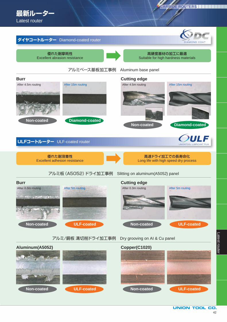
最新ルーターLatest router
優れた耐摩耗性Excellent abrasion resistance
優れた耐溶着性Excellent adhesion resistance
高硬度基材の加工に最適Suitable for high hardness materials
高速ドライ加工での長寿命化Long life with high speed dry process
アルミベース基板加工事例 Aluminum base panel
アルミ板(A5052)ドライ加工事例 Slitting on aluminum(A5052) panel
アルミ/銅板 溝切削ドライ加工事例 Dry grooving on AI & Cu panel
Burr
Burr
Aluminum(A5052)
Cutting edge
Copper(C1020)
Cutting edge
ダイヤコートルーター Diamond-coated router
ULFコートルーター ULF-coated router
Diamond-coated
ULF-coated
ULF-coated
ULF-coated
ULF-coated
Diamond-coatedNon-coated
Non-coated
Non-coated
Non-coated
Non-coated
Non-coated
After 4.5m routing
After 0.3m routing
After 4.5m routing
After 0.3m routing
After 15m routing
After 5m routing
After 15m routing
After 5m routing
CARBIDE ROUTERSL
ate
st ro
ute
r
42

仕 様 Specifications 切削条件 Parameters
φDmm
mm
0.80 3.0
1.00 4.0
1.20 5.0
1.60 6.5
2.00
8.02.40
3.00
CARBIDE ROUTERS
仕様は上記の限りではありません。担当営業にお問い合せください。For more information, please ask sales representative.
RAUシリーズ・ULFコート付き非鉄金属用RAU series • For nonferrous metals with ULF coating
アルミニウムや銅など非鉄金属加工に最適なRAシリーズに、自己潤滑性に優れるULFコートを適用しました。アルミや銅など非鉄金属基板加工での切れ刃への溶着を抑え、バリ改善に効果を発揮します。また、先端もドリルに類似した形状となっており、ドリリングの多い加工にも対応できます。
Excellent self-lubricant ULF-coating is applied on RA series, which are suitable for routing nonferrous metals such as alumi-num and copper. RAU series have signifi cant effect on burr improvement, as the ULF-coating can prevent deposition on the fl ute during routing of nonferrous metals such as aluminum and copper. The tip geometry is similar to drill bit, therefore, it is useful on those applications where many drilled holes are needed.
RAU SIZE :φ0.8~φ3.0
φDmm
回転数Spindle speed
テーブル送り速度Table feed
k rpm m/min
0.80
25~ 30
0.1~ 0.31.00
1.20
1.60
0.3~ 0.62.00
2.40
3.00 15~ 25 0.5~ 0.8
φD
ℓ38.1±0.1
φ3.175
受注生産品※サイズによっては受注生産となります。 詳細については、担当営業にお問い合せ下さい。Limited availability; May require special order.※Some models are made to order. For details, please contact the sales representative.
加工物、機械性能、スピンドル剛性などにより切削条件は変わります。各シリーズにおける一般的な切削条件を記載しております。These are general parameters recommended for normal conditions. However they may vary depending on the material and machine/spindle rigidity.
RA
U s
erie
s
43
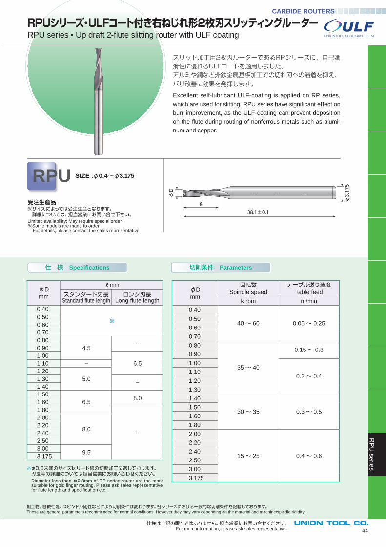
仕 様 Specifications 切削条件 Parameters
CARBIDE ROUTERS
44
仕様は上記の限りではありません。担当営業にお問い合せください。For more information, please ask sales representative.
φD
38.1±0.1
ℓ
φ3.175
スリット加工用2枚刃ルーターであるRPシリーズに、自己潤滑性に優れるULFコートを適用しました。アルミや銅など非鉄金属基板加工での切れ刃への溶着を抑え、バリ改善に効果を発揮します。
Excellent self-lubricant ULF-coating is applied on RP series,
which are used for slitting. RPU series have signifi cant effect on
burr improvement, as the ULF-coating can prevent deposition
on the fl ute during routing of nonferrous metals such as alumi-
num and copper.
φDmm
mm
スタンダード刃長Standard fl ute length
ロング刃長Long fl ute length
0.40
※0.50
0.60
0.70
0.80
4.5−
0.90
1.00
6.51.10 −1.20
5.01.30 −1.40
1.50
6.58.0
1.60
1.80
−
2.00
8.02.20
2.40
2.50
3.009.5
3.175
φDmm
回転数Spindle speed
テーブル送り速度Table feed
k rpm m/min
0.40
40~ 60 0.05~ 0.250.50
0.60
0.70
0.80
35~ 40
0.15~ 0.30.90
1.00
0.2~ 0.41.10
1.20
1.30
1.40
30~ 35 0.3~ 0.51.50
1.60
1.80
2.00
15~ 25 0.4~ 0.6
2.20
2.40
2.50
3.00
3.175
RPUシリーズ・ULFコート付き右ねじれ形2枚刃スリッティングルーターRPU series • Up draft 2-fl ute slitting router with ULF coating
※φ0.8未満のサイズはリード線の切断加工に適しております。 刃長等の詳細については担当営業にお問い合わせください。 Diameter less than φ0.8mm of RP series router are the most
suitable for gold fi nger routing. Please ask sales representative for fl ute length and specifi cation etc.
RPU SIZE :φ0.4~φ3.175
受注生産品※サイズによっては受注生産となります。 詳細については、担当営業にお問い合せ下さい。Limited availability; May require special order.※Some models are made to order. For details, please contact the sales representative.
加工物、機械性能、スピンドル剛性などにより切削条件は変わります。各シリーズにおける一般的な切削条件を記載しております。These are general parameters recommended for normal conditions. However they may vary depending on the material and machine/spindle rigidity.
RP
U s
erie
s
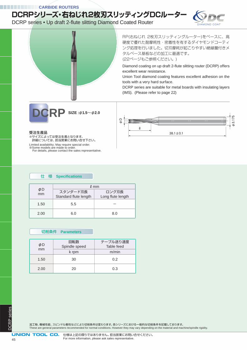
RP(右ねじれ 2枚刃スリッティングルーター)をベースに、高硬度で優れた耐摩耗性・密着性を有するダイヤモンドコーティング処理を行いました。切刃摩耗が起こりやすい絶縁層付きメタルベース基板などの加工に最適です。(22ページもご参照ください。)
Diamond coating on up draft 2-fl ute slitting router (DCRP) offers
excellent wear resistance.
Union Tool diamond coating features excellent adhesion on the
tools with a very hard surface.
DCRP series are suitable for metal boards with insulating layers
(IMS). (Please refer to page 22)
仕 様 Specifications
加工物、機械性能、スピンドル剛性などにより切削条件は変わります。各シリーズにおける一般的な切削条件を記載しております。These are general parameters recommended for normal conditions. However they may vary depending on the material and machine/spindle rigidity.
切削条件 Parameters
CARBIDE ROUTERS
DCRPシリーズ・右ねじれ2枚刃スリッティングDCルーターDCRP series • Up draft 2-fl ute slitting Diamond Coated Router
DCRP SIZE :φ1.5~φ2.0
仕様は上記の限りではありません。担当営業にお問い合せください。For more information, please ask sales representative.
φD
38.1±0.1
ℓ
φ3.175
受注生産品※サイズによっては受注生産となります。 詳細については、担当営業にお問い合せ下さい。Limited availability; May require special order.※Some models are made to order. For details, please contact the sales representative.
φDmm
mm
スタンダード刃長Standard fl ute length
ロング刃長Long fl ute length
1.50 5.5 -
2.00 6.0 8.0
φDmm
回転数Spindle speed
テーブル送り速度Table feed
k rpm m/min
1.50 30 0.2
2.00 20 0.3
DC
RP
se
rie
s
45
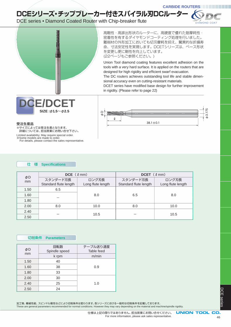
仕 様 Specifications
切削条件 Parameters
高剛性・高排出形状のルーターに、高硬度で優れた耐摩耗性・密着性を有するダイヤモンドコーティング処理を行いました。難削材の外形加工においても切刃摩耗を抑え、驚異的な折損寿命、寸法安定性を実現します。DCETシリーズは、ベース形状を変更し更に剛性を向上しています。(22ページもご参照ください。)
Union Tool diamond coating features excellent adhesion on the
tools with a very hard surface. It is applied on the routers that are
designed for high rigidity and effi cient swarf evacuation.
The DC routers achieves outstanding tool life and stable dimen-
sional accuracy even on cutting-resistant materials.
DCET series have modifi ed base design for further improvement
in rigidity. (Please refer to page 22)
加工物、機械性能、スピンドル剛性などにより切削条件は変わります。各シリーズにおける一般的な切削条件を記載しております。These are general parameters recommended for normal conditions. However they may vary depending on the material and machine/spindle rigidity.
DCEシリーズ・チップブレーカー付きスパイラル刃DCルーターDCE series • Diamond Coated Router with Chip-breaker fl ute
DCE/DCETSIZE :φ1.5~φ2.5
受注生産品※サイズによっては受注生産となります。 詳細については、担当営業にお問い合せ下さい。Limited availability; May require special order.※Some models are made to order. For details, please contact the sales representative.
φD
φ3.175
38.1±0.1
ℓ
CARBIDE ROUTERS
46
φDmm
DCE mm DCET mm
スタンダード刃長Standard fl ute length
ロング刃長Long fl ute length
スタンダード刃長Standard fl ute length
ロング刃長Long fl ute length
1.50 6.5
8.0 6.5 8.01.60-
1.80
2.00 8.0 10.0 8.0 10.0
2.40- 10.5 - 10.5
2.50
φDmm
回転数Spindle speed
テーブル送り速度Table feed
k rpm m/min
1.50 40
0.91.60 38
1.80 33
2.00 30
1.02.40 25
2.50 24
DC
E s
erie
s
仕様は上記の限りではありません。担当営業にお問い合せください。For more information, please ask sales representative.
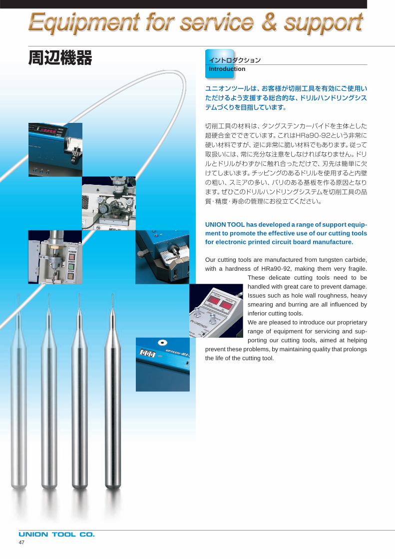
周辺機器 イントロダクションIntroduction
ユニオンツールは、お客様が切削工具を有効にご使用いただけるよう支援する総合的な、ドリルハンドリングシステムづくりを目指しています。
切削工具の材料は、タングステンカーバイドを主体とした
超硬合金でできています。これはHRa90-92という非常に
硬い材料ですが、逆に非常に脆い材料でもあります。従って
取扱いには、常に充分な注意をしなければなりません。ドリ
ルとドリルがわずかに触れ合っただけで、刃先は簡単に欠
けてしまいます。チッピングのあるドリルを使用すると内壁
の粗い、スミアの多い、バリのある基板を作る原因となり
ます。ぜひこのドリルハンドリングシステムを切削工具の品
質・精度・寿命の管理にお役立てください。
UNION TOOL has developed a range of support equip-ment to promote the effective use of our cutting tools for electronic printed circuit board manufacture.
Our cutting tools are manufactured from tungsten carbide,
with a hardness of HRa90-92, making them very fragile.
These delicate cutting tools need to be
handled with great care to prevent damage.
Issues such as hole wall roughness, heavy
smearing and burring are all infl uenced by
inferior cutting tools.
We are pleased to introduce our proprietary
range of equipment for servicing and sup-
porting our cutting tools, aimed at helping
prevent these problems, by maintaining quality that prolongs
the life of the cutting tool.
47
型 番Model型 番Model
INDEX
48
リングセッティングマシン RSM-ARing setting machine
RSM-M1
RSM-M2....................................p49, p50
ドリルポインター MDP-10Miniature drill pointer
MDP-5/5E
....................................p51, p52
ドリル外径測定器 OPTECH-M/MADrill diameter measurement
....................................p53
スピンドル振れ測定器 OPTECH-RI-V/スピンドル振れ&回転数測定器 /V plusSpindle runout indicator
/Spindle runout & speed indicator
....................................p54
デジタルパッサメーター DS-1 Digital passameter
....................................p55
プレッシャ&バキュームチェッカー PV-CHECKERPressure & Vacuum checker
....................................p56
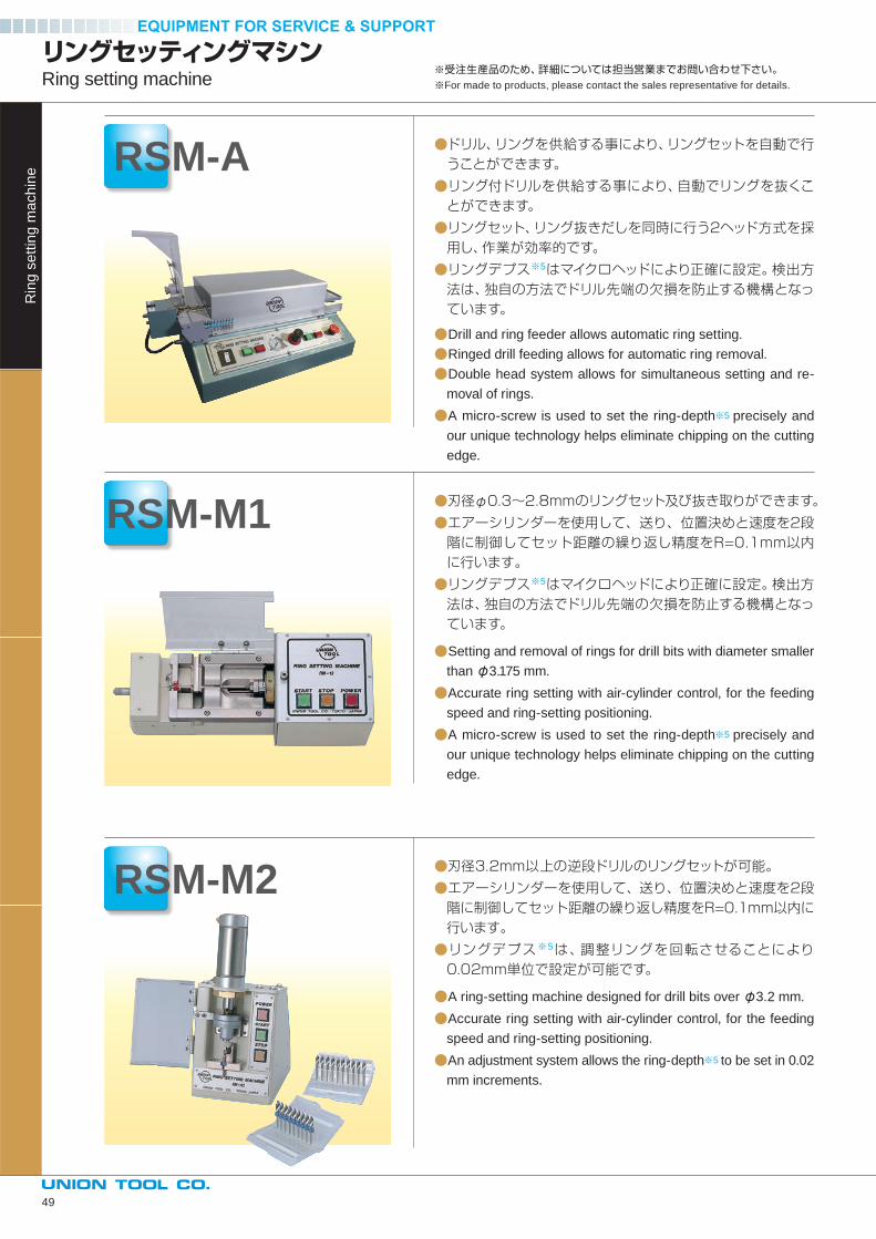
●ドリル、リングを供給する事により、リングセットを自動で行うことができます。
●リング付ドリルを供給する事により、自動でリングを抜くことができます。
●リングセット、リング抜きだしを同時に行う2ヘッド方式を採用し、作業が効率的です。
●リングデプス※5はマイクロヘッドにより正確に設定。検出方法は、独自の方法でドリル先端の欠損を防止する機構となっています。
●Drill and ring feeder allows automatic ring setting.
●Ringed drill feeding allows for automatic ring removal.
●Double head system allows for simultaneous setting and re-
moval of rings.
●A micro-screw is used to set the ring-depth※5 precisely and
our unique technology helps eliminate chipping on the cutting
edge.
●刃径φ0.3~2.8mmのリングセット及び抜き取りができます。
●エアーシリンダーを使用して、送り、位置決めと速度を2段階に制御してセット距離の繰り返し精度をR=0.1mm以内に行います。
●リングデプス※5はマイクロヘッドにより正確に設定。検出方法は、独自の方法でドリル先端の欠損を防止する機構となっています。
●Setting and removal of rings for drill bits with diameter smaller
than φ3.175 mm.
●Accurate ring setting with air-cylinder control, for the feeding
speed and ring-setting positioning.
●A micro-screw is used to set the ring-depth※5 precisely and
our unique technology helps eliminate chipping on the cutting
edge.
●刃径3.2mm以上の逆段ドリルのリングセットが可能。
●エアーシリンダーを使用して、送り、位置決めと速度を2段階に制御してセット距離の繰り返し精度をR=0.1mm以内に行います。
●リングデプス※5は、調整リングを回転させることにより0.02mm単位で設定が可能です。
●A ring-setting machine designed for drill bits over φ3.2 mm.
●Accurate ring setting with air-cylinder control, for the feeding
speed and ring-setting positioning.
●An adjustment system allows the ring-depth※5 to be set in 0.02
mm increments.
リングセッティングマシンRing setting machine
RSM-A
RSM-M1
RSM-M2
Rin
g s
ett
ing
ma
ch
ine
※受注生産品のため、詳細については担当営業までお問い合わせ下さい。※For made to products, please contact the sales representative for details.
49
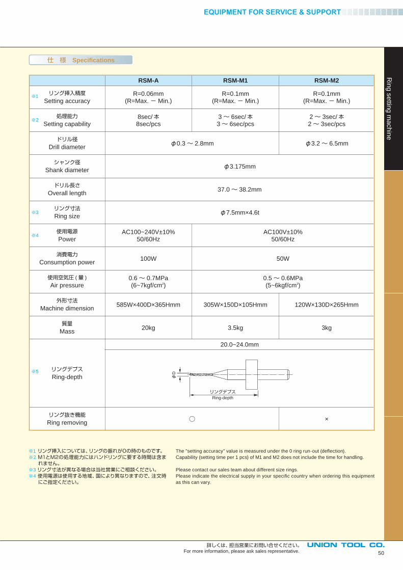
仕 様 Specifications
RSM-A RSM-M1 RSM-M2
リング挿入精度Setting accuracy
R=0.06mm(R=Max.- Min.)
R=0.1mm(R=Max.- Min.)
R=0.1mm(R=Max.- Min.)
処理能力Setting capability
8sec/本8sec/pcs
3~ 6sec/本3~ 6sec/pcs
2~ 3sec/本2~ 3sec/pcs
ドリル径Drill diameter
φ0.3~ 2.8mm φ3.2~ 6.5mm
シャンク径Shank diameter
φ3.175mm
ドリル長さOverall length
37.0~ 38.2mm
リング寸法Ring size
φ7.5mm×4.6t
使用電源Power
AC100~240V±10%50/60Hz
AC100V±10%50/60Hz
消費電力Consumption power
100W 50W
使用空気圧 (量 )
Air pressure0.6~ 0.7MPa(6~7kgf/cm2)
0.5~ 0.6MPa(5~6kgf/cm2)
外形寸法Machine dimension
585W×400D×365Hmm 305W×150D×105Hmm 120W×130D×265Hmm
質量Mass
20kg 3.5kg 3kg
リングデプスRing-depth
20.0~24.0mm
リング抜き機能Ring removing
○ ×
※1 リング挿入については、リングの振れが0の時のものです。※2 M1とM2の処理能力にはハンドリングに要する時間は含ま
れません。※3 リング寸法が異なる場合は当社営業にご相談ください。※4 使用電源は使用する地域、国により異なりますので、注文時にご指定ください。
The "setting accuracy" value is measured under the 0 ring run-out (defl ection).
Capability (setting time per 1 pcs) of M1 and M2 does not include the time for handling.
Please contact our sales team about different size rings.
Please indicate the electrical supply in your specifi c country when ordering this equipment
as this can vary.
φD
リングデプスRing-depth
※1
※2
※3
※4
※5
50
Rin
g s
ettin
g m
ach
ine
詳しくは、担当営業にお問い合せください。For more information, please ask sales representative.
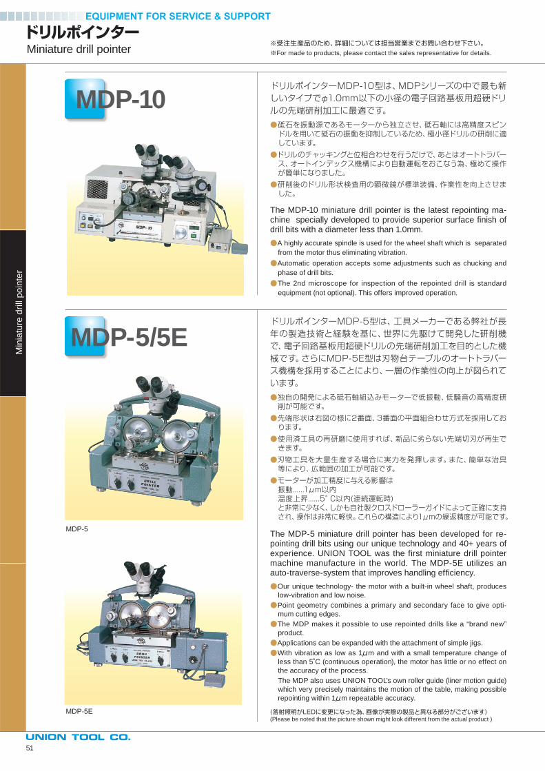
ドリルポインターMiniature drill pointer
MDP-10
MDP-5/5E
Min
iatu
re d
rill
po
inte
r
ドリルポインターMDP-10型は、MDPシリーズの中で最も新しいタイプでφ1.0mm以下の小径の電子回路基板用超硬ドリルの先端研削加工に最適です。
●砥石を振動源であるモーターから独立させ、砥石軸には高精度スピンドルを用いて砥石の振動を抑制しているため、極小径ドリルの研削に適しています。
●ドリルのチャッキングと位相合わせを行うだけで、あとはオートトラバース、オートインデックス機構により自動運転をおこなう為、極めて操作が簡単になりました。
●研削後のドリル形状検査用の顕微鏡が標準装備、作業性を向上させました。
The MDP-10 miniature drill pointer is the latest repointing ma-chine specially developed to provide superior surface fi nish of drill bits with a diameter less than 1.0mm.
●A highly accurate spindle is used for the wheel shaft which is separated
from the motor thus eliminating vibration.
●Automatic operation accepts some adjustments such as chucking and
phase of drill bits.
●The 2nd microscope for inspection of the repointed drill is standard
equipment (not optional). This offers improved operation.
ドリルポインターMDP-5型は、工具メーカーである弊社が長年の製造技術と経験を基に、世界に先駆けて開発した研削機で、電子回路基板用超硬ドリルの先端研削加工を目的とした機械です。さらにMDP-5E型は刃物台テーブルのオートトラバース機構を採用することにより、一層の作業性の向上が図られています。
●独自の開発による砥石軸組込みモーターで低振動、低騒音の高精度研削が可能です。
●先端形状は右図の様に2番面、3番面の平面組合わせ方式を採用しております。
●使用済工具の再研磨に使用すれば、新品に劣らない先端切刃が再生できます。
●刃物工具を大量生産する場合に実力を発揮します。また、簡単な治具等により、広範囲の加工が可能です。
●モーターが加工精度に与える影響は振動......1μm以内温度上昇......5°C以内(連続運転時)と非常に少なく、しかも自社製クロスドローラーガイドによって正確に支持され、操作は非常に軽快。これらの構造により1μmの繰返精度が可能です。
The MDP-5 miniature drill pointer has been developed for re-pointing drill bits using our unique technology and 40+ years of experience. UNION TOOL was the first miniature drill pointer machine manufacture in the world. The MDP-5E utilizes an auto-traverse-system that improves handling effi ciency.
●Our unique technology- the motor with a built-in wheel shaft, produces
low-vibration and low noise.
●Point geometry combines a primary and secondary face to give opti-
mum cutting edges.
●The MDP makes it possible to use repointed drills like a “brand new”
product.
●Applications can be expanded with the attachment of simple jigs.
●With vibration as low as 1μm and with a small temperature change of
less than 5˚C (continuous operation), the motor has little or no effect on
the accuracy of the process.
The MDP also uses UNION TOOL’s own roller guide (liner motion guide)
which very precisely maintains the motion of the table, making possible
repointing within 1μm repeatable accuracy.
(落射照明がLEDに変更になった為、画像が実際の製品と異なる部分がございます)(Please be noted that the picture shown might look different from the actual product )
MDP-5
MDP-5E
※受注生産品のため、詳細については担当営業までお問い合わせ下さい。※For made to products, please contact the sales representative for details.
51
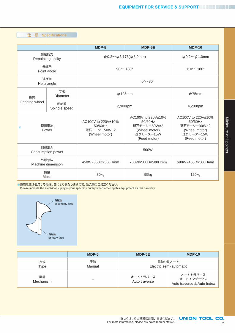
MDP-5 MDP-5E MDP-10
研削能力Repointing ability
φ0.2~φ3.175(φ5.0mm) φ0.2~φ1.0mm
先端角Point angle
90°~180° 110°~180°
逃げ角Helix angle
0°~30°
砥石Grinding wheel
寸法Diameter
φ125mm φ75mm
回転数Spindle speed
2,900rpm 4,200rpm
使用電源Power
AC100V to 220V±10%50/60Hz
砥石モーター50W×2(Wheel motor)
AC100V to 220V±10%50/60Hz
砥石モーター50W×2(Wheel motor)送りモーター15W
(Feed motor)
AC100V to 220V±10%50/60Hz
砥石モーター90W×2(Wheel motor)送りモーター15W
(Feed motor)
消費電力Consumption power
500W
外形寸法Machine dimension
450W×350D×500Hmm 700W×500D×500Hmm 690W×450D×500Hmm
質量Mass
80kg 95kg 120kg
3番面secondaly face
2番面primary face
※使用電源は使用する地域、国により異なりますので、注文時にご指定ください。 Please indicate the electrical supply in your specifi c country when ordering this equipment as this can vary.
MDP-5 MDP-5E MDP-10
方式Type
手動Manual
電動セミオートElectric semi-automatic
機構Mechanism
-オートトラバースAuto traverse
オートトラバースオートインデックス
Auto traverse & Auto Index
※
52
Min
iatu
re d
rill po
inte
r
詳しくは、担当営業にお問い合せください。For more information, please ask sales representative.
仕 様 Specifications
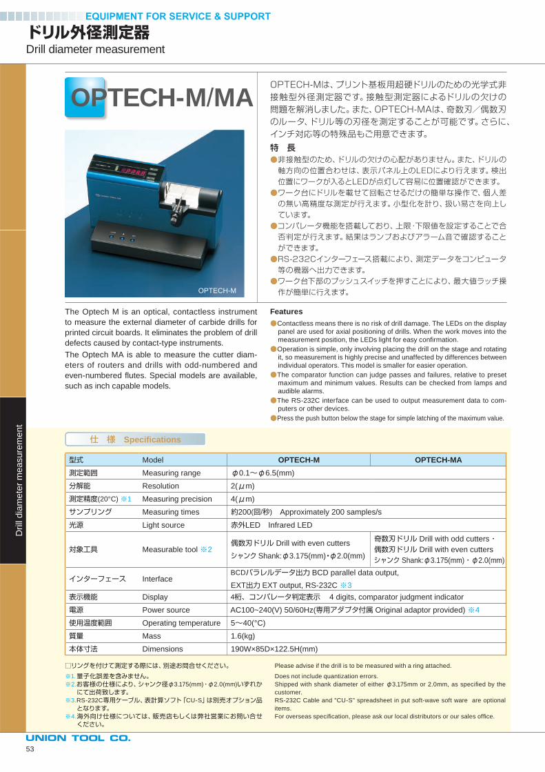
□リングを付けて測定する際には、別途お問合せください。
※1.量子化誤差を含みません。※2.お客様の仕様により、シャンク径φ3.175(mm)・φ2.0(mm)いずれかにて出荷致します。
※3.RS-232C専用ケーブル、表計算ソフト「CU-S」は別売オプション品となります。
※4.海外向け仕様については、販売店もしくは弊社営業にお問い合せください。
Please advise if the drill is to be measured with a ring attached.
Does not include quantization errors.
Shipped with shank diameter of either φ3.175mm or 2.0mm, as specifi ed by the
customer.
RS-232C Cable and "CU-S" spreadsheet in put soft-wave soft ware are optional
items.
For overseas specifi cation, please ask our local distributors or our sales offi ce.
ドリル外径測定器Drill diameter measurement
OPTECH-M/MA
Drill
dia
me
ter
me
asu
rem
en
t
仕 様 Specifications
型式 Model OPTECH-M OPTECH-MA 測定範囲 Measuring range φ0.1~φ6.5(mm)
分解能 Resolution 2(μm)
測定精度(20°C) ※1 Measuring precision 4(μm)
サンプリング Measuring times 約200(回/秒) Approximately 200 samples/s
光源 Light source 赤外LED Infrared LED
対象工具 Measurable tool ※2 偶数刃ドリル Drill with even cutters
シャンク Shank:φ3.175(mm)・φ2.0(mm)
奇数刃ドリル Drill with odd cutters・ 偶数刃ドリル Drill with even cutters
シャンク Shank:φ3.175(mm)・φ2.0(mm)
インターフェース Interface BCDパラレルデータ出力 BCD parallel data output,
EXT出力 EXT output, RS-232C ※3
表示機能 Display 4桁、コンパレータ判定表示 4 digits, comparator judgment indicator
電源 Power source AC100~240(V) 50/60Hz(専用アダプタ付属 Original adaptor provided) ※4
使用温度範囲 Operating temperature 5~40(°C)
質量 Mass 1.6(kg)
本体寸法 Dimensions 190W×85D×122.5H(mm)
OPTECH-M
OPTECH-Mは、プリント基板用超硬ドリルのための光学式非接触型外径測定器です。接触型測定器によるドリルの欠けの問題を解消しました。また、OPTECH-MAは、奇数刃/偶数刃のルータ、ドリル等の刃径を測定することが可能です。さらに、インチ対応等の特殊品もご用意できます。
特 長●非接触型のため、ドリルの欠けの心配がありません。また、ドリルの軸方向の位置合わせは、表示パネル上のLEDにより行えます。検出位置にワークが入るとLEDが点灯して容易に位置確認ができます。
●ワーク台にドリルを載せて回転させるだけの簡単な操作で、個人差の無い高精度な測定が行えます。小型化を計り、扱い易さを向上しています。
●コンパレータ機能を搭載しており、上限・下限値を設定することで合否判定が行えます。結果はランプおよびアラーム音で確認することができます。
●RS-232Cインターフェース搭載により、測定データをコンピュータ等の機器へ出力できます。
●ワーク台下部のプッシュスイッチを押すことにより、最大値ラッチ操作が簡単に行えます。
The Optech M is an optical, contactless instrument
to measure the external diameter of carbide drills for
printed circuit boards. It eliminates the problem of drill
defects caused by contact-type instruments.
The Optech MA is able to measure the cutter diam-
eters of routers and drills with odd-numbered and
even-numbered fl utes. Special models are available,
such as inch capable models.
Features●Contactless means there is no risk of drill damage. The LEDs on the display
panel are used for axial positioning of drills. When the work moves into the
measurement position, the LEDs light for easy confi rmation.
●Operation is simple, only involving placing the drill on the stage and rotating
it, so measurement is highly precise and unaffected by differences between
individual operators. This model is smaller for easier operation.
●The comparator function can judge passes and failures, relative to preset
maximum and minimum values. Results can be checked from lamps and
audible alarms.
●The RS-232C interface can be used to output measurement data to com-
puters or other devices.
●Press the push button below the stage for simple latching of the maximum value.
53
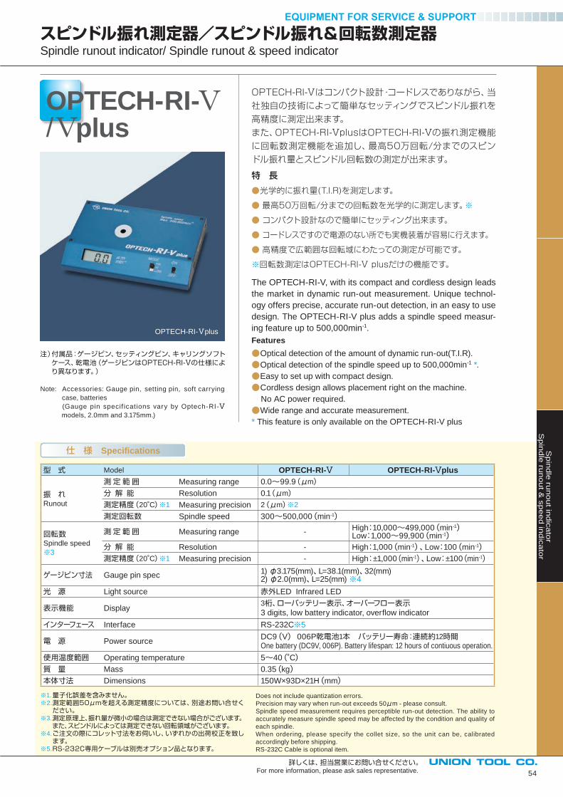
54
OPTECH-RI-/ plus
スピンドル振れ測定器/スピンドル振れ&回転数測定器Spindle runout indicator/ Spindle runout & speed indicator
Sp
ind
le ru
no
ut in
dic
ato
rS
pin
dle
run
ou
t & s
pe
ed
ind
ica
tor
詳しくは、担当営業にお問い合せください。For more information, please ask sales representative.
仕 様 Specifications
型 式 Model OPTECH-RI-Ⅴ OPTECH-RI-Ⅴplus
振 れRunout
測 定 範 囲 Measuring range 0.0~99.9(μm)
分 解 能 Resolution 0.1(μm)
測定精度(20˚C)※1 Measuring precision 2(μm)※2
測定回転数 Spindle speed 300~500,000(min-1)
回転数Spindle speed
※3
測 定 範 囲 Measuring range - High:10,000~499,000(min-1)Low:1,000~99,900(min-1)
分 解 能 Resolution - High:1,000(min-1)、Low:100(min-1)測定精度(20˚C)※1 Measuring precision - High:±1,000(min-1)、Low:±100(min-1)
ゲージピン寸法 Gauge pin spec1) φ3.175(mm)、L=38.1(mm)、32(mm) 2) φ2.0(mm)、L=25(mm) ※4
光 源 Light source 赤外LED Infrared LED
表示機能 Display 3桁、ローバッテリー表示、オーバーフロー表示3 digits, low battery indicator, overfl ow indicator
インターフェース Interface RS-232C※5
電 源 Power source DC9(V) 006P乾電池1本 バッテリー寿命:連続約12時間One battery (DC9V, 006P). Battery lifespan: 12 hours of contiuous operation.
使用温度範囲 Operating temperature 5~40(˚C)質 量 Mass 0.35(kg)本体寸法 Dimensions 150W×93D×21H(mm) ※1. 量子化誤差を含みません。※2. 測定範囲50μmを超える測定精度については、別途お問い合せください。
※3. 測定原理上、振れ量が微小の場合は測定できない場合がございます。また、スピンドルによっては測定できない回転領域がございます。
※4. ご注文の際にコレット寸法をお伺いし、いずれかの出荷校正を致します。
※5. RS-232C専用ケーブルは別売オプション品となります。
Does not include quantization errors.
Precision may vary when run-out exceeds 50μm - please consult.
Spindle speed measurement requires perceptible run-out detection. The ability to
accurately measure spindle speed may be affected by the condition and quality of
each spindle.
When ordering, please specify the collet size, so the unit can be, calibrated
accordingly before shipping.
RS-232C Cable is optional item.
OPTECH-RI-Ⅴplus
OPTECH-RI-Ⅴはコンパクト設計・コードレスでありながら、当
社独自の技術によって簡単なセッティングでスピンドル振れを
高精度に測定出来ます。
また、OPTECH-RI-ⅤplusはOPTECH-RI-Ⅴの振れ測定機能
に回転数測定機能を追加し、最高50万回転/分までのスピン
ドル振れ量とスピンドル回転数の測定が出来ます。
特 長
●光学的に振れ量(T.I.R)を測定します。
● 最高50万回転/分までの回転数を光学的に測定します。※
● コンパクト設計なので簡単にセッティング出来ます。
● コードレスですので電源のない所でも実機装着が容易に行えます。
● 高精度で広範囲な回転域にわたっての測定が可能です。
※回転数測定はOPTECH-RI-Ⅴ plusだけの機能です。
The OPTECH-RI-V, with its compact and cordless design leads
the market in dynamic run-out measurement. Unique technol-
ogy offers precise, accurate run-out detection, in an easy to use
design. The OPTECH-RI-V plus adds a spindle speed measur-
ing feature up to 500,000min-1.
Features●Optical detection of the amount of dynamic run-out(T.I.R).
●Optical detection of the spindle speed up to 500,000min-1 *.
●Easy to set up with compact design.
●Cordless design allows placement right on the machine.
No AC power required.
●Wide range and accurate measurement.
* This feature is only available on the OPTECH-RI-V plus
注)付属品:ゲージピン、セッティングピン、キャリングソフト ケース、乾電池(ゲージピンはOPTECH-RI-Ⅴの仕様によ り異なります。)
Note: Accessories: Gauge pin, setting pin, soft carrying
case, batteries
(Gauge pin specif ications vary by Optech-RI-Ⅴmodels, 2.0mm and 3.175mm.)
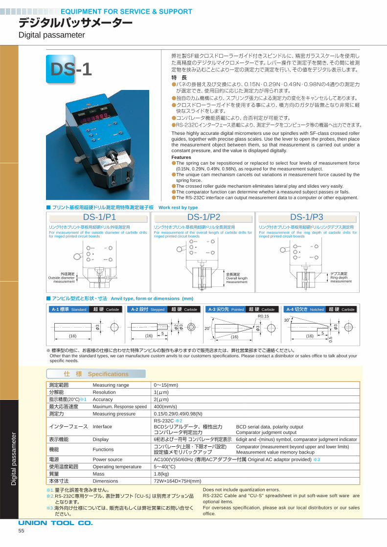
リング付きプリント基板用超硬ドリル外径測定用For measurement of the outside diameter of carbide drills for ringed printed circuit boards
リング付きプリント基板用超硬ドリル全長測定用For measurement of the overall length of carbide drills for ringed printed circuit boards
リング付きプリント基板用超硬ドリルリングデプス測定用For measurement of the ring depth of carbide drills for ringed printed circuit boards
DS-1/P1 DS-1/P2 DS-1/P3
外径測定Outside diameter
measurement
全長測定Overall length measurement
デプス測定Ring-depth measurement
A-1 標準 Standard 超 硬 Carbide A-2 段付 Stepped 超 硬 Carbide A-3 尖り先 Pointed 超 硬 Carbide
φ3
φ3
φ3 φ3
20˚
30˚
φ2
(16) (16)5
(16) (16)
R0.15
0.5
5
A-4 切欠き Notched 超 硬 Carbide
測定範囲 Measuring range 0~15(mm)
分解能 Resolution 1(μm)
指示精度(20°C)※1 Accuracy 2(μm)
最大応答速度 Maximum. Response speed 400(mm/s)
測定力 Measuring pressure 0.15/0.29/0.49/0.98(N)
インターフェース Interface
RS-232C ※2
BCDシリアルデータ、極性出力 BCD serial data, polarity outputコンパレータ判定出力 Comparator judgment output
表示機能 Display 6桁および-符号 コンパレータ判定表示 6digit and -(minus) symbol, comparator judgment indicator
機能 Functionsコンパレータ(上限・下限オーバ設定) Comparator (measurement beyond upper and lower limits)設定値メモリバックアップ Measurement value memory backup
電源 Power source AC100(V)50/60Hz (専用ACアダプター付属 Original AC adaptor provided) ※3
使用温度範囲 Operating temperature 5~40(°C)
質量 Mass 1.8(kg)
本体寸法 Dimensions 72W×164D×75H(mm)
デジタルパッサメーターDigital passameter
DS-1
Dig
ita
l p
assa
me
ter
■ プリント基板用超硬ドリル測定用特殊測定端子板 Work rest by type
■ アンビル型式と形状・寸法 Anvil type, form or dimensions (mm)
※標準型の他に、お客様の仕様に合わせた特殊アンビルの製作も承りますので販売店または、弊社営業部までご連絡ください。 Other than the standard types, we can manufacture custom anvils to our customers specifi cations. Please contact a distributor or sales offi ce to talk about your specifi c needs.
仕 様 Specifications
※1.量子化誤差を含みません。※2.RS-232C専用ケーブル、表計算ソフト「CU-S」は別売オプション品となります。
※3.海外向け仕様については、販売店もしくは弊社営業にお問い合せください。
Does not include quantization errors.
RS-232C Cable and "CU-S" spreadsheet in put soft-wave soft ware are
optional items.
For overseas specifi cation, please ask our local distributors or our sales
offi ce.
弊社製SF級クロスドローラーガイド付きスピンドルに、精密ガラススケールを使用した高精度のデジタルマイクロメーターです。レバー操作で測定子を開き、その間に被測定物を挟み込むことにより一定の測定力で測定を行い、その値をデジタル表示します。
特 長●バネの掛替え及び交換により、0.15N・0.29N・0.49N・0.98Nの4通りの測定力が選定でき、使用目的に応じた測定力が得られます。
●独自のカム機構により、スプリング張力による測定力の変化をキャンセルしてあります。●クロスドローラーガイドを使用する事により、横方向のガタが皆無となり非常に軽快なスライドをします。●コンパレータ機能搭載により、合否判定が可能です。●RS-232Cインターフェース搭載により、測定データをコンピュータ等の機器へ出力できます。
These highly accurate digital micrometers use our spindles with SF-class crossed roller
guides, together with precise glass scales. Use the lever to open the probes, then place
the measurement object between them, so that measurement is carried out under a
constant pressure, and the value is displayed digitally.
Features●The spring can be repositioned or replaced to select four levels of measurement force
(0.15N, 0.29N, 0.49N, 0.98N), as required for the measurement subject.
●The unique cam mechanism cancels out variations in measurement force caused by the
spring force.
●The crossed roller guide mechanism eliminates lateral play and slides very easily.
●The comparator function can determine whether a measured subject passes or fails.
●The RS-232C interface can output measurement data to a computer or other equipment.
55
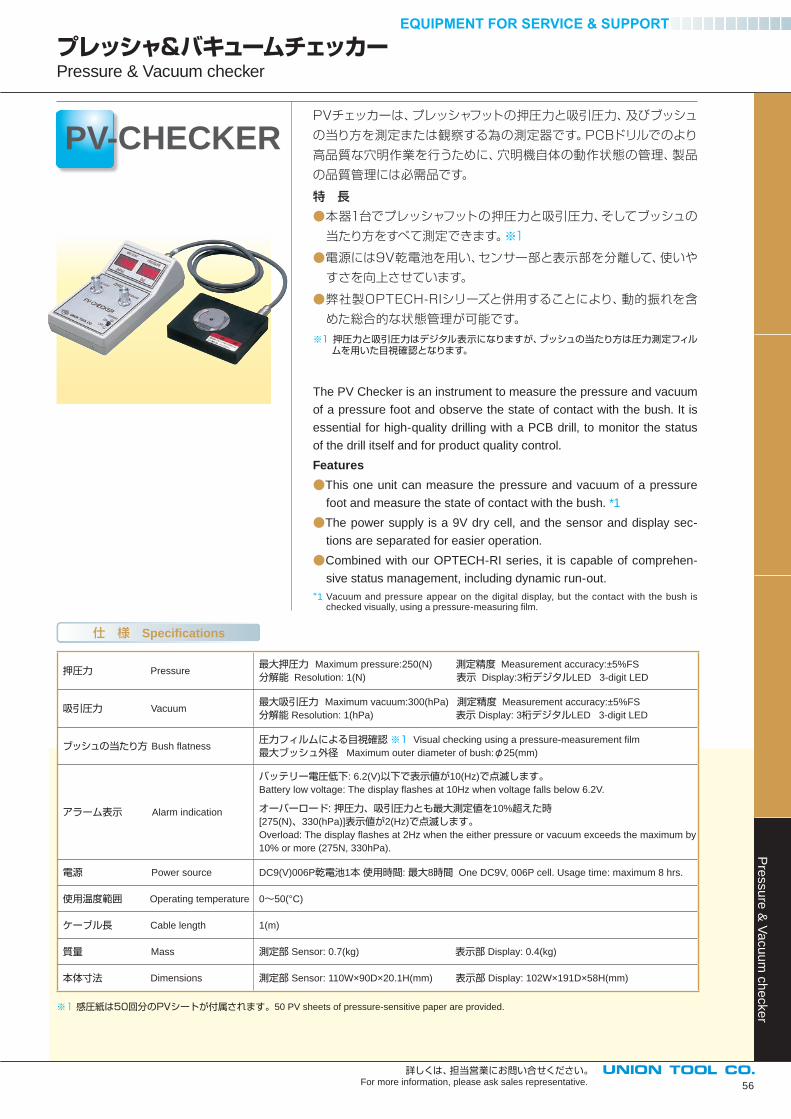
56
PV-CHECKER
プレッシャ&バキュームチェッカーPressure & Vacuum checker
Pre
ssu
re &
Va
cu
um
ch
ecke
r
詳しくは、担当営業にお問い合せください。For more information, please ask sales representative.
※1 感圧紙は50回分のPVシートが付属されます。50 PV sheets of pressure-sensitive paper are provided.
仕 様 Specifications
押圧力 Pressure最大押圧力 Maximum pressure:250(N) 測定精度 Measurement accuracy:±5%FS
分解能 Resolution: 1(N) 表示 Display:3桁デジタルLED 3-digit LED
吸引圧力 Vacuum最大吸引圧力 Maximum vacuum:300(hPa) 測定精度 Measurement accuracy:±5%FS
分解能 Resolution: 1(hPa) 表示 Display: 3桁デジタルLED 3-digit LED
ブッシュの当たり方 Bush fl atness圧力フィルムによる目視確認 ※1 Visual checking using a pressure-measurement fi lm
最大ブッシュ外径 Maximum outer diameter of bush:φ25(mm)
アラーム表示 Alarm indication
バッテリー電圧低下: 6.2(V)以下で表示値が10(Hz)で点滅します。Battery low voltage: The display fl ashes at 10Hz when voltage falls below 6.2V.
オーバーロード: 押圧力、吸引圧力とも最大測定値を10%超えた時[275(N)、330(hPa)]表示値が2(Hz)で点滅します。Overload: The display fl ashes at 2Hz when the either pressure or vacuum exceeds the maximum by
10% or more (275N, 330hPa).
電源 Power source DC9(V)006P乾電池1本 使用時間: 最大8時間 One DC9V, 006P cell. Usage time: maximum 8 hrs.
使用温度範囲 Operating temperature 0~50(°C)
ケーブル長 Cable length 1(m)
質量 Mass 測定部 Sensor: 0.7(kg) 表示部 Display: 0.4(kg)
本体寸法 Dimensions 測定部 Sensor: 110W×90D×20.1H(mm) 表示部 Display: 102W×191D×58H(mm)
PVチェッカーは、プレッシャフットの押圧力と吸引圧力、及びブッシュ
の当り方を測定または観察する為の測定器です。PCBドリルでのより
高品質な穴明作業を行うために、穴明機自体の動作状態の管理、製品
の品質管理には必需品です。
特 長
●本器1台でプレッシャフットの押圧力と吸引圧力、そしてブッシュの
当たり方をすべて測定できます。※1
●電源には9V乾電池を用い、センサー部と表示部を分離して、使いや
すさを向上させています。
●弊社製OPTECH-RIシリーズと併用することにより、動的振れを含
めた総合的な状態管理が可能です。
※1 押圧力と吸引圧力はデジタル表示になりますが、ブッシュの当たり方は圧力測定フィル ムを用いた目視確認となります。
The PV Checker is an instrument to measure the pressure and vacuum
of a pressure foot and observe the state of contact with the bush. It is
essential for high-quality drilling with a PCB drill, to monitor the status
of the drill itself and for product quality control.
Features●This one unit can measure the pressure and vacuum of a pressure
foot and measure the state of contact with the bush. *1
●The power supply is a 9V dry cell, and the sensor and display sec-
tions are separated for easier operation.
●Combined with our OPTECH-RI series, it is capable of comprehen-
sive status management, including dynamic run-out.
*1 Vacuum and pressure appear on the digital display, but the contact with the bush is checked visually, using a pressure-measuring fi lm.
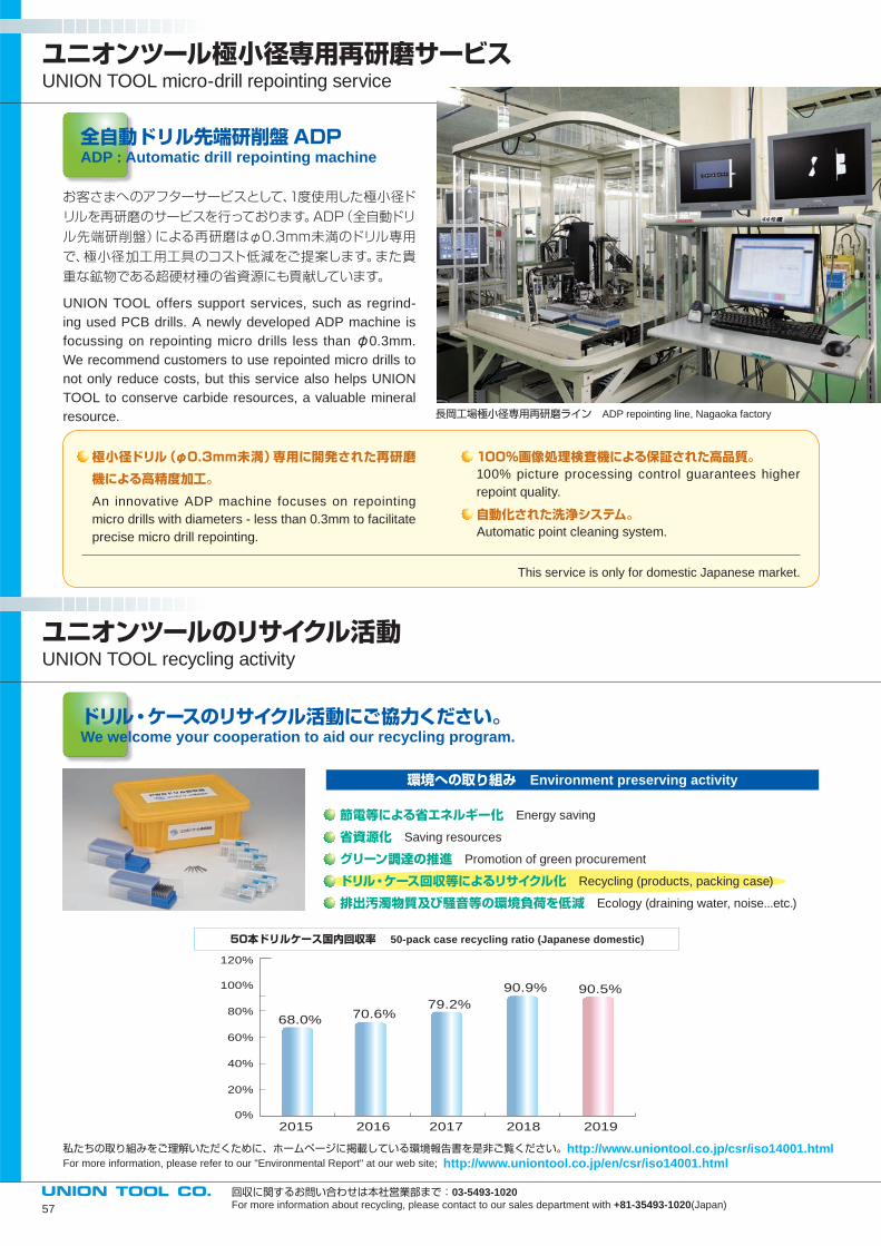
ユニオンツール極小径専用再研磨サービスUNION TOOL micro-drill repointing service
ユニオンツールのリサイクル活動UNION TOOL recycling activity
全自動ドリル先端研削盤ADPADP : Automatic drill repointing machine
お客さまへのアフターサービスとして、1度使用した極小径ド
リルを再研磨のサービスを行っております。ADP(全自動ドリ
ル先端研削盤)による再研磨はφ0.3mm未満のドリル専用
で、極小径加工用工具のコスト低減をご提案します。また貴
重な鉱物である超硬材種の省資源にも貢献しています。
UNION TOOL offers support services, such as regrind-
ing used PCB drills. A newly developed ADP machine is
focussing on repointing micro drills less than φ0.3mm.
We recommend customers to use repointed micro drills to
not only reduce costs, but this service also helps UNION
TOOL to conserve carbide resources, a valuable mineral
resource.
極小径ドリル(φ0.3mm未満)専用に開発された再研磨
機による高精度加工。
An innovative ADP machine focuses on repointing
micro drills with diameters - less than 0.3mm to facilitate
precise micro drill repointing.
100%画像処理検査機による保証された高品質。100% picture processing control guarantees higher
repoint quality.
自動化された洗浄システム。Automatic point cleaning system.
This service is only for domestic Japanese market.
ドリル・ケースのリサイクル活動にご協力ください。We welcome your cooperation to aid our recycling program.
環境への取り組み Environment preserving activity
節電等による省エネルギー化 Energy saving
省資源化 Saving resources
グリーン調達の推進 Promotion of green procurement
ドリル・ケース回収等によるリサイクル化 Recycling (products, packing case)
排出汚濁物質及び騒音等の環境負荷を低減 Ecology (draining water, noise...etc.)
回収に関するお問い合わせは本社営業部まで:03-5493-1020For more information about recycling, please contact to our sales department with +81-35493-1020(Japan)
私たちの取り組みをご理解いただくために、ホームページに掲載している環境報告書を是非ご覧ください。http://www.uniontool.co.jp/csr/iso14001.htmlFor more information, please refer to our "Environmental Report" at our web site; http://www.uniontool.co.jp/en/csr/iso14001.html
2015 2016 2017 2018 2019
100%
120%
80%
60%
40%
20%
0%
68.0%70.6%
79.2%
90.9% 90.5%
50本ドリルケース国内回収率 50-pack case recycling ratio (Japanese domestic)
長岡工場極小径専用再研磨ライン ADP repointing line, Nagaoka factory
57
58
●切刃に直接触れると怪我をすることがありますので、ケースから抜き取る際には充分注意して下さい。
●ケースを落とした場合、飛散した刃先で怪我をすることがありますので、取り扱いに注意して下さい。
●高速回転で使用する為、折損して飛散することがありますので、止む得ず覗き込むときは必ず保護眼鏡、マスクを着用してください。
●再研磨時は、超硬合金を使用しておりますので研磨塵が目に入らないよう必ず保護眼鏡を着用してください。
●再研磨時は、研磨塵をすいこまないよう必ずマスクをかけてください。
When opening a case to remove drill bits, do not touch
the cutting edge.
PCB cutting tools operate at high R.P.M levels that are
inherently dangerous, eye protection is required.
All PCB cutting Tools are manufactured from tungsten
carbide materials that can produce potentially harmful
particles of dust during repointing. Do not inhale this
articulate dust matter.
UNION TOOL PCB cutting tools are sold under the
terms of the following limited warranty only : Liability is
limited to replacement of defective cutting tool(s). No
warranty of merchantability or liability for consequential
of secondary damages is expressed or implied.
安全上の指示事項 SAFETY WARNING
専用オープナーの使い方How to use "drill case opener"
ドリル・ルーターケースを開ける場合は、必ず専用オープ
ナーをご使用ください。
(詳しくは、担当営業にお問い合わせください。)
When opening 10pcs pack case for drills & router bits,
please use " drill case opener".
オープナーの先端の突起をケース
上部に引っ掛け、オープナーを時
計回り(矢印方向)に回すと簡単に
開けることが出来ます。
If you hook the two points to the
sides of the upper part of the
case and twist it clockwise (to
the direction of the arrow) you
can open the case easily.
https://www.uniontool.co.jp
〒140-0013 東京都品川区南大井6-17-1
TEL.03-5493-1021(ダイヤルイン) FAX.03-5493-1019
6-17-1 Minami-Ohi, Shinagawa-Ku, Tokyo, 140-0013, JAPAN
TEL:+81-35493-1008 FAX:+81-35493-1019
長岡工場・テクニカルセンター・営業所〒940-1104 新潟県長岡市摂田屋町字外川 2706-6
長岡工場・営業所TEL.0258-22-2620(代) FAX.0258-22-0045
テクニカルセンターTEL.0258-22-0151(代) FAX.0258-22-0246
NAGAOKA FACTORY & TECHNICAL CENTER & SALES OFFICE 2706-6 Togawa, Settaya-machi, Nagaoka-shi, Niigata pref, 940-1104, JAPANFACTORY & SALES OFFICETEL.+81-258-22-2620 FAX.+81-258-22-0045TECHNICAL CENTERTEL.+81-258-22-0151 FAX.+81-258-22-0246
安城営業所〒446-0056 愛知県安城市三河安城町2-1-1
ミカワ安城ヒルズ2F-A
TEL.0566-79-0147(代) FAX.0566-74-9990
ANJO SALES OFFICEMikawa Anjo Hills 2F-A, 2-1-1 Mikawa Anjo-cho,Anjo-shi, Aichi pref, 446-0056, JAPANTEL.+81-566-79-0147 FAX.+81-566-74-9990
名古屋営業所 〒491-0912 愛知県一宮市新生1-2-8ニッセイ一宮ビル8F
TEL.0586-43-2900(代) FAX.0586-43-2899
NAGOYA SALES OFFICENISSAY Ichinomiya BLDG 8F, 1-2-8 Shinsei, Ichinomiya-shi, Aichi pref, 491-0912, JAPANTEL.+81-586-43-2900 FAX.+81-586-43-2899
大阪営業所〒532-0033 大阪府大阪市淀川区新高3-9-14
ピカソ三国ビル3F
TEL.06-6392-3159(代) FAX.06-6392-3169
OSAKA SALES OFFICEpicAsso Mikuni Building 3F, 3-9-14 Niitaka, Yodogawa-ku, Osaka-shi, Osaka 532-0033, JAPANTEL.+81-6-6392-3159 FAX.+81-6-6392-3169
見附工場〒954-0076 新潟県見附市新幸町3-1
TEL.0258-66-0800(代) FAX.0258-66-0801
MITSUKE FACTORY3-1 Shinko-cho, Mitsuke-shi,Niigata pref, 954-0076, JAPANTEL.+81-258-66-0800 FAX.+81-258-66-0801
北関東営業所〒370-0046 群馬県高崎市江木町1425番地セシオン101号室TEL.027-310-1195(代) FAX.027-310-1196
KITAKANTO SALES OFFICESesion 101, 1425 Egi-machi, Takasaki-shi,Gunma pref, 370-0046, JAPANTEL.+81-27-310-1195 FAX.+81-27-310-1196
UNION TOOL EUROPE S.A.Avenue des Champs-Montants, 14aCH-2074 MARIN / NE SWITZERLANDTEL.+41-32-756-6633 FAX.+41-32-756-6634
TAIWAN UNION TOOL CORP.No.180, Zhong-Zun Street, 14 Neighborhood, Bin-Hai Vil., Lu-Zhu Dist., Taoyuan City, 338 TAIWANTEL.+886-3-354-3111 FAX.+886-3-354-3110
UNION TOOL (SHANGHAI) CO., LTD.No.9-10 Lane 385, Gaoji Road, Sijing High New Technology Development Zone, Songjiang District, Shanghai 201601, CHINATEL.+86-21-5762-8577 FAX.+86-21-5762-8436
DONGGUAN UNION TOOL LTD.YingHua TaiYing Industry Park, Hongmei Town, Dongguan City, Guangdong 523160 CHINATEL.+86-769-88848901 FAX.+86-769-88848296
UNION TOOL HONG KONG LTD.Rm 503, 5/F, Win Century Centre, 2A Mong Kok Rd, Mong Kok, Kowloon, HONG KONGTEL.+852-2370-3012 FAX.+852-2370-2111
U.S. UNION TOOL, INC. (U. S. HEADQUARTERS)1260 North Fee Ana Street, Anaheim, CA 92807-1817 U.S.A. TEL.+1-714-521-6242 FAX.+1-714-521-8642
UNION TOOL SINGAPORE PTE LTD.No.31 Harrison Road, #05-01, SINGAPORE 369649TEL.+65-6846-9309 FAX.+65-6846-0197
UNION TOOL (THAILAND) CO., LTD. No.55/73 Moo 15 Bangsaotong Sub-District, Bangsaotong District, Samutprakarn 10570 THAILANDTEL.+66-2-130-0908 FAX.+66-2-130-0909
NORTHERN CALIFORNIA REGIONAL SERVICE CENTER(Customer Service, San Jose, California) 1805 Little Orchard Street, Suite 120, San Jose, CA 95125, U.S.A.TEL.+1-408-982-0205 FAX.+1-408-982-0320
UPPER MIDWEST REGIONAL SERVICE CENTER(Customer Service, Minneapolis, Minnesota)155 Bridgepoint Drive, Unit 3 South St.Paul, MN 55075 U.S.A. TEL.+1-651-552-0440 FAX. +1-651-552-0435
三島研究所〒411-0951 静岡県駿東郡長泉町桜堤3-4-5
TEL.055-989-3401(代) FAX.055-989-3410
MISHIMA LABORATORY3-4-5 Sakurazutsumi, Nagaizumi-cho,Sunto-gun, Shizuoka pref, 411-0951, JAPANTEL.+81-55-989-3401 FAX.+81-55-989-3410
製品についてのお問い合わせは下記まで
0120-60-2620受付時間: 9:30~12:00、13:00~16:30(土曜、日曜、祝日、弊社休日を除く)