Embed Size (px)
Citation preview
General rights Copyright and moral rights for the publications made accessible in the public portal are retained by the authors and/or other copyright owners and it is a condition of accessing publications that users recognise and abide by the legal requirements associated with these rights.
Users may download and print one copy of any publication from the public portal for the purpose of private study or research.
You may not further distribute the material or use it for any profit-making activity or commercial gain
You may freely distribute the URL identifying the publication in the public portal If you believe that this document breaches copyright please contact us providing details, and we will remove access to the work immediately and investigate your claim.
Downloaded from orbit.dtu.dk on: Feb 04, 2019
Tuned mass dampers on damped structures
Krenk, Steen; Høgsberg, Jan Becker
Published in:7th European Conference on Structural Dynamics
Publication date:2008
Document VersionPublisher's PDF, also known as Version of record
Link back to DTU Orbit
Citation (APA):Krenk, S., & Høgsberg, J. B. (2008). Tuned mass dampers on damped structures. In M. J. Brennan (Ed.), 7thEuropean Conference on Structural Dynamics Southampton, United Kingdom: University of Southampton.
TUNED MASS ABSORBERS ON DAMPED STRUCTURES
Steen Krenk and Jan Høgsberg
Department of Mechanical EngineeringTechnical University of Denmark
Nils Koppels Alle, DK-2800 Lyngby, Denmarke-mail: [email protected]; [email protected]
Keywords: Tuned mass absorber, TMD, random vibration, structural dynamics
ABSTRACT
A design procedure is presented for tuned mass absorbers mounted on structures with structuraldamping. It is demonstrated that by minor modifications of the spectral density integrals veryaccurate explicit results can be obtained for the variance of the response to wide band randomexcitation. It is found that the design can be based on the classic frequency tuning, leading toequal damping ratio for the two modes, and an accurate explicit approximation is found for theoptimal damping parameter of the absorber and the resultingdamping ratio for the response.
1. INTRODUCTION
Tuned mass absorbers constitute an efficient means of introducing damping into structures proneto vibrations, e.g. bridges and high-rise buildings. The original idea is due to Frahm in 1909,who introduced a spring supported mass, tuned to the naturalfrequency of the oscillation tobe reduced. It was demonstrated by Ormondroyd & Den Hartog [1] that the introduction of adamper in parallel with the spring support of the tuned mass leads to improved behavior, e.g. inthe form of amplitude reduction over a wider range of frequencies. The standard reference tothe classic tuned mass absorber is the textbook of Den Hartog[2] describing optimal frequencytuning for harmonic load, and the procedure of Brock [3] for the optimal damping. A detailedanalysis of the frequency response properties of the tuned mass absorber has recently been pre-sented by Krenk [4] who demonstrated that the classic frequency tuning leads to equal dampingratio of the two complex modes resulting from the coupled motion of the structural mass andthe damper mass. An optimal damping ratio of the absorber wasdetermined that improves onthe classic result of Brock. These results are all based on a frequency response analysis, wherea root locus analysis can be used to determine the complex natural frequencies of the modes andthereby the damping ratio, while optimal response characteristics are obtained by considerationof the frequency response diagrams for the response amplitude. The results can be obtained inexplicit form only when the original structure is undamped.Results including structural damp-ing have been obtained by Fujino & Abe [5] via a perturbation analysis based on the undampedcase.
E61
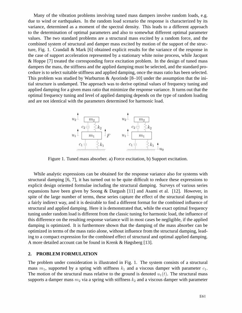
Many of the vibration problems involving tuned mass dampersinvolve random loads, e.g.due to wind or earthquakes. In the random load scenario the response is characterized by itsvariance, determined as a moment of the spectral density. This leads to a different approachto the determination of optimal parameters and also to somewhat different optimal parametervalues. The two standard problems are a structural mass excited by a random force, and thecombined system of structural and damper mass excited by motion of the support of the struc-ture, Fig. 1. Crandall & Mark [6] obtained explicit results for the variance of the response inthe case of support acceleration represented by a stationary white noise process, while Jacquot& Hoppe [7] treated the corresponding force excitation problem. In the design of tuned massdampers the mass, the stiffness and the applied damping mustbe selected, and the standard pro-cedure is to select suitable stiffness and applied damping,once the mass ratio has been selected.This problem was studied by Warburton & Ayorinde [8–10] under the assumption that the ini-tial structure is undamped. The approach was to derive optimal values of frequency tuning andapplied damping for a given mass ratio that minimize the response variance. It turns out that theoptimal frequency tuning and level of applied damping depends on the type of random loadingand are not identical with the parameters determined for harmonic load.
m2
c2 k2
m1
c1 k1
u1
u2
F
m2
c2 k2
m1
c1 k1
u1
u2
u0
Figure 1. Tuned mass absorber. a) Force excitation, b) Support excitation.
While analytic expressions can be obtained for the response variance also for systems withstructural damping [6, 7], it has turned out to be quite difficult to reduce these expressions toexplicit design oriented formulae including the structural damping. Surveys of various seriesexpansions have been given by Soong & Dargush [11] and Asami et al. [12]. However, inspite of the large number of terms, these series capture the effect of the structural damping ina fairly indirect way, and it is desirable to find a different format for the combined influence ofstructural and applied damping. Here it is demonstrated that, while the exact optimal frequencytuning under random load is different from the classic tuning for harmonic load, the influence ofthis difference on the resulting response variance will in most cases be negligible, if the applieddamping is optimized. It is furthermore shown that the damping of the mass absorber can beoptimized in terms of the mass ratio alone, without influencefrom the structural damping, lead-ing to a compact expression for the combined effect of structural and optimal applied damping.A more detailed account can be found in Krenk & Høgsberg [13].
2. PROBLEM FORMULATION
The problem under consideration is illustrated in Fig. 1. The system consists of a structuralmassm1, supported by a spring with stiffnessk1 and a viscous damper with parameterc1.The motion of the structural mass relative to the ground is denotedu1(t). The structural masssupports a damper massm2 via a spring with stiffnessk2 and a viscous damper with parameter
E61
c2. The motion of the damper relative to the ground is denotedu2(t). Two situations will beinvestigated: a) motion due to a forceF (t) acting on the structural mass, and b) motion due toaccelerationu0(t) of the supporting ground.
The motion of the two-degree-of-freedom system is described by a frequency analysis withangular frequencyω and displacement amplitude vectoru = [u1, u2]
T ,
(
K + iωC − ω2M
)
u = F (1)
whereF = [F1, F2]T is the force amplitude vector, and the mass, damping and stiffness matrices
are given by
M =
[
m1 00 m2
]
, C =
[
c1+c2 −c2
−c2 c2
]
, K =
[
k1+k2 −k2
−k2 k2
]
(2)
The stiffness parameters are expressed in terms of representative frequencies,
ω1 =√
k1/m1 , ω2 =√
k2/m2 (3)
and the damping parameters are expressed in terms of the damping ratios,
2ζ1 =c1√
k1 m1
, 2ζ2 =c2√
k2 m2
(4)
The relative mass and time scale of the secondary mass are described by the mass ratioµ andthe frequency tuning parameterα,
µ =m2
m1
, α =ω2
ω1
(5)
In the typical tuned mass design problem the final damping is controlled byµ, and optimalproperties are obtained by proper selection of the frequency tuning parameterα and the dampingratio ζ2.
Analytic results are obtained for the idealized case of white noise, representing wide-bandexcitation. The quality of the damper system is defined via its ability to limit the variance of theresponse of the primary mass,σ2
1= Var[u1]. The analysis is therefore based on the frequency
transfer function for the componentu1 alone. It is convenient to introduce the frequency ratior = ω/ω1 and to introduce the normalized forcef = F/k1, whereby (1) takes the form
[
1+µα2−r2+ 2i(ζ1+µαζ2)r −µα2−2iµαζ2r−µα2−2iµαζ2r µα2−µr2+2iµαζ2r
] [
u1
u2
]
=
[
f1
f2
]
(6)
Only special load processes will be treated here, and it is therefore convenient to discuss thetwo cases separately.
3. FORCED MOTION
In the case of forced motion there is only one load vector componentF (t), acting on the struc-tural mass. The corresponding normalized load vector is,
f =
[
f0
]
=
[
F/k1
0
]
(7)
E61
where the componentf = F/k1 corresponds to the quasi-static displacement of the structuralmass. The responseu1 of the structural mass follows from (6) as
u1 = Hf (ω) f (8)
The frequency response functionHf (ω) of the forced motion is a rational function of the form
Hf (ω) =pf (ω)
q(ω)(9)
with numeratorpf (ω) = α2−r2+2iαζ2r (10)
and denominator
q(ω) = [ 1+µα2−r2 + 2i(ζ1+µαζ2)r ][ α2−r2+2iαζ2r ] − µ[ α2+2iαζ2r ]2 (11)
Let the force be represented by a white noise process, and letthe normalized force processf(t) = F (t)/k1 have the spectral densitySf . The variance of the responseσ2
1can then be
evaluated from the integral,
σ2
1= Sf
∫
∞
−∞
|Hf (ω)|2 dω = Sf
∫
∞
−∞
Hf (ω) Hf (−ω) dω (12)
The poles of the rational frequency transfer functionHf (ω) all lie in the upper complex half-plane. This type of integral can be evaluated directly from the coefficients of the polynomialsin the numerator and denominator [14],
σ2
1=
π
2Sf ω1
Pf (µ, α, ζ1, ζ2)
Q(µ, α, ζ1, ζ2)(13)
wherePf andQ are polynomials in the coefficients ofpf (r) andq(r), respectively, and therebyin the indicated arguments. After some algebra the result can be written as
Pf = µα2(αζ1 + ζ2) + [ 1 − (1 + µ)α2]2ζ2 + 4αζ2[ζ1 + (1 + µ)αζ2](αζ1 + ζ2) (14)
and
Q = µα(αζ1 + ζ2)2 + [ 1 − (1 + µ)α2]2ζ1ζ2 + 4αζ1ζ2 [ ζ1 + (1 + µ)αζ2](αζ1 + ζ2) (15)
It is seen that all terms inPf are linear or cubic in the damping ratiosζ1 andζ2, while all termsin Q are quadratic or quartic. In spite of this property, and the fact that several of the factorsoccur repeatedly, the general form of the exact result seemsto be intractable analytically. In thefollowing the result will be analyzed in two steps. First an analysis of the system without struc-tural damping is used to demonstrate that the frequency tuning corresponding to a bifurcationpoint in the root locus diagram can be used as a fairly good representative for optimal frequencytuning in the case of random load, and subsequently simple and quite accurate approximationsfor the damping parameters and properties.
E61

3.1 Undamped primary structure
In the absence of structural damping,ζ1 = 0, the expression (13) for the response variancesimplifies considerably,
σ2
1=
π
2
Sfω1
αζ2
[
α2 +1
µ
(
1 − (1 + µ)α2)2
+4
µ(1 + µ)(αζ2)
2
]
(16)
The minimum value of the variance is conveniently found by considering minimizing this ex-pression with the parameter combinationsαζ2 andα2 as independent variables. This leads tothe optimal frequency tuning ratioα and optimal damping ratioζ2 determined by
α2 =1 + 1
2µ
(1 + µ)2, ζ2
2=
µ
4(1 + µ)
1 + 3
4µ
1 + 1
2µ
(17)
The minimum response variance is found by substituting these optimum values into the responsevariance expression (16),
σ2
1,min = 2πSfω1
√
1 + 3
4µ
µ(1 + µ)(18)
These are the classic expressions for optimal frequency anddamping, and resulting responsevariance [6, 8, 10].
Alternatively the frequency tuning can be selected as
α =1
1 + µ(19)
corresponding to a bifurcation point in the root locus diagram and equal damping of the twomodes of the system, [4]. When using this frequency tuning, the optimal damping ratio followsfrom minimizing (16) as
ζ2 =
õ
2(20)
The corresponding value of the response variance is
σ2
1=
2π√µ
Sfω1 =π
ζ2
Sfω1 (21)
These expressions are remarkably simple. Furthermore the ratio of the minimum standard de-viationσ1,min to this value is
σ1,min
σ1
=4
√
1 + 3
4µ
1 + µ≃ 1 − 1
16µ + · · · (22)
In most practical cases the mass ratio is of the order of a few percent, leading to a relativedifference in the standard deviation of the response of the order 0.001. In view of this thesimple frequency tuningα = (1 + µ)−1 is used as basis for the development of an approximatebut accurate set of formulae for the general case of random load.
E61
3.2 Damped primary structure
In the case of the classic frequency tuning for harmonic load(19) the rational expression (13)for the response variance simplifies. The polynomial in the numerator now takes the form
Pf = µα(α2ζ1 + ζ2) + 4αζ2(ζ1 + ζ2)(αζ1 + ζ2) (23)
When the mass ratio is small, the frequency tuning parameter is close to 1, and for optimaldamping the total damping will be in the order of
õ. In typical applications the structural
dampingζ1 will furthermore be small relative to the applied dampingζ2. Under these conditionsexchange of the factorα2 in the first parenthesis withα will have only modest effect on thenumerical value, while leading to a factored form. The polynomial in the denominator of (13)can be factored by a similar approximation. The classic harmonic frequency tuning (13) gives
Q = µα[
α2ζ2
1+ ζ2
2+ (1 + α)ζ1ζ2
]
+ 4αζ1ζ2 (ζ1 + ζ2)(αζ1 + ζ2) (24)
Again, replacement of the factorα2 with α in the first term leads to a factored form. Whenthe approximate factored forms are used in the expression (13) for the response variance, thefollowing simple expression is obtained
σ2
1≃ π
2
Sfω1
ζ1 + ζ2
µ + 4ζ2(ζ1 + ζ2)
µ + 4ζ1ζ2
(25)
This approximation contains the exact result in both the limit of vanishing structural damping,ζ1 = 0, and in the absence of imposed damping,ζ2 = 0.
For a general combination of damping its effect can be expressed in terms of an effectivedamping ratioζeff, defined by analogy with the formula for structural damping alone, as
σ2
1=
π
2
Sfω1
ζeff(26)
It follows from (25) that the effective damping is given by
ζeff = ζ1 +µ ζ2
µ + 4ζ2(ζ1 + ζ2)(27)
Minimum response variance is obtained for maximum effective damping, and thus the last termin (27) should be maximized. When minimizing its reciprocal,the result can be read off directlyas
ζ2,opt =
õ
2, ζ1 ≥ 0 (28)
This leads to the interesting conclusion that the magnitudeof the optimal applied dampingdepends only on the mass ratio, but is independent of the structural damping. The correspondingeffective damping ratio is
ζeff,opt = ζ1 +ζ2
2
ζ1 + 2ζ2
=(ζ1 + ζ2)
2
ζ1 + 2ζ2
(29)
with the optimized response variance
σ2
1,opt =π
2
ζ1 + 2ζ2
(ζ1 + ζ2)2Sfω1 (30)
E61

0 5 100
5
10
15
ζ2 = 1
2
õ
ζ eff
Figure 2: Effective damping ratioζeff in % for force excitation. Full lines for explicit approxi-mation and dots for optimal numerical solution for givenµ. Structural damping:ζ1 = 0%, 2%,5% and 10%.
It is most convenient to illustrate the combined effect of structural and applied damping interms of the effective damping ratio. Figure 2 shows the development of the effective dampingratio as a function of the applied dampingζ2 for different values of the structural dampingζ1.Note, that forζ2 = 0 the effective damping is equal to the structural damping, and thus thestructural damping for each curve can be read off by its intersection with the vertical axis. Thefully drawn curves give the results from the approximate formula (29) whereζ2 is defined fromthe mass ratio by (28). The dots indicate what the effective damping would be, if this massratio was given, and frequency tuningα as well as damping ratioζ2 were then optimized tofind the precise minimum of the response varianceσ2
1. The optimal values were found by a
simple numerical search. It is seen that the approximate procedure consisting in use of classicfrequency tuning, followed by optimized dampingζ2 by (28) and the approximate formula (29)gives a response variance that is just about indistinguishable from the exact minimum value.
The curve for zero structural damping is the straight lineζeff = 1
2ζ2, also known from the
case of harmonic loading [4]. The curves for cases includingfinite structural damping appearto exhibit asymptotic behavior for increasing applied damping ζ2 parallel to this line but at aslightly lower level than suggested by the initial value of structural damping alone. An explicitasymptotic formula can be found by writing the formula (29) for the optimal effective dampingin the alternative form
ζeff,opt = ζ1 + 1
2ζ2 −
1
2
ζ1ζ2
ζ1 + 2ζ2
(31)
It follows from this formula that for the typical case ofζ2 ≫ ζ1 the last term contributes−1
4ζ1,
leaving the effective damping as
ζeff,opt ≃ 3
4ζ1 + 1
2ζ2 , ζ1 ≪ ζ2 (32)
Thus, in the typical case of relatively small structural damping it contributes with3
4ζ1, while the
applied damping contributes12ζ2 to the combined effective damping.
4. SUPPORT ACCELERATION
When the system is loaded via support acceleration the total motion isu + u0, whereu0 repre-sents the support motion. The support motion leads to translations that do not directly activate
E61

elastic and damping forces. Thus, the support motion only contributes to the inertial term, andthe equation of motion can be expressed in the form (1) with anequivalent load vector
F = −Mu0 = −[
m1
m2
]
u0 (33)
It is important to note that the response is calculated for a white noise representation of thesupport acceleration processu0. The corresponding normalized force is obtained by divisionwith the stiffnessk1 of the primary structure, whereby
f = −[
1µ
]
u0
ω2
1
(34)
It is convenient to consider the normalized accelerationu0/ω2
1as input in the following to obtain
the most direct analogy with the case of force excitation. The responseu1 of the structural massfollows from (6) as
u1 = Ha(ω) u0/ω2
1(35)
The frequency response functionHa(ω) of motion due to support acceleration then follows inthe form
Ha(ω) =pa(ω)
q(ω)(36)
The numerator is found as
pa(ω) = (1+µ)α2−r2+2i(1+µ)αζ2r (37)
while the denominator is the same as in the case of force excitation, already given in (11).Let the support acceleration be represented by a white noiseprocess, and let the normalized
support accelerationu0/ω2
1have the spectral densitySa. The system can be analyzed and re-
duced in a manner similar to that used for the forced response, [13]. For an undamped primarystructure,ζ1 = 0, the optimal absorber parameters are obtained by minimizing the structuralresponseσ2
1,
α2 =1 + 1
2µ
(1 − µ)2, ζ2
2=
µ
4(1 + µ)
1 − 1
4µ
1 − 1
2µ
(38)
When structural damping is included,ζ1 > 0, a simplified approximate expression for theresponse variance can be obtained by omission of ‘small’ terms be obtained in the form
σ2
1≃ π
2
Saω1(1 + µ)
ζ1 + ζ2
µ
1 + µ+ 4ζ2(ζ1 + ζ2)
µ
1 + µ+ 4ζ1ζ2
(39)
This expression is similar to (25) for the case of force excitation, when a factor(1 + µ) isincluded in the spectral density of the excitation, and the mass ratio is represented byµ/(1+µ)in the last term. These changes correspond to the fact that inthe present case the load acts on thetotal mass of structure and absorber. This implies that the optimal value of the applied dampingfollows from (28) by a simple parameter replacement,
ζ2,opt =1
2
√
µ
1 + µ, ζ1 ≥ 0 (40)
E61

0 5 100
5
10
15
ζ2 = 1
2
√
µ/(1 + µ)ζ e
ffFigure 3: Effective damping ratioζeff in % for support acceleration. Full lines for explicitapproximation and dots for optimal numerical solution for given µ. Structural damping:ζ1 =0%, 2%, 5% and 10%.
In the case of support acceleration it is convenient to definethe effective damping by therelation
σ2
1=
π
2(1 + µ)
Saω1
ζeff(41)
When using the optimal applied damping (40) the corresponding effective damping ratioζeff,opt
is given by (29) as for forced response. The approximate results (42) can therefore be illustratedgraphically in Fig. 3 in the same way as for the forced response. It is noted that the optimalabsorber damping now is expressed in terms ofµ/(1+µ) instead ofµ. The approximate resultsare slightly less accurate in this case, but for realistic structural damping ratioζ1 < 0.05 theyare very good over the full range of the absorber damping ratio ζ2.
5. EXAMPLE
Consider damping of a 10-storey shear frame structure with a tuned mass damper attachedto the top floor, Fig. 4. The concentrated mass of each floor ism = 1 and the interstoreystiffnessk is chosen so thatk/m = 100, corresponding to the lowest natural angular frequencyω1 = 1.495. Structural damping is introduced by Rayleigh type damping with mass proportionalfactor 0.0258 and stiffness proportional factor 0.0039. This provides equal modal dampingratios of0.0115 for the first two modes, while the damping ratio for mode 10 is0.0390. Themass ratio of the tuned mass absorber is calculated for modei by using the modal mass, and thecorresponding modal mass of the absorber,
mi = ϕTi Mϕi , ma = ϕ
Ti Maϕi (42)
whereϕi is the mode shape vector,M is the mass matrix of the structure, andMa is the massmatrix of the absorber mass located at the corresponding node of the structure, see [16].
Two idealized load cases are considered: wind excitation and ground acceleration. For windexcitation the mass absorber is tuned by the expressions associated with forced response, givenin (17) for the optimal design without structural damping and in (19) and (28) for the approxi-mate design with structural damping. For ground excitationthe mass absorber is tuned accord-ing to the expressions obtained for ground acceleration, i.e. (38) for the optimal design without
E61

1
2
10
Figure 4. 10-storey shear frame with tuned mass absorber on top floor.
structural damping and (19) and (39) for the approximate design with structural damping. Table1 summarizes the parameters for the various designs of the tuned mass absorber, and gives thenatural angular frequencies and damping ratios for mode 1, obtained by solving the complexeigenvalue problem. Two natural frequencies and damping ratios are associated with mode 1since the tuned mass damper introduces an additional degreeof freedom. It is found that theapproximate tuning leads to an almost equal split of the damping ratio into the two modes,as implied by the nature of the tuning principle. The tuning that is optimal in the case withoutstructural damping leads to a larger damping of one mode and thereby less damping of the othermode, which will therefore appear as the critical mode. Although the differences are small theequal damping property of the approximate tuning introduces a desirable robustness.
The efficiency of the tuned mass absorber is also verified by simulations. The wind excitationis approximated by unit Gaussian processes acting independently on each floor, but not on thetuned mass absorber. For the ground acceleration the acceleration process is also generatedas a unit Gaussian process. For all simulations the time increment is∆t = 0.05. The loadis constant over each time step. For this type of process the frequency dependent spectraldensity of the Gaussian processSf relative to the corresponding white noise levelS0 is given as
Table 1. Tuned mass absorber parameters and mode 1 properties.
optimal approximate
µ ma ωa ζa ω1 ζ1 ωa ζa ω1 ζ1
win
d
0.02 0.106 1.473 0.070 1.390 0.039 1.465 0.071 1.387 0.0411.580 0.043 1.577 0.042
0.05 0.264 1.441 0.110 1.326 0.058 1.423 0.112 1.317 0.0621.618 0.064 1.608 0.062
0.1 0.528 1.392 0.153 1.250 0.078 1.359 0.158 1.235 0.0861.652 0.089 1.633 0.086
grou
nd
0.02 0.106 1.458 0.070 1.383 0.042 1.465 0.070 1.386 0.0401.573 0.040 1.577 0.041
0.05 0.264 1.406 0.110 1.307 0.064 1.423 0.109 1.316 0.0601.601 0.058 1.609 0.061
0.1 0.528 1.324 0.153 1.214 0.089 1.359 0.151 1.233 0.0821.620 0.077 1.636 0.082
E61

Sf/S0 = [sin(1
2ω∆t)/(1
2ω∆t)]2. Note, that this is a better white-noise representation than the
linear interpolation introduced in [15], leading to a spectral density with the power 4 instead ofthe present 2. For mode 1 the Gaussian process is practicallywhite withSf (ω1)/S0 = 0.9995,whereas for mode 10 the spectral density is slightly reduced, Sf (ω1)/S0 = 0.9211. The presenttime increment∆t = 0.05 leads to approximately 84 time steps per period of mode 1 and 6time steps per period of mode 10. Each simulation record contains106 time increments, whichcorresponds to more than 11000 periods of mode 1.
The response magnitude of the structure is assessed by the accumulated variance,
σ2 =∑n
j=1σ2
j (43)
whereσ2
j is the variance of thejth floor. The accumulated variance is shown in Fig. 5 forwind excitation (left) and ground acceleration (right), whereσ2
0is the accumulated variance
for the structure without tuned mass absorber. In Fig. 5 black bars represent the tuning thatis optimal without structural damping, while white bars represent the approximate tuning. It isseen that the efficiency increases with the mass ratio, and that the performance of the two tuningprocedures are practically identical.
0.02 0.05 0.10
0.1
0.2
0.3
0.4
µ
σ2/σ
2 0
0.02 0.05 0.10
0.1
0.2
0.3
0.4
µ
σ2/σ
2 0
Figure 5: Relative accumulated varianceσ2/σ2
0. Left: wind excitation and right: ground excita-
tion. Black bars: optimal tuning forζ1 = 0; white bars: general approximate tuning.
Figure 6 shows the varianceσ2
a of the relative absorber mass displacement divided by thevariance of the top floor displacementσ2
10. It is seen that the absorber mass response is signifi-
cantly larger than the structural response. The differencedecreases with increasing mass ratio.Again the difference between the two design procedures is negligible.
10
20
30
0.02 0.05 0.10
µ
σ2 a/σ
2 10
10
20
30
0.02 0.05 0.10
µ
σ2 a/σ
2 10
Figure 6: Variance of absorber mass responseσ2
a/σ2
10. Left: wind excitation and right: ground
excitation. Black bars: optimal tuning forζ1 = 0; white bars: general approximate tuning.
E61

6. CONCLUSIONS
It has been demonstrated that the frequency tuning of tuned mass absorbers on structures underwide-band random load can be selected according to an ‘equalmodal damping principle validfor harmonic excitation. The damping constant of the absorber is subsequently selected to min-imize the resulting modal variance for the selected frequency tuning. This procedure leads toresponse characteristics practically indistinguishablefrom the exact optimum, and furthermoreleads to the simple explicit formula (29) for the combined effective damping of the structuralresponse modes in the presence of the absorber.
REFERENCES
[1] J. Ormondroyd and J.P. Den Hartog, The theory of the dynamic vibration absorber.Transactionsof ASME, 50(APM-50-7), 9–22, 1928.
[2] J.P. Den Hartog,Mechanical Vibrations (4th edn). McGraw-Hill, New York, 1956. (Reprinted byDover, New York, 1985)
[3] J.E. Brock, A note on the damped vibration absorber.Journal of Applied Mechanics, 13, A284,1946.
[4] S. Krenk, Frequency analysis of the tuned mass damper.Journal of Applied Mechanics, 72, 936–942, 2005.
[5] Y. Fujino and M Abe, Design formulas for tuned mass dampers based ona perturbation technique.Earthquake Engineering and Structural Dynamics, 22, 833–854, 1993.
[6] S.H. Crandall and W.D. Mark,Random Vibration. Academic Press, New York, 1967.
[7] R.G. Jacquot and D.L. Hoppe, Optimal random vibration absorbers.Journal of the EngineeringMechanics Division ASCE, 99E3, 936–942, 1973.
[8] E.O. Ayorinde and G.B. Warburton, Minimizing structural vibrations with absorbers.EarthquakeEngineering and Structural Dynamics, 8, 219–236, 1980.
[9] G.B. Warburton, Optimum absorber parameters for minimizing vibration response.EarthquakeEngineering and Structural Dynamics, 9, 251–262, 1981.
[10] G.B. Warburton, Optimum absorber parameters for various combinations of response and excita-tion parameters.Earthquake Engineering and Structural Dynamics, 10, 381–401, 1982.
[11] T.T. Soong and G.F. Dargush,Passive Energy Dissipation Systems in Structural Engineering. Wi-ley, Chichester, UK, 1997.
[12] T. Asami, O. Nishihara and A.M. Baz, Analytical solution toH∞ andH2 optimization of dynamicvibration absorbers attached to damped linear systems.Journal of Vibration and Acoustics, 124,284–295, 2002.
[13] S. Krenk and J. Høgsberg, Calibration of tuned mass dampers on damped structures ander randomload.Probabilistic Engineering Mechanics, 2008. DOI: 10.1016/j.probengmech.2007.04.004.
[14] I.S. Gradshteyn and I.M. Ryzhik,Table of Integrals, Series, and Products. Academic Press, NewYork, 1980.
[15] R.W. Clough and J. Penzien,Dynamics of Structures. McGraw-Hill, New York, 1975.
[16] S. Krenk, A. Brønden and A. Kristensen, Placement and tuning ofresonance dampers on foot-bridges,FOOTBRIDGE 2005, 2nd International Conference, Venice, Italy, December 6-8, 2005.
E61