Embed Size (px)
Citation preview

Tune-Rite™ Software
Operation Manual
P/N: 0024-9504
Revision 1 July 2015
Product Leadership • Training • Service • Reliability

Tune-Rite
2 0024-9504 Rev 1
Table of Contents SECTION 1. INTRODUCTION ........................................................................... 3
SECTION 2. SAFETY ........................................................................................ 4 2.1. Conventions ................................................................................................. 4 2.2. Safety Precautions ....................................................................................... 5 2.3. Data Ranges ................................................................................................. 5
SECTION 3. TUNE-RITE BASICS .................................................................... 7 3.1. Supported Appliances and Fuel Types ......................................................... 7 3.2. Typical Combustion Process Review ............................................................ 8 3.3. The Tune-Rite Integration ......................................................................... 9
SECTION 4. USING TUNE-RITE ................................................................... 12 4.1. Introduction ............................................................................................... 12 4.2. Selecting Fuel Type and Accessing Tune-Rite ......................................... 12 4.3. Furnace/Boiler Light-Off ............................................................................ 14 4.4. Sample Smoke Test (Oil-Fired Appliances Only) ........................................ 14 4.5. Tune-Rite Draft Analysis .......................................................................... 17 4.6. Tune-Rite Combustion Analysis .............................................................. 20 4.7. Custom Reporting ...................................................................................... 28
SECTION 5. REFERENCE, SERVICE, AND SUPPORT ........................................ 31
List of Figures FIGURE 1-1. FYRITE INSIGHT PLUS REPORTING PACKAGE KIT .................... 3 FIGURE 3-1. TYPICAL COMBUSTION ANALYSIS FLOWCHART ............................ 8 FIGURE 3-2. ACCESSING TUNE-RITE™ FROM THE MAIN MENU ........................ 9 FIGURE 3-3. TUNE-RITE™ PROCESS MAP INTEGRATION ................................. 10 FIGURE 4-1. FUEL SELECTION SCREENS FOR SUPPORTED FUEL ...................... 13 FIGURE 4-2. FUEL SELECTION SCREENS FOR UNSUPPORTED FUEL ................. 13 FIGURE 4-3. CYCLING THROUGH TRACKING OPTIONS .................................... 16 FIGURE 4-4. SAMPLE PRINTOUT SHOWING SERVICE CHECKLIST .................... 30
List of Tables Table 2-1. Default “In Range” Data Ranges Used During Analysis ...................... 6Table 4-1. Tune-Rite™ Menu Navigation Keys .................................................. 12Table 5-1. Reference Material Part Numbers ................................................... 31
© Bacharach, Inc. 2015. All rights reserved.

Tune-Rite
0024-9504 Rev 1 3
Section 1. Introduction
Thank you for purchasing a Bacharach Fyrite INSIGHT Plus. Your new combustion analyzer provides a suite of features and functionality to simplify the combustion analysis process. These features and functions are detailed in the Fyrite INSIGHT Plus manual that is included with your instrument.
Figure 1-1. Fyrite INSIGHT Plus Reporting Package Kit
Fyrite INSIGHT Plus is a next-generation combustion analyzer that integrates Bacharach’s new Tune-Rite combustion analysis assistant into the feature-rich, state-of-the-art programming of the traditional Fyrite INSIGHT Plus.
Bacharach’s Fyrite Tune-Rite help system provides:
• A “when-you-need-it” solution that is integrated with the Fyrite® INSIGHT® Plus
• Guidance based on live data and typical characteristics of the combustion appliance
• An additional layer of diagnostic thoroughness to the traditional combustion analysis process
• Additional comfort and confidence for the service technician • A detailed, customizable, and value-added service report for the
customer
Tune-Rite is a non-intrusive combustion analysis assistant offering as much

Tune-Rite
4 0024-9504 Rev 1
help as the technician chooses. It is integrated into the Fyrite INSIGHT Plus interface and provides feedback and diagnoses throughout the entire combustion analysis process if requested.
• It tells you when the combustion appliance is ready for analysis. • It reviews combustion test results based on the appliance type,
fuel type, and various live readings. • It identifies possible causes and recommends ways to correct
problems and improve overall combustion efficiency. • It provides tools allowing you to track your progress through the
analysis and troubleshooting process. • It includes a reporting feature enabling you to build then print a
customized summary report of your analysis, including “as found”, “as left”, and service checklist data.
It is a help and training tool that’s as useful to the seasoned HVAC veteran as it is to the novice technician.
Section 2. Safety
2.1. Conventions
WARNING: A warning statement denotes a potential hazard associated with the use of this equipment. Failure to follow this information could result in serious personal injury or death.
CAUTION: A caution statement indicates a potentially hazardous situation which, if not avoided, may result in minor or moderate injury. Caution statements may also be used to alert against unsafe practices.
IMPORTANT: An important statement provides emphasis of an important feature, operation, etc. Failure to follow this information could void your warranty, result in improper operation, or cause equipment damage.
NOTE: A note statement provides emphasis of a feature, operation, practice, etc.

Tune-Rite
0024-9504 Rev 1 5
2.2. Safety Precautions
For important information on proper operation and operator safety, read and follow the contents of this manual. Failure to do so can result in serious injury, death, or property damage.
WARNING: Only trained technicians should use a combustion analyzer. Failure to adjust the appliance to specifications recommended by the appliance manufacturer can cause malfunction and result in serious injury, death, or property damage.
WARNING: Failure to prevent combustion by-products such as CO gas from leaking into the living space can create hazardous conditions that could result in serious injury, death, or property damage.
WARNING: Tune-Rite screens help to optimize the combustion efficiency of a heating appliance while reducing flue gas emissions such as soot and CO. Before using the analyzer, read and follow the INSIGHT® Plus instruction manual. ALWAYS refer to the appliance manufacturer’s instructions before servicing the appliance. Where the appliance manufacturer’s recommendations are in conflict with the analyzer’s screens, operating values, or instructions, the appliance manufacturer’s recommendations take precedence and should always be followed.
WARNING: After making appliance adjustments, always rerun the combustion analysis using the analyzer to confirm that the appliance is operating within the appliance manufacturer’s recommendations.
2.3. Data Ranges
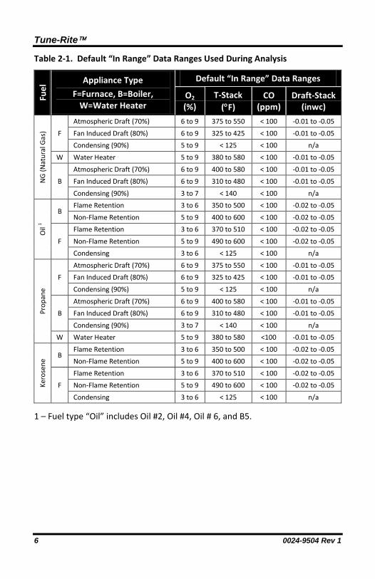
WARNING: The probable causes in the help screens are based on the appliance type and typical operating values. The operating values programmed in the analyzer are typical but not comprehensive. CO recommendations are based on 100 ppm CO. Local rules and regulations always take precedence. Where applicable, smoke tests (in fuel oil applications) and draft tests (for all fuels) should be performed prior to combustion tests. The operator should compare the appliance manufacturer’s operating values to the analyzer’s default values to ensure that analyzer results are applicable to the appliance under test. Review Table 2-1 for a list of default values used during the analysis.
Tune-Rite
6 0024-9504 Rev 1
Table 2-1. Default “In Range” Data Ranges Used During Analysis
Fuel
Appliance Type F=Furnace, B=Boiler,
W=Water Heater
Default “In Range” Data Ranges
O2 (%)
T-Stack (°F)
CO (ppm)
Draft-Stack (inwc)
NG
(Nat
ural
Gas
) F
Atmospheric Draft (70%) 6 to 9 375 to 550 < 100 -0.01 to -0.05
Fan Induced Draft (80%) 6 to 9 325 to 425 < 100 -0.01 to -0.05 Condensing (90%) 5 to 9 < 125 < 100 n/a
W Water Heater 5 to 9 380 to 580 < 100 -0.01 to -0.05
B Atmospheric Draft (70%) 6 to 9 400 to 580 < 100 -0.01 to -0.05 Fan Induced Draft (80%) 6 to 9 310 to 480 < 100 -0.01 to -0.05
Condensing (90%) 3 to 7 < 140 < 100 n/a
Oil
1
B Flame Retention 3 to 6 350 to 500 < 100 -0.02 to -0.05
Non-Flame Retention 5 to 9 400 to 600 < 100 -0.02 to -0.05
F
Flame Retention 3 to 6 370 to 510 < 100 -0.02 to -0.05
Non-Flame Retention 5 to 9 490 to 600 < 100 -0.02 to -0.05 Condensing 3 to 6 < 125 < 100 n/a
Prop
ane
F Atmospheric Draft (70%) 6 to 9 375 to 550 < 100 -0.01 to -0.05 Fan Induced Draft (80%) 6 to 9 325 to 425 < 100 -0.01 to -0.05
Condensing (90%) 5 to 9 < 125 < 100 n/a
B Atmospheric Draft (70%) 6 to 9 400 to 580 < 100 -0.01 to -0.05 Fan Induced Draft (80%) 6 to 9 310 to 480 < 100 -0.01 to -0.05
Condensing (90%) 3 to 7 < 140 < 100 n/a W Water Heater 5 to 9 380 to 580 <100 -0.01 to -0.05
Kero
sene
B Flame Retention 3 to 6 350 to 500 < 100 -0.02 to -0.05 Non-Flame Retention 5 to 9 400 to 600 < 100 -0.02 to -0.05
F Flame Retention 3 to 6 370 to 510 < 100 -0.02 to -0.05 Non-Flame Retention 5 to 9 490 to 600 < 100 -0.02 to -0.05
Condensing 3 to 6 < 125 < 100 n/a
1 – Fuel type “Oil” includes Oil #2, Oil #4, Oil # 6, and B5.

Tune-Rite
0024-9504 Rev 1 7
Section 3. Tune-Rite Basics
3.1. Supported Appliances and Fuel Types
The Fyrite INSIGHT Plus instrument is useful in analyzing the combustion process in a wide variety of applications. (For a complete list of features and applications, refer to your Fyrite INSIGHT Plus combustion analyzer manual.) Tune-Rite focuses exclusively on the appliance types listed below.
• Natural gas furnaces (atmospheric, fan induced and condensing) • Natural gas boilers (atmospheric, fan induced and condensing) • Oil boilers (retention and non-retention) • Oil furnaces (retention, non-retention and condensing) • Kerosene furnaces (retention, non-retention and condensing) • Kerosene boilers (retention and non-retention) • Propane furnaces (atmospheric, fan induced and condensing) • Propane boilers (atmospheric, fan induced and condensing) • Natural gas water heaters • Propane water heaters
NOTE: “Oil” includes Oil #2, Oil #4, Oil #6, and B5.
Refer to your Fyrite INSIGHT Plus manual for the locations of sampling points on your combustion appliance.
IMPORTANT: Review the appliance manufacturer’s recommendations for the combustion device being tested, and be aware of accepted practices of the local jurisdiction before introducing sampling holes into exhaust pipes or ducts.
WARNING: To prevent dangerous exhaust gases from leaking into the space, be sure to completely and securely seal any sampling holes made in the exhaust pipes or ducts.

Tune-Rite
8 0024-9504 Rev 1
3.2. Typical Combustion Process Review
In a typical combustion process (see Figure 3-1), the following steps usually take place:
• Initial light-off of the combustion appliance
• The system warms up to the point when a steady-state condition is reached. If steady-state is not reached, the combustion appliance may require major tuning, major repairs, or replacement.
• For oil-fired appliance, a smoke test is performed.
• A draft test is performed to verify proper draft in the system.
• Combustion variables (O2, CO, CO2, ambient temperature, stack temperature, etc.) are analyzed to determine efficiency and proper operation.
• Out-of-range values are indicative of less-than-optimal combustion, and may indicate hardware problems and even safety issues.
• Further investigation may occur and adjustments may be made to the combustion equipment.
• Combustion variables are re-evaluated.
• Additional adjustments may be made until the combustion appliance is operating within the appliance manufacturer’s recommended guidelines. If this state is never reached, major repairs may be required, the appliance manufacturer’s associated documentation may need to be referenced, or a full system replacement may be warranted.
Figu
re 3
-1.
Typi
cal C
ombu
stio
n An
alys
is F
low
char
t

Tune-Rite
0024-9504 Rev 1 9
Technology can be used to simplify this process. The Fyrite INSIGHT Plus combustion analyzer provides precise live readings of critical combustion data during this process. To determine if the combustion appliance is operating properly and within the appliance manufacturer’s recommended specifications, the HVAC technician must still refer to the following.
• Industry experience to evaluate the combustion data • Familiarity with the combustion appliance • Familiarity and understanding of the operation of the analyzer
3.3. The Tune-Rite Integration
Tune-Rite provides an integrated “when-you-need-it” solution that offers guidance based on live data and typical characteristics of the combustion appliance. It gives an additional layer of diagnostic thoroughness to the traditional combustion analysis process, while offering additional confidence to the service technician.
Figure 3-2. Accessing Tune-Rite™ from the Main Menu
WARNING: Be aware of operating limits associated with the combustion appliance you are analyzing. Tune-Rite provides general tuning and efficiency recommendations based on the type of appliance and fuel you are using (as well as combustion data). However, always follow the operating instructions and guidelines from the appliance manufacturer for details on precise operating limits.

Tune-Rite
10 0024-9504 Rev 1
Figure 3-3. Tune-Rite™ Process Map Integration

Tune-Rite
0024-9504 Rev 1 11
Figure 3-3. Tune-Rite™ Process Map Integration (Continued)

Tune-Rite
12 0024-9504 Rev 1
Section 4. Using Tune-Rite
4.1. Introduction
Using the Tune-Rite combustion analysis assistant is similar to using the Fyrite INSIGHT Plus combustion analyzer. If you are already familiar with the INSIGHT Plus, using the Tune-Rite feature will be very intuitive as the screens and menu structure are very similar. Below is a review of the basic menu navigation keys, which also apply to navigation within the Tune-Rite screens.
Table 4-1. Tune-Rite™ Menu Navigation Keys
Key Name Symbol General Navigation Function
Arrow Keys , , , Up, down, left, and right movement within a screen or between screens
Enter Key Proceed; perform the selected action
Escape Key ESC Go back
If you are new to using the Fyrite INSIGHT Plus, please refer to the INSIGHT Plus manual for details on combustion analyzer operating instructions, menus, complete navigation instructions, and important warnings.
Multiple fuel types, appliance types, and combustion readings could produce many Tune-Rite recommendations. This section shows only a small sampling of those options in order to familiarize the operator with Tune-Rite behavior and intuitive operation.
4.2. Selecting Fuel Type and Accessing Tune-Rite
Step Description
1 Turn on the Fyrite INSIGHT Plus combustion analyzer and wait for it to complete its initialization and warm-up procedure. Refer to the INSIGHT® Plus Instruction Manual P/N: 0024-9487 for details.

Tune-Rite
0024-9504 Rev 1 13
Step Description
2 From the Main Menu of the Fyrite INSIGHT Plus, select the Fuel option and press the Enter key ( ). This displays the Select Fuel menu.
3 From the list of fuel types in the Select
Fuel menu, select the fuel type for the combustion appliance you are testing (see Figure 4-1 below and Fuel Types on page 7).
4 From the Main Menu, use the up and
down arrow keys (,) to select the Tune-Rite option, then press the Enter key ( ).
5 Read and accept the disclaimer that is
displayed. If you selected a fuel that is unsupported by Tune-Rite, an error is displayed when you attempt to access Tune-Rite. Refer to Figure 4-2 below.
Figure 4-1. Fuel Selection Screens for Supported Fuel
Figure 4-2. Fuel Selection Screens for Unsupported Fuel

Tune-Rite
14 0024-9504 Rev 1
4.3. Furnace/Boiler Light-Off
If the combustion appliance you are testing is new or is shut off (i.e., “cold”), be sure to start the appliance according to the appliance manufacturer’s instructions so that it can warm-up and the process can begin to reach steady-state conditions (which usually takes about 5-10 minutes).
4.4. Sample Smoke Test (Oil-Fired Appliances Only)
If the combustion appliance you are testing uses oil as a fuel, it is important to perform a smoke test. Excessive smoke from oil combustion is indicative of a serious combustion process problem, and can also be harmful to people and bad for sensitive combustion analysis equipment like the INSIGHT Plus. A smoke test is used to ensure that the oil-fired system is at least adequately “coarsely” tuned to warrant finer detailed tuning using the combustion analyzer.
A smoke test is a mechanical test that samples the combustion gas by drawing it through a white paper filter. Visual comparison of the combustion gas residue against standard smoke level samples shows the operator if the combustion system is significantly out of tune and in need of coarse tuning before the combustion analyzer should be used.
Step Description
1 After setting the fuel type (oil) and accepting the disclaimer, select the oil boiler type and press Enter ( ). • Boiler with flame retention burner
head (>80% efficient) • Boiler with non-flame retention
burner head (<75% efficient)
2 Select Smoke Number from the Analyze menu and press Enter ( ). The Smoke Number screen is displayed and a Smoke Number is requested.

Tune-Rite
0024-9504 Rev 1 15
Step Description
3 Use a True Spot Smoke Tester to sample the oil burners’ combustion gas. Compare the sample with the smoke chart to determine the smoke number.
4 Enter the oil burner’s smoke number. Based on the smoke number value that you enter, you may be asked if oil is seen on the paper, to which you will enter either Yes or No.
5 Tune-Rite results are displayed. In
this case a “Smoke High” result is displayed. Press Enter ( ) to see the checklist of possible items to check for a high smoke condition.
6 Review the checklist using the up and down arrow keys (,) to navigate through the list.
7 Inspect, adjust, and/or repair the
appliance based on safety guidelines, local regulations, the appliance manufacturer’s recommendations, and system guidance from Tune-Rite™. Refer to INSIGHT® Plus Instruction Manual for further safety details.
8 As you inspect, repair, and adjust the
combustion appliance, track your progress by cycling through options using the Enter key ( ). Refer to Figure 4-3 below.

Tune-Rite
16 0024-9504 Rev 1
Figure 4-3. Cycling Through Tracking Options
Step Description
9 Press the Back key (F2) to go back to the results screen. Then press the Analyze key (F3) to re-analyze.
10 Select the Smoke Number option from
the Analyze menu. The Smoke Number screen is displayed and a Smoke Number is requested.
11 Use a True Spot Smoke Tester to
sample the oil burners’ combustion gas. Compare the sample with the smoke chart to determine the smoke number.
12 Enter the oil burner’s new smoke number after repairs and adjustments have been made.
13 Check the smoke test paper for signs of
oil residue and enter the appropriate response.
Tune-Rite
0024-9504 Rev 1 17
Step Description
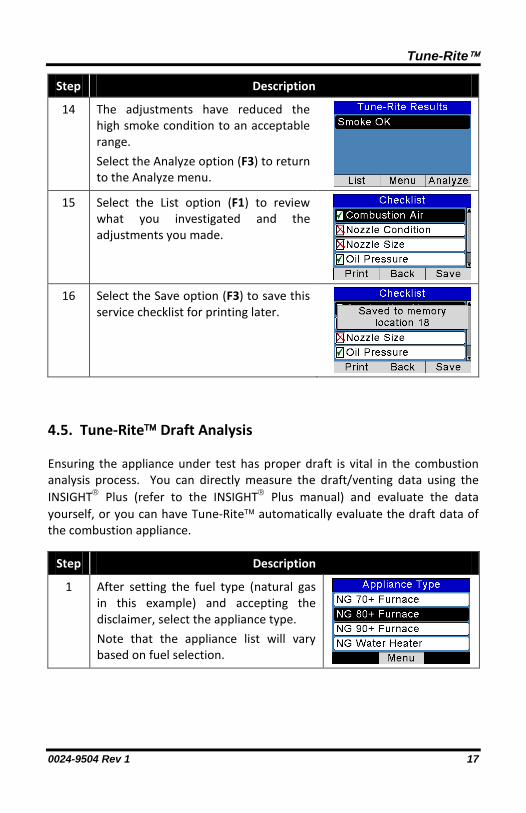
14 The adjustments have reduced the high smoke condition to an acceptable range. Select the Analyze option (F3) to return to the Analyze menu.
15 Select the List option (F1) to review what you investigated and the adjustments you made.
16 Select the Save option (F3) to save this
service checklist for printing later.
4.5. Tune-Rite Draft Analysis
Ensuring the appliance under test has proper draft is vital in the combustion analysis process. You can directly measure the draft/venting data using the INSIGHT Plus (refer to the INSIGHT Plus manual) and evaluate the data yourself, or you can have Tune-Rite automatically evaluate the draft data of the combustion appliance.
Step Description
1 After setting the fuel type (natural gas in this example) and accepting the disclaimer, select the appliance type. Note that the appliance list will vary based on fuel selection.

Tune-Rite
18 0024-9504 Rev 1
Step Description
2 Select the draft option from the Analyze menu. Note that the number of options in this screen and their names will vary based on the selected fuel type and appliance type.
3 A steady-state reminder message is
displayed. Be sure that a steady-state condition is reached before taking venting or draft measurements.
4 The draft measurement from the
INSIGHT Plus is displayed.
5 Press the Enter key ( ) to analyze
using Tune-Rite.
6 Tune-Rite results are displayed. Press Next (F2) to see the Tune-Rite Results screen.
7 Press the Save key (F3) to save draft
data (to be used as your “as found” draft data when you build your service checklist and report).
8 In this case, a “Draft Low” message is
displayed. Press Enter ( ) to see the list of possible causes for this condition.

Tune-Rite
0024-9504 Rev 1 19
Step Description
9 Review the list of possible causes. Note that the list may scroll off the screen, so you may need to use the arrow keys (,) to navigate through the list.
10 Inspect, adjust, and/or repair the
appliance based on safety guidelines, local regulations, the appliance manufacturer’s recommendations, and system guidance from Tune-Rite™. Refer to INSIGHT® Plus Instruction Manual for further safety details.
11 As you inspect, repair, and adjust the
combustion appliance, track your progress by cycling through options using the Enter key ( ). Refer to Figure 4-3 on page 16.
12 Go back and re-analyze. Select the Draft option from the Analyze menu and press the Enter key ( ).
13 The updated draft measurement from
the INSIGHT Plus is displayed.
14 Press the Save key (F3) to save this draft
data (to be used as your “as left” draft data when you build your service checklist and report).
15 Press the Enter key ( ) to re-analyze
using Tune-Rite.

Tune-Rite
20 0024-9504 Rev 1
Step Description
16 The adjustments have corrected the low draft condition. The draft reading is now within an acceptable range.
17 Select the List option (F1) to review
what you investigated and the adjustments you made.
18 Select the Save option (F3) to save this
service checklist for printing later.
4.6. Tune-Rite Combustion Analysis
You can directly measure combustion data using the INSIGHT Plus (refer to the INSIGHT Plus manual) and evaluate the results yourself, or you can have Tune-Rite automatically analyze the combustion data and make recommendations for repairs and any appropriate optimization.
IMPORTANT: Possible cause recommendations and range-of-operation values provided during combustion analysis testing assume the combustion appliance is running in high-fire mode.

Tune-Rite
0024-9504 Rev 1 21
Step Description
1 After setting the fuel type (Natural gas in this example) and accepting the disclaimer (F3), select the appliance type from the list and press Enter ( ). Note that the appliance list will vary based on the selected fuel.
2 Select the Combustion option from the
Analyze menu and press Enter ( ) to initiate the analysis. Note that the number of options in this screen and their names will vary based on the selected fuel type and appliance type.

Tune-Rite
22 0024-9504 Rev 1
Step Description
3 The high-fire reminder message Appliance must be in high-fire. and the steady-state reminder message Waiting for steady-state. are displayed briefly. In addition, the red dot () in the upper right portion of the screen indicates that combustion readings have not yet reached a steady-state condition. If you attempt to initiate a Tune-Rite™ combustion analysis (by pressing the Enter key ) before steady state is reached, an Insufficient Wait Time message is displayed briefly. (Note that this popup indicates that the analyzer has insufficient data to make a steady-state determination – unlike the similar terminology in the Results screen which relates to the appliance wait time.) Similarly, if you attempt to initiate a Tune-Rite™ combustion analysis with a combustion oxygen level above 16%, a message is displayed to warn you that the analyzer’s probe may not be connected: O2 above 16%. Is probe connected? . NOTE: Remember that ambient “air” contains approximately 21% O2. Flue gas usually contains less than 16% O2. So, your analyzer will not perform a combustion analysis (or an efficiency calculation, or a number of other calculations) until the O2 reading is 16% or lower.

Tune-Rite
0024-9504 Rev 1 23
Step Description
4 Press the left and right arrow keys (,) to scroll through different display types. As combustion readings begin to reach steady state condition, you may notice that those readings will begin to settle into stable values. Though individual values may be stable (that is, they are no longer displayed with a yellow pointer [ ] on the dynamic graph display), they may or may not be within the acceptable operating range for the selected fuel and appliance type (green pointer [ ] for within range, red pointer [ ] for outside the acceptable range).
5 After a sufficient wait time has elapsed and after Tune-Rite confirms the stability of all combustion parameters, the round steady-state dot changes from red () to green (). Notice that the previously unstable CO reading (yellow pointer ) has changed to a red pointer ( ), indicating stability, but an operating range that is not acceptable (similar to the T-Stack value, which is also out of range in this example).
6 Press the Enter key ( ) to analyze the combustion data using Tune-Rite.
7 An Analyzing… message is displayed temporarily showing that Tune-Rite™ is analyzing the combustion data to determine possible causes for the out-of-range conditions.

Tune-Rite
24 0024-9504 Rev 1
Step Description
8 When the analysis is complete, the Analyzing… message disappears, and the bar graph summary screen is displayed. Press the Save key (F3) to save this steady-state snapshot (“as found” data) for use later in the custom report to show the conditions before any corrective actions were performed.
9 From the Tune-Rite Summary screen,
press the Next key (F2) to show the Tune-Rite Results screen. It provides a prioritized list of possible causes for the out-of-range conditions. Possible causes may span several screens (as indicated by the scroll bar on right side of the display).
10 Use the up and down arrow keys (,)
to highlight the possible cause that you want to investigate. Press the Enter key ( ) to get a prioritized checklist of items to inspect and evaluate.

Tune-Rite
0024-9504 Rev 1 25
Step Description
11 Checklist items may span several screens (as indicated by the scroll bar on right side of the display). Use the up and down arrow keys (,) to highlight the current checklist item under investigation.
12 Press the
Info key (F3) to get a brief description of the highlighted checklist item. Press Back (F1) to return.

Tune-Rite
26 0024-9504 Rev 1
Step Description
13 Inspect, adjust, and/or repair the appliance based on safety guidelines, local regulations, the appliance manufacturer’s recommendations, and system guidance from Tune-Rite™. Refer to the INSIGHT® Plus Instruction Manual for further safety details. As you inspect, evaluate, and repair the appliance, track your progress through the checklist. For each item selected, press the Enter key ( ) repeatedly to cycle through three evaluation options:
Not Investigated
Checked/Okay Adjusted/Repaired
14 After making adjustments and/or repairs, press the Back key (F2) to return to the Tune-Rite Results screen.
15 Press the Analyze key (F3) to re-analyze
the combustion process to see the effects of the repairs and adjustments. Use the arrow keys (,) to highlight Combustion, and then press Enter ( ) to start the combustion analysis again.
16 As before, the analyzer will ensure that combustion values have reached steady state after your adjustments and/or repairs. The Waiting for steady-state. message is displayed

Tune-Rite
0024-9504 Rev 1 27
Step Description
17 As the combustion appliance reaches steady state, the status dot will change from red () to green (). In this example, note that the combustion values all appear to be within recommended ranges, therefore the pointers are all shown in green ( ), i.e., within range, after steady state is reached.
18 With repairs completed and combustion
values within acceptable ranges, press the Save key (F3) to save this steady-state snapshot (“as left” data) for use later in the service checklist to show the conditions after adjustments were performed.
19 Press the Next key (F2) to show the new Tune-Rite™ results from the adjustments that were made. Tune-Rite™ confirms that combustion readings are within range.
20 Press the List key (F1) to view the
combustion checklist. Use the up and down arrows (,) to view the entire list.

Tune-Rite
28 0024-9504 Rev 1
Step Description
21 Press the Save key (F3) to save the checklist for use later to show what investigations were made and what corrective actions were performed. Then press the Back key (F2) to return to the Menu. NOTE: Checklist tracking marks remain active until you exit Tune-Rite™. Tracking marks are only cancelled when you exit Tune-Rite™.
4.7. Custom Reporting
Prepare for your final report: You should record data throughout the troubleshooting process for use later in the reporting phase.
Step Description
1 Select the Memory option from the Main Menu and press Enter ( ).
2 Use the arrow keys (,) to select the
Print Report option, and then press Enter ( ).
3 Using the up and down arrow keys
(,), select the desired “As Found” combustion item then press Enter ( ) to view that record’s data to confirm. Use the date/time stamp and the record’s suffix to identify the desired record to add (L=checklist data, C=combustion record, T=temperature data, and P=pressure data).

Tune-Rite
0024-9504 Rev 1 29
Step Description
4 Review the combustion data as the correct “As Found” data, then press the Add key (F3) to add that “As Found” record to the print report, or press Back (F1) to select a different combustion record for the report.
5 Using the up and down arrow keys (,), select the desired “As Left” combustion item then press Enter ( ) to view that record’s data to confirm.
6 Review the combustion data as the
correct “As Left” data, then press the Add key (F3) to add that “As Left” record to the print report, or press Back (F1) to select a different combustion record for the report.
7 Using the up and down arrow keys
(,), select the desired Checklist record then press Enter ( ) to view that checklist to confirm. Press the Skip key (F2) to create a report without the checklist.
8 Review the checklist to confirm it is the correct one (you may have saved other checklists in the analyzer’s memory), then press the Add key (F3) to add that checklist to the print report, or press Back (F1) to select a different checklist for the report.

Tune-Rite
30 0024-9504 Rev 1
Step Description
9 Turn on and align your printer, then press Enter ( ) to print the final report. A sample printout is shown in Figure 4-4. Note that the sample printout does not reflect all of the sample screens shown in this section. Your printout will reflect the data you save and the records you choose for your printout.
Figure 4-4. Sample Printout Showing Service Checklist

Tune-Rite
0024-9504 Rev 1 31
Section 5. Reference, Service, and Support
Refer to the following documents for additional reference material about the Fyrite INSIGHT Plus, Tune-Rite, and combustion process terminology. On the web, visit www.Tune-Rite.com.
Table 5-1. Reference Material Part Numbers
Reference Material Title Part Number
Tune-Rite Quick Start Guide 0024-9505
Tune-Rite Reference Guide and Glossary 0024-9507
True-Spot Smoke Tester Instructions and Parts List 0021-9012
Fyrite INSIGHT Plus Instruction Manual 0024-9487
Service and technical support can be obtained by contacting one of the following Bacharach Service Centers.
Location Contact Information Service Shipping Address
United States
www.mybacharach.com/rmaform/ Phone: 724-334-5000 Toll Free: 1-800-736-4666 Fax: 724-334-5001
Bacharach, Inc. 621 Hunt Valley Circle
New Kensington, PA 15068 ATTN: Service Department
Ireland Phone: +353 1 284 6388 Fax: +353 1 284 6389
Murco Ltd – A Bacharach Company 114A Georges Street Lower
Dun Laoghaire, Dublin, Ireland ATTN: Service Department
Canada Phone: 905-470-8985 Fax: 905-470-8963 Email: [email protected]
Bacharach Of Canada 20 Amber Street Unit #7
Markham, Ontario L3R 5P4 ATTN: Service Department
∇ ∇ ∇

Tune-Rite
32 0024-9504 Rev 1
World Headquarters 621 Hunt Valley Circle, New Kensington, Pennsylvania 15068
Phone: 724-334-5000 • Toll Free: 1-800-736-4666 • Fax: 724-334-5001 Website: www.MyBacharach.com • E-mail: [email protected]
-*-