Embed Size (px)
Citation preview
Tunable 10Gb/s ROSA for NG-PON2
1. INTRODUCTION
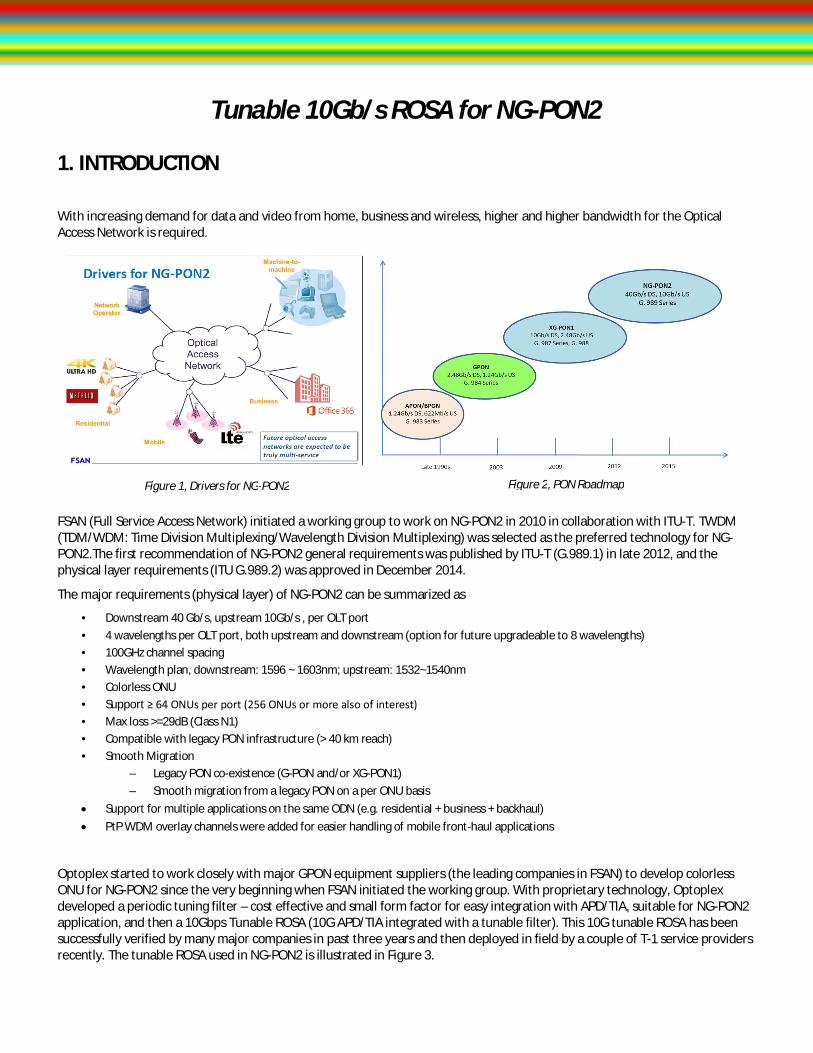
With increasing demand for data and video from home, business and wireless, higher and higher bandwidth for the Optical Access Network is required.
FSAN (Full Service Access Network) initiated a working group to work on NG-PON2 in 2010 in collaboration with ITU-T. TWDM (TDM/WDM: Time Division Multiplexing/Wavelength Division Multiplexing) was selected as the preferred technology for NG-PON2.The first recommendation of NG-PON2 general requirements was published by ITU-T (G.989.1) in late 2012, and the physical layer requirements (ITU G.989.2) was approved in December 2014.
The major requirements (physical layer) of NG-PON2 can be summarized as
• Downstream 40 Gb/s, upstream 10Gb/s , per OLT port • 4 wavelengths per OLT port, both upstream and downstream (option for future upgradeable to 8 wavelengths) • 100GHz channel spacing • Wavelength plan, downstream: 1596 ~ 1603nm; upstream: 1532~1540nm • Colorless ONU • Support ≥ 64 ONUs per port (256 ONUs or more also of interest) • Max loss >=29dB (Class N1) • Compatible with legacy PON infrastructure (> 40 km reach) • Smooth Migration
– Legacy PON co-existence (G-PON and/or XG-PON1) – Smooth migration from a legacy PON on a per ONU basis
Support for multiple applications on the same ODN (e.g. residential + business + backhaul) PtP WDM overlay channels were added for easier handling of mobile front-haul applications
Optoplex started to work closely with major GPON equipment suppliers (the leading companies in FSAN) to develop colorless ONU for NG-PON2 since the very beginning when FSAN initiated the working group. With proprietary technology, Optoplex developed a periodic tuning filter – cost effective and small form factor for easy integration with APD/TIA, suitable for NG-PON2 application, and then a 10Gbps Tunable ROSA (10G APD/TIA integrated with a tunable filter). This 10G tunable ROSA has been successfully verified by many major companies in past three years and then deployed in field by a couple of T-1 service providers recently. The tunable ROSA used in NG-PON2 is illustrated in Figure 3.
Figure 1, Drivers for NG-PON2 Figure 2, PON Roadmap

Optoplex Corporation, 3374 Gateway Boulevard, Fremont, CA 94538, USA. Tel: (510) 490–9930, Fax: (510) 490–9330, www.optoplex.com, [email protected]
OptoplexC O R P O R A T I O N
TMOptoplexC O R P O R A T I O N
TM
C O R P O R A T I O N
TM
Features Applications
100GHz tunable filter with tuning range of 4 channels
InGaAs APD for 10Gbps High gain 12k transimpedance pre-amplifier Differential data output High sensitivity: < -28dBm Low power consumption: < 0.4W
Digital fiber optic receiver for access networks for telecom
High speed optical data networks Fiber in the loop (FTTx) SFP+/XFP/300pin MSA optical transceiver
Figure 3, 10Gb/s Tunable ROSA for colorless ONU in NG-PON2
Figure 4, Optoplex’s 10G Tunable ROSA for NG-PON2

Optoplex Corporation, 3374 Gateway Boulevard, Fremont, CA 94538, USA. Tel: (510) 490–9930, Fax: (510) 490–9330, www.optoplex.com, [email protected]
OptoplexC O R P O R A T I O N
TMOptoplexC O R P O R A T I O N
TM
C O R P O R A T I O N
TM
2. ABSOLUTE MAXIMUM RATINGS
3. OPERATING CONDITIONS
NOTES 1. Short term refers to the operation of the device for a period of less than 100 hours per year.
Item Parameter Symbol Condition Min Max Unit
1 Storage temperature range Tstg -40 75 °C
2 Storage humidity RHstg Non Condensing 5 85 %
3 Maximal optical input power Popt-max
Continuous wave on input port -26 -5 dBm
4 TIA supply voltage VCC -0.7 5 V
5 APD supply Voltage VPD 0 VBR V
6 APD reverse current IR 2 mA
7 Tunable Filter Driving voltage VTF DC 4.0 V
Item Parameter Unit Condition Min Typ. Max
1 Operating case temperature range 1) °C -5 75
2 Relative humidity range % 5 85
3 Operating frequency range THz C- Band 191.15 196.1
4 Optical input power dBm -26 -5
5 TIA supply voltage V 3.0 3.3 3.6
6 TIA supply current mA Pin=0 uA 40 55 70
7 Tunable Filter Driving voltage V DC 0 3.8

Optoplex Corporation, 3374 Gateway Boulevard, Fremont, CA 94538, USA. Tel: (510) 490–9930, Fax: (510) 490–9330, www.optoplex.com, [email protected]
OptoplexC O R P O R A T I O N
TMOptoplexC O R P O R A T I O N
TM
C O R P O R A T I O N
TM
4.ProductDescription
Figure 4.1 Functional block diagram of 10G Tunable ROSA
5.TunableFilterSpecifications
5.1, Functional Block Diagram of Tunable Filter
Figure 5.1 Functional block diagram of Tunable filter inside
Description:
λx (x=1 to 4): The output of the tunable filter can be any channel of the input selected by input voltage.

Optoplex Corporation, 3374 Gateway Boulevard, Fremont, CA 94538, USA. Tel: (510) 490–9930, Fax: (510) 490–9330, www.optoplex.com, [email protected]
OptoplexC O R P O R A T I O N
TMOptoplexC O R P O R A T I O N
TM
C O R P O R A T I O N
TM
5.2, Specification of Tunable Filter
Table 5.1 Tunable Filter Specification
Item Parameter Comments Min Type Max Unit
1 Operating wavelength range 1) 1600 1625 nm
2 Tunable Filter Insertion loss 2.5 dB
3 Wavelength Tuning range2) -5 to 75 450 GHz
4 Filter Pass Band Width @1dB 20
GHz @20dB 150
5 Optical return loss 27 dB
6 PDL 0.8 dB
7 Tuning speed From channel i to i+1 1 s
8 Thermistor resistance 10 k
9 TF Tuning Voltage 3.8 V
10 Voltage Dependent Loss 0.5 1 dB
Notes 1) 1600 ~ 1625nm is the required operating wavelength for the 4 TWDM channels of NGPON2. Optoplex tunable filter
can work in a much wider wavelength range from 1500 ~ 1650nm 2) The maximum working temperature of wavelength tuner is 120°C.
5.3, Control of Tunable Filter

Optoplex Corporation, 3374 Gateway Boulevard, Fremont, CA 94538, USA. Tel: (510) 490–9930, Fax: (510) 490–9330, www.optoplex.com, [email protected]
OptoplexC O R P O R A T I O N
TMOptoplexC O R P O R A T I O N
TM
C O R P O R A T I O N
TM
6.10GROSASpecifications
6.1, Optical Characteristics Item Parameter Comments Min Type Max Unit
1 Operating wavelength range 1525 1565 nm
2 Responsivity M=1, CW 0.75 A/W
3 Responsivity with filter M=1, CW 0.42 A/W
4 Minimum Sensitivity 10.3Gbps, RL=50Ω, BER=1×10-
3, NRZ, ER=6.42 dB, PRBS=231-1 , Mopt, λ=1550nm
-30.5 dBm
4 Optical return loss 27 dB
6.2, Electrical Characteristics
Table 6.2 Electrical Specification
Item Parameter Comments Min Type Max Unit
1 TIA supply voltage VCC 3 3.3 3.6 V
2 TIA supply current Pin=0uW 40 55 70 mA
3 Operating Voltage VOP, M=MOPT; 0.9×Vbr V
4 Trans-impedance F=200MHz, RL=50Ω, Pin=1Uw, M=10, differential
2.0 K
5 3dB bandwidth @-3dB, M=10,RL=50Ω Pin=-20dBm 6.0 GHz
6 Temperature coefficient of VBR Id=10uA, TC=25~75ºC 0.03 V/℃
7 Breakdown voltage Dark current Id=10uA 25 34 40 V

Optoplex Corporation, 3374 Gateway Boulevard, Fremont, CA 94538, USA. Tel: (510) 490–9930, Fax: (510) 490–9330, www.optoplex.com, [email protected]
OptoplexC O R P O R A T I O N
TMOptoplexC O R P O R A T I O N
TM
C O R P O R A T I O N
TM
6.3, Measured S-Parameters
Input power -20dBm Input power -25dBm
Input power -30dBm Input power -35dBm

Optoplex Corporation, 3374 Gateway Boulevard, Fremont, CA 94538, USA. Tel: (510) 490–9930, Fax: (510) 490–9330, www.optoplex.com, [email protected]
OptoplexC O R P O R A T I O N
TMOptoplexC O R P O R A T I O N
TM
C O R P O R A T I O N
TM
7. Physical Properties
7.1, Mechanical Drawings
Figure 7.1 Mechanical model of the integrated receiver
7.2, Electrical Interface

Optoplex Corporation, 3374 Gateway Boulevard, Fremont, CA 94538, USA. Tel: (510) 490–9930, Fax: (510) 490–9330, www.optoplex.com, [email protected]
OptoplexC O R P O R A T I O N
TMOptoplexC O R P O R A T I O N
TM
C O R P O R A T I O N
TM
Figure 7.2 Illustration of pin assignment
Table 7.1 PIN Assignment
Pin# Name Description
1 NA
2 VCC TIA supply voltage
3 Signal Ground
4 Out
5 Out-ber
6 Signal Ground
7 NA
8 VAPD
9 Tuner
10 Tuner
11 Thermistor
12 Thermistor
VAPD
GND
VOUT
VOUT
VCC
APD
TIA

Optoplex Corporation, 3374 Gateway Boulevard, Fremont, CA 94538, USA. Tel: (510) 490–9930, Fax: (510) 490–9330, www.optoplex.com, [email protected]
OptoplexC O R P O R A T I O N
TMOptoplexC O R P O R A T I O N
TM
C O R P O R A T I O N
TM
7.3, Optical input Specification
Table 7.2 input beam specification
Input beam Parameter Unit Value Notes
Collimated beam diameter mm 0.5-1 Measure at 1/e2 .This parameter will influence the Responsivity.
Collimated beam waist position mm TBD From the front surface. This parameter will influence the Responsivity.
Incident angle degree <3 The angel between input beam and normal of the front surface. This parameter will influence the Responsivity.
7.4, Label Specification TBD.
8.OrderingInformation
Product: Tunable 10G ROSA
Product Description: 10G Tunable ROSA, APD/TIA, C-band, 100GHz Channel Spacing, 400GHz Tuning Range, LC/UPC Connector
Part Number: RX-2C2RT701
9.ContactInformation
Optoplex Corporation 3374 Gate Boulevard Fremont, CA 94538 USA Tel: (510) 490-9930 Fax: (510) 490-9330 www.optoplex.com [email protected]
Sales
[email protected] Technical Support