Embed Size (px)
Citation preview
www.alliancelaundry.com
START25C
HIGHTEMP
MEDTEMPLOWTEMP
NOHEAT
1
2
3
SELECTTEMP
INSERTCOIN
PUSHSTART
T463PE1A
Tumble Dryers25 Pound (220 liter)
30 Pound Stack (300 liter)30 Pound (270 liter)35 Pound (350 liter)
Refer to Page 5 for Model Numbers
Part No. 70143101R3November 2016
Service

70143101 1
© Copyright 2016, Alliance Laundry Systems LLC
All rights reserved. No part of the contents of this book may be reproduced or transmitted in any form or by any means without the expressed written consent of the publisher.
© Copyright, Alliance Laundry Systems LLC – DO NOT COPY or TRANSMIT
Table of ContentsSection 1 –Safety Information
Locating An Authorized Service Person..................4
Section 2 –IntroductionModel Identification.................................................5Replacement Parts Information................................6Wiring Diagram .......................................................6Nameplate Location .................................................7How Your Tumble Dryer Works .............................8
Section 3 –Troubleshooting1. Tumble dryer does not start ...............................92. Motor does not start ...........................................93. Motor overload protector cycles repeatedly ....104. Motor runs but cylinder does not turn .............105. Motor does not stop .........................................106. Burner does not ignite......................................117. Burner ignites and goes out repeatedly............128. Burner does not shut off ..................................129. Clothes do not dry............................................13
10. Tumble dryer overheating................................1311. Burners not burning properly...........................1412. Cylinder door opens during operation .............14
Section 4 –GroundingGrounding Instructions ..........................................15
Section 5 –Service Procedures13. Loading door assembly....................................1714. Door hinge .......................................................1715. Door handle .....................................................1716. Front panel .......................................................1817. Door switch (All Models) ................................2018. Control and coin drop assembly ......................2219. Lint panel/drawer.............................................2320. Lint screen .......................................................2321. Lint drawer seal ...............................................2322. Lint drawer/panel switch .................................2423. Junction box/Control Box................................2524. Fuse and fuse holder assembly ........................2525. Cylinder rollers ...............................................2626. Roller shaft.......................................................2627. Cylinder and bearing assembly........................2728. Cylinder idler ...................................................2829. Cylinder seals...................................................30
30. Roller support and baffle assembly .................3131. Airflow switch .................................................3232. Stove high limit thermostat..............................3333. Complete gas valve assembly..........................3434. Burner tube assembly ......................................3635. Viewer window................................................3636. Igniter assembly...............................................3637. Electronic ignition control ...............................3738. Thermistor .......................................................3939. Cabinet thermostat ...........................................4040. Heater element .................................................4141. Contactors and terminal block .........................4242. Steam coil ........................................................4343. Steam solenoid valve .......................................4344. Drive belt .........................................................4445. Fan ...................................................................4646. Fan motor assembly.........................................4747. Drive motor......................................................48
Section 6 –Adjustments48. Leveling legs....................................................5149. Airflow switch adjustment...............................5150. Cylinder door switch .......................................5251. Troubleshooting and cleaning coin drop .........5452. Troubleshooting coin drop...............................5453. Cleaning coin drop...........................................54
Section 7 –Special Tools ......................................57

2 70143101© Copyright, Alliance Laundry Systems LLC – DO NOT COPY or TRANSMIT
70143101 3© Copyright, Alliance Laundry Systems LLC – DO NOT COPY or TRANSMIT
Section 1Safety Information
Throughout this manual and on machine decals, you will find precautionary statements (“CAUTION”, “WARNING”, and “DANGER”) followed by specific instructions. These precautions are intended for the personal safety of the operator, user, servicer, and those maintaining the machine.
DANGER
Danger indicates the presence of a hazard that will cause severe personal injury, death, or substantial property damage if the danger is ignored.
WARNING
Warning indicates the presence of a hazard that can cause severe personal injury, death, or substantial property damage if the warning is ignored.
CAUTION
Caution indicates the presence of a hazard that will or can cause minor personal injury or property damage if the caution is ignored.
Additional precautionary statements (“IMPORTANT” and “NOTE”) are followed by specific instructions.
IMPORTANT
The word “IMPORTANT” is used to inform the reader of specific procedures where minor machine damage will occur if the procedure is not followed.
NOTE
The word “NOTE” is used to communicate installation, operation, maintenance or servicing information that is important but not hazard related.
In the interest of safety, some general precautions relating to the operation of this machine follow.
• Failure to install, maintain and/or operate this product according to the manufacturer’s instructions may result in conditions which can produce serious injury, death and/or property damage.
• Do not repair or replace any part of the product or attempt any servicing unless specifically recommended or published in this Service Manual and unless you understand and have the skills to carry out the servicing.
• Whenever ground wires are removed during servicing, these ground wires must be reconnected to ensure that the product is properly grounded and to reduce the risk of fire, electric shock, serious injury or death.
W006R2
WARNING
4 70143101
Section 1 Safety Information
© Copyright, Alliance Laundry Systems LLC – DO NOT COPY or TRANSMIT
IMPORTANT INFORMATION: During the lifetime of your tumble dryer, it may require service. The information contained in this manual was written and is intended for use by qualified service technicians who are familiar with the safety procedures required in the repair of your tumble dryer, and who are equipped with the proper tools and testing equipment.
NOTE: The WARNING and IMPORTANT instructions appearing in this manual are not meant to cover all possible conditions and situations that may occur. It must be understood that common sense, caution and carefulness are factors which CANNOT be built into this tumble dryer. These factors MUST BE supplied by the person(s) installing, maintaining or operating the tumble dryer.
Always contact your dealer, distributor, service agent or the manufacturer on any problems or conditions you do not understand.
Locating An Authorized Service Person
Alliance Laundry Systems is not responsible for personal injury or property damage resulting from improper service. Review all service information before beginning repairs.
Warranty service must be performed by an authorized technician, using authorized factory parts. If service is required after the warranty expires, Alliance Laundry Systems also recommends contacting an authorized technician and using authorized factory parts.
To reduce the risk of electric shock, fire, explosion, serious injury or death:• Disconnect electric power to the tumbler before servicing.• Never start the tumbler with any guards/panels removed.• Whenever ground wires are removed during servicing, these ground wires must be
reconnected to ensure that the tumbler is properly grounded.W240
WARNING
Repairs that are made to your products by unqualified persons can result in hazards due to improper assembly or adjustments subjecting you or the inexperienced person making such repairs to the risk of serious injury, electrical shock or death.
W007
WARNING
If you or an unqualified person perform service on your product, you must assume the responsibility for any personal injury or property damage which may result. The manufacturer will not be responsible for any injury or property damage arising from improper service and/or service procedures.
W008
CAUTION
70143101 5© Copyright, Alliance Laundry Systems LLC – DO NOT COPY or TRANSMIT
Section 2Introduction
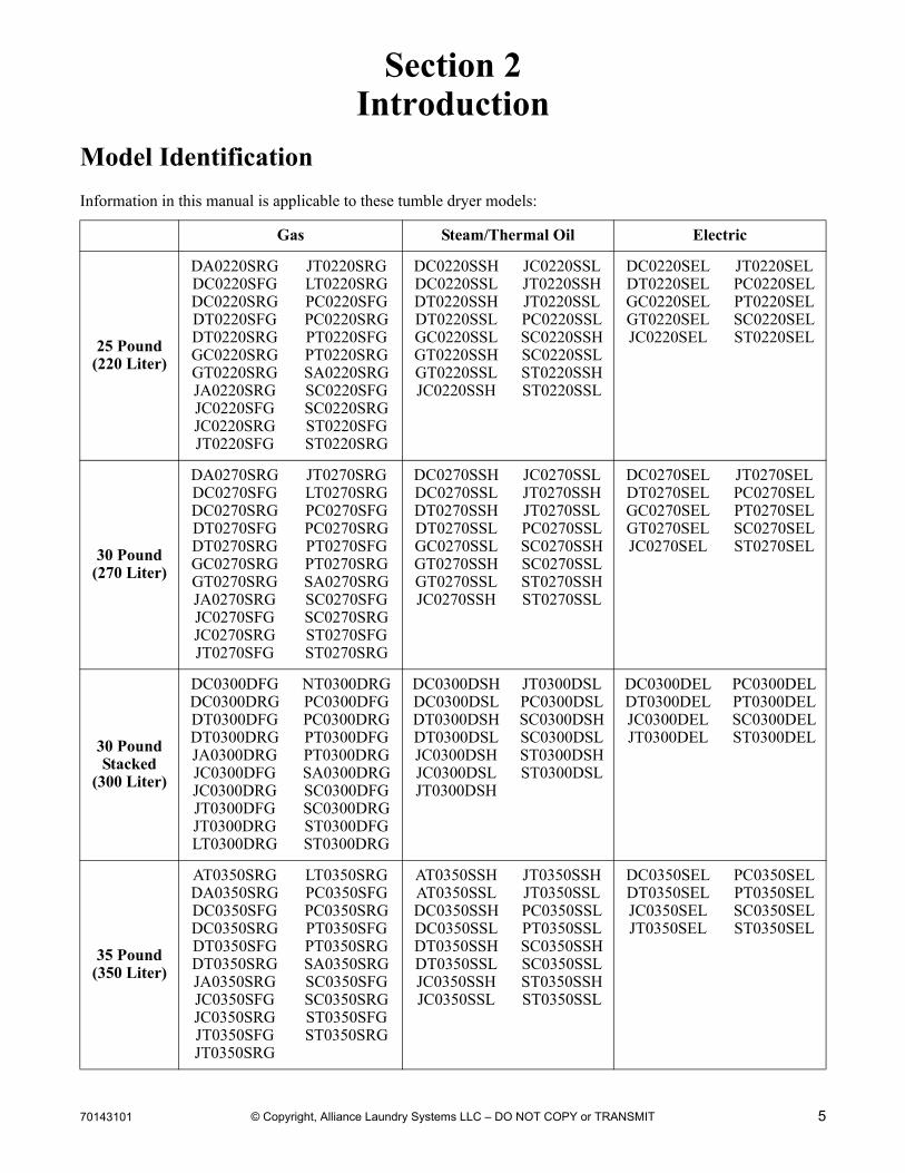
Model Identification
Information in this manual is applicable to these tumble dryer models:
Gas Steam/Thermal Oil Electric
25 Pound(220 Liter)
DA0220SRGDC0220SFGDC0220SRGDT0220SFGDT0220SRGGC0220SRGGT0220SRGJA0220SRGJC0220SFGJC0220SRGJT0220SFG
JT0220SRGLT0220SRGPC0220SFGPC0220SRGPT0220SFGPT0220SRGSA0220SRGSC0220SFGSC0220SRGST0220SFGST0220SRG
DC0220SSHDC0220SSLDT0220SSHDT0220SSLGC0220SSLGT0220SSHGT0220SSLJC0220SSH
JC0220SSLJT0220SSHJT0220SSLPC0220SSLSC0220SSHSC0220SSLST0220SSHST0220SSL
DC0220SELDT0220SELGC0220SELGT0220SELJC0220SEL
JT0220SELPC0220SELPT0220SELSC0220SELST0220SEL
30 Pound(270 Liter)
DA0270SRGDC0270SFGDC0270SRGDT0270SFGDT0270SRGGC0270SRGGT0270SRGJA0270SRGJC0270SFGJC0270SRGJT0270SFG
JT0270SRGLT0270SRGPC0270SFGPC0270SRGPT0270SFGPT0270SRGSA0270SRGSC0270SFGSC0270SRGST0270SFGST0270SRG
DC0270SSHDC0270SSLDT0270SSHDT0270SSLGC0270SSLGT0270SSHGT0270SSLJC0270SSH
JC0270SSLJT0270SSHJT0270SSLPC0270SSLSC0270SSHSC0270SSLST0270SSHST0270SSL
DC0270SELDT0270SELGC0270SELGT0270SELJC0270SEL
JT0270SELPC0270SELPT0270SELSC0270SELST0270SEL
30 PoundStacked
(300 Liter)
DC0300DFGDC0300DRGDT0300DFGDT0300DRGJA0300DRGJC0300DFGJC0300DRGJT0300DFGJT0300DRGLT0300DRG
NT0300DRGPC0300DFGPC0300DRGPT0300DFGPT0300DRGSA0300DRGSC0300DFGSC0300DRGST0300DFGST0300DRG
DC0300DSHDC0300DSLDT0300DSHDT0300DSLJC0300DSHJC0300DSLJT0300DSH
JT0300DSLPC0300DSLSC0300DSHSC0300DSLST0300DSHST0300DSL
DC0300DELDT0300DELJC0300DELJT0300DEL
PC0300DELPT0300DELSC0300DELST0300DEL
35 Pound(350 Liter)
AT0350SRGDA0350SRGDC0350SFGDC0350SRGDT0350SFGDT0350SRGJA0350SRGJC0350SFGJC0350SRGJT0350SFGJT0350SRG
LT0350SRGPC0350SFGPC0350SRGPT0350SFGPT0350SRGSA0350SRGSC0350SFGSC0350SRGST0350SFGST0350SRG
AT0350SSHAT0350SSLDC0350SSHDC0350SSLDT0350SSHDT0350SSLJC0350SSHJC0350SSL
JT0350SSHJT0350SSLPC0350SSLPT0350SSLSC0350SSHSC0350SSLST0350SSHST0350SSL
DC0350SELDT0350SELJC0350SELJT0350SEL
PC0350SELPT0350SELSC0350SELST0350SEL
6 70143101
Section 2 Introduction
© Copyright, Alliance Laundry Systems LLC – DO NOT COPY or TRANSMIT
Replacement Parts Information
If replacement parts are required, contact the source from whom you purchased the unit or contact Alliance Laundry Systems at (920) 748-3950 for the name and address of the nearest authorized parts distributor. For technical assistance, call (920) 748-3121.
Wiring Diagram
The Wiring Diagram is located behind the control panel on the Stand Alone Tumble Dryer and inside the junction box cover on the Stacked Tumble Dryer.
70143101 7
Section 2 Introduction
© Copyright, Alliance Laundry Systems LLC – DO NOT COPY or TRANSMIT
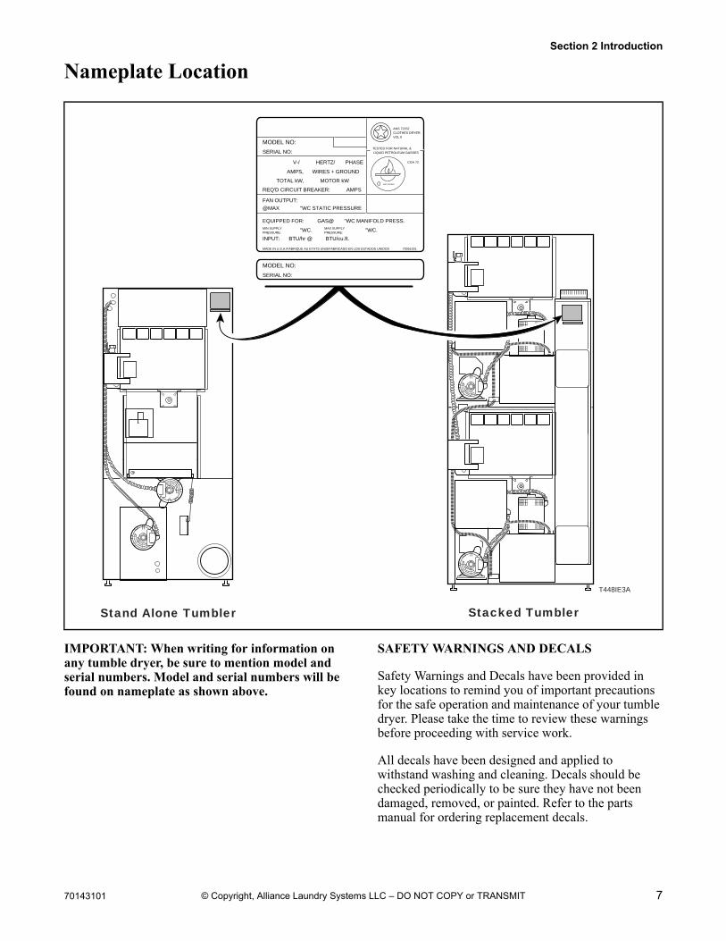
Nameplate Location
IMPORTANT: When writing for information on any tumble dryer, be sure to mention model and serial numbers. Model and serial numbers will be found on nameplate as shown above.
SAFETY WARNINGS AND DECALS
Safety Warnings and Decals have been provided in key locations to remind you of important precautions for the safe operation and maintenance of your tumble dryer. Please take the time to review these warnings before proceeding with service work.
All decals have been designed and applied to withstand washing and cleaning. Decals should be checked periodically to be sure they have not been damaged, removed, or painted. Refer to the parts manual for ordering replacement decals.
MODEL NO:
SERIAL NO:
V-/ HERTZ/ PHASE
AMPS, WIRES + GROUND
TOTAL kW, MOTOR kW
REQ'D CIRCUIT BREAKER: AMPS
FAN OUTPUT:
@MAX "WC STATIC PRESSURE
EQUIPPED FOR: GAS@ "WC MANIFOLD PRESS.MIN SUPPLYPRESSURE:
ANS 72152CLOTHES DRYER.VOL II
CGA 72
AMPLFIEDRER
TESTED FOR NATURAL & LIQUID PETROLEUM GASSES
MAX SUPPLYPRESSURE:"WC. "WC.
INPUT: BTU/hr @ BTU/cu.ft.
MADE IN U.S.A./FABRIQUE AU ETATS UNIS/FABRICADO EN LOS ESTADOS UNIDOS 70051001
T448IE3A
MODEL NO:
SERIAL NO:
Stand Alone Tumbler Stacked Tumbler
8 70143101
Section 2 Introduction
© Copyright, Alliance Laundry Systems LLC – DO NOT COPY or TRANSMIT
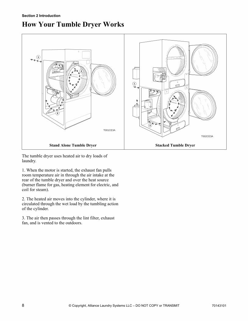
How Your Tumble Dryer Works
The tumble dryer uses heated air to dry loads of laundry.
1. When the motor is started, the exhaust fan pulls room temperature air in through the air intake at the rear of the tumble dryer and over the heat source (burner flame for gas, heating element for electric, and coil for steam).
2. The heated air moves into the cylinder, where it is circulated through the wet load by the tumbling action of the cylinder.
3. The air then passes through the lint filter, exhaust fan, and is vented to the outdoors.
Stand Alone Tumble Dryer Stacked Tumble Dryer
1
2
3
T001CE3A
1
2
3
T002CE3A
70143101 9
To reduce the risk of electric shock, fire, explosion, serious injury or death:• Disconnect electric power to the tumbler before servicing.• Close gas shut-off valve to gas tumbler before servicing.• Close steam valve to steam tumbler before servicing.• Never start the tumbler with any guards/panels removed.• Whenever ground wires are removed during servicing, these ground wires must be
reconnected to ensure that the tumbler is properly grounded.W002
WARNING
© Copyright, Alliance Laundry Systems LLC – DO NOT COPY or TRANSMIT
Section 3Troubleshooting
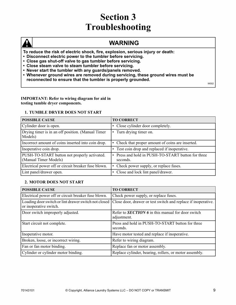
IMPORTANT: Refer to wiring diagram for aid in testing tumble dryer components.
1. TUMBLE DRYER DOES NOT START
2. MOTOR DOES NOT START
POSSIBLE CAUSE TO CORRECT
Cylinder door is open. • Close cylinder door completely.
Drying timer is in an off position. (Manual Timer Models)
• Turn drying timer on.
Incorrect amount of coins inserted into coin drop. • Check that proper amount of coins are inserted.
Inoperative coin drop. • Test coin drop and replaced if inoperative.
PUSH-TO-START button not properly activated. (Manual Timer Models)
• Press and hold in PUSH-TO-START button for three seconds.
Electrical power off or circuit breaker fuse blown. • Check power supply, or replace fuses.
Lint panel/drawer open. • Close and lock lint panel/drawer.
POSSIBLE CAUSE TO CORRECT
Electrical power off or circuit breaker fuse blown. Check power supply, or replace fuses.
Loading door switch or lint drawer switch not closed or inoperative switch.
Close door, drawer or test switch and replace if inoperative.
Door switch improperly adjusted. Refer to SECTION 6 in this manual for door switch adjustment.
Start circuit not complete. Press and hold in PUSH-TO-START button for three seconds.
Inoperative motor. Have motor tested and replace if inoperative.
Broken, loose, or incorrect wiring. Refer to wiring diagram.
Fan or fan motor binding. Replace fan or motor assembly.
Cylinder or cylinder motor binding. Replace cylinder, bearing, rollers, or motor assembly.
10 70143101
Section 3 Troubleshooting
To reduce the risk of electric shock, fire, explosion, serious injury or death:• Disconnect electric power to the tumbler before servicing.• Close gas shut-off valve to gas tumbler before servicing.• Close steam valve to steam tumbler before servicing.• Never start the tumbler with any guards/panels removed.• Whenever ground wires are removed during servicing, these ground wires must be
reconnected to ensure that the tumbler is properly grounded.W002
WARNING
© Copyright, Alliance Laundry Systems LLC – DO NOT COPY or TRANSMIT
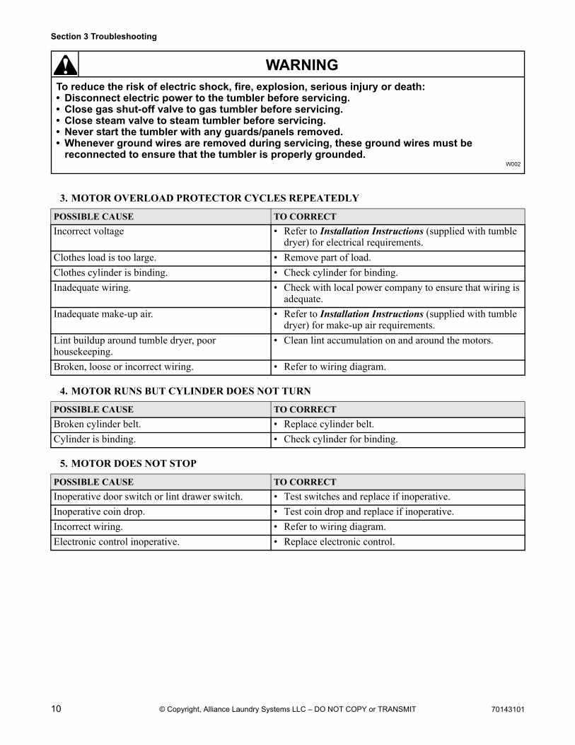
3. MOTOR OVERLOAD PROTECTOR CYCLES REPEATEDLY
4. MOTOR RUNS BUT CYLINDER DOES NOT TURN
5. MOTOR DOES NOT STOP
POSSIBLE CAUSE TO CORRECT
Incorrect voltage • Refer to Installation Instructions (supplied with tumble dryer) for electrical requirements.
Clothes load is too large. • Remove part of load.
Clothes cylinder is binding. • Check cylinder for binding.
Inadequate wiring. • Check with local power company to ensure that wiring is adequate.
Inadequate make-up air. • Refer to Installation Instructions (supplied with tumble dryer) for make-up air requirements.
Lint buildup around tumble dryer, poor housekeeping.
• Clean lint accumulation on and around the motors.
Broken, loose or incorrect wiring. • Refer to wiring diagram.
POSSIBLE CAUSE TO CORRECT
Broken cylinder belt. • Replace cylinder belt.
Cylinder is binding. • Check cylinder for binding.
POSSIBLE CAUSE TO CORRECT
Inoperative door switch or lint drawer switch. • Test switches and replace if inoperative.
Inoperative coin drop. • Test coin drop and replace if inoperative.
Incorrect wiring. • Refer to wiring diagram.
Electronic control inoperative. • Replace electronic control.
70143101 11
Section 3 Troubleshooting
To reduce the risk of electric shock, fire, explosion, serious injury or death:• Disconnect electric power to the tumbler before servicing.• Close gas shut-off valve to gas tumbler before servicing.• Close steam valve to steam tumbler before servicing.• Never start the tumbler with any guards/panels removed.• Whenever ground wires are removed during servicing, these ground wires must be
reconnected to ensure that the tumbler is properly grounded.W002
WARNING
© Copyright, Alliance Laundry Systems LLC – DO NOT COPY or TRANSMIT
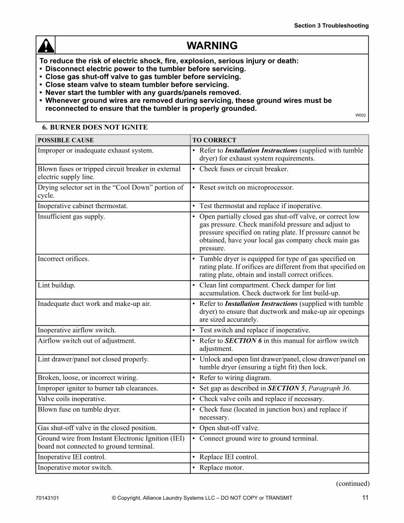
6. BURNER DOES NOT IGNITE
POSSIBLE CAUSE TO CORRECT
Improper or inadequate exhaust system. • Refer to Installation Instructions (supplied with tumble dryer) for exhaust system requirements.
Blown fuses or tripped circuit breaker in external electric supply line.
• Check fuses or circuit breaker.
Drying selector set in the “Cool Down” portion of cycle.
• Reset switch on microprocessor.
Inoperative cabinet thermostat. • Test thermostat and replace if inoperative.
Insufficient gas supply. • Open partially closed gas shut-off valve, or correct low gas pressure. Check manifold pressure and adjust to pressure specified on rating plate. If pressure cannot be obtained, have your local gas company check main gas pressure.
Incorrect orifices. • Tumble dryer is equipped for type of gas specified on rating plate. If orifices are different from that specified on rating plate, obtain and install correct orifices.
Lint buildup. • Clean lint compartment. Check damper for lint accumulation. Check ductwork for lint build-up.
Inadequate duct work and make-up air. • Refer to Installation Instructions (supplied with tumble dryer) to ensure that ductwork and make-up air openings are sized accurately.
Inoperative airflow switch. • Test switch and replace if inoperative.
Airflow switch out of adjustment. • Refer to SECTION 6 in this manual for airflow switch adjustment.
Lint drawer/panel not closed properly. • Unlock and open lint drawer/panel, close drawer/panel on tumble dryer (ensuring a tight fit) then lock.
Broken, loose, or incorrect wiring. • Refer to wiring diagram.
Improper igniter to burner tab clearances. • Set gap as described in SECTION 5, Paragraph 36.
Valve coils inoperative. • Check valve coils and replace if necessary.
Blown fuse on tumble dryer. • Check fuse (located in junction box) and replace if necessary.
Gas shut-off valve in the closed position. • Open shut-off valve.
Ground wire from Instant Electronic Ignition (IEI) board not connected to ground terminal.
• Connect ground wire to ground terminal.
Inoperative IEI control. • Replace IEI control.
Inoperative motor switch. • Replace motor.
(continued)
12 70143101
Section 3 Troubleshooting
To reduce the risk of electric shock, fire, explosion, serious injury or death:• Disconnect electric power to the tumbler before servicing.• Close gas shut-off valve to gas tumbler before servicing.• Close steam valve to steam tumbler before servicing.• Never start the tumbler with any guards/panels removed.• Whenever ground wires are removed during servicing, these ground wires must be
reconnected to ensure that the tumbler is properly grounded.W002
WARNING
© Copyright, Alliance Laundry Systems LLC – DO NOT COPY or TRANSMIT
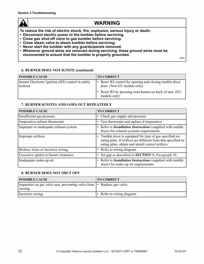
6. BURNER DOES NOT IGNITE (continued)
7. BURNER IGNITES AND GOES OUT REPEATEDLY
8. BURNER DOES NOT SHUT OFF
POSSIBLE CAUSE TO CORRECT
Instant Electronic Ignition (IEI) control in safety lockout.
• Reset IEI control by opening and closing tumble dryer door. (Non-EU models only)
• Reset IEI by pressing reset button on back of unit. (EU models only)
POSSIBLE CAUSE TO CORRECT
Insufficient gas pressure. • Check gas supply and pressure.
Inoperative cabinet thermostat. • Test thermostat and replace if inoperative.
Improper or inadequate exhaust system. • Refer to Installation Instructions (supplied with tumble dryer) for exhaust systems requirements.
Improper orifices. • Tumble dryer is equipped for type of gas specified on rating plate. If orifices are different from that specified on rating plate, obtain and install correct orifices.
Broken, loose or incorrect wiring. • Refer to wiring diagram.
Excessive igniter to burner clearance. • Set gap as described in SECTION 5, Paragraph 36.
Inadequate make-up air. • Refer to Installation Instructions (supplied with tumble dryer) for make-up air requirements.
POSSIBLE CAUSE TO CORRECT
Impurities on gas valve seat, preventing valve from closing.
• Replace gas valve.
Incorrect wiring. • Refer to wiring diagram.
70143101 13
Section 3 Troubleshooting
To reduce the risk of electric shock, fire, explosion, serious injury or death:• Disconnect electric power to the tumbler before servicing.• Close gas shut-off valve to gas tumbler before servicing.• Close steam valve to steam tumbler before servicing.• Never start the tumbler with any guards/panels removed.• Whenever ground wires are removed during servicing, these ground wires must be
reconnected to ensure that the tumbler is properly grounded.W002
WARNING
© Copyright, Alliance Laundry Systems LLC – DO NOT COPY or TRANSMIT
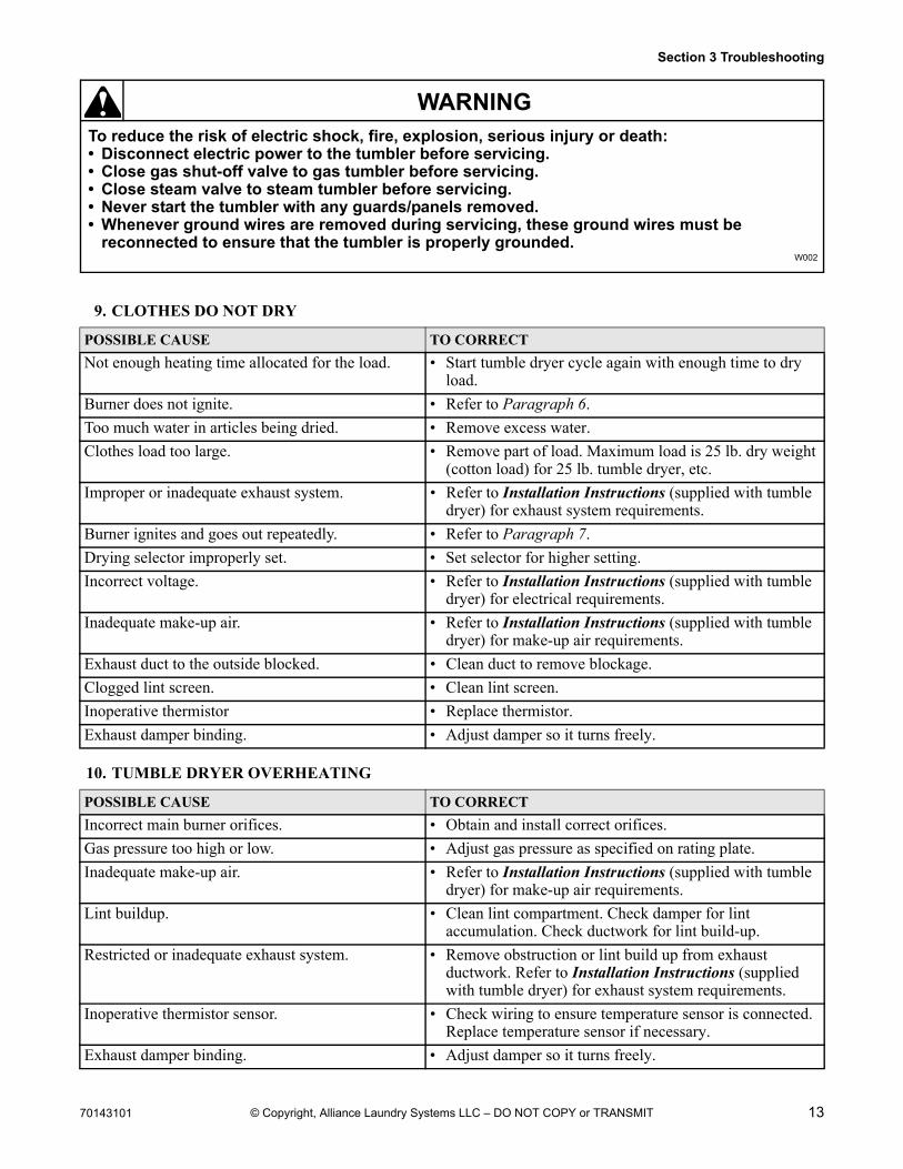
9. CLOTHES DO NOT DRY
10. TUMBLE DRYER OVERHEATING
POSSIBLE CAUSE TO CORRECT
Not enough heating time allocated for the load. • Start tumble dryer cycle again with enough time to dry load.
Burner does not ignite. • Refer to Paragraph 6.
Too much water in articles being dried. • Remove excess water.
Clothes load too large. • Remove part of load. Maximum load is 25 lb. dry weight (cotton load) for 25 lb. tumble dryer, etc.
Improper or inadequate exhaust system. • Refer to Installation Instructions (supplied with tumble dryer) for exhaust system requirements.
Burner ignites and goes out repeatedly. • Refer to Paragraph 7.
Drying selector improperly set. • Set selector for higher setting.
Incorrect voltage. • Refer to Installation Instructions (supplied with tumble dryer) for electrical requirements.
Inadequate make-up air. • Refer to Installation Instructions (supplied with tumble dryer) for make-up air requirements.
Exhaust duct to the outside blocked. • Clean duct to remove blockage.
Clogged lint screen. • Clean lint screen.
Inoperative thermistor • Replace thermistor.
Exhaust damper binding. • Adjust damper so it turns freely.
POSSIBLE CAUSE TO CORRECT
Incorrect main burner orifices. • Obtain and install correct orifices.
Gas pressure too high or low. • Adjust gas pressure as specified on rating plate.
Inadequate make-up air. • Refer to Installation Instructions (supplied with tumble dryer) for make-up air requirements.
Lint buildup. • Clean lint compartment. Check damper for lint accumulation. Check ductwork for lint build-up.
Restricted or inadequate exhaust system. • Remove obstruction or lint build up from exhaust ductwork. Refer to Installation Instructions (supplied with tumble dryer) for exhaust system requirements.
Inoperative thermistor sensor. • Check wiring to ensure temperature sensor is connected. Replace temperature sensor if necessary.
Exhaust damper binding. • Adjust damper so it turns freely.
14 70143101
Section 3 Troubleshooting
To reduce the risk of electric shock, fire, explosion, serious injury or death:• Disconnect electric power to the tumbler before servicing.• Close gas shut-off valve to gas tumbler before servicing.• Close steam valve to steam tumbler before servicing.• Never start the tumbler with any guards/panels removed.• Whenever ground wires are removed during servicing, these ground wires must be
reconnected to ensure that the tumbler is properly grounded.W002
WARNING
© Copyright, Alliance Laundry Systems LLC – DO NOT COPY or TRANSMIT
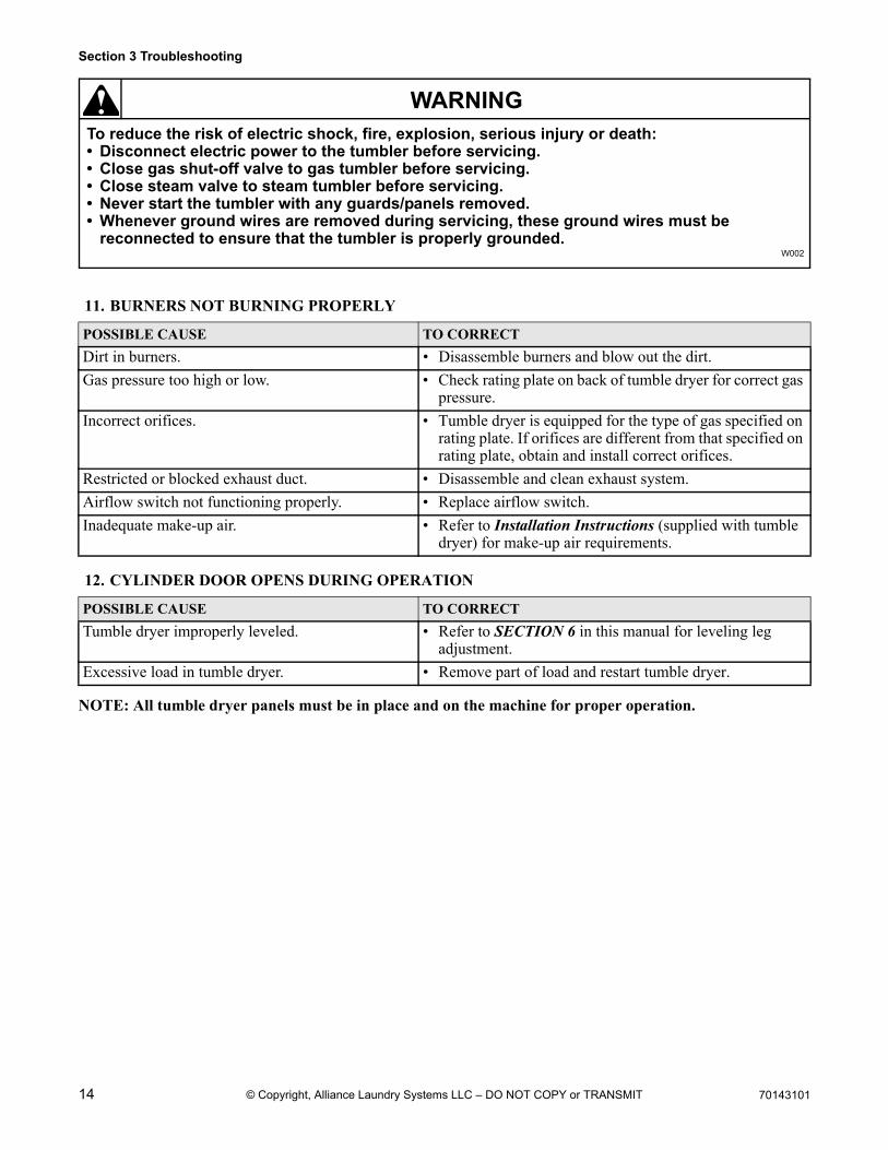
11. BURNERS NOT BURNING PROPERLY
12. CYLINDER DOOR OPENS DURING OPERATION
NOTE: All tumble dryer panels must be in place and on the machine for proper operation.
POSSIBLE CAUSE TO CORRECT
Dirt in burners. • Disassemble burners and blow out the dirt.
Gas pressure too high or low. • Check rating plate on back of tumble dryer for correct gas pressure.
Incorrect orifices. • Tumble dryer is equipped for the type of gas specified on rating plate. If orifices are different from that specified on rating plate, obtain and install correct orifices.
Restricted or blocked exhaust duct. • Disassemble and clean exhaust system.
Airflow switch not functioning properly. • Replace airflow switch.
Inadequate make-up air. • Refer to Installation Instructions (supplied with tumble dryer) for make-up air requirements.
POSSIBLE CAUSE TO CORRECT
Tumble dryer improperly leveled. • Refer to SECTION 6 in this manual for leveling leg adjustment.
Excessive load in tumble dryer. • Remove part of load and restart tumble dryer.
70143101 15
To reduce the risk of electric shock, fire, explosion, serious injury or death:• Disconnect electric power to the tumbler before servicing.• Close gas shut-off valve to gas tumbler before servicing.• Close steam valve to steam tumbler before servicing.• Never start the tumbler with any guards/panels removed.• Whenever ground wires are removed during servicing, these ground wires must be
reconnected to ensure that the tumbler is properly grounded.W002
WARNING
© Copyright, Alliance Laundry Systems LLC – DO NOT COPY or TRANSMIT
Section 4Grounding
Grounding Instructions
This tumble dryer must be grounded. In the event of malfunction or breakdown, grounding will reduce the risk of electric shock by providing the path of least resistance for electric current. This tumble dryer must be connected to a grounded metal, permanent wiring system; or an equipment grounding conductor must be run with the circuit conductors and connected to the appropriate ground location.
NOTE: To ensure protection against shock, this tumble dryer MUST be electrically grounded in accordance with local codes, or in the absence of local codes, with the latest edition of the National Electrical Code ANSI/NFPA No. 70. In Canada the electrical connections are to be made in accordance with CSA C22.1 or the latest edition of the Canadian Electrical Code, Part I and/or local codes. Electrical work should be done by a qualified electrician.
To reduce the risk of fire and electric shock, check with a qualified serviceperson for proper grounding procedures. Improper connection of the equipment grounding conductor may result in a risk of electric shock.
W068R1
WARNING
To reduce the risk of fire and electric shock, if electrical supply is coming from a three phase service, DO NOT connect a “High Leg” or “Stinger Leg” to a single phase machine. On a three phase machine, if there is a “High Leg” or “Stinger Leg” it should be connected to L3.
W069
WARNING
All electrical connections should be made by a qualified electrician.
To reduce the risk of electrical shock, de-energize the electrical circuit being connected to the tumbler before making any electrical connections. Never attempt to connect a live circuit.
W070
WARNING
16 70143101
Section 4 Grounding
© Copyright, Alliance Laundry Systems LLC – DO NOT COPY or TRANSMIT
Notes
70143101 17
To reduce the risk of electric shock, fire, explosion, serious injury or death:• Disconnect electric power to the tumbler before servicing.• Close gas shut-off valve to gas tumbler before servicing.• Close steam valve to steam tumbler before servicing.• Never start the tumbler with any guards/panels removed.• Whenever ground wires are removed during servicing, these ground wires must be
reconnected to ensure that the tumbler is properly grounded.W002
WARNING
© Copyright, Alliance Laundry Systems LLC – DO NOT COPY or TRANSMIT
Section 5Service Procedures
IMPORTANT: When reference is made to the left or right hand direction in this manual, it is from the service person’s position facing the front of the tumble dryer.
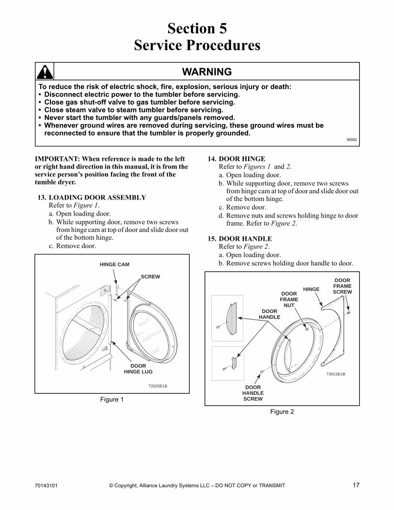
13. LOADING DOOR ASSEMBLYRefer to Figure 1.a. Open loading door.b. While supporting door, remove two screws
from hinge cam at top of door and slide door out of the bottom hinge.
c. Remove door.
14. DOOR HINGERefer to Figures 1 and 2.a. Open loading door.b. While supporting door, remove two screws
from hinge cam at top of door and slide door out of the bottom hinge.
c. Remove door.d. Remove nuts and screws holding hinge to door
frame. Refer to Figure 2.
15. DOOR HANDLERefer to Figure 2.a. Open loading door.b. Remove screws holding door handle to door.
Figure 1
T252SE1B
DOOR HINGE LUG
HINGE CAM
SCREW
Figure 2
T301SE1B
DOORHANDLE
DOORHANDLESCREW
DOORFRAME
NUT
HINGE
DOORFRAMESCREW
18 70143101
Section 5 Service Procedures
To reduce the risk of electric shock, fire, explosion, serious injury or death:• Disconnect electric power to the tumbler before servicing.• Close gas shut-off valve to gas tumbler before servicing.• Close steam valve to steam tumbler before servicing.• Never start the tumbler with any guards/panels removed.• Whenever ground wires are removed during servicing, these ground wires must be
reconnected to ensure that the tumbler is properly grounded.W002
WARNING
© Copyright, Alliance Laundry Systems LLC – DO NOT COPY or TRANSMIT
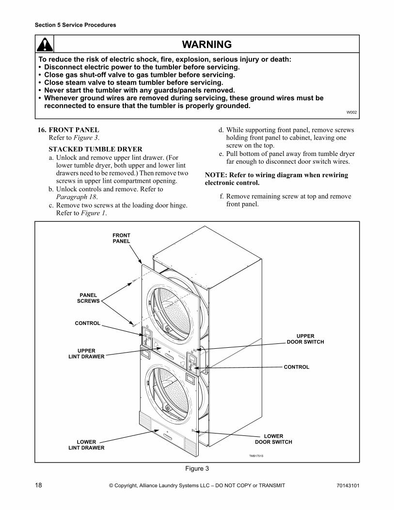
16. FRONT PANELRefer to Figure 3.
STACKED TUMBLE DRYERa. Unlock and remove upper lint drawer. (For
lower tumble dryer, both upper and lower lint drawers need to be removed.) Then remove two screws in upper lint compartment opening.
b. Unlock controls and remove. Refer to Paragraph 18.
c. Remove two screws at the loading door hinge. Refer to Figure 1.
d. While supporting front panel, remove screws holding front panel to cabinet, leaving one screw on the top.
e. Pull bottom of panel away from tumble dryer far enough to disconnect door switch wires.
NOTE: Refer to wiring diagram when rewiring electronic control.
f. Remove remaining screw at top and remove front panel.
Figure 3
START
25C
HIGHTEMP
MEDTEMPLOWTEMP
NOHEAT
1
2
3
SELECTTEMP
INSERTCOIN
PUSHSTART
1
2
3
SELECTTEMP
INSERTCOIN
PUSHSTART
START
25C
HIGHTEMP
MEDTEMPLOWTEMP
NOHEAT
TMB1751S
FRONTPANEL
PANELSCREWS
CONTROL
UPPERLINT DRAWER
LOWERLINT DRAWER
LOWERDOOR SWITCH
CONTROL
UPPERDOOR SWITCH
70143101 19
Section 5 Service Procedures
To reduce the risk of electric shock, fire, explosion, serious injury or death:• Disconnect electric power to the tumbler before servicing.• Close gas shut-off valve to gas tumbler before servicing.• Close steam valve to steam tumbler before servicing.• Never start the tumbler with any guards/panels removed.• Whenever ground wires are removed during servicing, these ground wires must be
reconnected to ensure that the tumbler is properly grounded.W002
WARNING
© Copyright, Alliance Laundry Systems LLC – DO NOT COPY or TRANSMIT
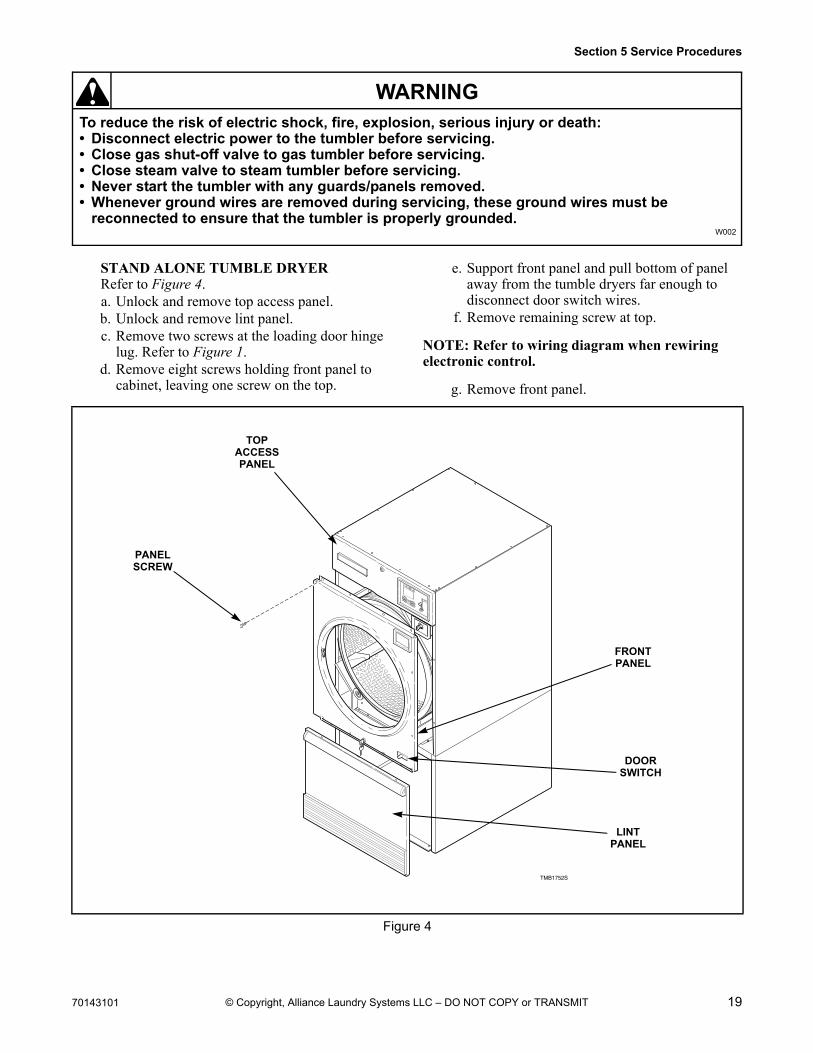
STAND ALONE TUMBLE DRYERRefer to Figure 4.a. Unlock and remove top access panel.b. Unlock and remove lint panel.c. Remove two screws at the loading door hinge
lug. Refer to Figure 1.d. Remove eight screws holding front panel to
cabinet, leaving one screw on the top.
e. Support front panel and pull bottom of panel away from the tumble dryers far enough to disconnect door switch wires.
f. Remove remaining screw at top.
NOTE: Refer to wiring diagram when rewiring electronic control.
g. Remove front panel.
Figure 4
START25C
HIGHTEMP
MEDTEMPLOWTEMP
NOHEAT
1
2
3
SELECTTEMP
INSERTCOIN
PUSHSTART
TMB1752S
FRONTPANEL
PANELSCREW
DOORSWITCH
TOPACCESSPANEL
LINTPANEL
20 70143101
Section 5 Service Procedures
To reduce the risk of electric shock, fire, explosion, serious injury or death:• Disconnect electric power to the tumbler before servicing.• Close gas shut-off valve to gas tumbler before servicing.• Close steam valve to steam tumbler before servicing.• Never start the tumbler with any guards/panels removed.• Whenever ground wires are removed during servicing, these ground wires must be
reconnected to ensure that the tumbler is properly grounded.W002
WARNING
© Copyright, Alliance Laundry Systems LLC – DO NOT COPY or TRANSMIT
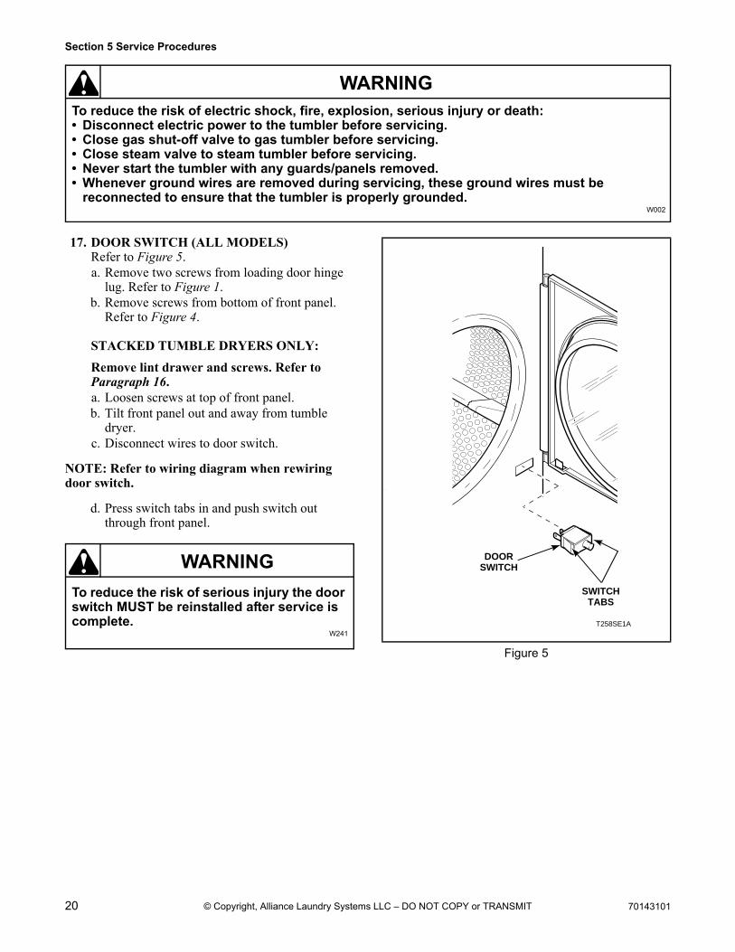
17. DOOR SWITCH (ALL MODELS)Refer to Figure 5.a. Remove two screws from loading door hinge
lug. Refer to Figure 1.b. Remove screws from bottom of front panel.
Refer to Figure 4.
STACKED TUMBLE DRYERS ONLY:
Remove lint drawer and screws. Refer to Paragraph 16.a. Loosen screws at top of front panel.b. Tilt front panel out and away from tumble
dryer.c. Disconnect wires to door switch.
NOTE: Refer to wiring diagram when rewiring door switch.
d. Press switch tabs in and push switch out through front panel.
To reduce the risk of serious injury the door switch MUST be reinstalled after service is complete.
W241
WARNING
Figure 5
T258SE1A
DOORSWITCH
SWITCHTABS
70143101 21
Section 5 Service Procedures
To reduce the risk of electric shock, fire, explosion, serious injury or death:• Disconnect electric power to the tumbler before servicing.• Close gas shut-off valve to gas tumbler before servicing.• Close steam valve to steam tumbler before servicing.• Never start the tumbler with any guards/panels removed.• Whenever ground wires are removed during servicing, these ground wires must be
reconnected to ensure that the tumbler is properly grounded.W002
WARNING
© Copyright, Alliance Laundry Systems LLC – DO NOT COPY or TRANSMIT
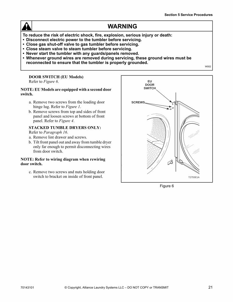
DOOR SWITCH (EU Models)Refer to Figure 6.
NOTE: EU Models are equipped with a second door switch.
a. Remove two screws from the loading door hinge lug. Refer to Figure 1.
b. Remove screws from top and sides of front panel and loosen screws at bottom of front panel. Refer to Figure 4.
STACKED TUMBLE DRYERS ONLY:Refer to Paragraph 16.a. Remove lint drawer and screws.b. Tilt front panel out and away from tumble dryer
only far enough to permit disconnecting wires from door switch.
NOTE: Refer to wiring diagram when rewiring door switch.
c. Remove two screws and nuts holding door switch to bracket on inside of front panel.
Figure 6
T275SE1A
EUDOOR
SWITCH
SCREWS

22 70143101
Section 5 Service Procedures
To reduce the risk of electric shock, fire, explosion, serious injury or death:• Disconnect electric power to the tumbler before servicing.• Close gas shut-off valve to gas tumbler before servicing.• Close steam valve to steam tumbler before servicing.• Never start the tumbler with any guards/panels removed.• Whenever ground wires are removed during servicing, these ground wires must be
reconnected to ensure that the tumbler is properly grounded.W002
WARNING
© Copyright, Alliance Laundry Systems LLC – DO NOT COPY or TRANSMIT
18. CONTROL AND COIN DROP ASSEMBLY
STACKED TUMBLE DRYERRefer to Figure 7.a. Unlock control/coin drop.b. Push down and in on bottom of control. Top of
control will tilt forward.c. Pull control out far enough to disconnect wires.d. Remove control and place in a clean, dry
location where it cannot be damaged.
IMPORTANT: Refer to wiring diagram when rewiring control.
STAND ALONE TUMBLE DRYERRefer to Figure 8.a. Unlock top access panel over control and
remove. Refer to Figure 4.b. Remove two screws from control door.c. Swing out control.d. Push up on control until top hinge clears slot.e. Disconnect wire harness from cabinet harness.f. Remove audit switch by pressing in on locking
tabs, pull out through front.g. Remove control and place in a clean dry
location where it cannot be damaged.
IMPORTANT: Refer to wiring diagram when rewiring control.
Figure 7
START
25C
HIGHTEMP
MEDTEMPLOWTEMP
NOHEAT
1
2
3
SELECTTEMP
INSERTCOIN
PUSHSTART
1
2
3
SELECTTEMP
INSERTCOIN
PUSHSTART
START
25C
HIGHTEMP
MEDTEMPLOWTEMP
NOHEAT
T313SE1A
CONTROL
CONTROLLOCK
COINVAULT(ObtainLocally)
Figure 8
START
25C
HIGHTEMP
MEDTEMPLOWTEMP
NOHEAT
1
2
3
SELECTTEMP
INSERTCOIN
PUSHSTART
TMB1753S
CONTROLDOOR
SCREWS
COINVAULT(Obtain Locally)
AUDITSWITCH
LINTPANELLOCK
LINTPANEL
70143101 23
Section 5 Service Procedures
To reduce the risk of electric shock, fire, explosion, serious injury or death:• Disconnect electric power to the tumbler before servicing.• Close gas shut-off valve to gas tumbler before servicing.• Close steam valve to steam tumbler before servicing.• Never start the tumbler with any guards/panels removed.• Whenever ground wires are removed during servicing, these ground wires must be
reconnected to ensure that the tumbler is properly grounded.W002
WARNING
© Copyright, Alliance Laundry Systems LLC – DO NOT COPY or TRANSMIT
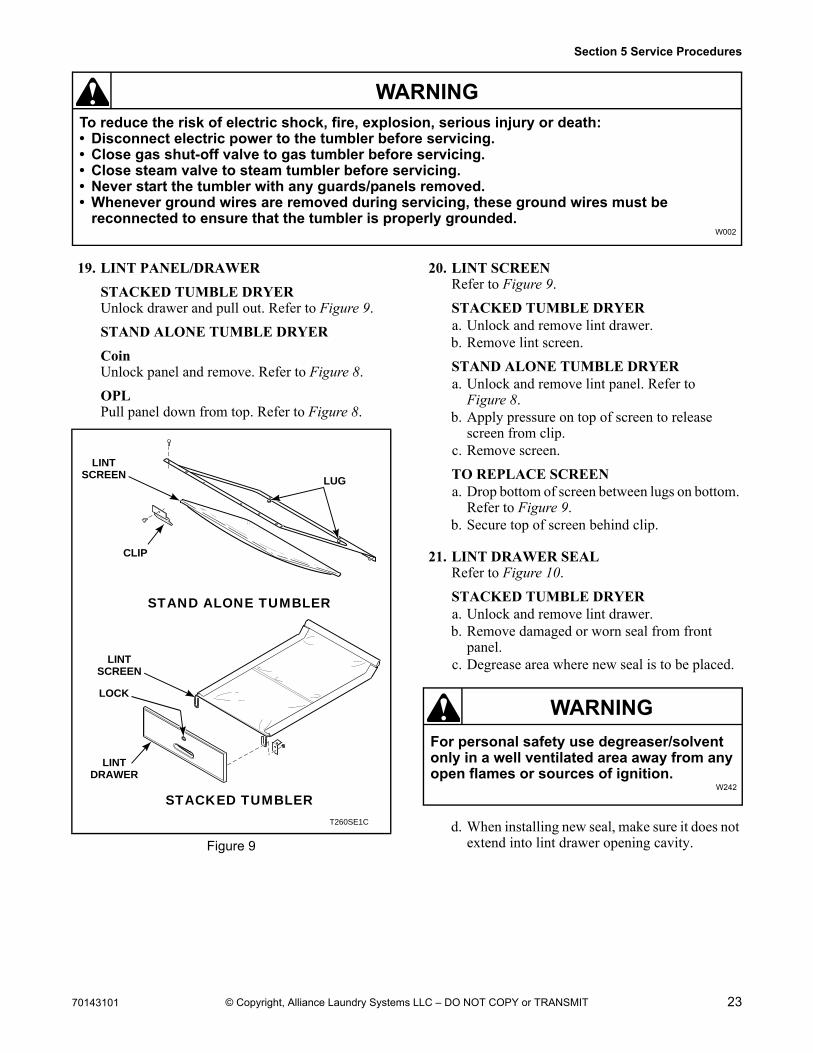
19. LINT PANEL/DRAWER
STACKED TUMBLE DRYERUnlock drawer and pull out. Refer to Figure 9.
STAND ALONE TUMBLE DRYER
CoinUnlock panel and remove. Refer to Figure 8.
OPLPull panel down from top. Refer to Figure 8.
20. LINT SCREENRefer to Figure 9.
STACKED TUMBLE DRYERa. Unlock and remove lint drawer.b. Remove lint screen.
STAND ALONE TUMBLE DRYERa. Unlock and remove lint panel. Refer to
Figure 8.b. Apply pressure on top of screen to release
screen from clip.c. Remove screen.
TO REPLACE SCREENa. Drop bottom of screen between lugs on bottom.
Refer to Figure 9.b. Secure top of screen behind clip.
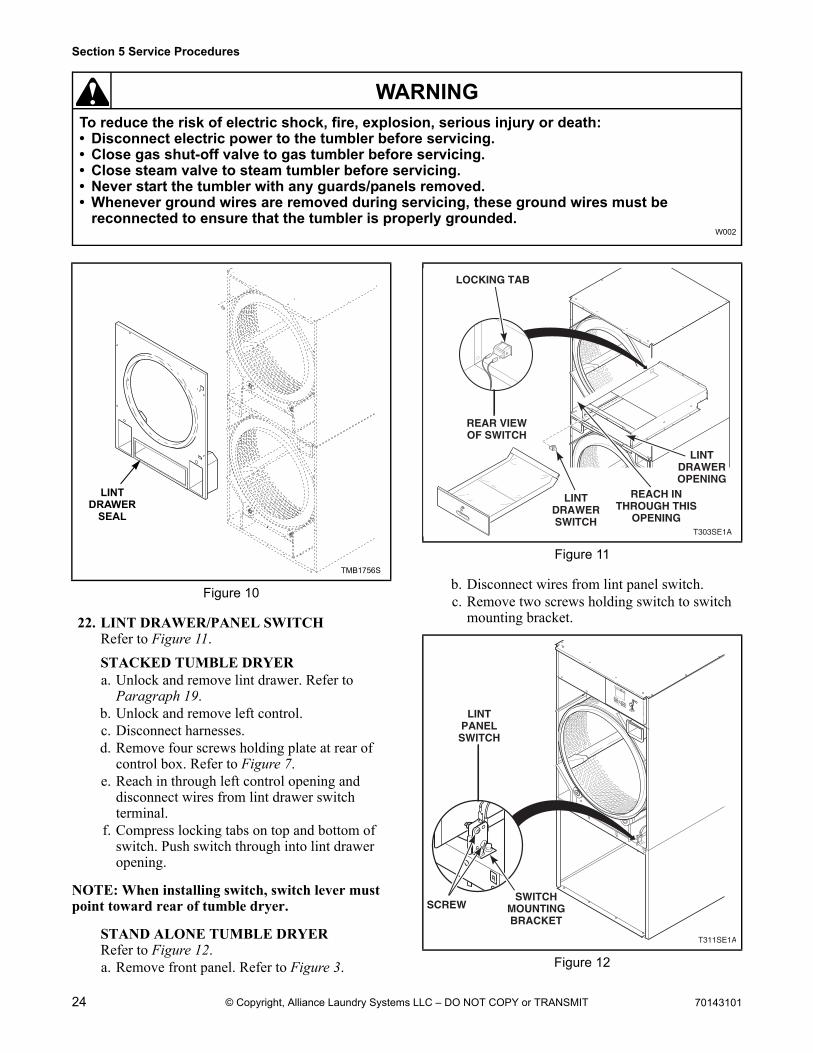
21. LINT DRAWER SEALRefer to Figure 10.
STACKED TUMBLE DRYERa. Unlock and remove lint drawer.b. Remove damaged or worn seal from front
panel.c. Degrease area where new seal is to be placed.
d. When installing new seal, make sure it does not extend into lint drawer opening cavity.Figure 9
T260SE1C
STAND ALONE TUMBLER
STACKED TUMBLER
LINTSCREEN
LINTSCREEN
LINTDRAWER
LOCK
CLIP
LUG
For personal safety use degreaser/solvent only in a well ventilated area away from any open flames or sources of ignition.
W242
WARNING
24 70143101
Section 5 Service Procedures
To reduce the risk of electric shock, fire, explosion, serious injury or death:• Disconnect electric power to the tumbler before servicing.• Close gas shut-off valve to gas tumbler before servicing.• Close steam valve to steam tumbler before servicing.• Never start the tumbler with any guards/panels removed.• Whenever ground wires are removed during servicing, these ground wires must be
reconnected to ensure that the tumbler is properly grounded.W002
WARNING
© Copyright, Alliance Laundry Systems LLC – DO NOT COPY or TRANSMIT
22. LINT DRAWER/PANEL SWITCHRefer to Figure 11.
STACKED TUMBLE DRYERa. Unlock and remove lint drawer. Refer to
Paragraph 19.b. Unlock and remove left control.c. Disconnect harnesses.d. Remove four screws holding plate at rear of
control box. Refer to Figure 7.e. Reach in through left control opening and
disconnect wires from lint drawer switch terminal.
f. Compress locking tabs on top and bottom of switch. Push switch through into lint drawer opening.
NOTE: When installing switch, switch lever must point toward rear of tumble dryer.
STAND ALONE TUMBLE DRYERRefer to Figure 12.a. Remove front panel. Refer to Figure 3.
b. Disconnect wires from lint panel switch.c. Remove two screws holding switch to switch
mounting bracket.
Figure 10
LINTDRAWER
SEAL
TMB1756S
Figure 11
Figure 12
T303SE1A
LINTDRAWERSWITCH
LINTDRAWEROPENING
LOCKING TAB
REACH INTHROUGH THIS
OPENING
REAR VIEWOF SWITCH
25CSTART
HIGHTEMP
MEDTEMPLOWTEMP
NOHEAT
1
2
3
SELECTTEMP
INSERTCOIN
PUSHSTART
T311SE1A
LINTPANELSWITCH
SWITCHMOUNTINGBRACKET
SCREW
70143101 25
Section 5 Service Procedures
To reduce the risk of electric shock, fire, explosion, serious injury or death:• Disconnect electric power to the tumbler before servicing.• Close gas shut-off valve to gas tumbler before servicing.• Close steam valve to steam tumbler before servicing.• Never start the tumbler with any guards/panels removed.• Whenever ground wires are removed during servicing, these ground wires must be
reconnected to ensure that the tumbler is properly grounded.W002
WARNING
© Copyright, Alliance Laundry Systems LLC – DO NOT COPY or TRANSMIT
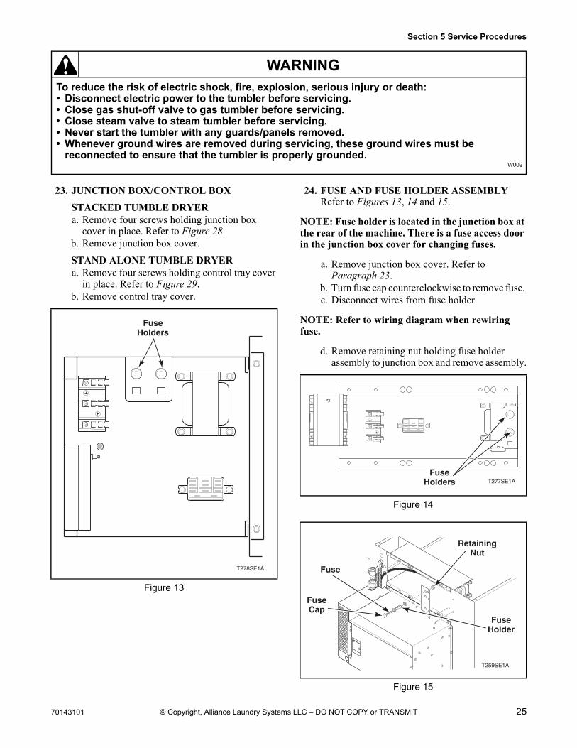
23. JUNCTION BOX/CONTROL BOX
STACKED TUMBLE DRYERa. Remove four screws holding junction box
cover in place. Refer to Figure 28.b. Remove junction box cover.
STAND ALONE TUMBLE DRYERa. Remove four screws holding control tray cover
in place. Refer to Figure 29.b. Remove control tray cover.
24. FUSE AND FUSE HOLDER ASSEMBLYRefer to Figures 13, 14 and 15.
NOTE: Fuse holder is located in the junction box at the rear of the machine. There is a fuse access door in the junction box cover for changing fuses.
a. Remove junction box cover. Refer to Paragraph 23.
b. Turn fuse cap counterclockwise to remove fuse. c. Disconnect wires from fuse holder.
NOTE: Refer to wiring diagram when rewiring fuse.
d. Remove retaining nut holding fuse holder assembly to junction box and remove assembly.
Figure 13
T278SE1A
FuseHolders
Figure 14
Figure 15
T277SE1AFuse
Holders
T259SE1A
FuseCap
FuseHolder
RetainingNut
Fuse
26 70143101
Section 5 Service Procedures
To reduce the risk of electric shock, fire, explosion, serious injury or death:• Disconnect electric power to the tumbler before servicing.• Close gas shut-off valve to gas tumbler before servicing.• Close steam valve to steam tumbler before servicing.• Never start the tumbler with any guards/panels removed.• Whenever ground wires are removed during servicing, these ground wires must be
reconnected to ensure that the tumbler is properly grounded.W002
WARNING
© Copyright, Alliance Laundry Systems LLC – DO NOT COPY or TRANSMIT
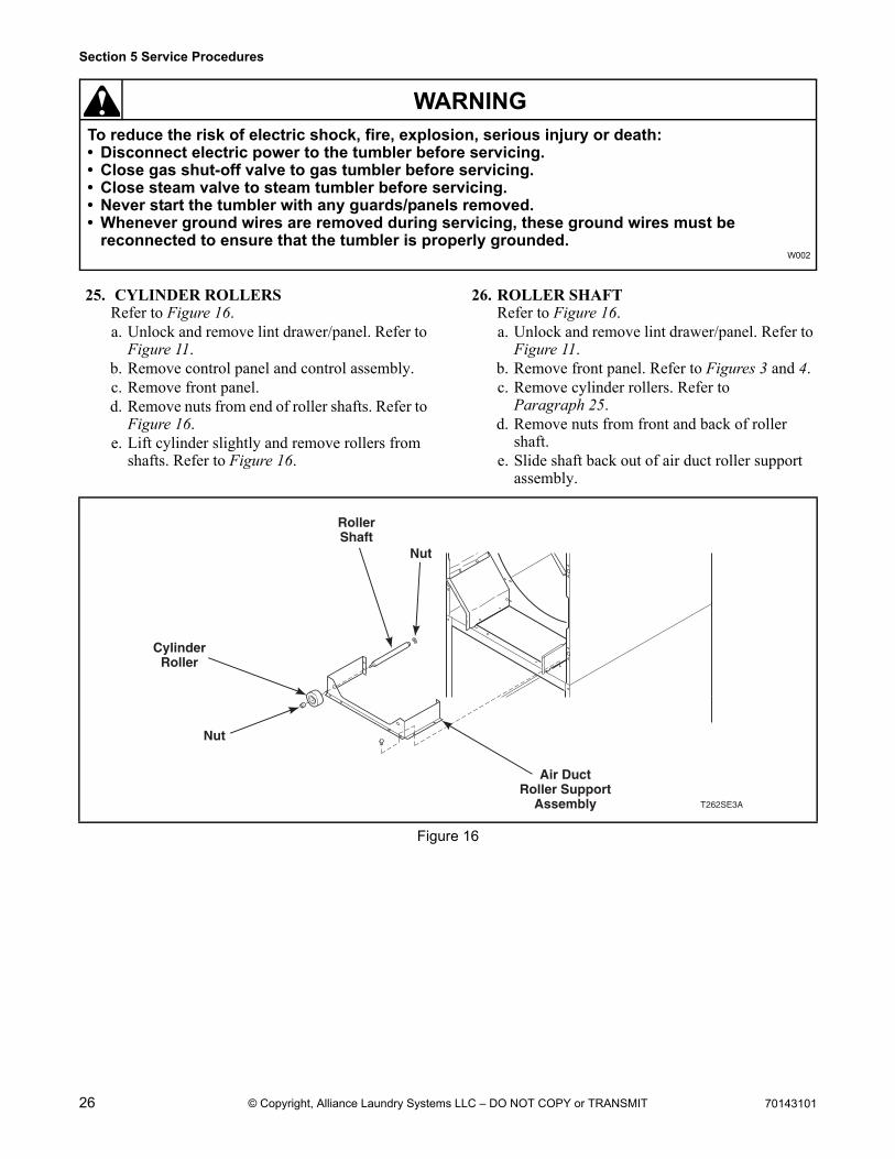
25. CYLINDER ROLLERSRefer to Figure 16.a. Unlock and remove lint drawer/panel. Refer to
Figure 11.b. Remove control panel and control assembly.c. Remove front panel.d. Remove nuts from end of roller shafts. Refer to
Figure 16.e. Lift cylinder slightly and remove rollers from
shafts. Refer to Figure 16.
26. ROLLER SHAFTRefer to Figure 16.a. Unlock and remove lint drawer/panel. Refer to
Figure 11.b. Remove front panel. Refer to Figures 3 and 4.c. Remove cylinder rollers. Refer to
Paragraph 25.d. Remove nuts from front and back of roller
shaft.e. Slide shaft back out of air duct roller support
assembly.
Figure 16
T262SE3A
CylinderRoller
RollerShaft
Nut
Nut
Air DuctRoller Support
Assembly
70143101 27
Section 5 Service Procedures
To reduce the risk of electric shock, fire, explosion, serious injury or death:• Disconnect electric power to the tumbler before servicing.• Close gas shut-off valve to gas tumbler before servicing.• Close steam valve to steam tumbler before servicing.• Never start the tumbler with any guards/panels removed.• Whenever ground wires are removed during servicing, these ground wires must be
reconnected to ensure that the tumbler is properly grounded.W002
WARNING
© Copyright, Alliance Laundry Systems LLC – DO NOT COPY or TRANSMIT
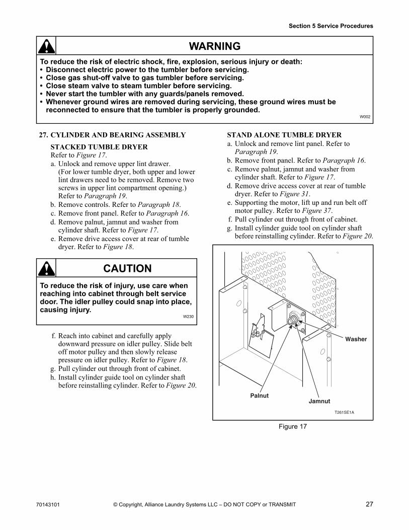
27. CYLINDER AND BEARING ASSEMBLY
STACKED TUMBLE DRYERRefer to Figure 17.a. Unlock and remove upper lint drawer.
(For lower tumble dryer, both upper and lower lint drawers need to be removed. Remove two screws in upper lint compartment opening.) Refer to Paragraph 19.
b. Remove controls. Refer to Paragraph 18.c. Remove front panel. Refer to Paragraph 16.d. Remove palnut, jamnut and washer from
cylinder shaft. Refer to Figure 17.e. Remove drive access cover at rear of tumble
dryer. Refer to Figure 18.
f. Reach into cabinet and carefully apply downward pressure on idler pulley. Slide belt off motor pulley and then slowly release pressure on idler pulley. Refer to Figure 18.
g. Pull cylinder out through front of cabinet.h. Install cylinder guide tool on cylinder shaft
before reinstalling cylinder. Refer to Figure 20.
STAND ALONE TUMBLE DRYERa. Unlock and remove lint panel. Refer to
Paragraph 19.b. Remove front panel. Refer to Paragraph 16.c. Remove palnut, jamnut and washer from
cylinder shaft. Refer to Figure 17.d. Remove drive access cover at rear of tumble
dryer. Refer to Figure 31.e. Supporting the motor, lift up and run belt off
motor pulley. Refer to Figure 37.f. Pull cylinder out through front of cabinet.g. Install cylinder guide tool on cylinder shaft
before reinstalling cylinder. Refer to Figure 20.
To reduce the risk of injury, use care when reaching into cabinet through belt service door. The idler pulley could snap into place, causing injury.
W230
CAUTION
Figure 17
T261SE1A
PalnutJamnut
Washer
28 70143101
Section 5 Service Procedures
To reduce the risk of electric shock, fire, explosion, serious injury or death:• Disconnect electric power to the tumbler before servicing.• Close gas shut-off valve to gas tumbler before servicing.• Close steam valve to steam tumbler before servicing.• Never start the tumbler with any guards/panels removed.• Whenever ground wires are removed during servicing, these ground wires must be
reconnected to ensure that the tumbler is properly grounded.W002
WARNING
© Copyright, Alliance Laundry Systems LLC – DO NOT COPY or TRANSMIT
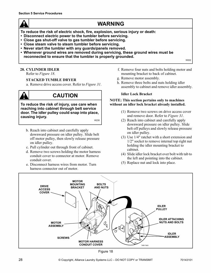
28. CYLINDER IDLER Refer to Figure 18.
STACKED TUMBLE DRYERa. Remove drive access cover. Refer to Figure 31.
b. Reach into cabinet and carefully apply downward pressure on idler pulley. Slide belt off motor pulley, then slowly release pressure on idler pulley.
c. Pull cylinder out through front of cabinet.d. Remove two screws holding the motor harness
conduit cover to connector at motor. Remove conduit cover.
e. Disconnect harness wires from motor. Turn harness connector out of motor.
f. Remove four nuts and bolts holding motor and mounting bracket to back of cabinet.
g. Remove motor assembly.h. Remove three bolts and nuts holding idler
assembly to cabinet and remove idler assembly.
Idler Lock Bracket
NOTE: This section pertains only to machines without an idler lock bracket already installed.
(1) Remove two screws on drive access cover and remove door. Refer to Figure 31.
(2) Reach into cabinet and carefully apply downward pressure on idler pulley. Slide belt off pulleys and slowly release pressure on idler pulley.
(3) Use 1/4" ratchet with a short extension and 1/2" socket to remove internal top right nut holding the idler mounting bracket to cabinet.
(4) Slide idler lock bracket over bolt with tab to the left and pointing into the cabinet.
(5) Replace nut and lock into place.
To reduce the risk of injury, use care when reaching into cabinet through belt service door. The idler pulley could snap into place, causing injury.
W230
CAUTION
Figure 18
TMB1766S
MOTORASSEMBLY
MOTORMOUNTINGBRACKET
BOLTSAND NUTS
IDLERPULLEY
IDLER ATTACHINGNUTS AND BOLTS
IDLERASSEMBLY
MOTOR HARNESSCONDUIT COVER
SCREWS
DRIVEACCESSCOVER
70143101 29
Section 5 Service Procedures
To reduce the risk of electric shock, fire, explosion, serious injury or death:• Disconnect electric power to the tumbler before servicing.• Close gas shut-off valve to gas tumbler before servicing.• Close steam valve to steam tumbler before servicing.• Never start the tumbler with any guards/panels removed.• Whenever ground wires are removed during servicing, these ground wires must be
reconnected to ensure that the tumbler is properly grounded.W002
WARNING
© Copyright, Alliance Laundry Systems LLC – DO NOT COPY or TRANSMIT
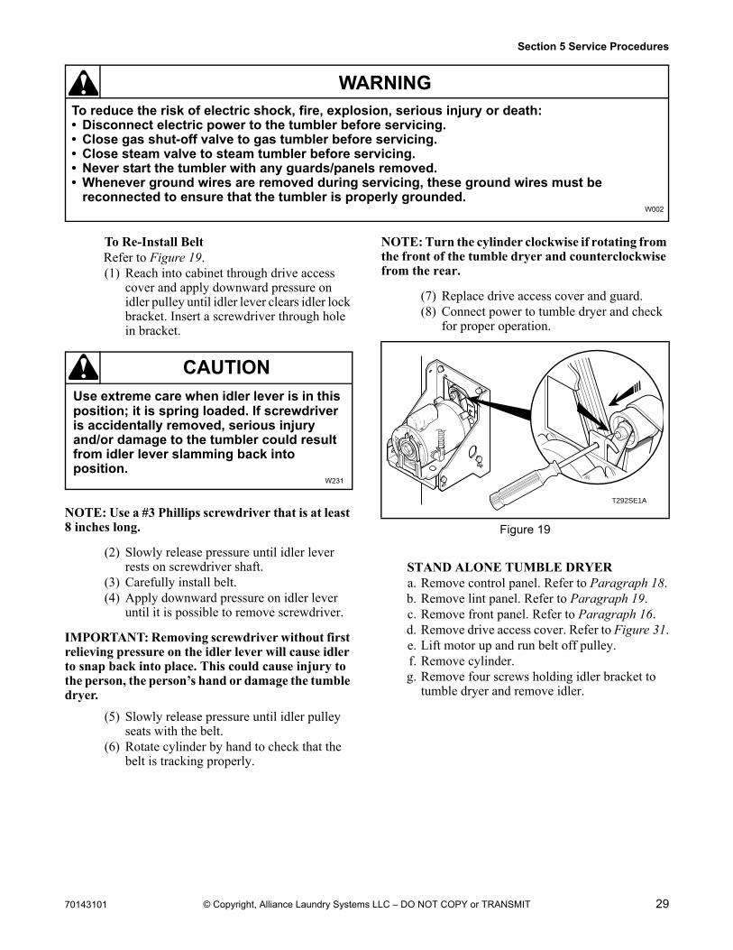
To Re-Install BeltRefer to Figure 19.(1) Reach into cabinet through drive access
cover and apply downward pressure on idler pulley until idler lever clears idler lock bracket. Insert a screwdriver through hole in bracket.
NOTE: Use a #3 Phillips screwdriver that is at least 8 inches long.
(2) Slowly release pressure until idler lever rests on screwdriver shaft.
(3) Carefully install belt.(4) Apply downward pressure on idler lever
until it is possible to remove screwdriver.
IMPORTANT: Removing screwdriver without first relieving pressure on the idler lever will cause idler to snap back into place. This could cause injury to the person, the person’s hand or damage the tumble dryer.
(5) Slowly release pressure until idler pulley seats with the belt.
(6) Rotate cylinder by hand to check that the belt is tracking properly.
NOTE: Turn the cylinder clockwise if rotating from the front of the tumble dryer and counterclockwise from the rear.
(7) Replace drive access cover and guard.(8) Connect power to tumble dryer and check
for proper operation.
STAND ALONE TUMBLE DRYERa. Remove control panel. Refer to Paragraph 18.b. Remove lint panel. Refer to Paragraph 19.c. Remove front panel. Refer to Paragraph 16.d. Remove drive access cover. Refer to Figure 31.e. Lift motor up and run belt off pulley.f. Remove cylinder.g. Remove four screws holding idler bracket to
tumble dryer and remove idler.
Use extreme care when idler lever is in this position; it is spring loaded. If screwdriver is accidentally removed, serious injury and/or damage to the tumbler could result from idler lever slamming back into position.
W231
CAUTION
Figure 19
T292SE1A
30 70143101
Section 5 Service Procedures
To reduce the risk of electric shock, fire, explosion, serious injury or death:• Disconnect electric power to the tumbler before servicing.• Close gas shut-off valve to gas tumbler before servicing.• Close steam valve to steam tumbler before servicing.• Never start the tumbler with any guards/panels removed.• Whenever ground wires are removed during servicing, these ground wires must be
reconnected to ensure that the tumbler is properly grounded.W002
WARNING
© Copyright, Alliance Laundry Systems LLC – DO NOT COPY or TRANSMIT
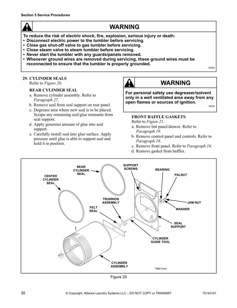
29. CYLINDER SEALSRefer to Figure 20.
REAR CYLINDER SEALa. Remove cylinder assembly. Refer to
Paragraph 27.b. Remove seal from seal support on rear panel.c. Degrease area where new seal is to be placed.
Scrape any remaining seal/glue remnants from seal support.
d. Apply generous amount of glue into seal support.
e. Carefully install seal into glue surface. Apply pressure until glue is able to support seal and hold it in position.
FRONT BAFFLE GASKETSRefer to Figure 21.a. Remove lint panel/drawer. Refer to
Paragraph 19.b. Remove control panel and controls. Refer to
Paragraph 18.c. Remove front panel. Refer to Paragraph 16.d. Remove gasket from baffles.
For personal safety use degreaser/solvent only in a well ventilated area away from any open flames or sources of ignition.
W242
WARNING
Figure 20
TMB1754STMB1754S
CENTER CYLINDER
SEAL
REARCYLINDER
SEAL
TRUNNIONASSEMBLY
FELTSEAL
CYLINDERASSEMBLY
BEARING
WASHER
PALNUT
JAM NUT
SUPPORTSCREWS
CYLINDERGUIDE TOOL
SEALSUPPORT
70143101 31
Section 5 Service Procedures
To reduce the risk of electric shock, fire, explosion, serious injury or death:• Disconnect electric power to the tumbler before servicing.• Close gas shut-off valve to gas tumbler before servicing.• Close steam valve to steam tumbler before servicing.• Never start the tumbler with any guards/panels removed.• Whenever ground wires are removed during servicing, these ground wires must be
reconnected to ensure that the tumbler is properly grounded.W002
WARNING
© Copyright, Alliance Laundry Systems LLC – DO NOT COPY or TRANSMIT
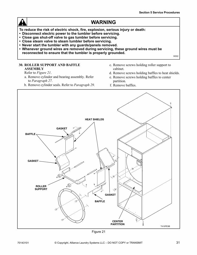
30. ROLLER SUPPORT AND BAFFLE ASSEMBLYRefer to Figure 21.a. Remove cylinder and bearing assembly. Refer
to Paragraph 27.b. Remove cylinder seals. Refer to Paragraph 29.
c. Remove screws holding roller support to cabinet.
d. Remove screws holding baffles to heat shields.e. Remove screws holding baffles to center
partition.f. Remove baffles.
Figure 21
T410PE3B
BAFFLE
GASKET
GASKET
GASKET
ROLLERSUPPORT
CENTERPARTITION
HEAT SHIELDS
BAFFLE
32 70143101
Section 5 Service Procedures
To reduce the risk of electric shock, fire, explosion, serious injury or death:• Disconnect electric power to the tumbler before servicing.• Close gas shut-off valve to gas tumbler before servicing.• Close steam valve to steam tumbler before servicing.• Never start the tumbler with any guards/panels removed.• Whenever ground wires are removed during servicing, these ground wires must be
reconnected to ensure that the tumbler is properly grounded.W002
WARNING
© Copyright, Alliance Laundry Systems LLC – DO NOT COPY or TRANSMIT
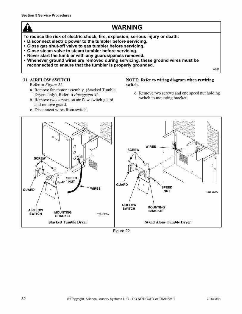
31. AIRFLOW SWITCHRefer to Figure 22.a. Remove fan motor assembly. (Stacked Tumble
Dryers only). Refer to Paragraph 46.b. Remove two screws on air flow switch guard
and remove guard.c. Disconnect wires from switch.
NOTE: Refer to wiring diagram when rewiring switch.
d. Remove two screws and one speed nut holding switch to mounting bracket.
Stacked Tumble Dryer Stand Alone Tumble Dryer
Figure 22
T264SE1A
GUARD
SCREW
WIRES
SPEEDNUT
AIRFLOWSWITCH MOUNTING
BRACKET
T265SE1A
GUARD
AIRFLOWSWITCH MOUNTING
BRACKET
SCREW
SPEEDNUT
WIRES
70143101 33
Section 5 Service Procedures
To reduce the risk of electric shock, fire, explosion, serious injury or death:• Disconnect electric power to the tumbler before servicing.• Close gas shut-off valve to gas tumbler before servicing.• Close steam valve to steam tumbler before servicing.• Never start the tumbler with any guards/panels removed.• Whenever ground wires are removed during servicing, these ground wires must be
reconnected to ensure that the tumbler is properly grounded.W002
WARNING
© Copyright, Alliance Laundry Systems LLC – DO NOT COPY or TRANSMIT
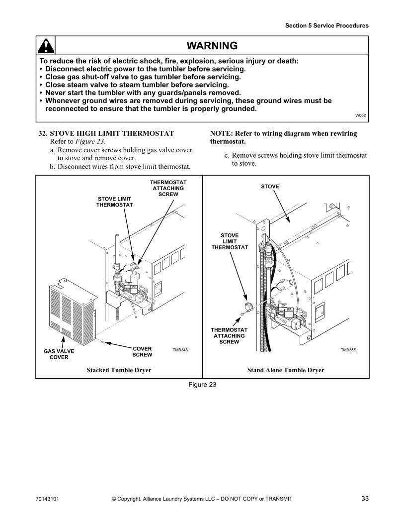
32. STOVE HIGH LIMIT THERMOSTATRefer to Figure 23.a. Remove cover screws holding gas valve cover
to stove and remove cover.b. Disconnect wires from stove limit thermostat.
NOTE: Refer to wiring diagram when rewiring thermostat.
c. Remove screws holding stove limit thermostat to stove.
Stacked Tumble Dryer Stand Alone Tumble Dryer
Figure 23
TMB34S
60%
TMB34S
STOVE LIMIT THERMOSTAT
COVERSCREW
GAS VALVECOVER
THERMOSTATATTACHING
SCREW
TMB35S
75%
TMB35S
STOVELIMIT
THERMOSTAT
THERMOSTATATTACHING
SCREW
STOVE
34 70143101
Section 5 Service Procedures
To reduce the risk of electric shock, fire, explosion, serious injury or death:• Disconnect electric power to the tumbler before servicing.• Close gas shut-off valve to gas tumbler before servicing.• Close steam valve to steam tumbler before servicing.• Never start the tumbler with any guards/panels removed.• Whenever ground wires are removed during servicing, these ground wires must be
reconnected to ensure that the tumbler is properly grounded.W002
WARNING
© Copyright, Alliance Laundry Systems LLC – DO NOT COPY or TRANSMIT
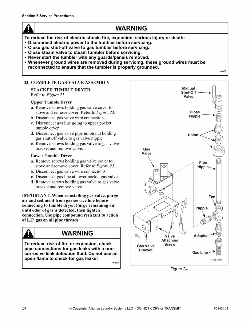
33. COMPLETE GAS VALVE ASSEMBLY
STACKED TUMBLE DRYERRefer to Figure 21.
Upper Tumble Dryera. Remove screws holding gas valve cover to
stove and remove cover. Refer to Figure 23.b. Disconnect gas valve wire connections.c. Disconnect gas line going to upper pocket
tumble dryer.d. Disconnect gas valve pipe union nut holding
gas shut off valve to gas valve nipple.e. Remove screws holding gas valve to gas valve
bracket and remove valve.
Lower Tumble Dryera. Remove screws holding gas valve cover to
stove and remove cover. Refer to Figure 23.b. Disconnect gas valve wire connections.c. Disconnect gas line at lower pocket gas valve.d. Remove screws holding gas valve to gas valve
bracket and remove valve.
IMPORTANT: When reinstalling gas valve, purge air and sediment from gas service line before connecting to tumble dryer. Purge remaining air until odor of gas is detected, then tighten connection. Use pipe compound resistant to action of L.P. gas on all pipe threads.
To reduce risk of fire or explosion, check pipe connections for gas leaks with a non-corrosive leak detection fluid. Do not use an open flame to check for gas leaks!
W310
WARNING
Figure 24
T298SE1B
GasValve
ManualShut-Off
Valve
CloseNipple
Union
PipeNipple
Tee
Nipple
Adapter
Gas Line
ValveAttaching
ScrewGas ValveBracket
70143101 35
Section 5 Service Procedures
To reduce the risk of electric shock, fire, explosion, serious injury or death:• Disconnect electric power to the tumbler before servicing.• Close gas shut-off valve to gas tumbler before servicing.• Close steam valve to steam tumbler before servicing.• Never start the tumbler with any guards/panels removed.• Whenever ground wires are removed during servicing, these ground wires must be
reconnected to ensure that the tumbler is properly grounded.W002
WARNING
© Copyright, Alliance Laundry Systems LLC – DO NOT COPY or TRANSMIT
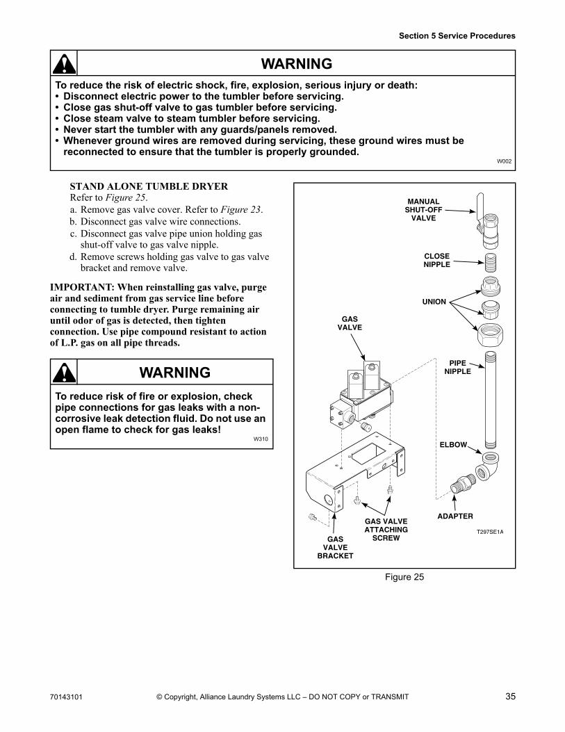
STAND ALONE TUMBLE DRYERRefer to Figure 25.a. Remove gas valve cover. Refer to Figure 23.b. Disconnect gas valve wire connections.c. Disconnect gas valve pipe union holding gas
shut-off valve to gas valve nipple.d. Remove screws holding gas valve to gas valve
bracket and remove valve.
IMPORTANT: When reinstalling gas valve, purge air and sediment from gas service line before connecting to tumble dryer. Purge remaining air until odor of gas is detected, then tighten connection. Use pipe compound resistant to action of L.P. gas on all pipe threads.
To reduce risk of fire or explosion, check pipe connections for gas leaks with a non-corrosive leak detection fluid. Do not use an open flame to check for gas leaks!
W310
WARNING
Figure 25
T297SE1A
GASVALVE
MANUALSHUT-OFF
VALVE
CLOSENIPPLE
UNION
PIPENIPPLE
ELBOW
ADAPTERGAS VALVEATTACHING
SCREWGASVALVE
BRACKET
36 70143101
Section 5 Service Procedures
To reduce the risk of electric shock, fire, explosion, serious injury or death:• Disconnect electric power to the tumbler before servicing.• Close gas shut-off valve to gas tumbler before servicing.• Close steam valve to steam tumbler before servicing.• Never start the tumbler with any guards/panels removed.• Whenever ground wires are removed during servicing, these ground wires must be
reconnected to ensure that the tumbler is properly grounded.W002
WARNING
© Copyright, Alliance Laundry Systems LLC – DO NOT COPY or TRANSMIT
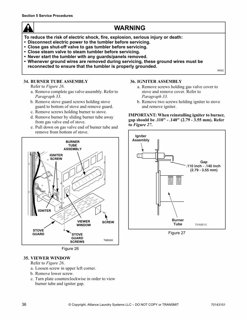
34. BURNER TUBE ASSEMBLYRefer to Figure 26.a. Remove complete gas valve assembly. Refer to
Paragraph 33.b. Remove stove guard screws holding stove
guard to bottom of stove and remove guard.c. Remove screws holding burner to stove.d. Remove burner by sliding burner tube away
from gas valve end of stove.e. Pull down on gas valve end of burner tube and
remove from bottom of stove.
35. VIEWER WINDOWRefer to Figure 26.a. Loosen screw in upper left corner.b. Remove lower screw.c. Turn plate counterclockwise in order to view
burner tube and igniter gap.
36. IGNITER ASSEMBLYa. Remove screws holding gas valve cover to
stove and remove cover. Refer to Paragraph 33.
b. Remove two screws holding igniter to stove and remove igniter.
IMPORTANT: When reinstalling igniter to burner, gap should be .110" - .140" (2.79 - 3.55 mm). Refer to Figure 27.
Figure 26
TMB36S
TMB36S
BURNERTUBE
ASSEMBLY
VIEWERWINDOW
STOVEGUARD STOVE
GUARDSCREWS
IGNITER
SCREW
IGNITERSCREW
Figure 27
T276SE1C
BurnerTube
IgniterAssembly
Gap.110 inch - .140 inch
(2.79 - 3.55 mm)
70143101 37
Section 5 Service Procedures
To reduce the risk of electric shock, fire, explosion, serious injury or death:• Disconnect electric power to the tumbler before servicing.• Close gas shut-off valve to gas tumbler before servicing.• Close steam valve to steam tumbler before servicing.• Never start the tumbler with any guards/panels removed.• Whenever ground wires are removed during servicing, these ground wires must be
reconnected to ensure that the tumbler is properly grounded.W002
WARNING
© Copyright, Alliance Laundry Systems LLC – DO NOT COPY or TRANSMIT
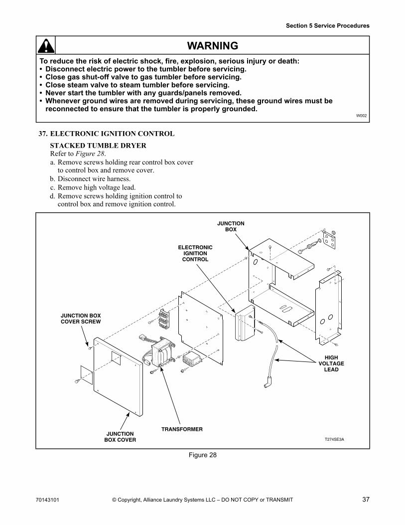
37. ELECTRONIC IGNITION CONTROL
STACKED TUMBLE DRYERRefer to Figure 28.a. Remove screws holding rear control box cover
to control box and remove cover.b. Disconnect wire harness.c. Remove high voltage lead.d. Remove screws holding ignition control to
control box and remove ignition control.
Figure 28
T274SE3A
TRANSFORMER
HIGHVOLTAGE
LEAD
ELECTRONICIGNITIONCONTROL
JUNCTIONBOX
JUNCTION BOXCOVER SCREW
JUNCTIONBOX COVER
38 70143101
Section 5 Service Procedures
To reduce the risk of electric shock, fire, explosion, serious injury or death:• Disconnect electric power to the tumbler before servicing.• Close gas shut-off valve to gas tumbler before servicing.• Close steam valve to steam tumbler before servicing.• Never start the tumbler with any guards/panels removed.• Whenever ground wires are removed during servicing, these ground wires must be
reconnected to ensure that the tumbler is properly grounded.W002
WARNING
© Copyright, Alliance Laundry Systems LLC – DO NOT COPY or TRANSMIT
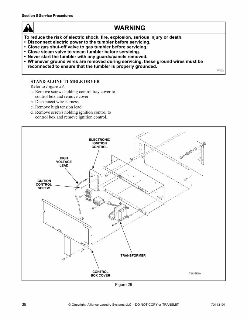
STAND ALONE TUMBLE DRYERRefer to Figure 29.a. Remove screws holding control tray cover to
control box and remove cover.b. Disconnect wire harness.c. Remove high tension lead.d. Remove screws holding ignition control to
control box and remove ignition control.
Figure 29
T273SE3A
TRANSFORMER
CONTROLBOX COVER
HIGHVOLTAGE
LEAD
ELECTRONICIGNITIONCONTROL
IGNITIONCONTROL
SCREW
70143101 39
Section 5 Service Procedures
To reduce the risk of electric shock, fire, explosion, serious injury or death:• Disconnect electric power to the tumbler before servicing.• Close gas shut-off valve to gas tumbler before servicing.• Close steam valve to steam tumbler before servicing.• Never start the tumbler with any guards/panels removed.• Whenever ground wires are removed during servicing, these ground wires must be
reconnected to ensure that the tumbler is properly grounded.W002
WARNING
© Copyright, Alliance Laundry Systems LLC – DO NOT COPY or TRANSMIT
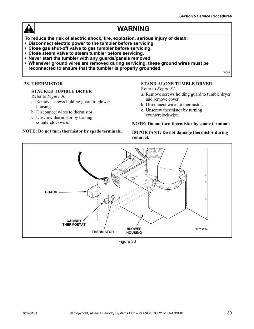
38. THERMISTOR
STACKED TUMBLE DRYERRefer to Figure 30.a. Remove screws holding guard to blower
housing.b. Disconnect wires to thermistor.c. Unscrew thermistor by turning
counterclockwise.
NOTE: Do not turn thermistor by spade terminals.
STAND ALONE TUMBLE DRYERRefer to Figure 31.a. Remove screws holding guard to tumble dryer
and remove cover.b. Disconnect wires to thermistor.c. Unscrew thermistor by turning
counterclockwise.
NOTE: Do not turn thermistor by spade terminals.
IMPORTANT: Do not damage thermistor during removal.
Figure 30
T270SE3ATHERMISTOR
BLOWERHOUSING
GUARD
CABINETTHERMOSTAT
40 70143101
Section 5 Service Procedures
To reduce the risk of electric shock, fire, explosion, serious injury or death:• Disconnect electric power to the tumbler before servicing.• Close gas shut-off valve to gas tumbler before servicing.• Close steam valve to steam tumbler before servicing.• Never start the tumbler with any guards/panels removed.• Whenever ground wires are removed during servicing, these ground wires must be
reconnected to ensure that the tumbler is properly grounded.W002
WARNING
© Copyright, Alliance Laundry Systems LLC – DO NOT COPY or TRANSMIT
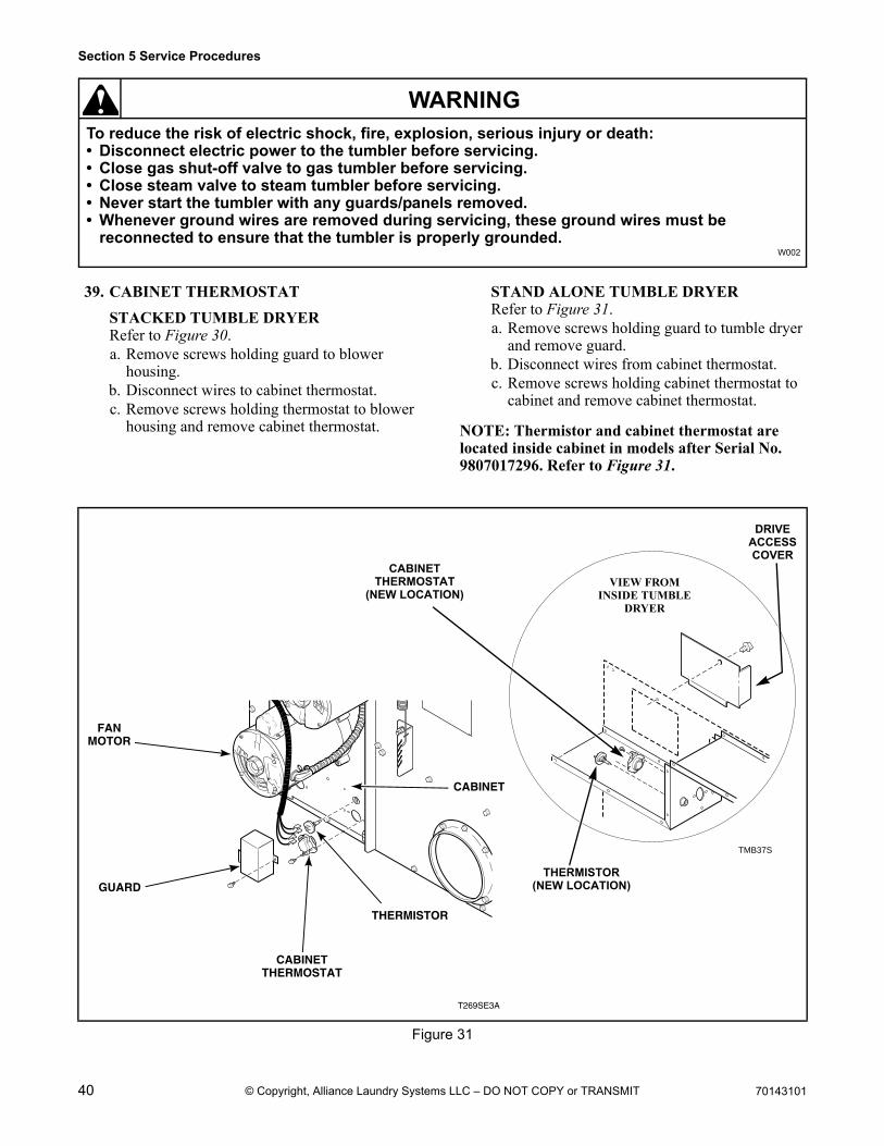
39. CABINET THERMOSTAT
STACKED TUMBLE DRYERRefer to Figure 30.a. Remove screws holding guard to blower
housing.b. Disconnect wires to cabinet thermostat.c. Remove screws holding thermostat to blower
housing and remove cabinet thermostat.
STAND ALONE TUMBLE DRYERRefer to Figure 31.a. Remove screws holding guard to tumble dryer
and remove guard.b. Disconnect wires from cabinet thermostat.c. Remove screws holding cabinet thermostat to
cabinet and remove cabinet thermostat.
NOTE: Thermistor and cabinet thermostat are located inside cabinet in models after Serial No. 9807017296. Refer to Figure 31.
Figure 31
TMB37S
T269SE3A
THERMISTOR
CABINETTHERMOSTAT
CABINET
GUARD
FANMOTOR
CABINETTHERMOSTAT
(NEW LOCATION)VIEW FROM
INSIDE TUMBLE DRYER
THERMISTOR(NEW LOCATION)
DRIVEACCESSCOVER
70143101 41
Section 5 Service Procedures
To reduce the risk of electric shock, fire, explosion, serious injury or death:• Disconnect electric power to the tumbler before servicing.• Close gas shut-off valve to gas tumbler before servicing.• Close steam valve to steam tumbler before servicing.• Never start the tumbler with any guards/panels removed.• Whenever ground wires are removed during servicing, these ground wires must be
reconnected to ensure that the tumbler is properly grounded.W002
WARNING
© Copyright, Alliance Laundry Systems LLC – DO NOT COPY or TRANSMIT
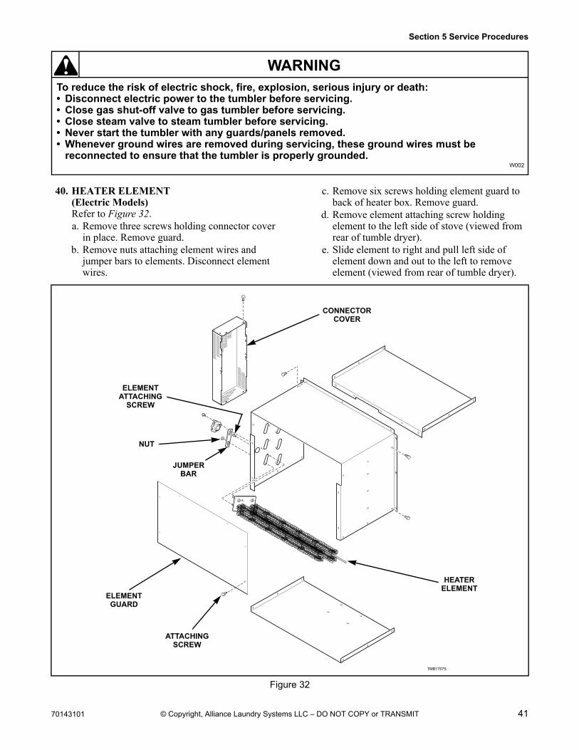
40. HEATER ELEMENT(Electric Models)Refer to Figure 32.a. Remove three screws holding connector cover
in place. Remove guard.b. Remove nuts attaching element wires and
jumper bars to elements. Disconnect element wires.
c. Remove six screws holding element guard to back of heater box. Remove guard.
d. Remove element attaching screw holding element to the left side of stove (viewed from rear of tumble dryer).
e. Slide element to right and pull left side of element down and out to the left to remove element (viewed from rear of tumble dryer).
Figure 32
TMB1757S
HEATERELEMENT
CONNECTORCOVER
ELEMENTGUARD
ATTACHINGSCREW
ELEMENTATTACHING
SCREW
NUT
JUMPERBAR
42 70143101
Section 5 Service Procedures
To reduce the risk of electric shock, fire, explosion, serious injury or death:• Disconnect electric power to the tumbler before servicing.• Close gas shut-off valve to gas tumbler before servicing.• Close steam valve to steam tumbler before servicing.• Never start the tumbler with any guards/panels removed.• Whenever ground wires are removed during servicing, these ground wires must be
reconnected to ensure that the tumbler is properly grounded.W002
WARNING
© Copyright, Alliance Laundry Systems LLC – DO NOT COPY or TRANSMIT
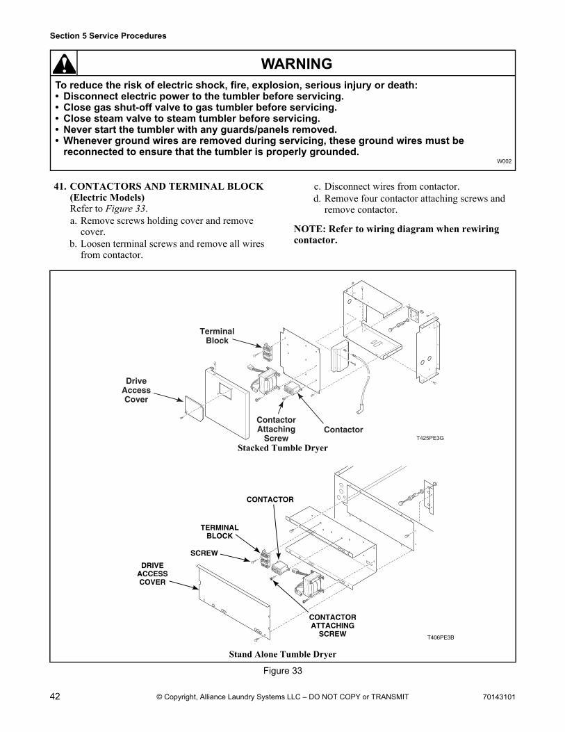
41. CONTACTORS AND TERMINAL BLOCK(Electric Models)Refer to Figure 33.a. Remove screws holding cover and remove
cover.b. Loosen terminal screws and remove all wires
from contactor.
c. Disconnect wires from contactor.d. Remove four contactor attaching screws and
remove contactor.
NOTE: Refer to wiring diagram when rewiring contactor.
Stacked Tumble Dryer
Stand Alone Tumble Dryer
Figure 33
T425PE3GContactor
ContactorAttaching
Screw
TerminalBlock
DriveAccessCover
T406PE3B
CONTACTOR
TERMINALBLOCK
SCREW
CONTACTORATTACHING
SCREW
DRIVEACCESSCOVER
70143101 43
Section 5 Service Procedures
To reduce the risk of electric shock, fire, explosion, serious injury or death:• Disconnect electric power to the tumbler before servicing.• Close gas shut-off valve to gas tumbler before servicing.• Close steam valve to steam tumbler before servicing.• Never start the tumbler with any guards/panels removed.• Whenever ground wires are removed during servicing, these ground wires must be
reconnected to ensure that the tumbler is properly grounded.W002
WARNING
© Copyright, Alliance Laundry Systems LLC – DO NOT COPY or TRANSMIT
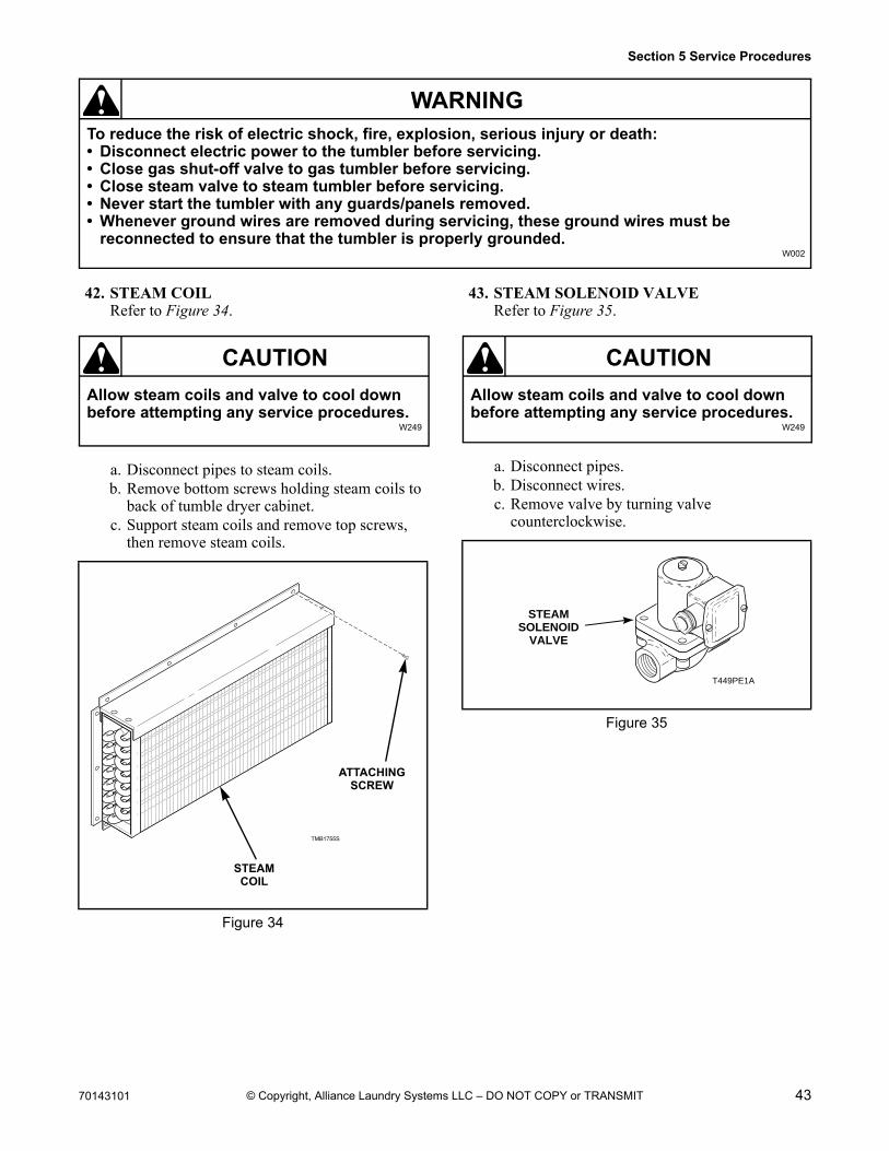
42. STEAM COILRefer to Figure 34.
a. Disconnect pipes to steam coils.b. Remove bottom screws holding steam coils to
back of tumble dryer cabinet.c. Support steam coils and remove top screws,
then remove steam coils.
43. STEAM SOLENOID VALVERefer to Figure 35.
a. Disconnect pipes.b. Disconnect wires.c. Remove valve by turning valve
counterclockwise.
Figure 34
Allow steam coils and valve to cool down before attempting any service procedures.
W249
CAUTION
TMB1755S
ATTACHINGSCREW
STEAMCOIL
Figure 35
Allow steam coils and valve to cool down before attempting any service procedures.
W249
CAUTION
T449PE1A
STEAMSOLENOID
VALVE
44 70143101
Section 5 Service Procedures
To reduce the risk of electric shock, fire, explosion, serious injury or death:• Disconnect electric power to the tumbler before servicing.• Close gas shut-off valve to gas tumbler before servicing.• Close steam valve to steam tumbler before servicing.• Never start the tumbler with any guards/panels removed.• Whenever ground wires are removed during servicing, these ground wires must be
reconnected to ensure that the tumbler is properly grounded.W002
WARNING
© Copyright, Alliance Laundry Systems LLC – DO NOT COPY or TRANSMIT
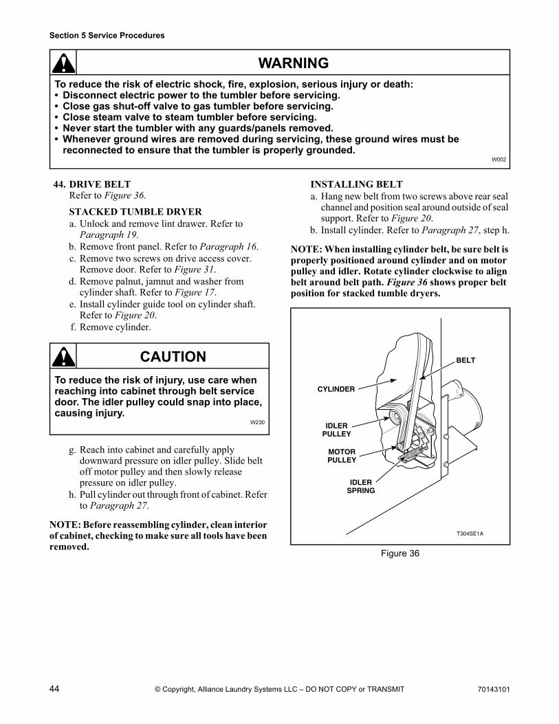
44. DRIVE BELTRefer to Figure 36.
STACKED TUMBLE DRYERa. Unlock and remove lint drawer. Refer to
Paragraph 19.b. Remove front panel. Refer to Paragraph 16.c. Remove two screws on drive access cover.
Remove door. Refer to Figure 31.d. Remove palnut, jamnut and washer from
cylinder shaft. Refer to Figure 17.e. Install cylinder guide tool on cylinder shaft.
Refer to Figure 20.f. Remove cylinder.
g. Reach into cabinet and carefully apply downward pressure on idler pulley. Slide belt off motor pulley and then slowly release pressure on idler pulley.
h. Pull cylinder out through front of cabinet. Refer to Paragraph 27.
NOTE: Before reassembling cylinder, clean interior of cabinet, checking to make sure all tools have been removed.
INSTALLING BELTa. Hang new belt from two screws above rear seal
channel and position seal around outside of seal support. Refer to Figure 20.
b. Install cylinder. Refer to Paragraph 27, step h.
NOTE: When installing cylinder belt, be sure belt is properly positioned around cylinder and on motor pulley and idler. Rotate cylinder clockwise to align belt around belt path. Figure 36 shows proper belt position for stacked tumble dryers.
To reduce the risk of injury, use care when reaching into cabinet through belt service door. The idler pulley could snap into place, causing injury.
W230
CAUTION
Figure 36
T304SE1A
MOTORPULLEY
CYLINDER
IDLERPULLEY
BELT
IDLERSPRING
70143101 45
Section 5 Service Procedures
To reduce the risk of electric shock, fire, explosion, serious injury or death:• Disconnect electric power to the tumbler before servicing.• Close gas shut-off valve to gas tumbler before servicing.• Close steam valve to steam tumbler before servicing.• Never start the tumbler with any guards/panels removed.• Whenever ground wires are removed during servicing, these ground wires must be
reconnected to ensure that the tumbler is properly grounded.W002
WARNING
© Copyright, Alliance Laundry Systems LLC – DO NOT COPY or TRANSMIT
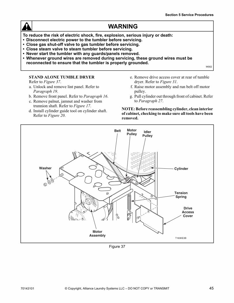
STAND ALONE TUMBLE DRYERRefer to Figure 37.a. Unlock and remove lint panel. Refer to
Paragraph 19.b. Remove front panel. Refer to Paragraph 16.c. Remove palnut, jamnut and washer from
trunnion shaft. Refer to Figure 17.d. Install cylinder guide tool on cylinder shaft.
Refer to Figure 20.
e. Remove drive access cover at rear of tumble dryer. Refer to Figure 31.
f. Raise motor assembly and run belt off motor pulley.
g. Pull cylinder out through front of cabinet. Refer to Paragraph 27.
NOTE: Before reassembling cylinder, clean interior of cabinet, checking to make sure all tools have been removed.
Figure 37
T163KE3B
Washer
DriveAccessCover
IdlerPulley
MotorPulley
Belt
Cylinder
TensionSpring
MotorAssembly
46 70143101
Section 5 Service Procedures
To reduce the risk of electric shock, fire, explosion, serious injury or death:• Disconnect electric power to the tumbler before servicing.• Close gas shut-off valve to gas tumbler before servicing.• Close steam valve to steam tumbler before servicing.• Never start the tumbler with any guards/panels removed.• Whenever ground wires are removed during servicing, these ground wires must be
reconnected to ensure that the tumbler is properly grounded.W002
WARNING
© Copyright, Alliance Laundry Systems LLC – DO NOT COPY or TRANSMIT
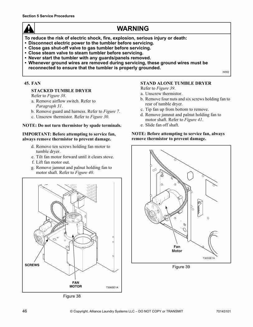
45. FAN
STACKED TUMBLE DRYERRefer to Figure 38.a. Remove airflow switch. Refer to
Paragraph 31.b. Remove guard and harness. Refer to Figure 7.c. Unscrew thermistor. Refer to Figure 30.
NOTE: Do not turn thermistor by spade terminals.
IMPORTANT: Before attempting to service fan, always remove thermistor to prevent damage.
d. Remove ten screws holding fan motor to tumble dryer.
e. Tilt fan motor forward until it clears stove.f. Lift fan motor out.g. Remove jamnut and palnut holding fan to
motor shaft. Refer to Figure 40.
STAND ALONE TUMBLE DRYERRefer to Figure 39.a. Unscrew thermistor.b. Remove four nuts and six screws holding fan to
rear of tumble dryer.c. Tip fan up from bottom to remove.d. Remove jamnut and palnut holding fan to
motor shaft. Refer to Figure 41.e. Slide fan off shaft.
NOTE: Before attempting to service fan, always remove thermistor to prevent damage.
Figure 38
T306SE1A
FANMOTOR
SCREWS Figure 39
T305SE1A
FanMotor
70143101 47
Section 5 Service Procedures
To reduce the risk of electric shock, fire, explosion, serious injury or death:• Disconnect electric power to the tumbler before servicing.• Close gas shut-off valve to gas tumbler before servicing.• Close steam valve to steam tumbler before servicing.• Never start the tumbler with any guards/panels removed.• Whenever ground wires are removed during servicing, these ground wires must be
reconnected to ensure that the tumbler is properly grounded.W002
WARNING
© Copyright, Alliance Laundry Systems LLC – DO NOT COPY or TRANSMIT
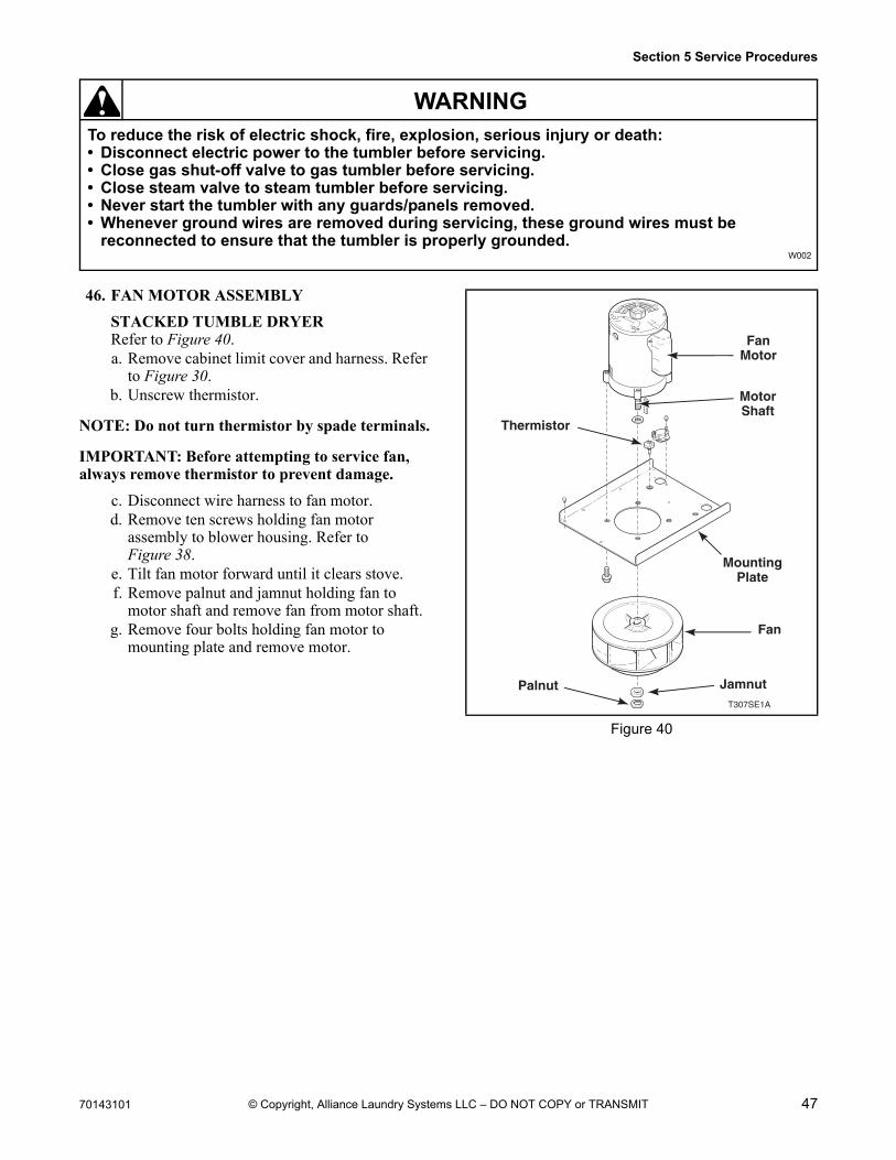
46. FAN MOTOR ASSEMBLY
STACKED TUMBLE DRYERRefer to Figure 40.a. Remove cabinet limit cover and harness. Refer
to Figure 30.b. Unscrew thermistor.
NOTE: Do not turn thermistor by spade terminals.
IMPORTANT: Before attempting to service fan, always remove thermistor to prevent damage.
c. Disconnect wire harness to fan motor.d. Remove ten screws holding fan motor
assembly to blower housing. Refer to Figure 38.
e. Tilt fan motor forward until it clears stove.f. Remove palnut and jamnut holding fan to
motor shaft and remove fan from motor shaft.g. Remove four bolts holding fan motor to
mounting plate and remove motor.
Figure 40
T307SE1A
FanMotor
MotorShaft
Fan
MountingPlate
Thermistor
Palnut Jamnut
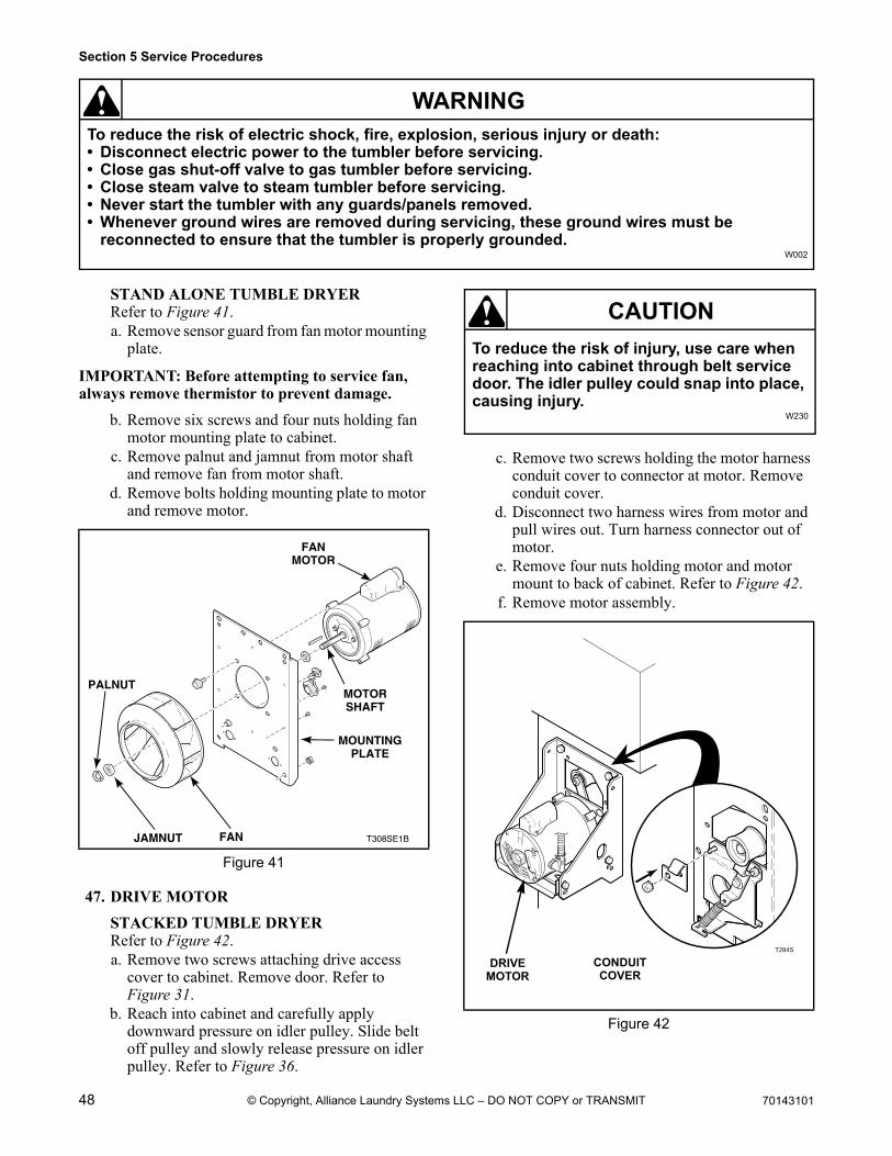
48 70143101
Section 5 Service Procedures
To reduce the risk of electric shock, fire, explosion, serious injury or death:• Disconnect electric power to the tumbler before servicing.• Close gas shut-off valve to gas tumbler before servicing.• Close steam valve to steam tumbler before servicing.• Never start the tumbler with any guards/panels removed.• Whenever ground wires are removed during servicing, these ground wires must be
reconnected to ensure that the tumbler is properly grounded.W002
WARNING
© Copyright, Alliance Laundry Systems LLC – DO NOT COPY or TRANSMIT
STAND ALONE TUMBLE DRYERRefer to Figure 41.a. Remove sensor guard from fan motor mounting
plate.
IMPORTANT: Before attempting to service fan, always remove thermistor to prevent damage.
b. Remove six screws and four nuts holding fan motor mounting plate to cabinet.
c. Remove palnut and jamnut from motor shaft and remove fan from motor shaft.
d. Remove bolts holding mounting plate to motor and remove motor.
47. DRIVE MOTOR
STACKED TUMBLE DRYERRefer to Figure 42.a. Remove two screws attaching drive access
cover to cabinet. Remove door. Refer to Figure 31.
b. Reach into cabinet and carefully apply downward pressure on idler pulley. Slide belt off pulley and slowly release pressure on idler pulley. Refer to Figure 36.
c. Remove two screws holding the motor harness conduit cover to connector at motor. Remove conduit cover.
d. Disconnect two harness wires from motor and pull wires out. Turn harness connector out of motor.
e. Remove four nuts holding motor and motor mount to back of cabinet. Refer to Figure 42.
f. Remove motor assembly.
Figure 41
T308SE1B
FANMOTOR
FAN
PALNUT
JAMNUT
MOTORSHAFT
MOUNTINGPLATE
Figure 42
To reduce the risk of injury, use care when reaching into cabinet through belt service door. The idler pulley could snap into place, causing injury.
W230
CAUTION
T284S
DRIVEMOTOR
CONDUIT COVER
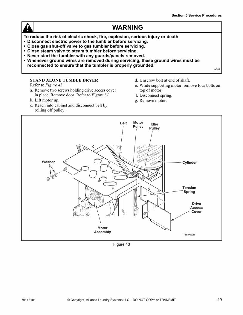
70143101 49
Section 5 Service Procedures
To reduce the risk of electric shock, fire, explosion, serious injury or death:• Disconnect electric power to the tumbler before servicing.• Close gas shut-off valve to gas tumbler before servicing.• Close steam valve to steam tumbler before servicing.• Never start the tumbler with any guards/panels removed.• Whenever ground wires are removed during servicing, these ground wires must be
reconnected to ensure that the tumbler is properly grounded.W002
WARNING
© Copyright, Alliance Laundry Systems LLC – DO NOT COPY or TRANSMIT
STAND ALONE TUMBLE DRYERRefer to Figure 43.a. Remove two screws holding drive access cover
in place. Remove door. Refer to Figure 31.b. Lift motor up.c. Reach into cabinet and disconnect belt by
rolling off pulley.
d. Unscrew bolt at end of shaft.e. While supporting motor, remove four bolts on
top of motor.f. Disconnect spring.g. Remove motor.
Figure 43
T163KE3B
Washer
DriveAccessCover
IdlerPulley
MotorPulley
Belt
Cylinder
TensionSpring
MotorAssembly
50 70143101
Section 5 Service Procedures
© Copyright, Alliance Laundry Systems LLC – DO NOT COPY or TRANSMIT
Notes
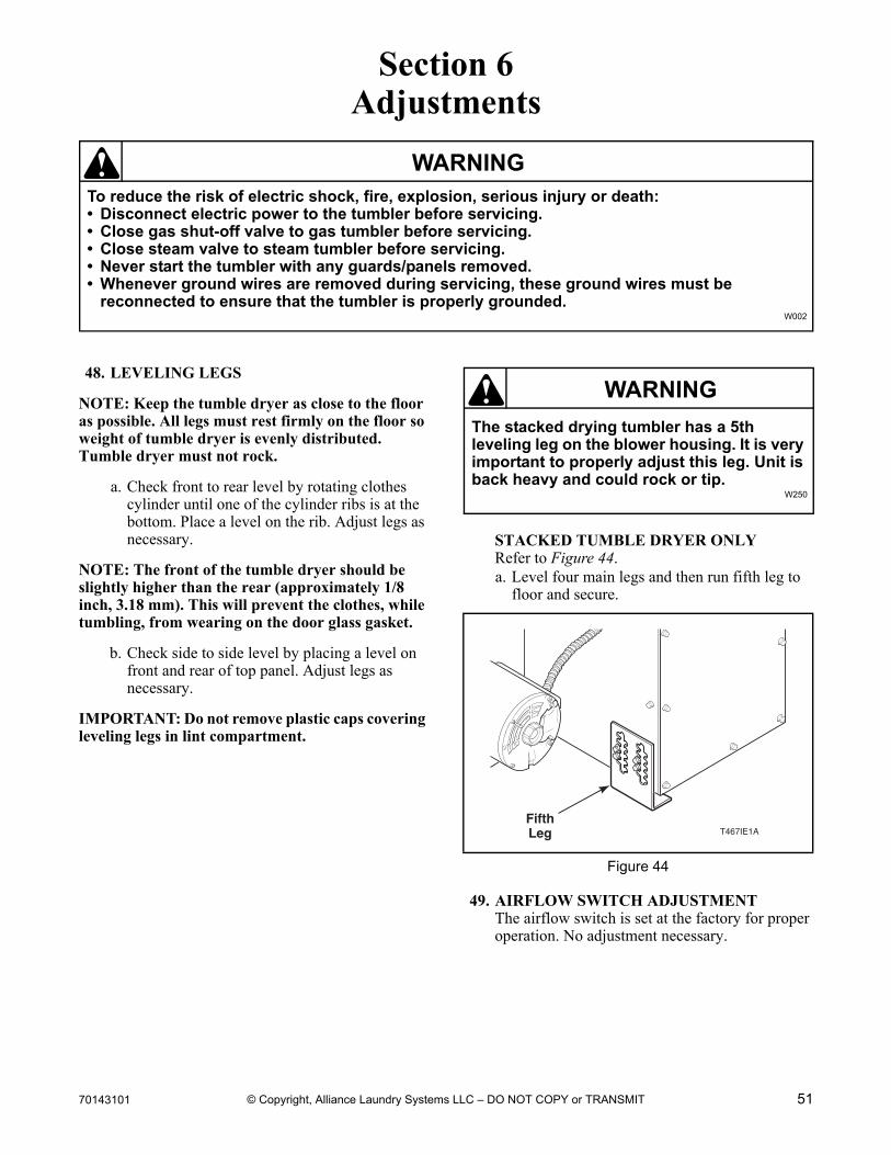
70143101 51
To reduce the risk of electric shock, fire, explosion, serious injury or death:• Disconnect electric power to the tumbler before servicing.• Close gas shut-off valve to gas tumbler before servicing.• Close steam valve to steam tumbler before servicing.• Never start the tumbler with any guards/panels removed.• Whenever ground wires are removed during servicing, these ground wires must be
reconnected to ensure that the tumbler is properly grounded.W002
WARNING
© Copyright, Alliance Laundry Systems LLC – DO NOT COPY or TRANSMIT
Section 6Adjustments
48. LEVELING LEGS
NOTE: Keep the tumble dryer as close to the floor as possible. All legs must rest firmly on the floor so weight of tumble dryer is evenly distributed. Tumble dryer must not rock.
a. Check front to rear level by rotating clothes cylinder until one of the cylinder ribs is at the bottom. Place a level on the rib. Adjust legs as necessary.
NOTE: The front of the tumble dryer should be slightly higher than the rear (approximately 1/8 inch, 3.18 mm). This will prevent the clothes, while tumbling, from wearing on the door glass gasket.
b. Check side to side level by placing a level on front and rear of top panel. Adjust legs as necessary.
IMPORTANT: Do not remove plastic caps covering leveling legs in lint compartment.
STACKED TUMBLE DRYER ONLYRefer to Figure 44.a. Level four main legs and then run fifth leg to
floor and secure.
49. AIRFLOW SWITCH ADJUSTMENTThe airflow switch is set at the factory for proper operation. No adjustment necessary.
Figure 44
The stacked drying tumbler has a 5th leveling leg on the blower housing. It is very important to properly adjust this leg. Unit is back heavy and could rock or tip.
W250
WARNING
T467IE1AFifthLeg
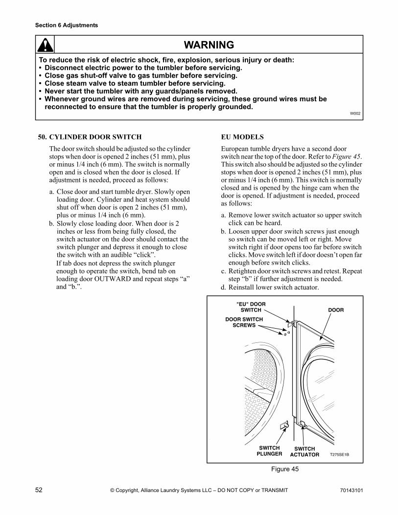
52 70143101
Section 6 Adjustments
To reduce the risk of electric shock, fire, explosion, serious injury or death:• Disconnect electric power to the tumbler before servicing.• Close gas shut-off valve to gas tumbler before servicing.• Close steam valve to steam tumbler before servicing.• Never start the tumbler with any guards/panels removed.• Whenever ground wires are removed during servicing, these ground wires must be
reconnected to ensure that the tumbler is properly grounded.W002
WARNING
© Copyright, Alliance Laundry Systems LLC – DO NOT COPY or TRANSMIT
50. CYLINDER DOOR SWITCH
The door switch should be adjusted so the cylinder stops when door is opened 2 inches (51 mm), plus or minus 1/4 inch (6 mm). The switch is normally open and is closed when the door is closed. If adjustment is needed, proceed as follows:
a. Close door and start tumble dryer. Slowly open loading door. Cylinder and heat system should shut off when door is open 2 inches (51 mm), plus or minus 1/4 inch (6 mm).
b. Slowly close loading door. When door is 2 inches or less from being fully closed, the switch actuator on the door should contact the switch plunger and depress it enough to close the switch with an audible “click”.If tab does not depress the switch plunger enough to operate the switch, bend tab on loading door OUTWARD and repeat steps “a” and “b.”.
EU MODELS
European tumble dryers have a second door switch near the top of the door. Refer to Figure 45. This switch also should be adjusted so the cylinder stops when door is opened 2 inches (51 mm), plus or minus 1/4 inch (6 mm). This switch is normally closed and is opened by the hinge cam when the door is opened. If adjustment is needed, proceed as follows:
a. Remove lower switch actuator so upper switch click can be heard.
b. Loosen upper door switch screws just enough so switch can be moved left or right. Move switch right if door opens too far before switch clicks. Move switch left if door doesn’t open far enough before switch clicks.
c. Retighten door switch screws and retest. Repeat step “b” if further adjustment is needed.
d. Reinstall lower switch actuator.
Figure 45
T275SE1B
"EU" DOORSWITCH
DOOR SWITCHSCREWS
SWITCHPLUNGER
SWITCHACTUATOR
DOOR
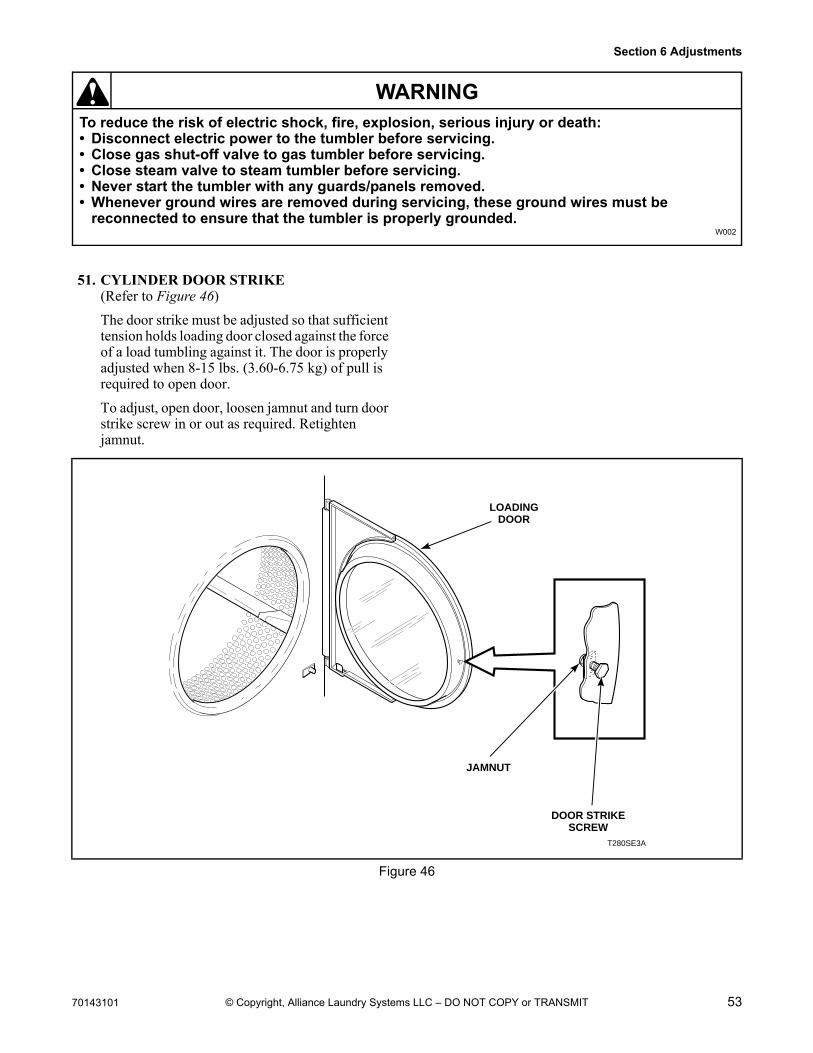
70143101 53
Section 6 Adjustments
To reduce the risk of electric shock, fire, explosion, serious injury or death:• Disconnect electric power to the tumbler before servicing.• Close gas shut-off valve to gas tumbler before servicing.• Close steam valve to steam tumbler before servicing.• Never start the tumbler with any guards/panels removed.• Whenever ground wires are removed during servicing, these ground wires must be
reconnected to ensure that the tumbler is properly grounded.W002
WARNING
© Copyright, Alliance Laundry Systems LLC – DO NOT COPY or TRANSMIT
51. CYLINDER DOOR STRIKE(Refer to Figure 46)
The door strike must be adjusted so that sufficient tension holds loading door closed against the force of a load tumbling against it. The door is properly adjusted when 8-15 lbs. (3.60-6.75 kg) of pull is required to open door.
To adjust, open door, loosen jamnut and turn door strike screw in or out as required. Retighten jamnut.
Figure 46
T280SE3A
LOADINGDOOR
JAMNUT
DOOR STRIKESCREW
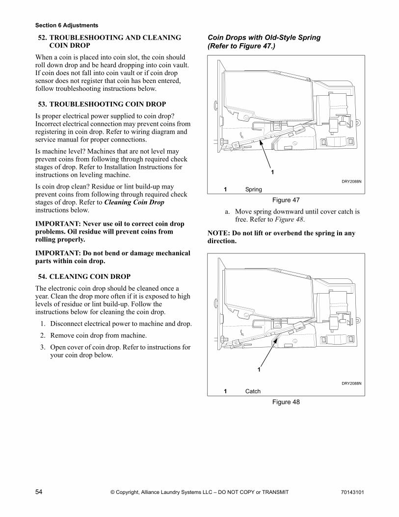
54 70143101
Section 6 Adjustments
© Copyright, Alliance Laundry Systems LLC – DO NOT COPY or TRANSMIT
52. TROUBLESHOOTING AND CLEANING COIN DROP
When a coin is placed into coin slot, the coin should roll down drop and be heard dropping into coin vault. If coin does not fall into coin vault or if coin drop sensor does not register that coin has been entered, follow troubleshooting instructions below.
53. TROUBLESHOOTING COIN DROP
Is proper electrical power supplied to coin drop? Incorrect electrical connection may prevent coins from registering in coin drop. Refer to wiring diagram and service manual for proper connections.
Is machine level? Machines that are not level may prevent coins from following through required check stages of drop. Refer to Installation Instructions for instructions on leveling machine.
Is coin drop clean? Residue or lint build-up may prevent coins from following through required check stages of drop. Refer to Cleaning Coin Drop instructions below.
IMPORTANT: Never use oil to correct coin drop problems. Oil residue will prevent coins from rolling properly.
IMPORTANT: Do not bend or damage mechanical parts within coin drop.
54. CLEANING COIN DROP
The electronic coin drop should be cleaned once a year. Clean the drop more often if it is exposed to high levels of residue or lint build-up. Follow the instructions below for cleaning the coin drop.
1. Disconnect electrical power to machine and drop.
2. Remove coin drop from machine.
3. Open cover of coin drop. Refer to instructions for your coin drop below.
Coin Drops with Old-Style Spring(Refer to Figure 47.)
a. Move spring downward until cover catch is free. Refer to Figure 48.
NOTE: Do not lift or overbend the spring in any direction.
DRY2088N
1 Spring
Figure 47
DRY2088N
1 Catch
Figure 48
DRY2088N
1
DRY2088N
1
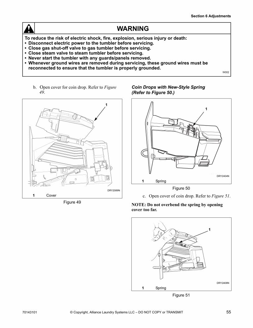
70143101 55
Section 6 Adjustments
To reduce the risk of electric shock, fire, explosion, serious injury or death:• Disconnect electric power to the tumbler before servicing.• Close gas shut-off valve to gas tumbler before servicing.• Close steam valve to steam tumbler before servicing.• Never start the tumbler with any guards/panels removed.• Whenever ground wires are removed during servicing, these ground wires must be
reconnected to ensure that the tumbler is properly grounded.W002
WARNING
© Copyright, Alliance Laundry Systems LLC – DO NOT COPY or TRANSMIT
b. Open cover for coin drop. Refer to Figure 49.
Coin Drops with New-Style Spring (Refer to Figure 50.)
Figure 50
c. Open cover of coin drop. Refer to Figure 51.
NOTE: Do not overbend the spring by opening cover too far.
Figure 51
DRY2089N
1 Cover
Figure 49
1
DRY2404N
1 Spring
DRY2408N
1 Spring
DRY2404N
1
DRY2408N
1
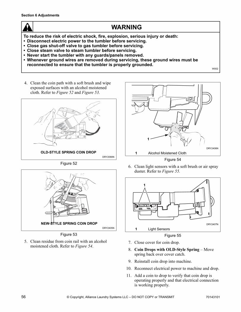
56 70143101
Section 6 Adjustments
To reduce the risk of electric shock, fire, explosion, serious injury or death:• Disconnect electric power to the tumbler before servicing.• Close gas shut-off valve to gas tumbler before servicing.• Close steam valve to steam tumbler before servicing.• Never start the tumbler with any guards/panels removed.• Whenever ground wires are removed during servicing, these ground wires must be
reconnected to ensure that the tumbler is properly grounded.W002
WARNING
© Copyright, Alliance Laundry Systems LLC – DO NOT COPY or TRANSMIT
4. Clean the coin path with a soft brush and wipe exposed surfaces with an alcohol moistened cloth. Refer to Figure 52 and Figure 53.
.
5. Clean residue from coin rail with an alcohol moistened cloth. Refer to Figure 54.
6. Clean light sensors with a soft brush or air spray duster. Refer to Figure 55.
7. Close cover for coin drop.
8. Coin Drops with OLD-Style Spring – Move spring back over cover catch.
9. Reinstall coin drop into machine.
10. Reconnect electrical power to machine and drop.
11. Add a coin to drop to verify that coin drop is operating properly and that electrical connection is working properly.
DRY2090N
Figure 52
DRY2405N
Figure 53
DRY2090N
OLD-STYLE SPRING COIN DROP
DRY2405N
NEW-STYLE SPRING COIN DROP
DRY2406N
1 Alcohol Moistened Cloth
Figure 54
DRY2407N
1 Light Sensors
Figure 55
1
11
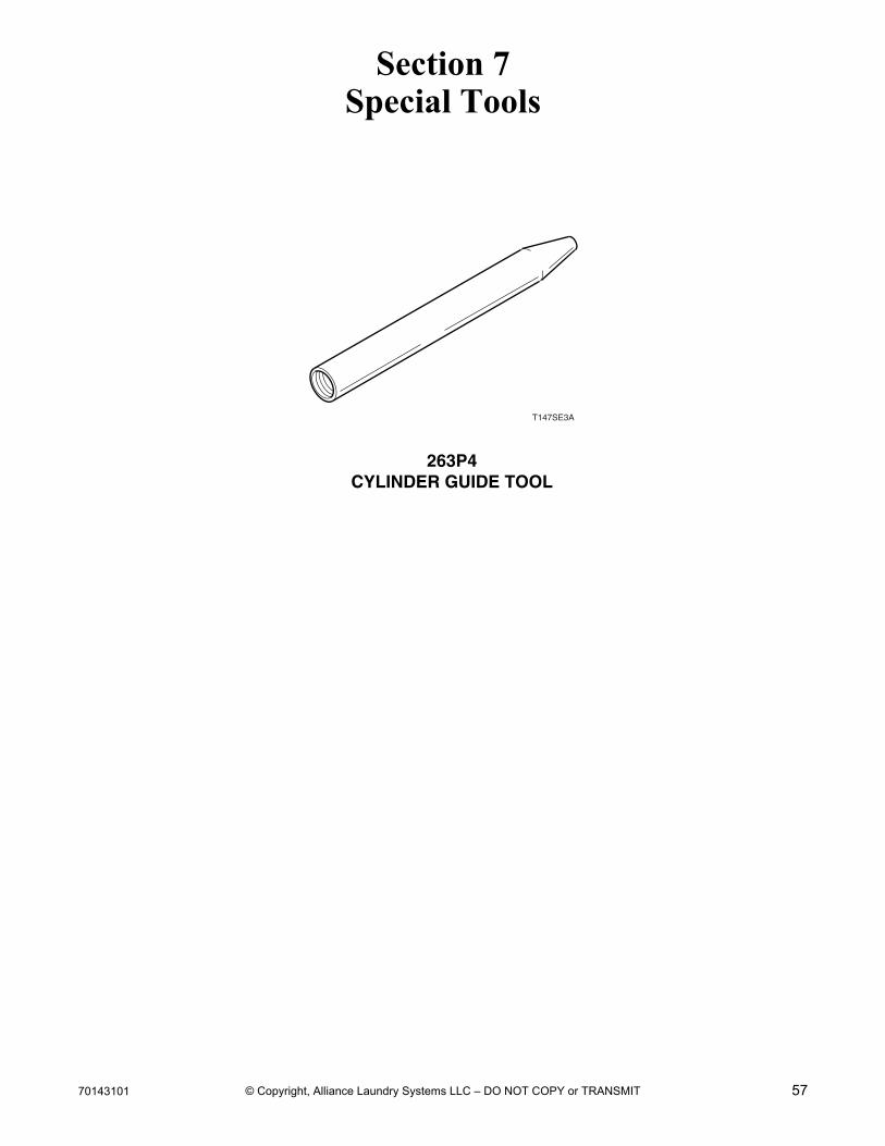
70143101 57© Copyright, Alliance Laundry Systems LLC – DO NOT COPY or TRANSMIT
Section 7Special Tools
263P4CYLINDER GUIDE TOOL
T147SE3A

58 70143101
Section 7
© Copyright, Alliance Laundry Systems LLC – DO NOT COPY or TRANSMIT
Notes