Embed Size (px)
Citation preview
Tumble Finishing of CH Capsules
20th Target Fabrication Meeting Santa Fe, May 24, 2012
T. Suratwala, R. Steele, M. Feit, M. Stadermann, J. Fair, K. Wu Lawrence Livermore National Laboratory
K. Moreno, K. Chen, K. Youngblood, A. Nikroo General Atomics LLNL-PRES-502235
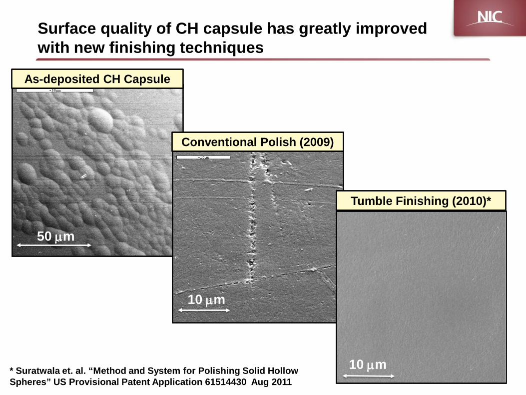
Surface quality of CH capsule has greatly improved with new finishing techniques
As-deposited CH Capsule
Conventional Polish (2009)
Tumble Finishing (2010)*
50 µm
10 µm
10 µm * Suratwala et. al. “Method and System for Polishing Solid Hollow Spheres” US Provisional Patent Application 61514430 Aug 2011
Wegner, NIC Review, December 9, 2009 3 NIF-1209-17951.ppt
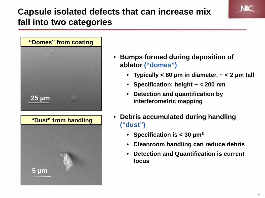
Capsule isolated defects that can increase mix fall into two categories
• Bumps formed during deposition of ablator (“domes”)
• Typically < 80 µm in diameter, ~ < 2 µm tall • Specification: height ~ < 200 nm • Detection and quantification by
interferometric mapping
• Debris accumulated during handling (“dust”)
• Specification is < 30 µm3
• Cleanroom handling can reduce debris • Detection and Quantification is current
focus
50 µm 25 µm
5 µm
“Domes” from coating
“Dust” from handling
4
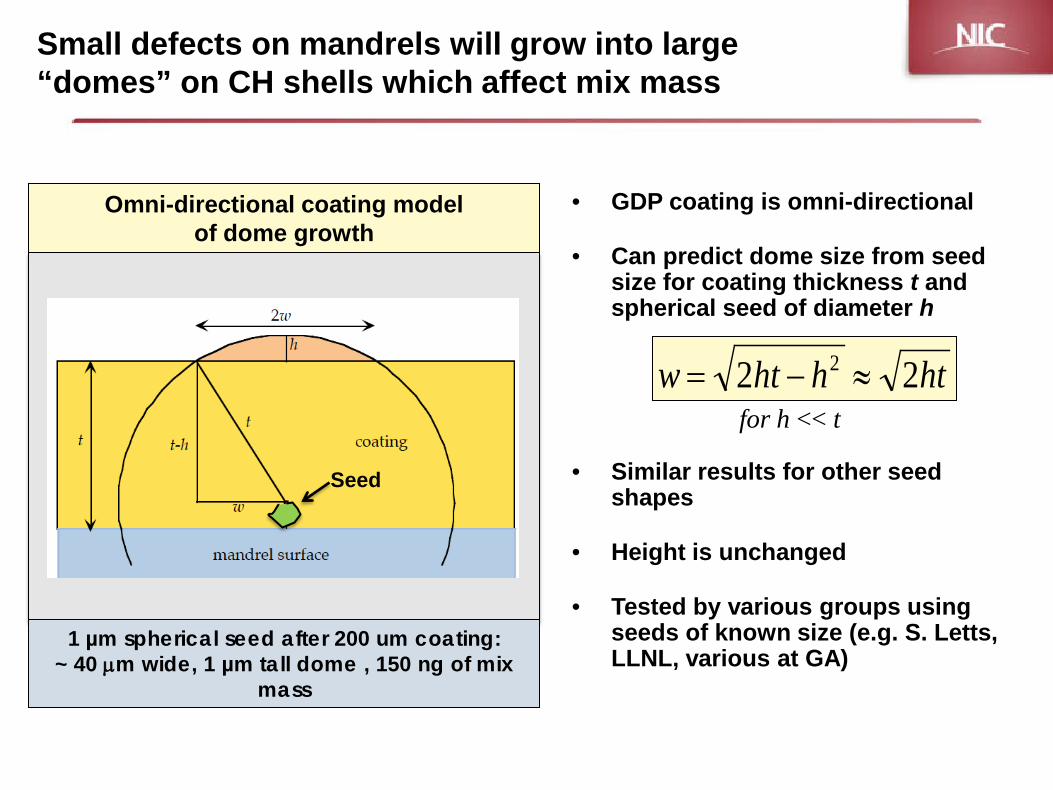
Small defects on mandrels will grow into large “domes” on CH shells which affect mix mass
• GDP coating is omni-directional
• Can predict dome size from seed size for coating thickness t and spherical seed of diameter h
• Similar results for other seed shapes
• Height is unchanged
• Tested by various groups using seeds of known size (e.g. S. Letts, LLNL, various at GA)
Omni-directional coating model of dome growth
1 µm spherical seed after 200 um coating: ~ 40 µm wide, 1 µm tall dome , 150 ng of mix
mass
hthhtw 22 2 ≈−=for h << t
Seed
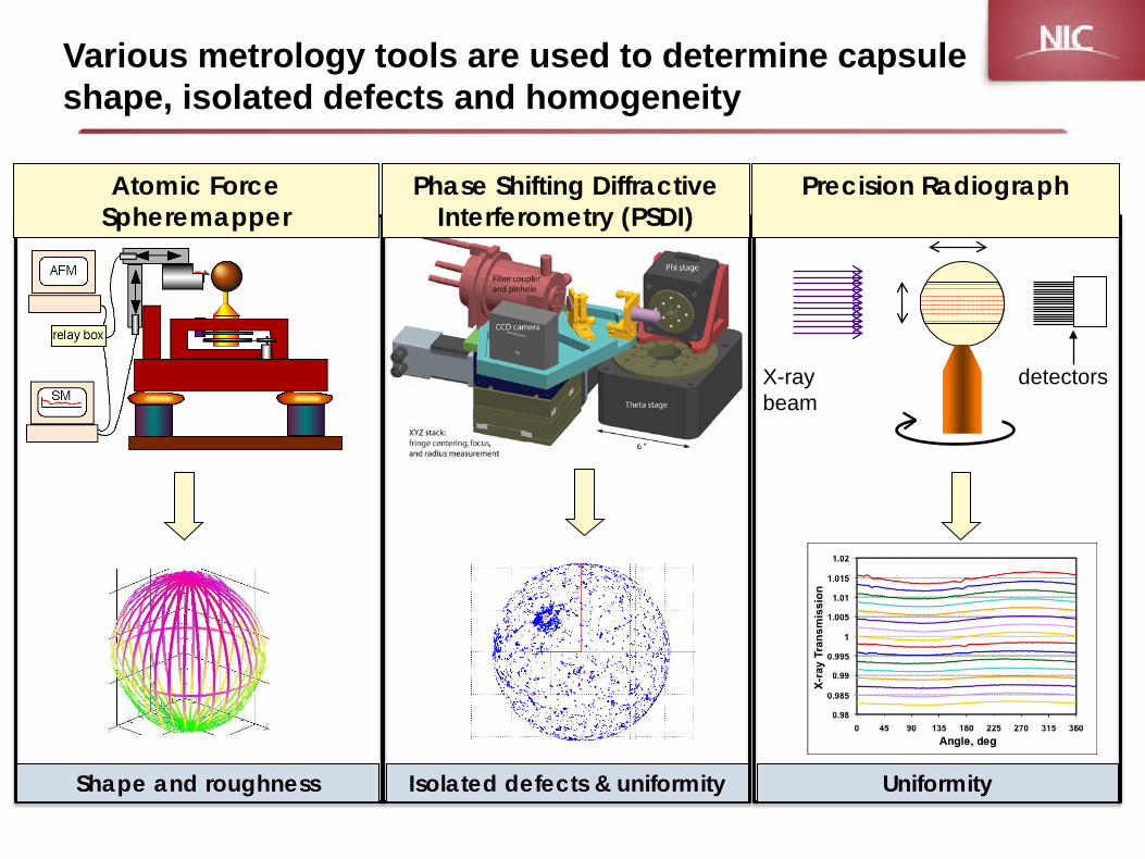
Surface: AFM
detectors X-ray beam
Isolated defects & uniformity Uniformity Shape and roughness
Various metrology tools are used to determine capsule shape, isolated defects and homogeneity
Phase Shifting Diffractive Interferometry (PSDI)
Precision Radiograph
Atomic Force Spheremapper
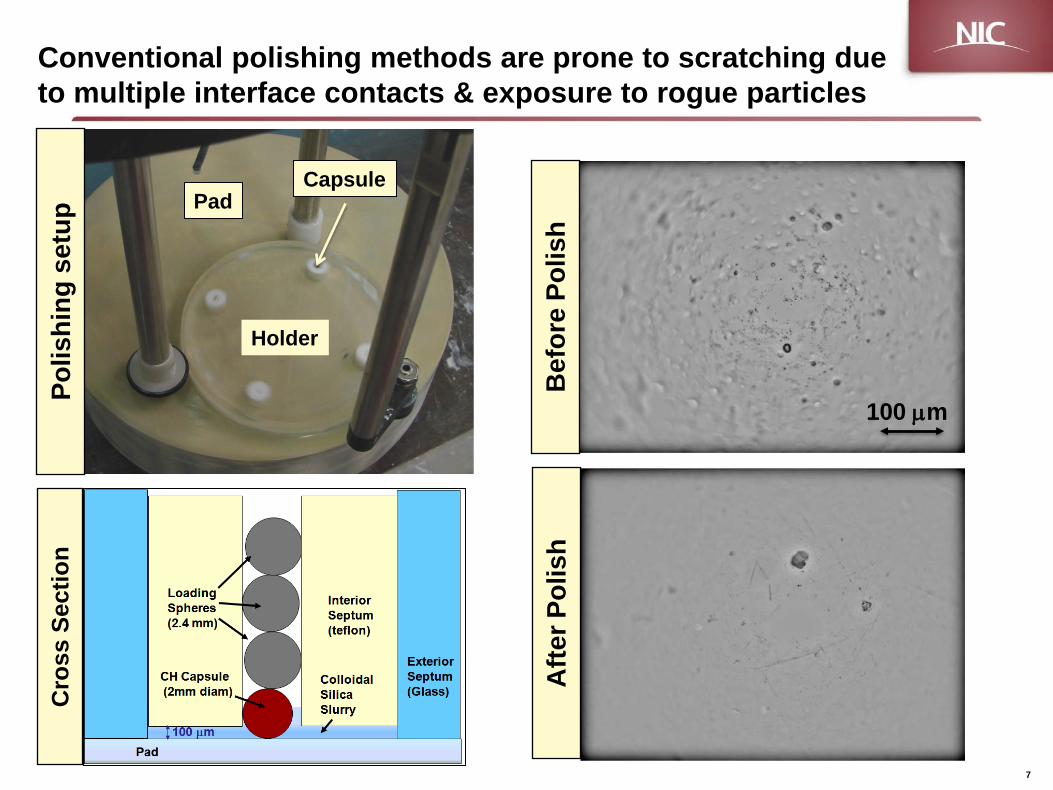
Conventional polishing methods are prone to scratching due to multiple interface contacts & exposure to rogue particles
7
Cro
ss S
ectio
n Po
lishi
ng s
etup
Pad
Holder
Capsule
Bef
ore
Polis
h A
fter P
olis
h
100 µm
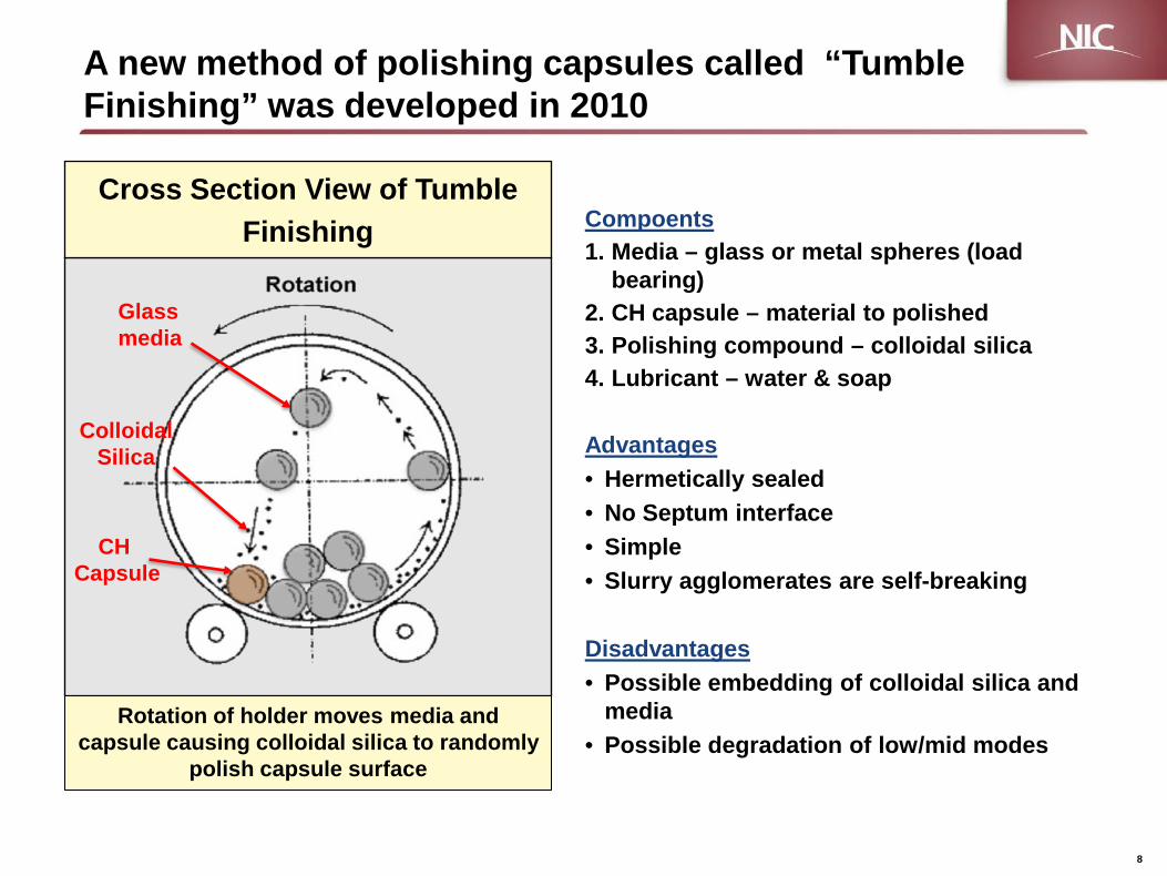
A new method of polishing capsules called “Tumble Finishing” was developed in 2010
Compoents 1. Media – glass or metal spheres (load
bearing) 2. CH capsule – material to polished 3. Polishing compound – colloidal silica 4. Lubricant – water & soap
Advantages • Hermetically sealed • No Septum interface • Simple • Slurry agglomerates are self-breaking
Disadvantages • Possible embedding of colloidal silica and
media • Possible degradation of low/mid modes
8
CH Capsule
Glass media
Colloidal Silica
Rotation of holder moves media and capsule causing colloidal silica to randomly
polish capsule surface
Cross Section View of Tumble Finishing
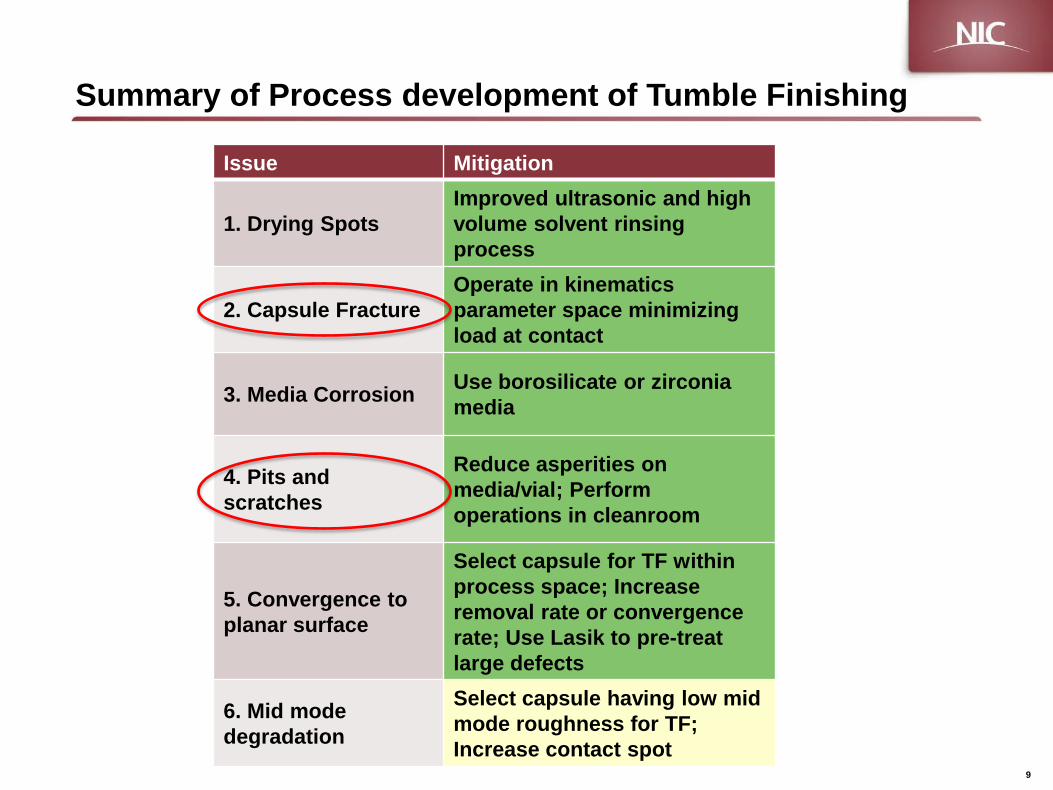
Summary of Process development of Tumble Finishing
9
Issue Mitigation
1. Drying Spots Improved ultrasonic and high volume solvent rinsing process
2. Capsule Fracture Operate in kinematics parameter space minimizing load at contact
3. Media Corrosion Use borosilicate or zirconia media
4. Pits and scratches
Reduce asperities on media/vial; Perform operations in cleanroom
5. Convergence to planar surface
Select capsule for TF within process space; Increase removal rate or convergence rate; Use Lasik to pre-treat large defects
6. Mid mode degradation
Select capsule having low mid mode roughness for TF; Increase contact spot
10
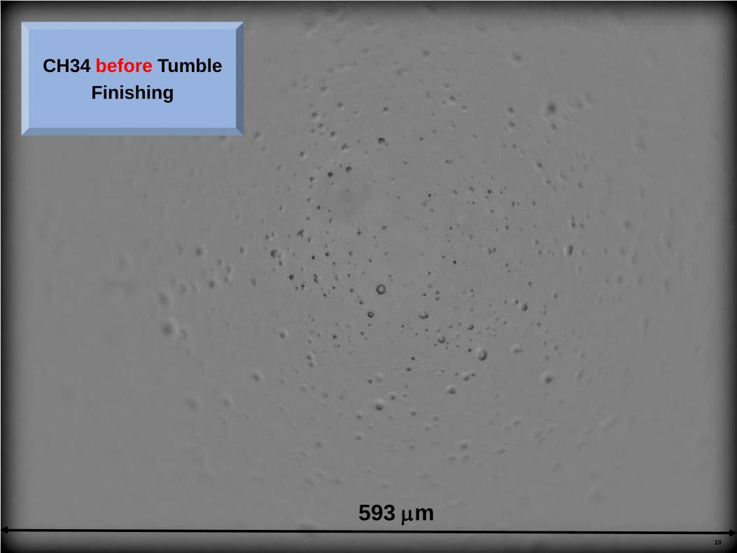
593 µm
CH34 before Tumble Finishing
11
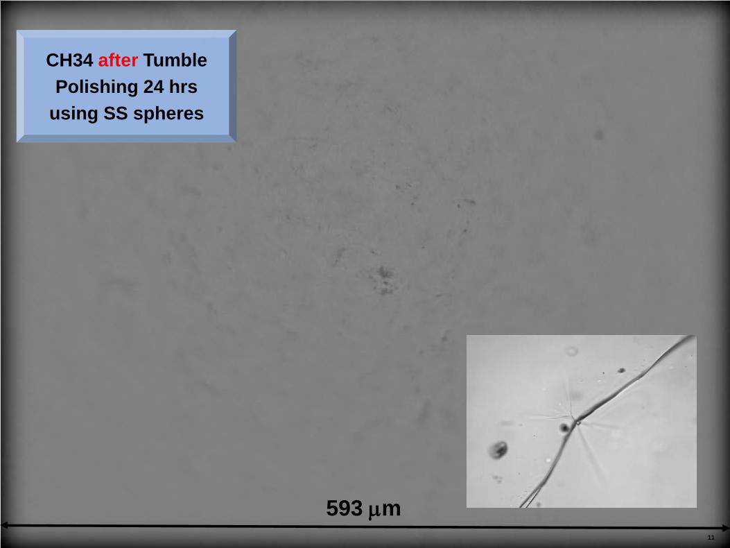
593 µm
CH34 after Tumble Polishing 24 hrs
using SS spheres
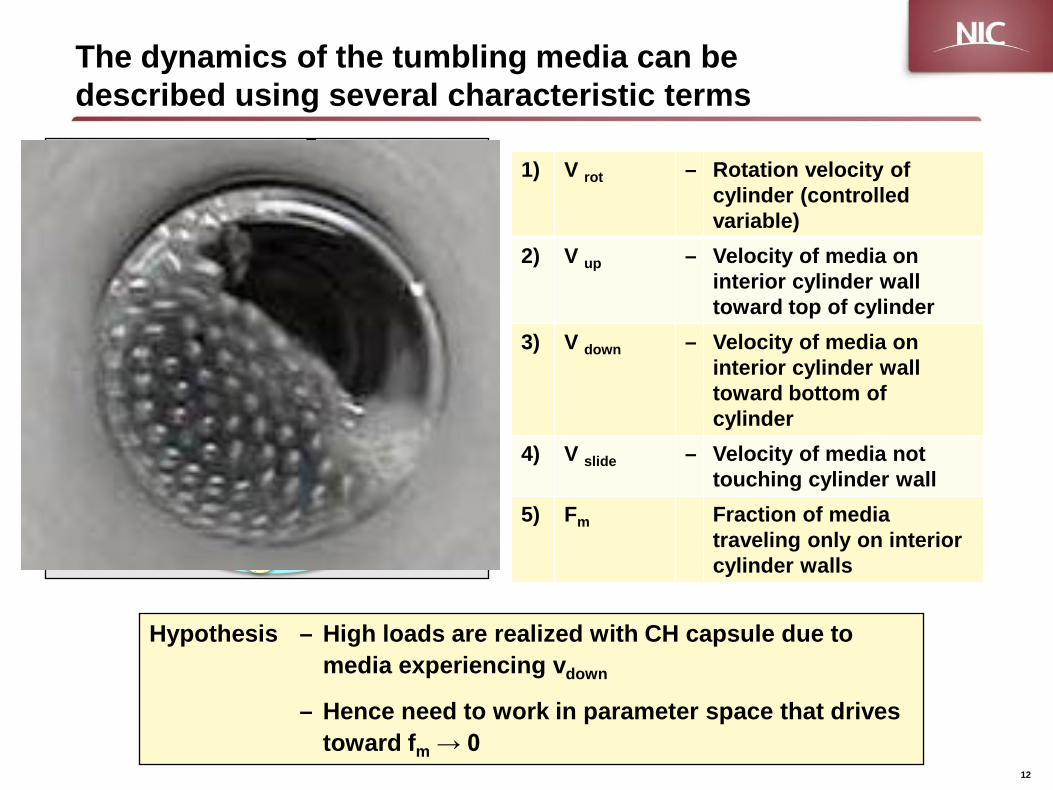
The dynamics of the tumbling media can be described using several characteristic terms
12
Hypothesis – High loads are realized with CH capsule due to media experiencing vdown
– Hence need to work in parameter space that drives toward fm → 0
1) V rot – Rotation velocity of cylinder (controlled variable)
2) V up – Velocity of media on interior cylinder wall toward top of cylinder
3) V down – Velocity of media on interior cylinder wall toward bottom of cylinder
4) V slide – Velocity of media not touching cylinder wall
5) Fm Fraction of media traveling only on interior cylinder walls
V slide
V down
Fm
V up
V rot
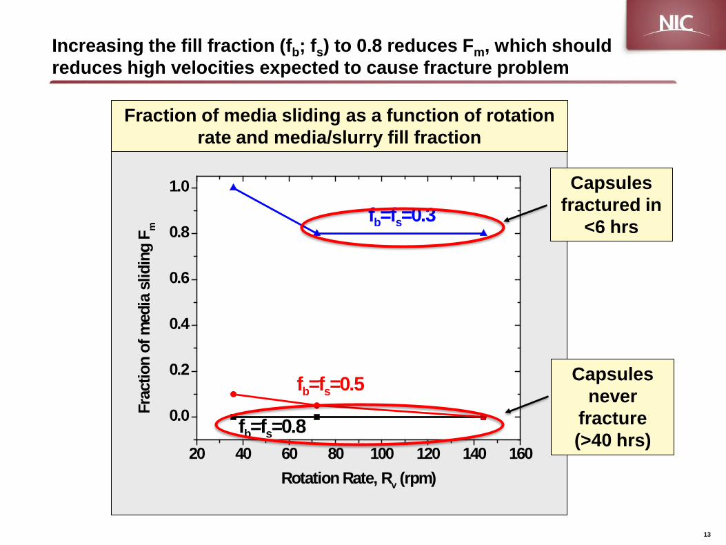
Increasing the fill fraction (fb; fs) to 0.8 reduces Fm, which should reduces high velocities expected to cause fracture problem
13
20 40 60 80 100 120 140 160
0.0
0.2
0.4
0.6
0.8
1.0
fb=fs=0.8
fb=fs=0.5
Fr
actio
n of
med
ia s
lidin
g F m
Rotation Rate, Rv (rpm)
fb=fs=0.3Capsules
fractured in <6 hrs
Capsules never
fracture (>40 hrs)
Fraction of media sliding as a function of rotation rate and media/slurry fill fraction
14
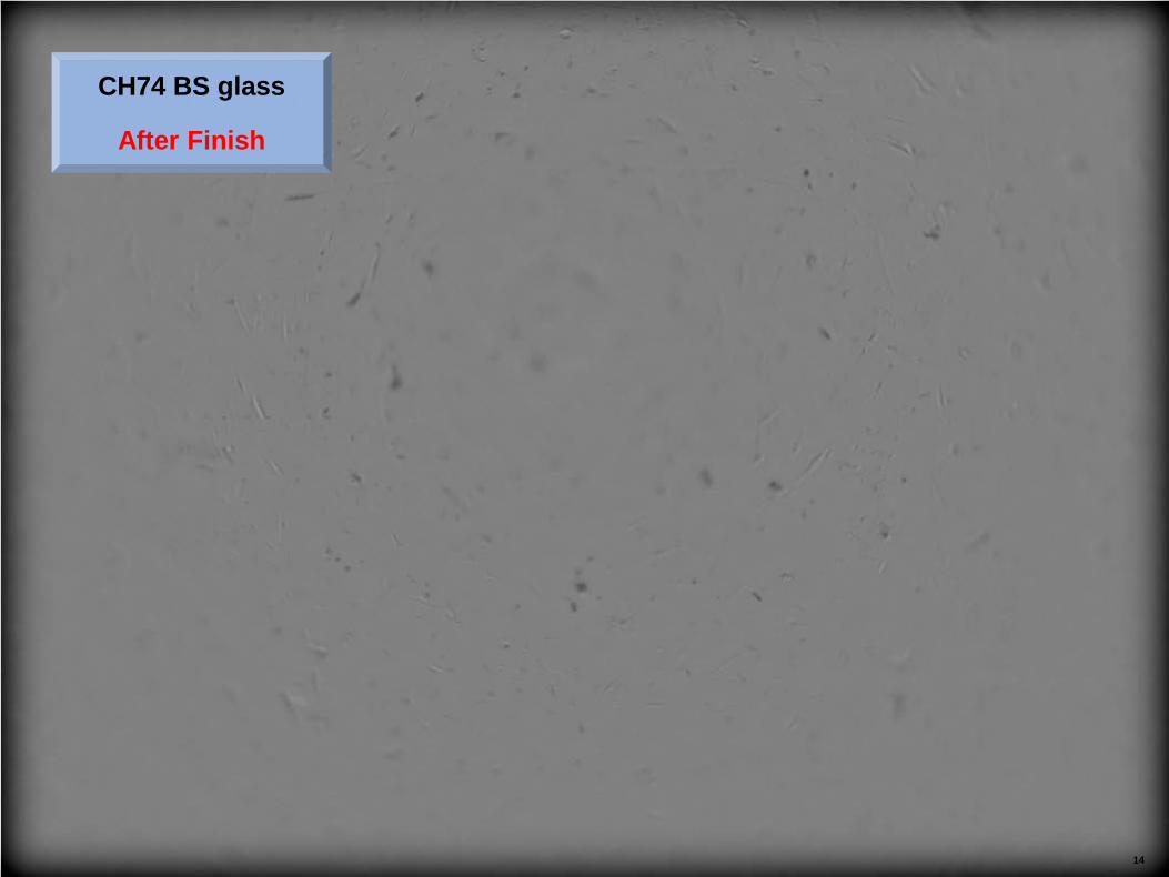
CH74 BS glass
After Finish
15
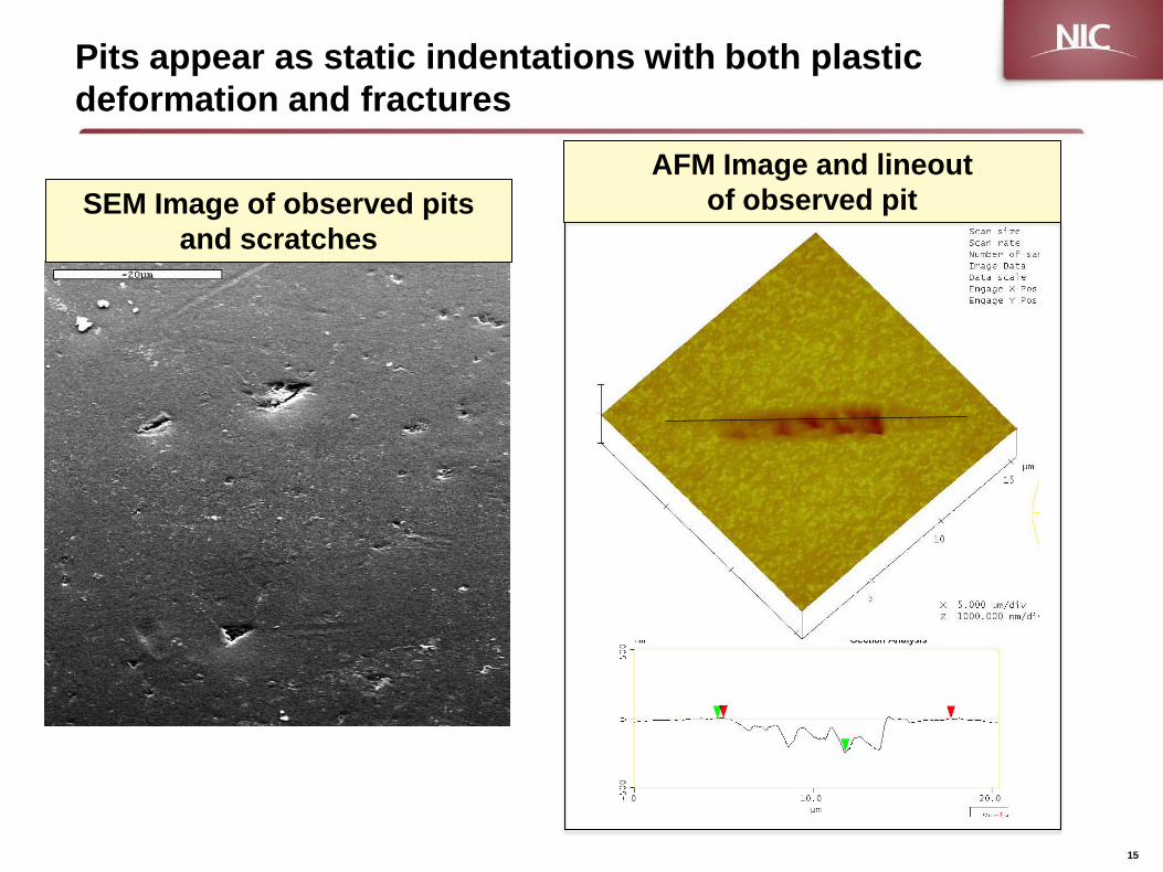
Pits appear as static indentations with both plastic deformation and fractures
SEM Image of observed pits and scratches
AFM Image and lineout of observed pit

CH90 BS Glass
Polished media/vial
After finishing
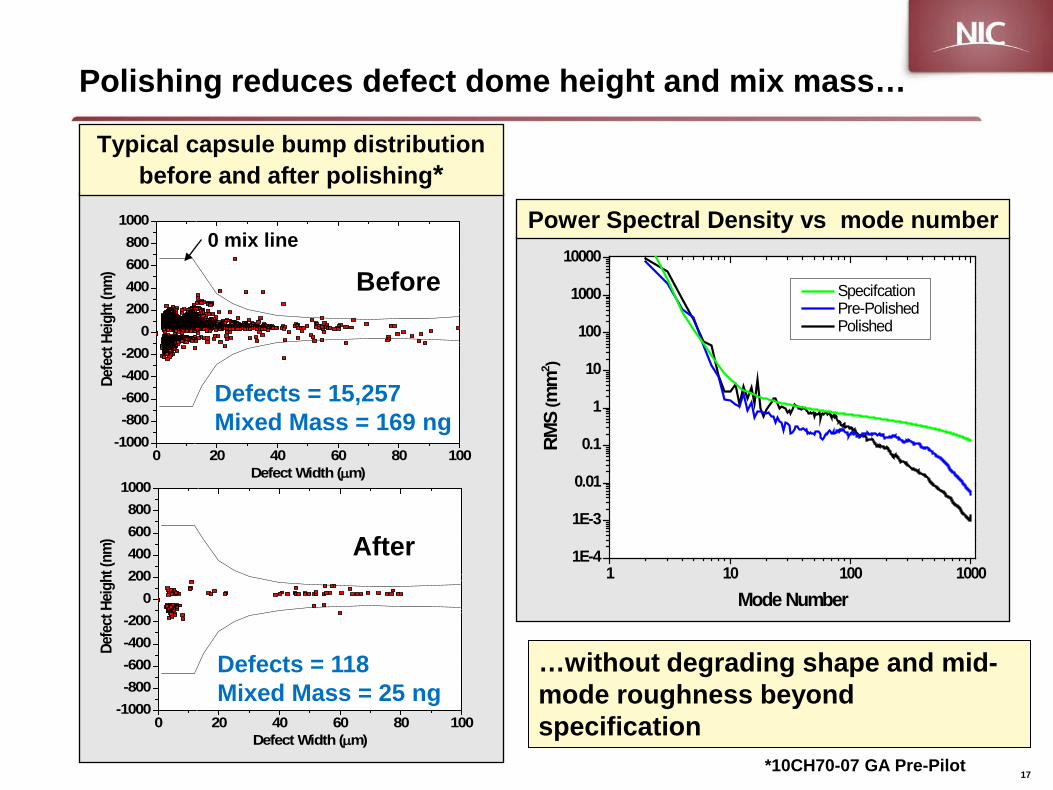
Polishing reduces defect dome height and mix mass…
Typical capsule bump distribution before and after polishing*
Power Spectral Density vs mode number
0 20 40 60 80 100-1000-800-600-400-200
0200400600800
1000
Defe
ct H
eight
(nm
)
Defect Width (µm)
0 20 40 60 80 100-1000-800-600-400-200
0200400600800
1000
Defe
ct H
eight
(nm
)
Defect Width (µm)
*10CH70-07 GA Pre-Pilot
After
Before
Defects = 15,257 Mixed Mass = 169 ng
Defects = 118 Mixed Mass = 25 ng
0 mix line
1 10 100 10001E-4
1E-3
0.01
0.1
1
10
100
1000
10000
Specifcation Pre-Polished Polished
RMS
(mm
2 )
Mode Number
17
…without degrading shape and mid-mode roughness beyond specification

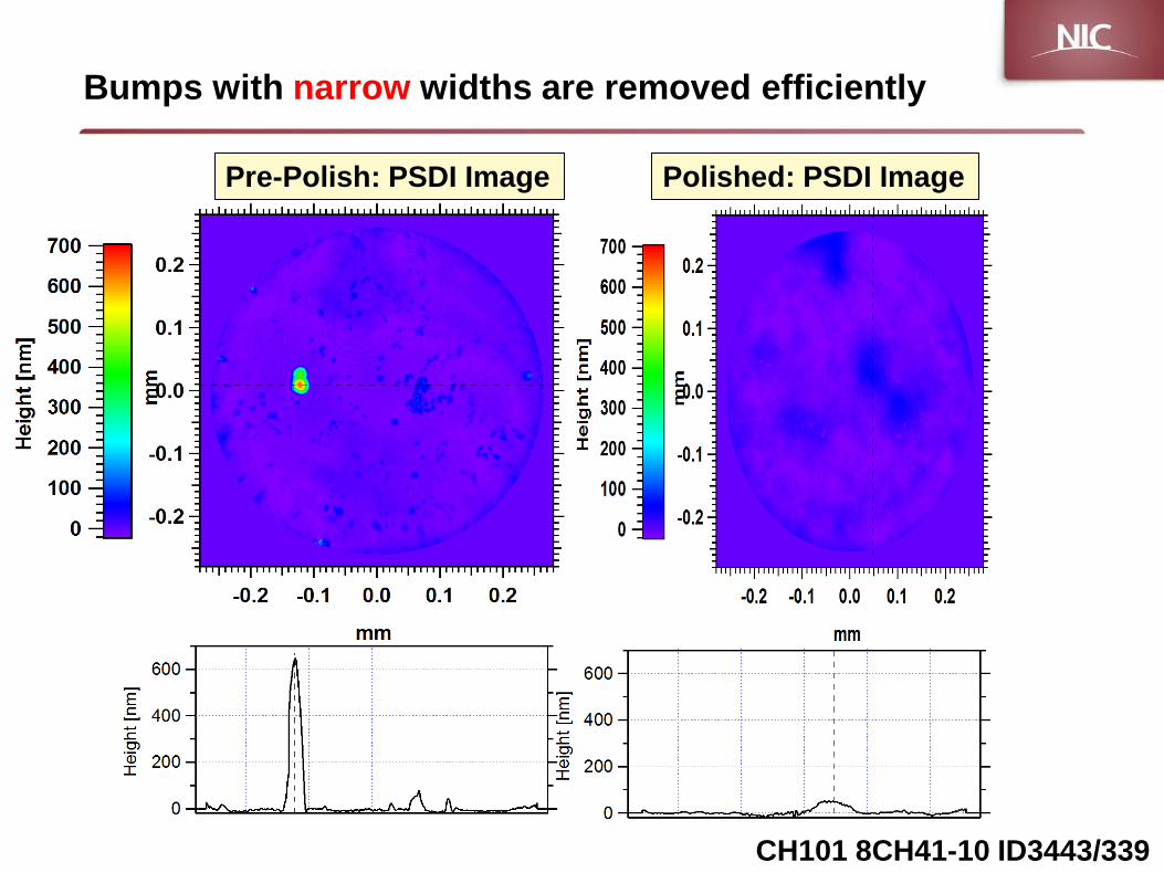
CH101 8CH41-10 ID3443/339
Bumps with narrow widths are removed efficiently
Pre-Polish: PSDI Image Polished: PSDI Image
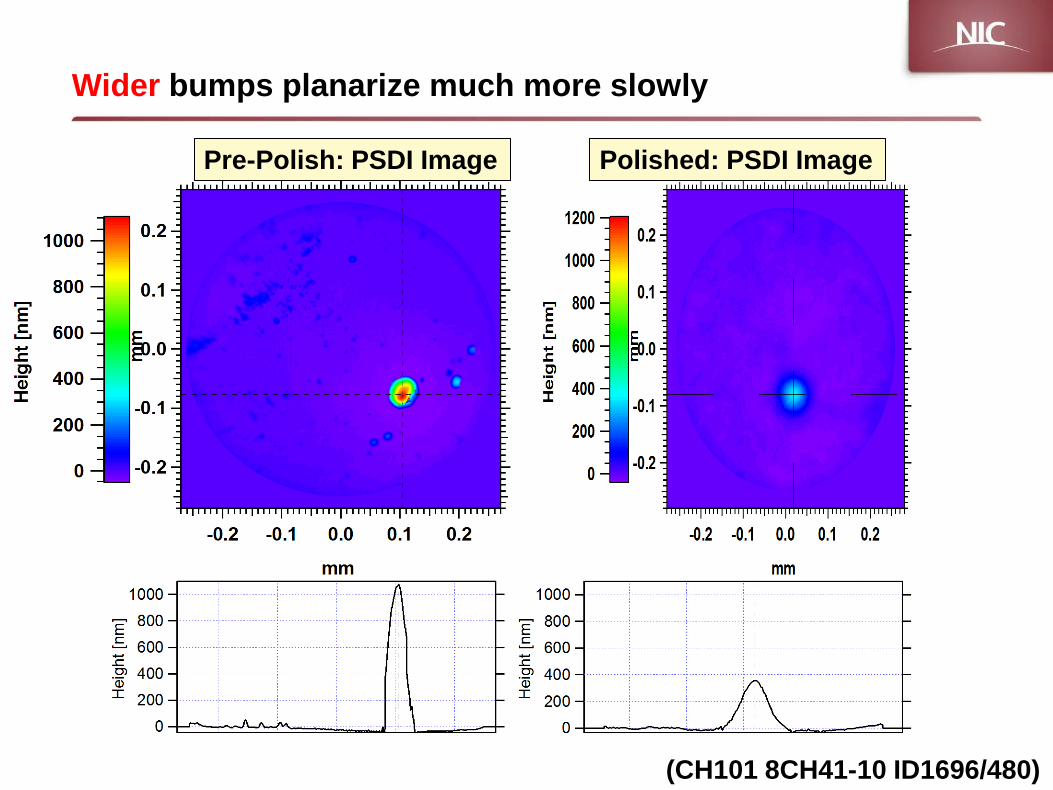
Wider bumps planarize much more slowly
Pre-Polish: PSDI Image
(CH101 8CH41-10 ID1696/480)
Polished: PSDI Image
Official Use Only- Proprietary
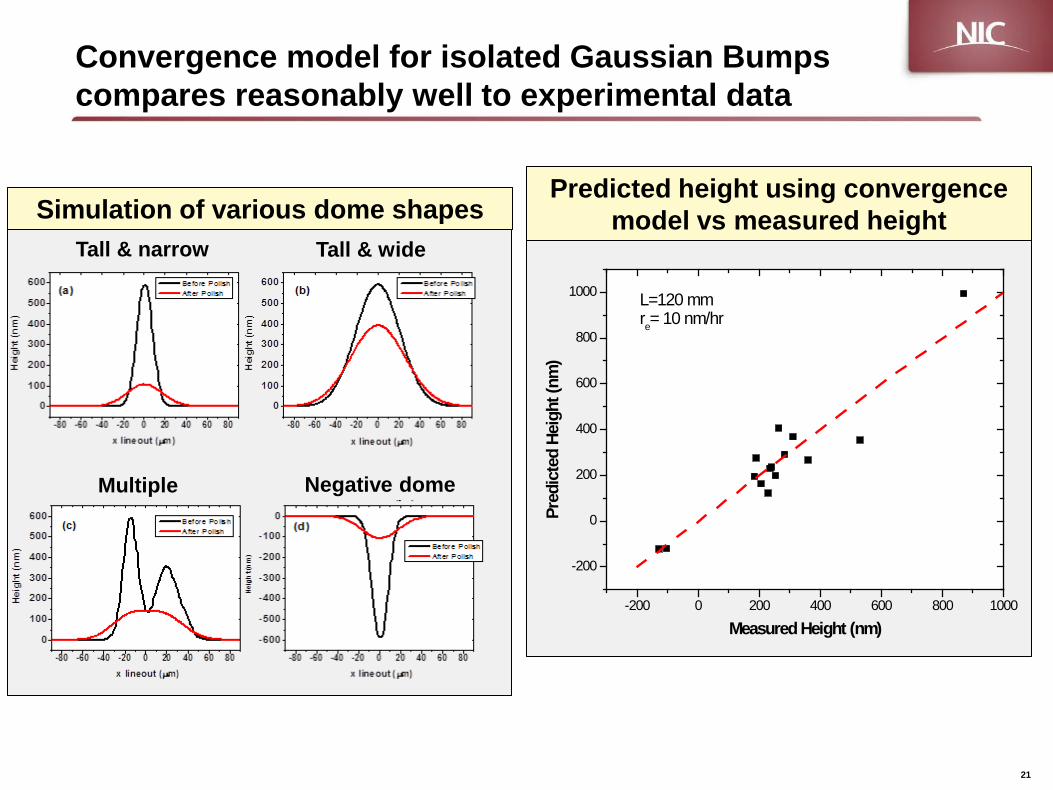
Convergence model for isolated Gaussian Bumps compares reasonably well to experimental data
21
Predicted height using convergence model vs measured height
-200 0 200 400 600 800 1000
-200
0
200
400
600
800
1000
Pred
icte
d He
ight
(nm
)
Measured Height (nm)
L=120 mmre= 10 nm/hr
Simulation of various dome shapes Tall & narrow Tall & wide
Multiple Negative dome
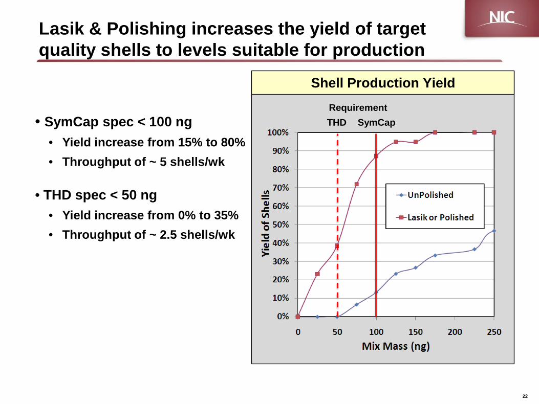
Shell Production Yield
Lasik & Polishing increases the yield of target quality shells to levels suitable for production
SymCap THD • SymCap spec < 100 ng • Yield increase from 15% to 80% • Throughput of ~ 5 shells/wk
• THD spec < 50 ng • Yield increase from 0% to 35% • Throughput of ~ 2.5 shells/wk
22
Requirement

Surface quality of CH capsule has greatly improved with new finishing techniques
As-deposited CH Capsule
Conventional Polish (2009)
Tumble Finishing (2010)*
50 µm
10 µm
10 µm * Suratwala et. al. “Method and System for Polishing Solid Hollow Spheres” US Provisional Patent Application 61514430 Aug 2011