Embed Size (px)
Citation preview
Tucuon E/ectric Puwer Cump-, P.O. Box 711, Tucson, AZ 85702
One South Church Avenue, Suite 200, Tucson, Arizona 85701
January 3 1,2008
Docket Control Arizona Corporation Commission 1200 West Washington Street Phoenix, AZ 85007
Re: Docket No. E-00000D-07-0376
Docket Control:
Enclosed please find an original and thirteen copies of Tucson Electric Power Company’s (“TEP”) “Ten-Year Plans” pursuant to Title 40, Chapter 2, Article 6.2, “Power Plant and Transmission Line Siting Committee”, of the Arizona Revised Statutes. TEP’s RMR study, per Staff request, is being provided to Commission Staff directly.
Enclosed is an additional copy of the filing that the Company requests you date-stamp and return in the self-addressed, stamped envelope for our files.
Sincerely,
Jessica Bryne Regulatory Services
cc: Ernest Johnson, ACC Prem Bahl, ACC Ed Beck, TEP Compliance, ACC (cover letter only)
A UniSource Energy Company
TUCSON ELECTRIC POWER COMPANY
TEN YEAR PLAN
FOR YEARS
2008-2017
SUBMITTED TO THE
ARIZONA CORPORATION COMMISSION
JANUARY 2008
DOCKET NO: E-000OOD-07-0376
-1- 01/ 28/ 2008
CONTENTS
INTRODUCTION .................................................................................................................................................................. 3
PLANNED TRANSMISSION FACILITIES DESCRIPTIONS .................................................................................... 8
EHV FACILITIES ................................................................................................................................................................... 8 Interconnection of Westwing - South 345 kV with,future Hassyampa - Pinal West 500 kV line via new Pinal West
Pinal South Substation to Tortolita Substation ......... Tortolita Substation to Vail Substatio Tortolita Substation to Winchester Substation Winchester Substation to Vail Substat
500/345 kV Substation ............................................................. .............................................................. 8
..............................................
.................... 13 ................................. 14
Vail Substation to South Substation - 2"d circuit .......................................... Springerville Substation to Greenlee Substation - 2"d circuit ..................
Westwing Substation to South Substation - 2"d circuit ...... Tortolita Substation to South Substation ........................................
TEP-Unisource Energy Services 345 .......................................................
.................................................... .............................................................. ateway Substation to Comision Fe (CFE) (2 ckts.) ........................
HV FACILITIES ................................................................................................................................................................... 19 Irvington Substation to East Loop Substation (through 22nd Street Substation) ........................................................... 19
Substations), tapping the Roberts-East Loop line for new Harrison substation.. .............................. East Loop Substation to Northeast Substation (through Snyder Substation) ............. Loop existing West Ina Substation to Tucson Station line through Del Cerro formerly Sweetwater) Substation ....... 22 Loop existing Vail Substation to East Loop Substation line through future Pantano and Los Reales Substations ....... 23 Extend 138-kV line from Midvale Substation through future Spencer Switchyard to future San Joaquin Substation ... 24
Ranch formerly Desert Hills) Substation and Green Valley Substation .....................................................
Vail Substation to East Loop Substation (through Houghton Loop Switching Station *, Spanish Trail and Roberts
South Substation to Duval CLEAR Switchyard formerly Cyprus Sierrita Extension Switchyard) through future Cunoa 25
Rancho Vistoso Substation to future Catalina Substation. .......................................................... 26 Loop existing Irvington Station to Vail Substation #2 line through,future University of Arizona Tech Park Substation27
Tortolita Substation - Rillito Substation 138 kV ........................................ Tortolita Substation - North Loop Substation, North Loop Substation - Rancho Vistoso Substation and Tortolita - Rancho Vistoso 138 kV corridor expansion and reconJguration Vail Substation - SS NO27 Substation- Cienega Substation - SS
................................... 28
............................................... 29 anish Trail Substation 138 kV31
.......................................................... bstation ...................................... Northeast - Snyder 138 kV- tap for
Irvington - Tucson I38 kV - tap for Tortolita Substation - Marana Substation -North Loop Substation 138 kV .............................................. North Loop Substation - Rancho Vistoso Substation 138kV tap for new DeMoss Petrie Substation - Tucson Substation 138 kK ........... Northeast I38 kV Static Var Compensator (S North Loop Substation - SS NO4 Substation-
............................................ 36 tion ...................................... 38
....................................................... 39
138kV ..............................
............................. 43
.................................. 46 ...................................................... 47
.................................................................... 48 Hartt Substation- SS NO29 Substation I38kV ................
Vail Substation- SS NO1 7 APPENDIX A - STATIC VAR COMPENSATOR VOLTAGE STABILITY STUDIES .................................................................... 52
- 2 - 01/ 28/2008
INTRODUCTION
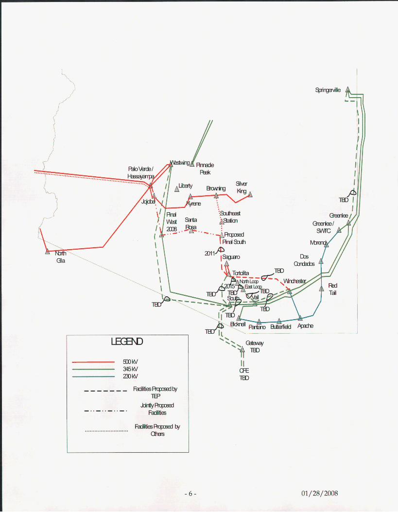
I TEP is a participant in the Pinal West - Pinal South portion of the Pinal West - Southeast
Valley 500 kV project. TEP plans to construct a 500 kV line between the proposed Pinal South
Switchyard and TEP’s Tortolita Substation in the year 2011.
EHV Transmission System
Tucson Electric Power Company (TEP) is a member of the Westconnect Planning Area and the
Southwest Area Transmission Planning Group (SWAT). TEP participates in various SWAT
subcommittees including: SWAT Central Arizona Transmission EHV, SWAT Central Arizona
HV, SWAT Colorado River Transmission, SWAT Arizona-New Mexico, and Southeast
Arizona Transmission System (SATS). Each of these subcommittees has been involved in
studying various generation and transmission projects to enhance and increase utilization of
the existing system. The SATS study includes all or part of Pima, Pinal, Cochise, and Santa
Cruz counties and has the largest direct impact on TEP.
TEP is a participant in the Hassayampa - Pinal West 500 kV project, which will be in service in
2008. TEP’s Westwing - South 345 kV line will loop in at the new Pinal West 500/345 kV
substation.
TEP is evaluating various EHV alternatives for load serving capability within TEP’s service
territory including a possible 345 kV line between TEP’s Tortolita Substation and Vail
Substation with a loop in at the North Loop and East Loop Substations. Other alternatives are
also being considered that will involve additional HV transmission within TEP’s service
territory.
- 3 - 01/28/ 2008
138kV Local Transmission System
TEP performs an annual review of its 138kV system performance over a ten-year
planning horizon. This results in a schedule for new facilities and upgrades to existing
facilities assuring adequate transmission capacity within TEP’s service territory as Tucson
continues to grow. TEP‘s 138kV system is improved to accommodate new 138/13.8kV
substations, increased line loading, and mitigate localized stability issues.
Load projection analysis looks at distribution system needs and identifies the impact of
load growth at each of TEP’s distribution substations. This results in proposed new 138/13.8
kV substations and new 138kV transmission lines. Load projection also provides input to the
power flow analysis used to identify thermal overloads as Tucson continues to grow.
Power flow analysis looks for thermal overloads during normal and contingency operation
based on WECC/NERC Level A, B and C reliability criteria. Contingencies include:
0 Loss of major EHV import
0 Loss of critical local generation
0 Single 138kV circuit outages
0 Credible 138kV multiple circuit outages
Critical circuits initially out of service with system operating acceptably followed by a
subsequent outage.
0
- 4 - 01/28/2008
Thermal overloads are addressed with:
0 New transmission lines
0 Uprating existing lines (increase NESC clearances or larger ampacity wire)
New generation (when more economical than transmission) 0
0 Other cost effective measures
Transmission facilities are also added at 138kV to increase reliability at substations that are
served radially.
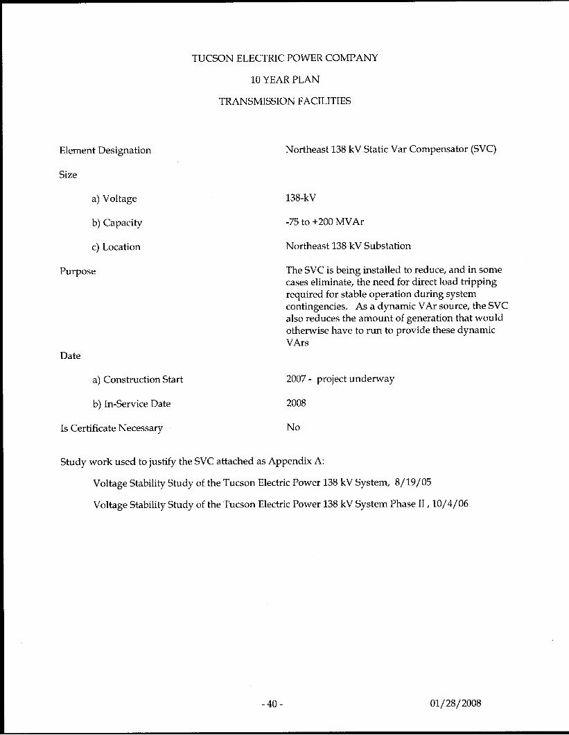
TEP is in the process of installing a -75 to +200 MVAr Static Var Ccompensator at its
Northeast 138 kV substation scheduled to be in-service by the summer of 2008.
- 5 - 01/28/2008
-Rqxsedb/ afias ...........................
01/28/2008
? I S w (Na.hm I
TEP 10 YEAR TRANSMISSION PLAN LOCAL SYSTEM SINGLE LINE t
rf r
01/ 28/ 2008
TUCSON ELECTRIC POWER COMPANY
10 YEAR PLAN
TRANSMISSION FACILITIES
Line Designation
Size
a) Voltage
b) Capacity
c) Point of Origin
d) Point of Termination
e) Length
Routing
Purpose
Date
a) Construction Start
b) In-Service Date
Is Certificate Necessary
Technical Studies
Interconnection of Westwing - South 345 kV with future Hassyampa - Pinal West 500 kV line' via new Pinal West 500/345 kV Substation
345-kV
System dependent
Westwing - South Line
Future Pinal West substation (Sec. 6 T5S R1E)
Less than 1 mile
Adjacent to Westwing - South 345 kV line.
To reinforce TEP's EHV system and to provide a higher capacity link for the flow of power from the Palo Verde area into TEP's service territory.
2007
2008
Case #124
Studies completed via CATS, WATS, and Palo Verde - Southeast Station study groups.
' A joint project being jointly developed with SRP as project manager - 8 - 01/28/2008
~ ~~
TUCSON ELECTRIC POWER COMPANY
10 YEAR PLAN
TRANSMISSION FACILITIES
Line Designation
Size
a) Voltage
b) Capacity
c) Point of Origin
d) Point of Termination
e) Length
Routing
Purpose
Date
a) Construction Start
b) In-Service Date
Is Certificate Necessary
Technical Studies
Pinal South Substation to Tortolita Substation
500-kV
System dependent
Future Pinal South substation
Tortolita Substation (Sec. 14 TlOS RlOE)
Approximately 30 miles
Unknown
To reinforce TEP's EHV system and to provide a higher capacity link for the flow of power from the Palo Verde area into TEP's northern service territory.
2010
2011
Yes
Studies in progress via SWAT and internal TEP study efforts.
- 9 - 01/ 28/2008
TUCSON ELECTRIC POWER COMPANY
10 YEAR PLAN
TRANSMISSION FACILITIES
Line Designation
Size
a) Voltage
b) Capacity
c) Point of Origin
d) Point of Termination
e) Length
Routing
Purpose
Date
a) Construction Start
b) In-Service Date
Is Certificate Necessary
Technical Studies
Tortolita Substation to Vail Substation (through North Loop and East Loop Substations)
345-kV
System dependent
Tortolita Substation (See. 14 TlOS RlOE)
Vail Substation (See. 4 T16S R15E)
Approximately 60 miles
Unknown
To reinforce TEP's EHV system and to provide a new tie between TEP's HV and EHV systems.
2013
Phase 1 - 2014 Tortolita Substation to North Loop Substation
Phase 2 - Under Review East Loop Substation
North Loop Substation to
Phase 3 - Under Review Vail Substation
East Loop Substation to
Yes
Studies in progress via SWAT and internal TEP study efforts.
-10- 01/28/2008
Line Designation
Size
a) Voltage
b) Capacity
c) Point of Origin
d) Point of Termination
e) Length
Routing
Purpose
TUCSON ELECTRIC POWER COMPANY
10 YEAR PLAN
TRANSMISSION FACILITIES
Date
a) Construction Start
b) In-Service Date
Is Certificate Necessary
Technical Studies
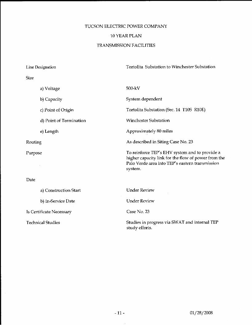
Tortolita Substation to Winchester Substation
500-kV
System dependent
Tortolita Substation (Sec. 14 TlOS RlOE)
Winchester Substation
Approximately 80 miles
As described in Siting Case No. 23
To reinforce TEP's EHV system and to provide a higher capacity link for the flow of power from the Palo Verde area into TEP's eastern transmission system.
Under Review
Under Review
Case No. 23
Studies in progress via SWAT and internal TEP study efforts.
- 11 - 01/28/2008
TUCSON ELECTRIC POWER COMPANY
10 YEAR PLAN
TRANSMISSION FACILITIES
Line Designation
Size
a) Voltage
b) Capacity
c) Point of Origin
d) Point of Termination
e) Length
Routing
Purpose
Date
a) Construction Start
b) In-Service Date
Is Certificate Necessary
Technical Studies
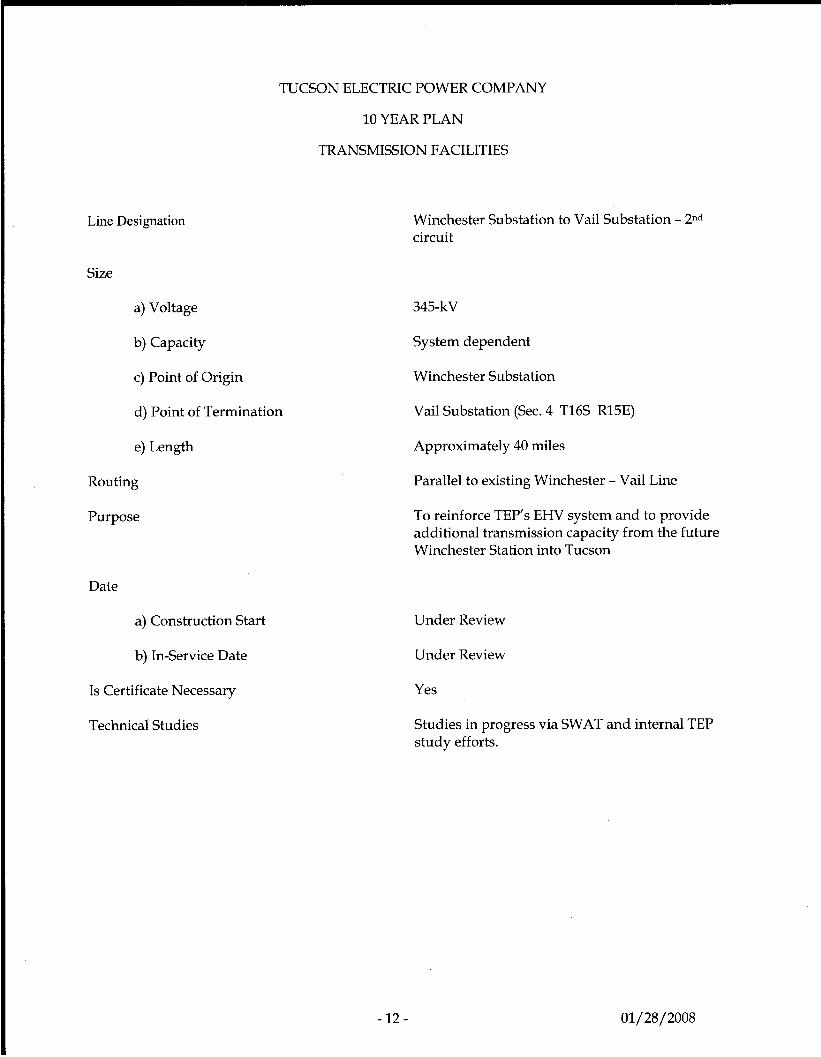
Winchester Substation to Vail Substation - 2nd circuit
345-kV
System dependent
Winchester Substation
Vail Substation (Sec. 4 T16S R15E)
Approximately 40 miles
Parallel to existing Winchester - Vail Line
To reinforce TEP’s EHV system and to provide additional transmission capacity from the future Winchester Station into Tucson
Under Review
Under Review
Yes
Studies in progress via SWAT and internal TEP study efforts.
- 12 - 01/ 28/ 2008
Line Designation
Size
a) Voltage
b) Capacity
c) Point of Origin
d) Point of Termination
e) Length
Routing
Purpose
TUCSON ELECTRIC POWER COMPANY
10 YEAR PLAN
TRANSMISSION FACILITIES
Date
a) Construction Start
b) In-Service Date
Is Certificate Necessary
Technical Studies
-13-
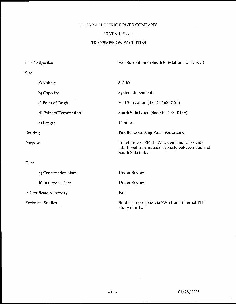
Vail Substation to South Substation - 2nd circuit
345-kV
System dependent
Vail Substation (Sec. 4 T16S R15E)
South Substation (Sec. 36 T16S R13E)
14 miles
Parallel to existing Vail - South Line
To reinforce TEP’s EHV system and to provide additional transmission capacity between Vail and South Substations
Under Review
Under Review
No
Studies in progress via SWAT and internal TEP study efforts.
01/ 28/ 2008
Line Designation
Size
a) Voltage
b) Capacity
c) Point of Origin
d) Point of Termination
e) Length
TUCSON ELECTRIC POWER COMPANY
10 YEAR PLAN
TRANSMISSION FACILITIES
Routing
Purpose
Date
a) Construction Start
b) In-Service Date
Is Certificate Necessary
Technical Studies
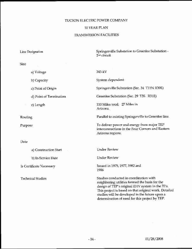
Springerville Substation to Greenlee Substation - 2nd circuit
345-kV
System dependent
Springerville Substation (Sec. 34 Tl lN R30E)
Greenlee Substation (Sec. 29 T5S R31E)
110 Miles total; 27 Miles in Arizona.
Parallel to existing Springerville to Greenlee line.
To deliver power and energy from major TEP interconnections in the Four Corners and Eastern Arizona regions.
Under Review
Under Review
Issued in 1975,1977,1982 and 1986
Studies conducted in coordination with neighboring utilities formed the basis for the design of TEP's original EHV system in the 70's. This project is based on that original work. Detailed studies will be developed in the future upon a determination of need for this project by TEP.
- 14 - 01/ 28/ 2008
TUCSON ELECTRIC POWER COMPANY
Line Designation
Size
a) Voltage
b) Capacity
c) Point of Origin
d) Point of Termination
e) Length
Routing
Purpose
Date
a) Construction Start
b) In-Service Date
Is Certificate Necessary
Technical Studies
10 YEAR PLAN
TRANSMISSION FACILITIES
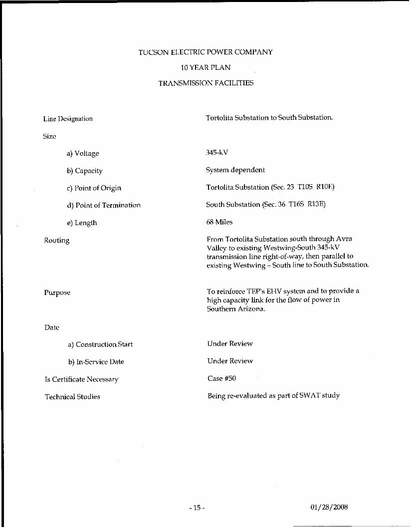
Tortolita Substation to South Substation.
345-kV
System dependent
Tortolita Substation (Sec. 23 TlOS RlOE)
South Substation (Sec. 36 T16S R13E)
68 Miles
From Tortolita Substation south through Avra Valley to existing Westwing-South 345-kV transmission line right-of-way, then parallel to existing Westwing - South line to South Substation.
To reinforce TEP's EHV system and to provide a high capacity link for the flow of power in Southern Arizona.
Under Review
Under Review
Case #50
Being re-evalua.2d as pal - of SWAT study
- 15 - 01/ 28/ 2008
Line Designation
Size
a) Voltage
b) Capacity
c) Point of Origin
d) Point of Termination
e) Length
Routing
Purpose
TUCSON ELECTRIC POWER COMPANY
10 YEAR PLAN
TRANSMISSION FACILITIES
Date
a) Construction Start
b) In-Service Date
Is Certificate Necessary
Technical Studies
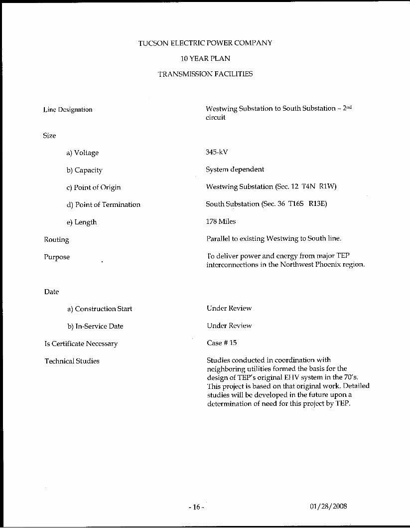
Westwing Substation to South Substation - 2nd circuit
345-kV
System dependent
Westwing Substation (Sec. 12 T4N R1W)
South Substation (Sec. 36 T16S R13E)
178 Miles
Parallel to existing Westwing to South line.
To deliver power and energy from major TEP interconnections in the Northwest Phoenix region.
Under Review
Under Review
Case # 15
Studies conducted in coordination with neighboring utilities formed the basis for the design of TEP’s original EHV system in the 70’s. This project is based on that original work. Detailed studies will be developed in the future upon a determination of need for this project by TEP.
- 1 6 - 01/ 28/2008
Line Designation
Size
a) Voltage
b) Capacity
c) Point of Origin
d) Points of Termination
e) Length
Routing
TUCSON ELECTRIC POWER COMPANY
I O YEAR PLAN
TRANSMISSION FACILITIES
Purpose
Date
a) Construction Start
b) In-Service Date
Is Certificate Necessary
Technical Studies
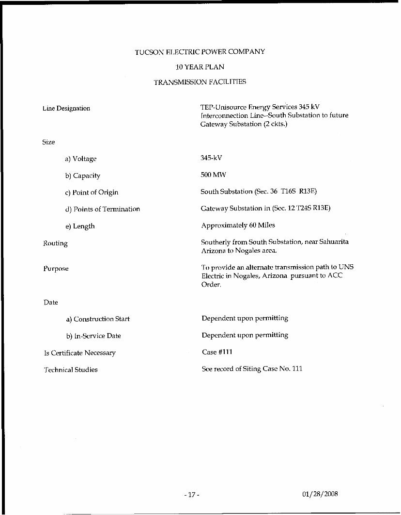
TEP-Unisource Energy Services 345 kV Interconnection Line--South Substation to future Gateway Substation (2 ckts.)
345-kV
500 MW
South Substation (Sec. 36 T16S R13E)
Gateway Substation in (Sec. 12 T24S R13E)
Approximately 60 Miles
Southerly from South Substation, near Sahuarita Arizona to Nogales area.
To provide an alternate transmission path to UNS Electric in Nogales, Arizona pursuant to ACC Order.
Dependent upon permitting
Dependent upon permitting
Case #111
See record of Siting Case No. 111
-17- 01/28/2008
Line Designation
Size
a) Voltage
b) Capacity
c) Point of Origin
d) Points of Termination
TUCSON ELECTRIC POWER COMPANY
10 YEAR PLAN
TRANSMISSION FACILITIES
e) Length
Routing
Purpose
Date
a) Construction Start
b) In-Service Date
Is Certificate Necessary
Technical Studies
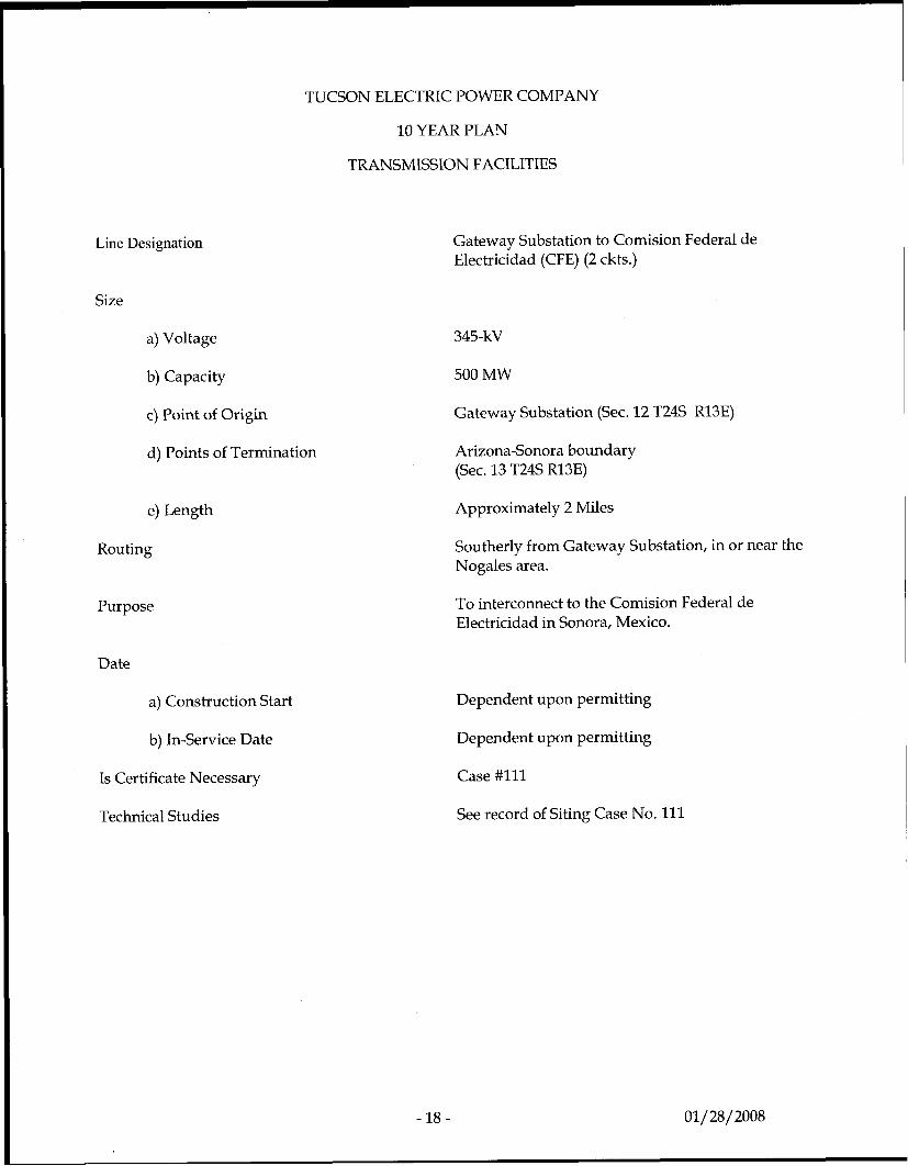
Gateway Substation to Comision Federal de Electricidad (CFE) (2 ckts.)
345-kV
500 MW
Gateway Substation (Sec. 12 T24S R13E)
Arizona-Sonora boundary (Sec. 13 T24S R13E)
Approximately 2 Miles
Southerly from Gateway Substation, in or near the Nogales area.
To interconnect to the Comision Federal de Electricidad in Sonora, Mexico.
Dependent upon permitting
Dependent upon permitting
Case #111
See record of Siting Case No. 111
-18- 01/ 28/ 2008
Line Designation
Size
a) Voltage
b) Capacity
c) Point of Origin
d) Point of Termination
e) Length
Routing
Purpose
TUCSON ELECTRIC POWER COMPANY
10 YEAR PLAN
TRANSMISSION FACILITIES
Date
a) Construction Start
b) In-Service Date
Is Certificate Necessary
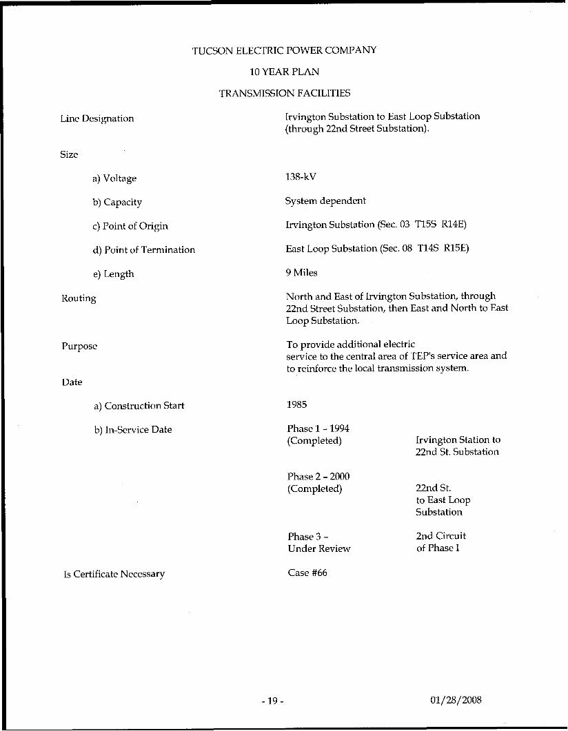
Irvington Substation to East Loop Substation (through 22nd Street Substation).
138-kV
System dependent
Irvington Substation (Sec. 03 T15S R14E)
East Loop Substation (Sec. 08 T14S R15E)
9 Miles
North and East of Irvington Substation, through 22nd Street Substation, then East and North to East Loop Substation.
To provide additional electric service to the central area of TEP's service area and to reinforce the local transmission system.
1985
Phase 1 - 1994 (Completed)
Phase 2 - 2000 (Completed)
Phase 3 - Under Review
Case #66
Irvington Station to 22nd St. Substation
22nd St. to East Loop Substation
2nd Circuit of Phase I
-19- 01/28/2008
TUCSON ELECTRIC POWER COMPANY
10 YEAR PLAN
TRANSMISSION FACILITIES
Line Designation
Size a) Voltage
b) Capacity
c) Point of Origin
d) Point of Termination
e) Length
Routing
Purpose
Date a) Construction Start
b) In-Service Date
Is Certificate Necessary
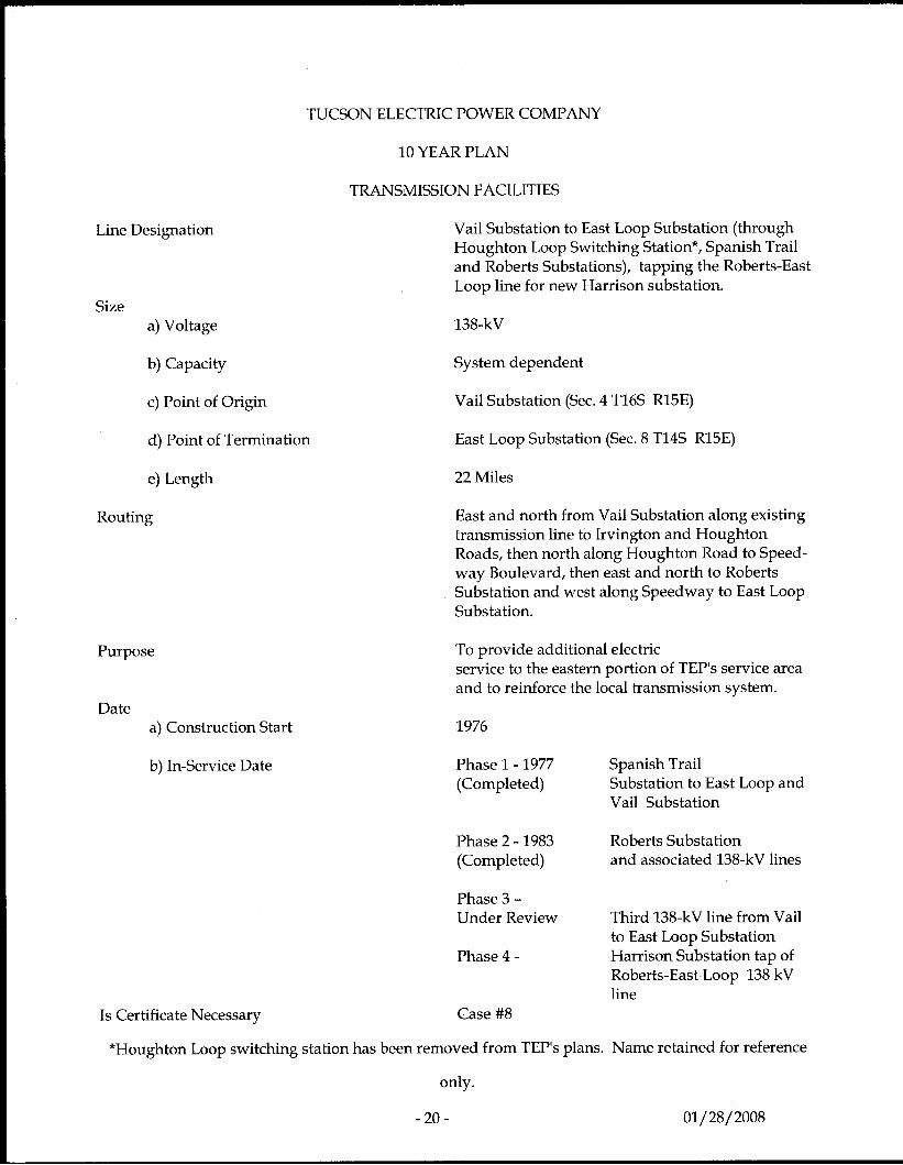
Vail Substation to East Loop Substation (through Houghton Loop Switching Station*, Spanish Trail and Roberts Substations), tapping the Roberts-East Loop line for new Harrison substation.
138-kV
System dependent
Vail Substation (Sec. 4 T16S R15E)
East Loop Substation (Sec. 8 T14S R15E)
22 Miles
East and north from Vail Substation along existing transmission line to Irvington and Houghton Roads, then north along Houghton Road to Speed- way Boulevard, then east and north to Roberts Substation and west along Speedway to East Loop Substation.
To provide additional electric service to the eastern portion of TEP's service area and to reinforce the local transmission system.
1976
Phase 1 - 1977 (Completed)
Spanish Trail Substation to East Loop and Vail Substation
Phase 2 - 1983 (Completed) and associated 138-kV lines
Roberts Substation
Phase 3 - Under Review
Phase 4 -
Third 138-kV line from Vail to East Loop Substation Harrison Substation tap of Roberts-East Loop 138 kV line
Case #8
*Houghton Loop switching station has been removed from TEP's plans. Name retained for reference
only.
- 20 - 01/28/ 2008
Line Designation
Size
a) Voltage
b) Capacity
c) Point of Origin
d) Point of Termination
e) Length
Routing
TUCSON ELECTRIC POWER COMPANY
10 YEAR PLAN
TRANSMISSION FACILITIES
Purpose
Date
a) Construction Start
b) In-Service Date
Is Certificate Necessary a9
- 21 -
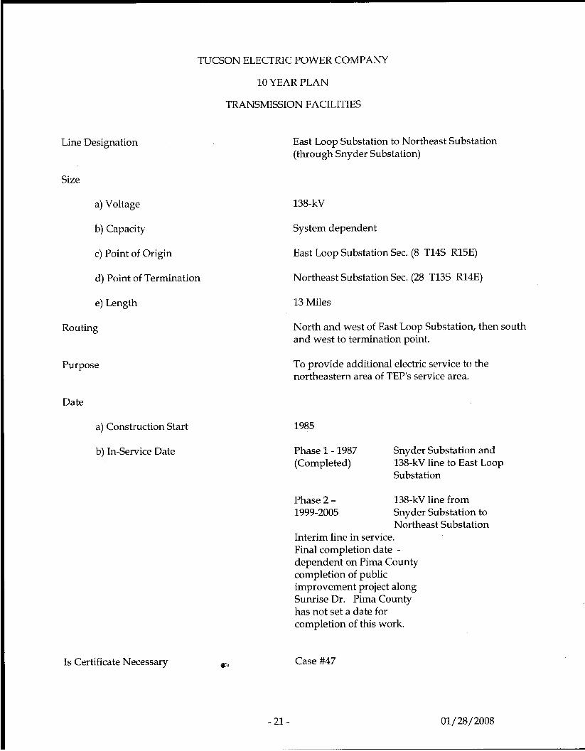
East Loop Substation to Northeast Substation (through Snyder Substation)
138-kV
System dependent
East Loop Substation Sec. (8 T14S R15E)
Northeast Substation Sec. (28 T13S R14E)
13 Miles
North and west of East Loop Substation, then south and west to termination point.
To provide additional electric service to the northeastern area of TEP's service area.
1985
Phase 1 - 1987 (Completed)
Snyder Substation and 138-kV line to East Loop Substation
Phase 2 - 138-kV line from 1999-2005 Snyder Substation to
Northeast Substation Interim line in service. Final completion date - dependent on Pima County completion of public improvement project along Sunrise Dr. Pima County has not set a date for completion of this work.
Case #47
01/28/2008
TUCSON ELECTRIC POWER COMPANY
10 YEAR PLAN
TRANSMISSION FACILITIES
Line Designation
Size
a) Voltage
b) Capacity
c) Point of Origin
d) Point of Termination
e) Length
Routing
Purpose
Date
a) Construction Start
b) In-Service Date
Is Certificate Necessary
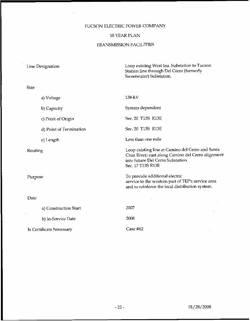
Loop existing West Ina Substation to Tucson Station line through Del Cerro (formerly Sweetwater) Substation.
138-kV
System dependent
Sec.20 T13S R13E
Sec.20 T13S R13E
Less than one mile
Loop existing line at Camino del Cerro and Santa Cruz River; east along Camino del Cerro alignment into future Del Cerro Substation. Sec. 17 T13S R13E
To provide additional electric service to the western part of TEP's service area and to reinforce the local distribution system.
2007
2008
Case #62
- 22 - 01/28/2008
TUCSON ELECTRIC POWER COMPANY
10 YEAR PLAN
Line Designation
Size
a) Voltage
b) Capacity
c) Point of Origin
d) Point of Termination
e) Length
Routing
Purpose
Date
a) Construction Start
b) In-Service Date
Is Certificate Necessary
TRANSMISSION FACILITIES
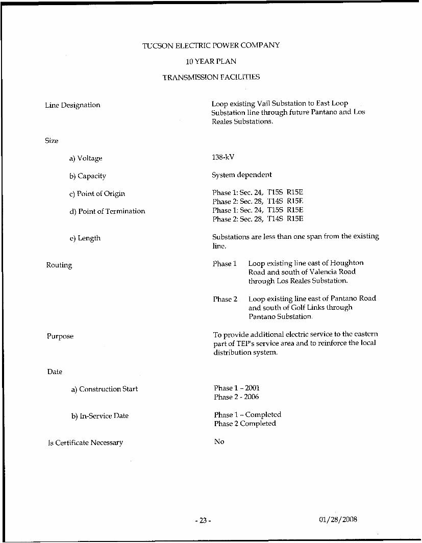
Loop existing Vail Substation to East Loop Substation line through future Pantano and Los Reales Substations.
138-kV
System dependent
Phase 1: Sec. 24, T15S R15E Phase 2: Sec. 28, T14S R15E Phase 1: Sec. 24, T15S R15E Phase 2: Sec. 28, T14S R15E
Substations are less than one span from the existing line.
Phase 1 Loop existing line east of Houghton Road and south of Valencia Road through Los Reales Substation.
Phase 2 Loop existing line east of Pantano Road and south of Golf Links through Pantano Substation.
To provide additional electric service to the eastern part of TEP's service area and to reinforce the local distribution system.
Phase 1 - 2001 Phase 2 - 2006
Phase 1 - Completed Phase 2 Completed
No
TUCSON ELECTRIC POWER COMPANY
10 YEAR PLAN
TRANSMISSION FACILITIES
Line Designation
Size
a) Voltage
b) Capacity
c) Point of Origin
d) Point of Termination
e) Length
Routing
Purpose
Date
a) Construction Start
b) In-Service Date
Is Certificate Necessary
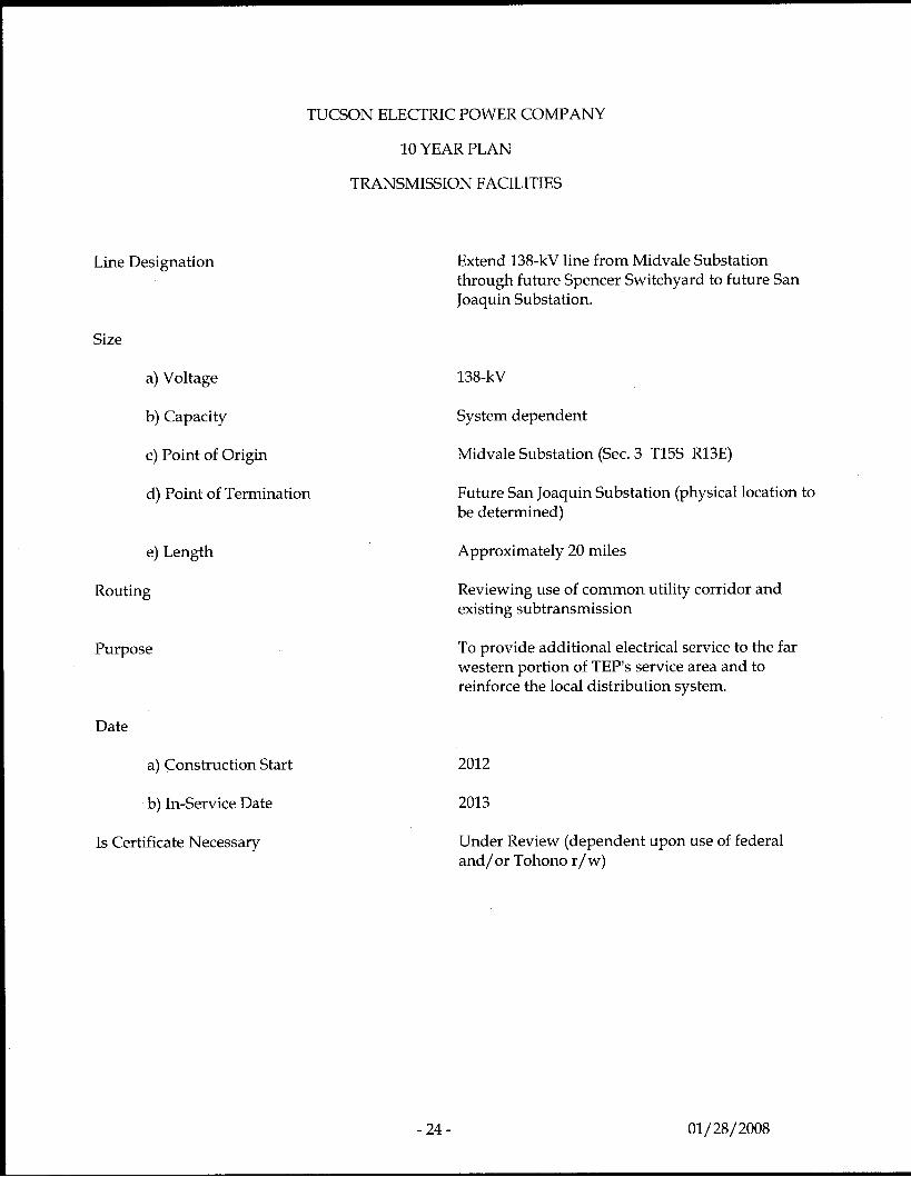
Extend 138-kV line from Midvale Substation through future Spencer Switchyard to future San Joaquin Substation.
138-kV
System dependent
Midvale Substation (Sec. 3 T15S R13E)
Future San Joaquin Substation (physical location to be determined)
Approximately 20 miles
Reviewing use of common utility corridor and existing subtransmission
To provide additional electrical service to the far western portion of TEP's service area and to reinforce the local distribution system.
2012
2013
Under Review (dependent upon use of federal and/or Tohono r/w)
- 24 - 01/28/2008
TUCSON ELECTRIC POWER COMPANY
10 YEAR PLAN
TRANSMISSION FACILITIES
Line Designation
Size
a) Voltage
b) Capacity
c) Point of Origin
d) Point of Termination
e) Length
Routing
Purpose
Date
a) Construction Start
b) In-Service Date
Is Certificate Necessary
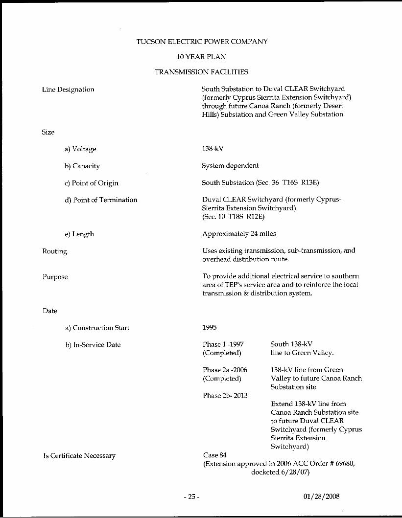
South Substation to Duval CLEAR Switchyard (formerly Cyprus Sierrita Extension Switchyard) through future Canoa Ranch (formerly Desert Hills) Substation and Green Valley Substation
138-kV
System dependent
South Substation (Sec. 36 T16S R13E)
Duval CLEAR Switchyard (formerly Cyprus- Sierrita Extension Switchyard) (Sec. 10 T18S R12E)
Approximately 24 miles
Uses existing transmission, sub-transmission, and overhead distribution route.
To provide additional electrical service to southern area of TEP's service area and to reinforce the local transmission & distribution system.
1995
Phase 1 -1997 South 138-kV (Completed) line to Green Valley.
Phase 2a -2006 (Completed)
Phase 2b- 2013
138-kV line from Green Valley to future Canoa Ranch Substation site
Extend 138-kV line from Canoa Ranch Substation site to future Duval CLEAR Switchyard (formerly Cyprus Sierrita Extension Switchyard)
Case 84 (Extension approved in 2006 ACC Order # 69680,
docketed 6/28/07)
- 25 - 01/28/2008
Line Designation
Size
a) Voltage
b) Capacity
c) Point of Origin
d) Point of Termination
e) Length
Routing
TUCSON ELECTRIC POWER COMPANY
10 YEAR PLAN
TRANSMISSION FACILITIES
Purpose
Date
a) Construction Start
b) In-Service Date
Is Certificate Necessary
- 26 -
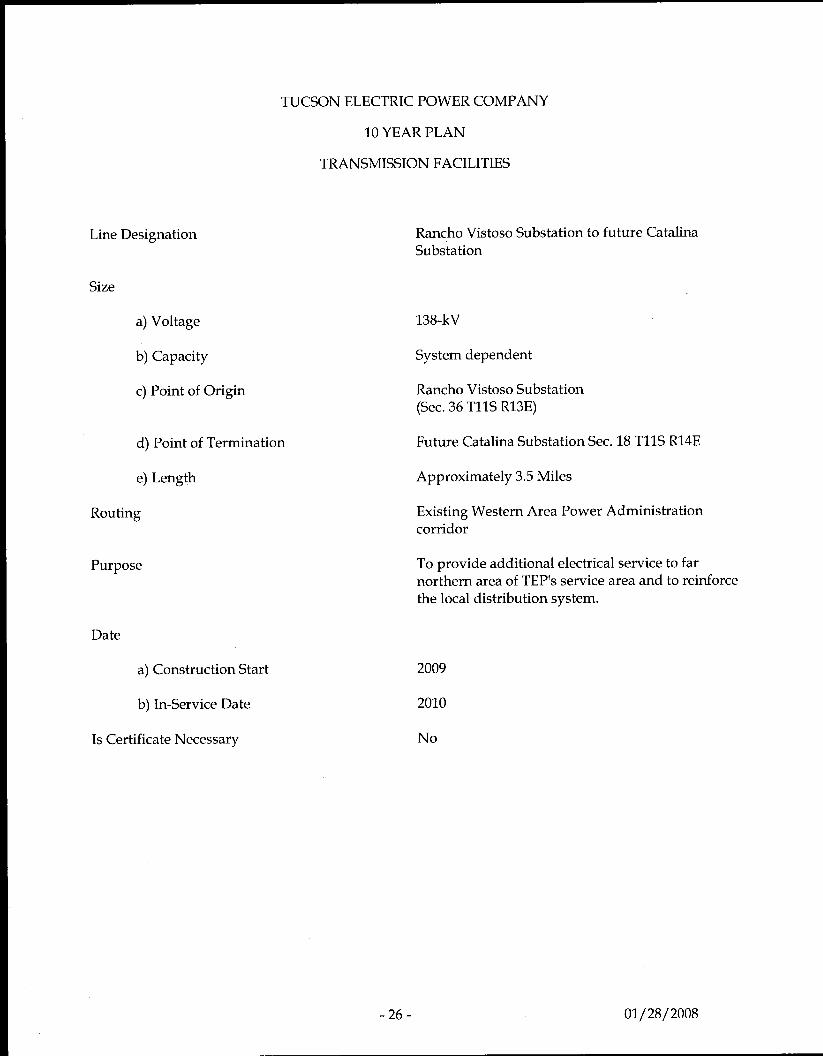
Rancho Vistoso Substation to future Catalina Substation
138-kV
System dependent
Rancho Vistoso Substation (Sec. 36 TllS R13E)
Future Catalina Substation Sec. 18 TllS R14E
Approximately 3.5 Miles
Existing Western Area Power Administration corridor
To provide additional electrical service to far northern area of TEP's service area and to reinforce the local distribution system.
2009
2010
No
01/28/2008
Line Designation
Size
a) Voltage
b) Capacity
c) Point of Origin
d) Point of Termination
TUCSON ELECTRIC POWER COMPANY
10 YEAR PLAN
TRANSMISSION FACILITIES
e) Length
Routing
Purpose
Date
a) Construction Start
b) In-Service Date
Is Certificate Necessary
-27-
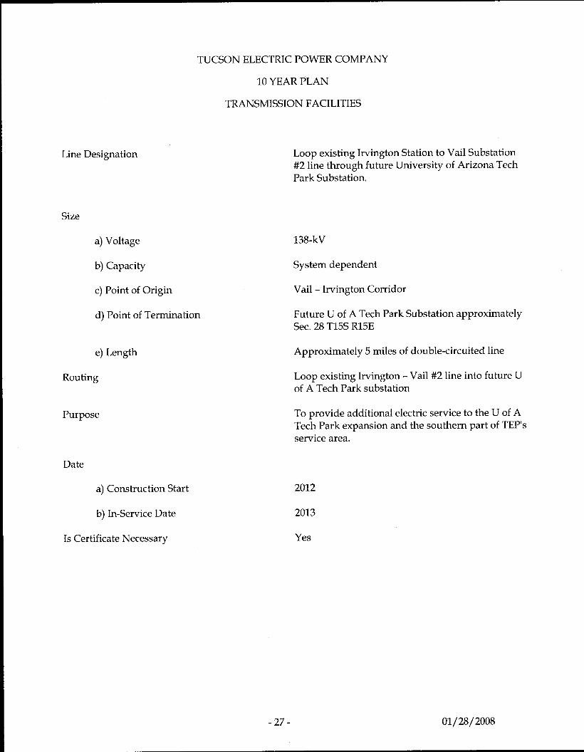
Loop existing Irvington Station to Vail Substation #2 line through future University of Arizona Tech Park Substation.
138-kV
System dependent
Vail - Irvington Corridor
Future U of A Tech Park Substation approximately Sec. 28 T15S R15E
Approximately 5 miles of double-circuited line
Loop existing Irvington - Vail#2 line into future U of A Tech Park substation
To provide additional electric service to the U of A Tech Park expansion and the southern part of TEP's service area.
2012
2013
Yes
01/28/2008
Line Designation
Size
a) Voltage
b) Capacity
c) Point of Origin
d) Point of Termination
e) Length
Routing
Purpose
TUCSON ELECTRIC POWER COMPANY
10 YEAR PLAN
TRANSMISSION FACILITIES
Date
a) Construction Start
b) In-Service Date
Is Certificate Necessary
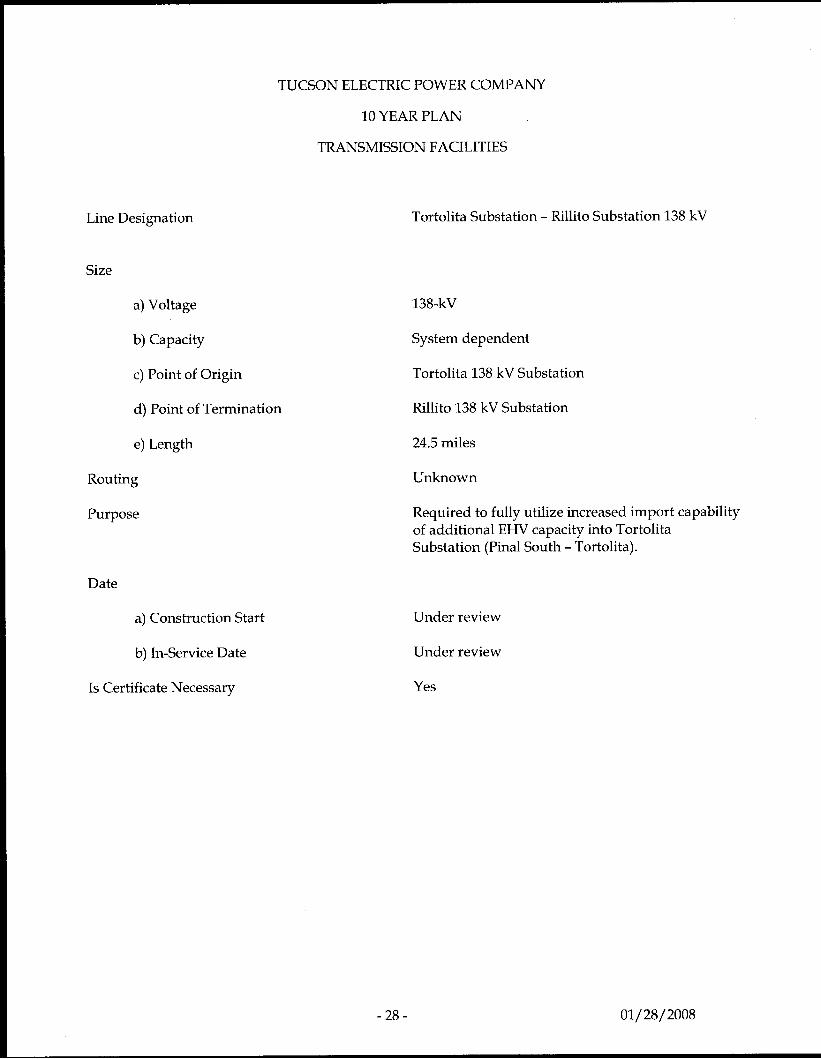
Tortolita Substation - Rillito Substation 138 kV
138-kV
System dependent
Tortolita 138 kV Substation
Rillito 138 kV Substation
24.5 miles
Unknown
Required to fully utilize increased import capability of additional EHV capacity into Tortolita Substation (Pinal South - Tortolita).
Under review
Under review
Yes
- 28 - 01/ 28/ 2008
Line Designation
TUCSON ELECTRIC POWER COMPANY
10 YEAR PLAN
TRANSMISSION FACILITIES
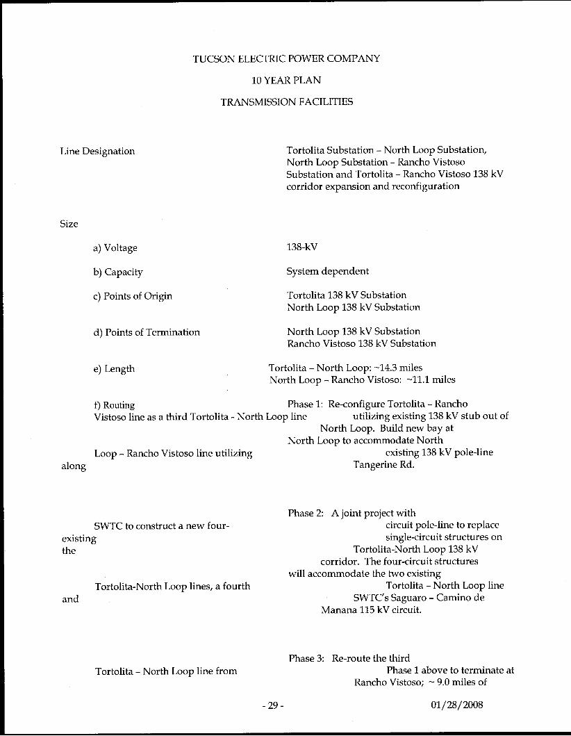
Tortolita Substation - North Loop Substation, North Loop Substation - Rancho Vistoso Substation and Tortolita - Rancho Vistoso 138 kV corridor expansion and reconfiguration
Size
a) Voltage 138-kV
b) Capacity System dependent
c) Points of Origin
d) Points of Termination
e) Length
Tortolita 138 kV Substation North Loop 138 kV Substation
North Loop 138 kV Substation Rancho Vistoso 138 kV Substation
Tortolita - North Loop: -14.3 miles North Loop - Rancho Vistoso: -11.1 miles
f) Routing Vistoso line as a third Tortolita - North Loop line
Phase 1: Re-configure Tortolita - Rancho utilizing existing 138 kV stub out of
North Loop. Build new bay at North Loop to accommodate North
Loop - Rancho Vistoso line utilizing existing 138 kV pole-line along Tangerine Rd.
SWTC to construct a new four- existing the
Tortolita-North Loop lines, a fourth and
Tortolita - North Loop line from
Phase 2 A joint project with circuit pole-line to replace single-circuit structures on
Tortolita-North Loop 138 kV corridor. The four-circuit structures
will accommodate the two existing Tortolita - North Loop line
SWTC’s Saguaro - Camino de Manana 115 kV circuit.
Phase 3: Re-route the third Phase 1 above to terminate at
Rancho Vistoso; - 9.0 miles of
- 29 - 01/28/2008
Rancho Vistoso; - 9.0 miles of
will be uprated to 138 kV. Tap the existing 46 kV sub-transmission
North Loop - Rancho Vistoso line to supply the
along Tangerine Rd.
new Naranja 138/13.8 kV substation
Purpose
Date
f ) Construction Start
g) In-Service Date
Is Certificate Necessary
Required for NERC N-1 issues on these parallel path circuits.
2008
Phasel: 2008
Phase2: 2009
Phase3: 2010
Phasel: Yes Phase 2: Yes
-30- 01/28/2008
Line Designation
Size a) Voltage
b) Capacity
c) Point of Origin
d) Point of Termination
e) Length
TUCSON ELECTRIC POWER COMPANY
10 YEAR PLAN
TRANSMISSION FACILITIES
Routing
Purpose
Date
Vail Substation - SS NO27 Substation- Cienega Substation - SS NO20 Substation- Spanish Trail Substation 138 kV
138-kV
System dependent
Vaill38 kV Substation
Spanish Trail 138 kV Substation
Phase 1: Vail - Cienega Phase 2: Vail - SSN027 Phase 3: Cienega - SS NO20 -14.0 miles
-12.2miles -5.3 miles
Phase 1: Utilize the existing Vail-Fort Huachuca/ Vail- Spanish Trail 138 kV corridor between Vail Substation and seven spans east of Wentworth Rd., then new double-circuit 138 kV northeast -2.0 miles to proposed Cienega site in T16S R16E Sec 16.
Phase 2: Tap the Vail - Cienega 138 kV line from Phase 1 and extend new double-circuit 138kV - 2.0 miles south along Houghton Rd. to proposed SS NO27 substation site.
Phase 3: Tap the Cienega - Spanish Trail line from Phase 1 and new circuit out of Los Reales extended via new triple- circuit 138kV east of Los Reales - 3.0 miles east along Los Reales Rd to proposed SS NO20 substation site - 0.75 miles east of E. Old Spanish Trail.
Required to serve load at the new Cienega 138/13.8 kV Substation located approximately 7.5 miles east-southeast of the Vail Substation, and the future SS NO27 and SS NO20 138/13.8 kV Substations located approximately 4.0 miles southwest and 6.0 miles north of the Cienega Substation, respectively.
Phase 1: Cienega a) Construction Start 2008 b) In-Service Date 2010
Phase 2: SS NO27 a) Construction Start 2018 b) In-Service Date 2020
- 31 - 01/ 28/ 2008
Is Certificate Necessary
Phase 3: SS NO20 a) Construction Start 2021 b) In-Service Date 2023
Yes
- 32 - 01/ 28/ 2008
Line Designation
Size
a) Voltage
b) Capacity
c) Point of Origin
d) Point of Termination
Date
TUCSON ELECTRIC POWER COMPANY
10 YEAR PLAN
TRANSMISSION FACILITIES
e) Length
Routing
Purpose
a) Construction Start
b) In-Service Date
Is Certificate Necessary
New Cienega Substation - Mountain View Substation 138 kV Circuit and Vail Substation - Fort Huachuca Tap for Mountain View Substation
138-kV
System dependent
Cienega 138 kV Substation (T16S R16E Sec 16)
Mountain View 138 kV Substation (T17S R16E Sec 2)
4.7 miles
Extend 138 kV pole-line out of the Cienega substation east along Dawn Dr. to the Southern Pacific Railroad, then southeast along railroad, then south to the Mountain View Substation site.
In addition the Mountain View substation will tap the existing Vail Substation - Ft. Huachuca Substation line to increase reliability to Mountain View with a modest improvement in voltage regulation to Ft. Huachuca.
Required to serve load at the new Mountain View 138/13.8 kV Substation approximately 11 miles south-southeast of the Vail Substation
TBD
TBD
Yes
- 33 - 01/28/2008
Line Designation
Size
a) Voltage
b) Capacity
c) Point of Origin
d) Point of Termination
e) Length
Routing
TUCSON ELECTRIC POWER COMPANY
10 YEAR PLAN
TRANSMISSION FACILITIES
Purpose
Date
a) Construction Start
b) In-Service Date
Is Certificate Necessary
Northeast - Snyder 138 kV - tap for Craycroft- Barril substation
138-kV
System dependent
Northeast 138 kV Substation
Snyder 138 kV Substation
8.0 miles
Existing Northeast-Snyder Corridor requires 1 span of wire to drop into station.
Required to serve load at the new Craycroft-Barril 138/13.8 kV Substation locate approximately 2.75 miles northeast of the Northeast Substation
2010
2011
No
-34- 01/28/2008
Line Designation
Size
a) Voltage
b) Capacity
c) Point of Origin
d) Point of Termination
e) Length
Routing
TUCSON ELECTRIC POWER COMPANY
10 YEAR PLAN
TRANSMISSION FACILITIES
Purpose
Date
a) Construction Start
b) In-Service Date
Is Certificate Necessary
- 35 -
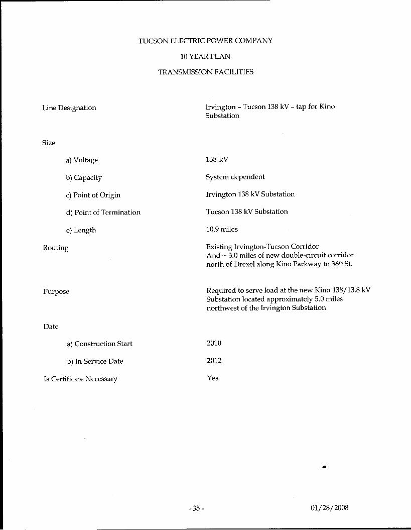
Irvington - Tucson 138 kV - tap for Kino Substation
138-kV
System dependent
Irvington 138 kV Substation
Tucson 138 kV Substation
10.9 miles
Existing Irvington-Tucson Corridor And - 3.0 miles of new double-circuit corridor north of Drexel along Kino Parkway to 36th St.
Required to serve load at the new Kino 138/13.8 kV Substation located approximately 5.0 miles northwest of the Irvington Substation
2010
2012
Yes
",
01/ 28/ 2008
TUCSON ELECTRIC POWER COMPANY
10 YEAR PLAN
TRANSMISSION FACILITIES
Line Designation
Size
a) Voltage
b) Capacity
c) Point of Origin
d) Point of Termination
e) Length
Routing
Purpose
Date Marana (Phase 1)
SS NO1 (Phase 2)
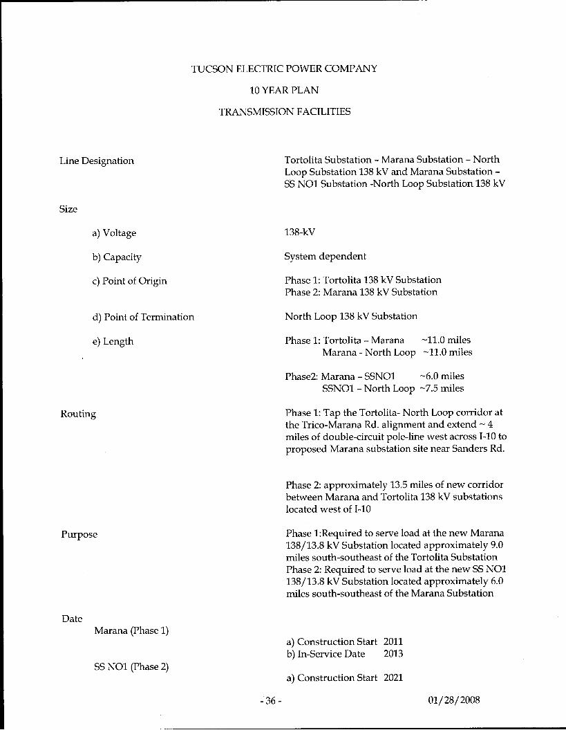
Tortolita Substation - Marana Substation - North Loop Substation 138 kV and Marana Substation - SS NO1 Substation -North Loop Substation 138 kV
138-kV
System dependent
Phase 1: Tortolita 138 kV Substation Phase 2: Marana 138 kV Substation
North Loop 138 kV Substation
Phase 1: Tortolita - Marana -11.0 miles Marana - North Loop -11.0 miles
Phase2: Marana - SSNOl -6.0 miles SSNOl - North Loop -7.5 miles
Phase 1: Tap the Tortolita- North Loop corridor at the Trico-Marana Rd. alignment and extend - 4 miles of double-circuit pole-line west across 1-10 to proposed Marana substation site near Sanders Rd.
Phase 2: approximately 13.5 miles of new corridor between Marana and Tortolita 138 kV substations located west of 1-10
Phase 1:Required to serve load at the new Marana 138/13.8 kV Substation located approximately 9.0 miles south-southeast of the Tortolita Substation Phase 2: Required to serve load at the new SS NO1 138/13.8 kV Substation located approximately 6.0 miles south-southeast of the Marana Substation
a) Construction Start 2011 b) In-Service Date 2013
a) Construction Start 2021
-36- 01/28/2008
Is Certificate Necessary
b) In-Service Date 2023
Yes
-37- 01/ 28/ 2008
TUCSON ELECTRIC POWER COMPANY
10 YEAR PLAN
TRANSMISSION FACILITIES
Line Designation
Size
a) Voltage
b) Capacity
c) Point of Origin
d) Point of Termination
e) Length
Routing
Purpose
Date
a) Construction Start
b) In-Service Date
Is Certificate Necessary
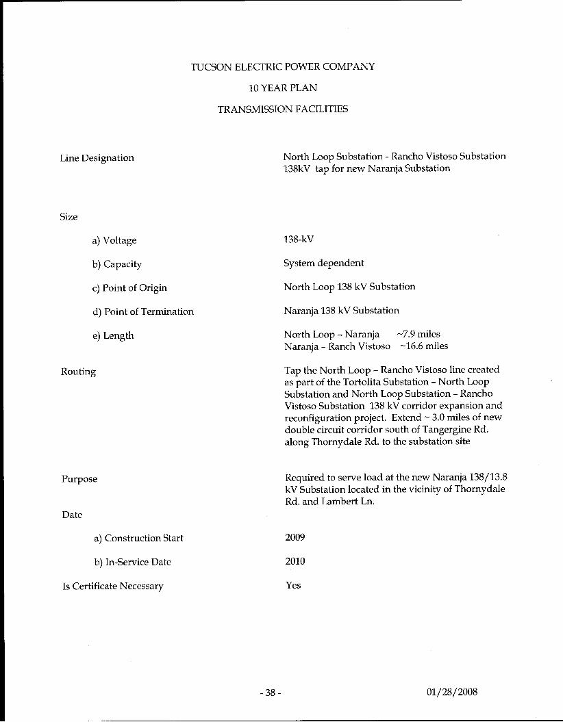
North Loop Substation - Rancho Vistoso Substation 138kV tap for new Naranja Substation
138-kV
System dependent
North Loop 138 kV Substation
Naranja 138 kV Substation
North Loop - Naranja Naranja - Ranch Vistoso
-7.9 miles -16.6 miles
Tap the North Loop - Rancho Vistoso line created as part of the Tortolita Substation - North Loop Substation and North Loop Substation - Rancho Vistoso Substation 138 kV corridor expansion and reconfiguration project. Extend - 3.0 miles of new double circuit corridor south of Tangergine Rd. along Thornydale Rd. to the substation site
Required to serve load at the new Naranja 138/13.8 kV Substation located in the vicinity of Thornydale Rd. and Lambert Ln.
2009
2010
Yes
- 38 - 01/28/2008
Line Designation
Size
a) Voltage
b) Capacity
c) Point of Origin
d) Point of Termination
e) Length
Routing
Purpose
TUCSON ELECTRIC POWER COMPANY
10 YEAR PLAN
TRANSMISSION FACILITIES
Date
a) Construction Start
b) In-Service Date
Is Certificate Necessary
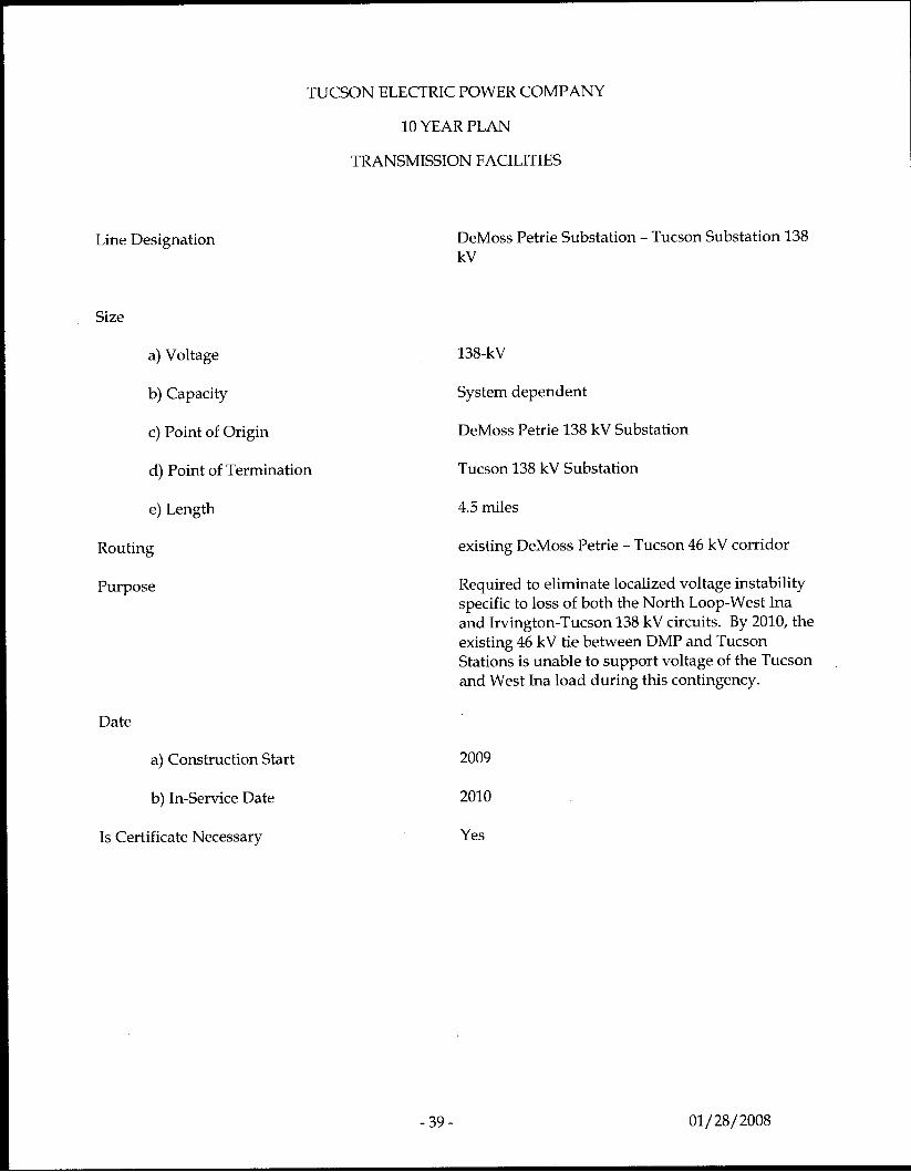
DeMoss Petrie Substation - Tucson Substation 138 kV
138-kV
System dependent
DeMoss Petrie 138 kV Substation
Tucson 138 kV Substation
4.5 miles
existing DeMoss Petrie - Tucson 46 kV corridor
Required to eliminate localized voltage instability specific to loss of both the North Loop-West Ina and Irvington-Tucson 138 kV circuits. By 2010, the existing 46 kV tie between DMP and Tucson Stations is unable to support voltage of the Tucson and West Ina load during this contingency.
2009
2010
Yes
- 39 - 01/ 28/2008
Element Designation
Size
a) Voltage
b) Capacity
c) Location
Purpose
TUCSON ELECTRIC POWER COMPANY
10 YEAR PLAN
TRANSMISSION FACILITIES
Northeast 138 kV Static Var Compensator (SVC)
138-kV
-75 to +200 MVAr
Northeast 138 kV Substation
The SVC is being installed to reduce, and in some cases eliminate, the need for direct load tripping required for stable operation during system contingencies. As a dynamic VAr source, the SVC also reduces the amount of generation that would otherwise have to run to provide these dynamic VArs
Date
a) Construction Start 2007 - project underway
b) In-Service Date 2008
Is Certificate Necessary No
Study work used to justify the SVC attached as Appendix A:
Voltage Stability Study of the Tucson Electric Power 138 kV System, 8/19/05
Voltage Stability Study of the Tucson Electric Power 138 kV System Phase II,10/4/06
-40- 01/28/2008
Line Designation
Size
a) Voltage
b) Capacity
c) Point of Origin
d) Point of Termination
e) Length
TUCSON ELECTRIC POWER COMPANY
10 YEAR PLAN
TRANSMISSION FACILITIES
Routing
Purpose
Date
a) Construction Start
b) In-Service Date
Is Certificate Necessary
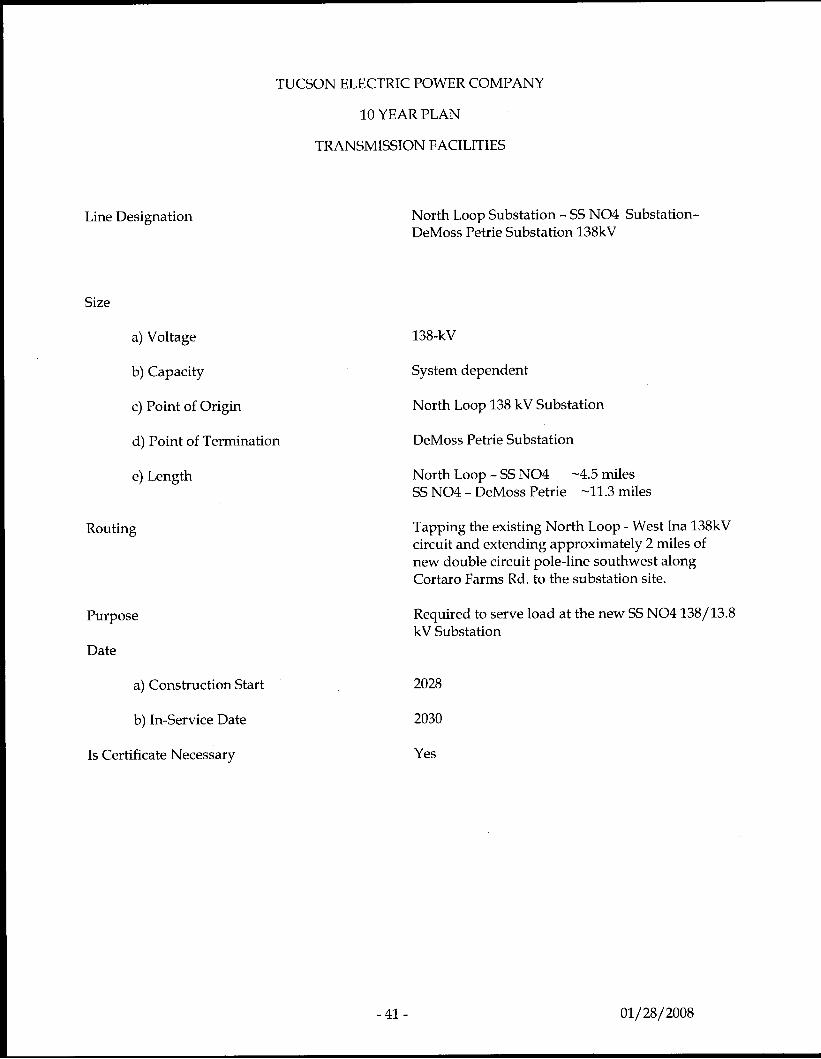
North Loop Substation - SS NO4 Substation- DeMoss Petrie Substation 138kV
138-kV
System dependent
North Loop 138 kV Substation
DeMoss Petrie Substation
North Loop - SS NO4 SS NO4 - DeMoss Petrie
-4.5 miles -11.3 miles
Tapping the existing North Loop - West Ina 138kV circuit and extending approximately 2 miles of new double circuit pole-line southwest along Cortaro Farms Rd. to the substation site.
Required to serve load at the new SS NO4 138/13.8 kV Substation
2028
2030
Yes
-41 - 01/ 28/ 2008
TUCSON ELECTRIC POWER COMPANY
10 YEAR PLAN
TRANSMISSION FACILITIES
Line Designation
Size
a) Voltage
b) Capacity
c) Point of Origin
d) Point of Termination
e) Length
Routing
Purpose
Date
a) Construction Start
b) In-Service Date
Is Certificate Necessary
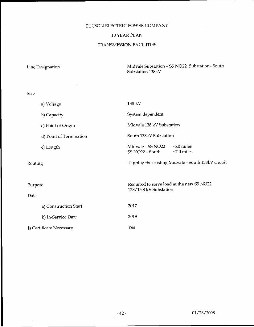
Midvale Substation - SS NO22 Substation- South Substation 138kV
138-kV
System dependent
Midvale 138 kV Substation
South 138kV Substation
Midvale - SS NO22 SS NO22 - South
-6.0 miles -7.0 miles
Tapping the existing Midvale - South 138kV circuit
Required to serve load at the new SS NO22 138/13.8 kV Substation
2017
2019
Yes
- 42 - 01/ 28/ 2008
Line Designation
Size
a) Voltage
b) Capacity
c) Point of Origin
d) Point of Termination
e) Length
TUCSON ELECTRIC POWER COMPANY
10 YEAR PLAN
TRANSMISSION FACILITIES
Routing
Purpose
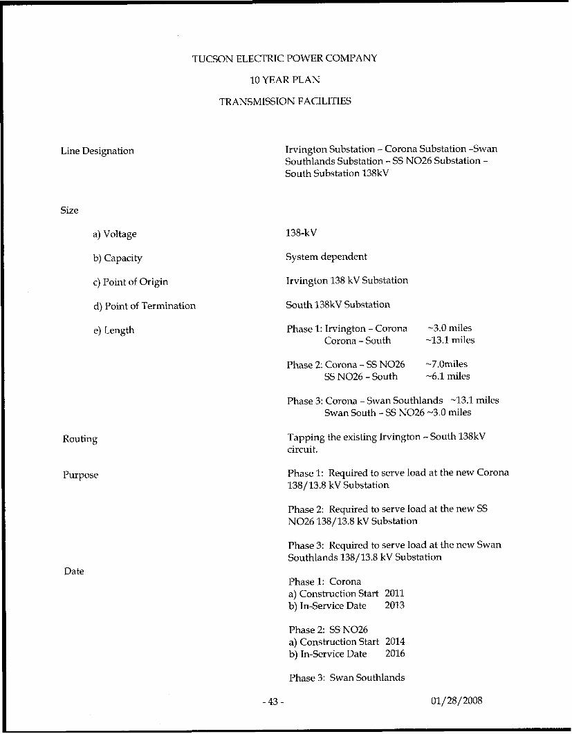
Irvington Substation - Corona Substation -Swan Southlands Substation - SS NO26 Substation - South Substation 138kV
138-kV
System dependent
Irvington 138 kV Substation
South 138kV Substation
Phase 1: Irvington - Corona -3.0 miles Corona - South -13.1 miles
Phase 2 Corona - SS NO26 -7.Omiles -6.1 miles SS NO26 - South
Phase 3: Corona - Swan Southlands -13.1 miles Swan South - SS NO26 -3.0 miles
Tapping the existing Irvington - South 138kV circuit.
Phase 1: Required to serve load at the new Corona 138/13.8 kV Substation
Phase 2: Required to serve load at the new SS NO26 138/13.8 kV Substation
Phase 3: Required to serve load at the new Swan Southlands 138/13.8 kV Substation
Date Phase 1: Corona a) Construction Start 2011 b) In-Service Date 2013
Phase 2: SS NO26 a) Construction Start 2014 b) In-Service Date 2016
Phase 3: Swan Southlands
-43- 01/ 28/ 2008
Is Certificate Necessary
a) Construction Start 2016 b) In-Service Date 2018
Yes
-44 - 01/28/2008
Line Designation
Size
a) Voltage
b) Capacity
c) Point of Origin
d) Point of Termination
e) Length
TUCSON ELECTRIC POWER COMPANY
10 YEAR PLAN
TRANSMISSION FACILITIES
Routing
Purpose
Date
a) Construction Start
b) In-Service Date
Is Certificate Necessary
- 4 5 -
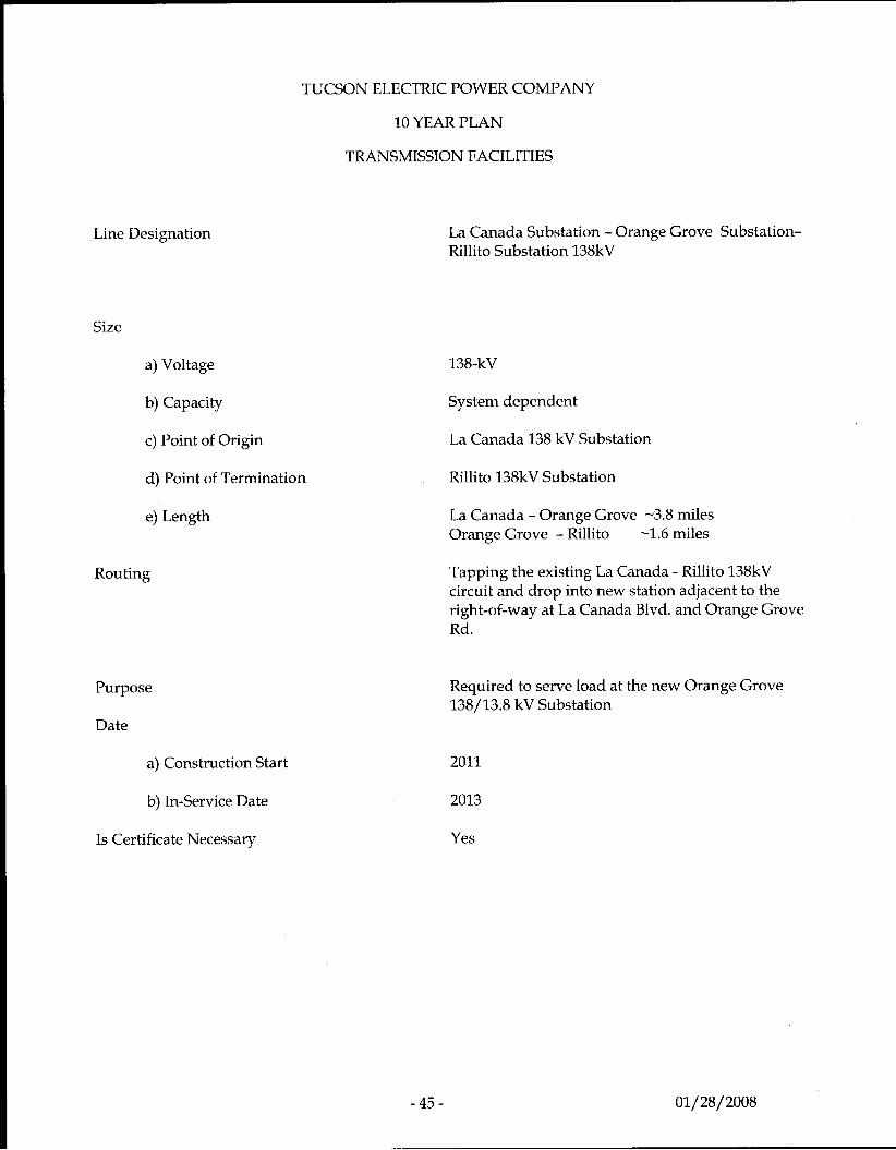
La Canada Substation - Orange Grove Substation- Rillito Substation 138kV
138-kV
System dependent
La Canada 138 kV Substation
Rillito 138kV Substation
La Canada - Orange Grove -3.8 miles Orange Grove - Rillito -1.6 miles
Tapping the existing La Canada - Rillito 138kV circuit and drop into new station adjacent to the right-of-way at La Canada Blvd. and Orange Grove Rd .
Required to serve load at the new Orange Grove 138/13.8 kV Substation
2011
2013
Yes
01/28/ 2008
TUCSON ELECTRIC POWER COMPANY
10 YEAR PLAN
TRANSMISSION FACILITIES
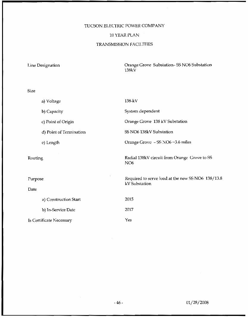
Line Designation Orange Grove Substation- SS NO6 Substation 138kV
Size
a) Voltage
b) Capacity
c) Point of Origin
d) Point of Termination
e) Length
Routing
Purpose
Date
a) Construction Start
b) In-Service Date
Is Certificate Necessary
-46 - 01/28/2008
138-kV
System dependent
Orange Grove 138 kV Substation
SS NO6 138kV Substation
Orange Grove - SS NO6 -3.6 miles
Radial 138kV circuit from Orange Grove to SS NO6
Required to serve load at the new SS NO6 138/13.8 kV Substation
2015
2017
Yes
Line Designation
Size
a) Voltage
b) Capacity
c) Point of Origin
d) Point of Termination
e) Length
TUCSON ELECTRIC POWER COMPANY
10 YEAR PLAN
TRANSMISSION FACILITIES
Routing
Purpose
Date
a) Construction Start
b) In-Service Date
Is Certificate Necessary
-47-
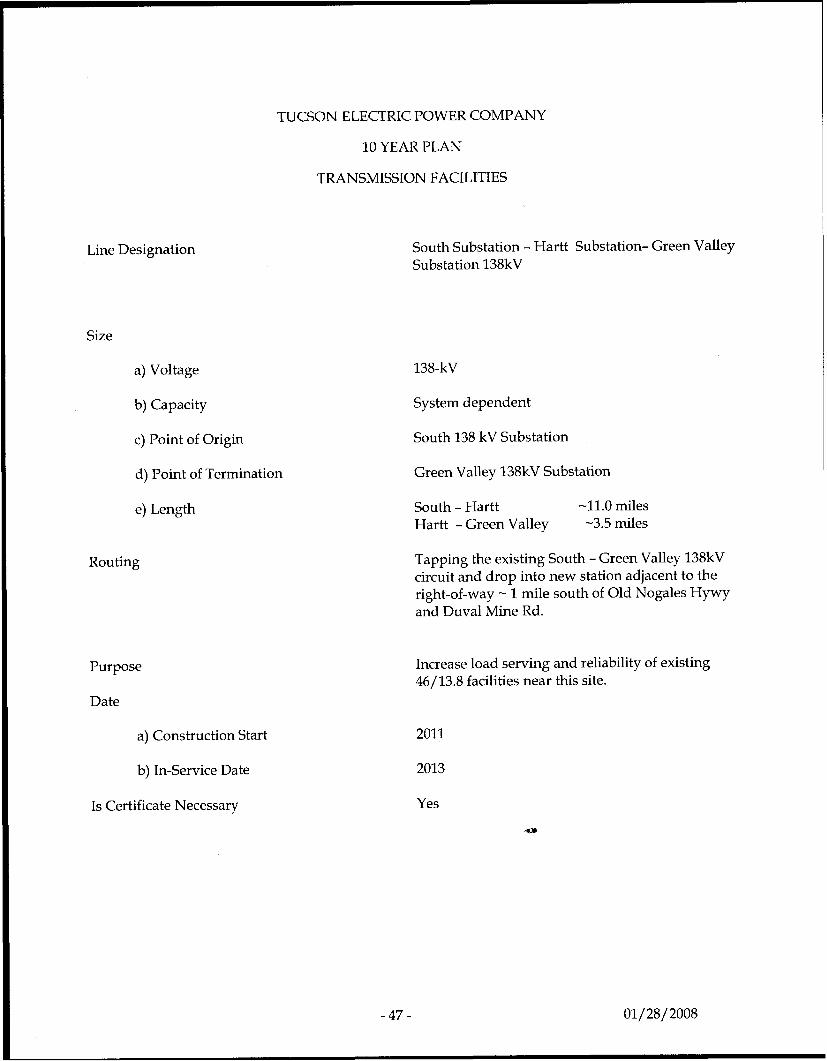
South Substation - Hartt Substation- Green Valley Substation 138kV
138-kV
System dependent
South 138 kV Substation
Green Valley 138kV Substation
South - Hartt -11.0 miles Hartt - Green Valley -3.5 miles
Tapping the existing South - Green Valley 138kV circuit and drop into new station adjacent to the right-of-way - 1 mile south of Old Nogales Hywy and Duval Mine Rd.
Increase load serving and reliability of existing 46/13.8 facilities near this site.
2011
2013
Yes
01/28/2008
Line Designation
Size
a) Voltage
b) Capacity
c) Point of Origin
d) Point of Termination
e) Length
TUCSON ELECTRIC POWER COMPANY
10 YEAR PLAN
TRANSMISSION FACILITIES
Routing
Purpose
Date
a) Construction Start
b) In-Service Date
Is Certificate Necessary
- 4 8 -
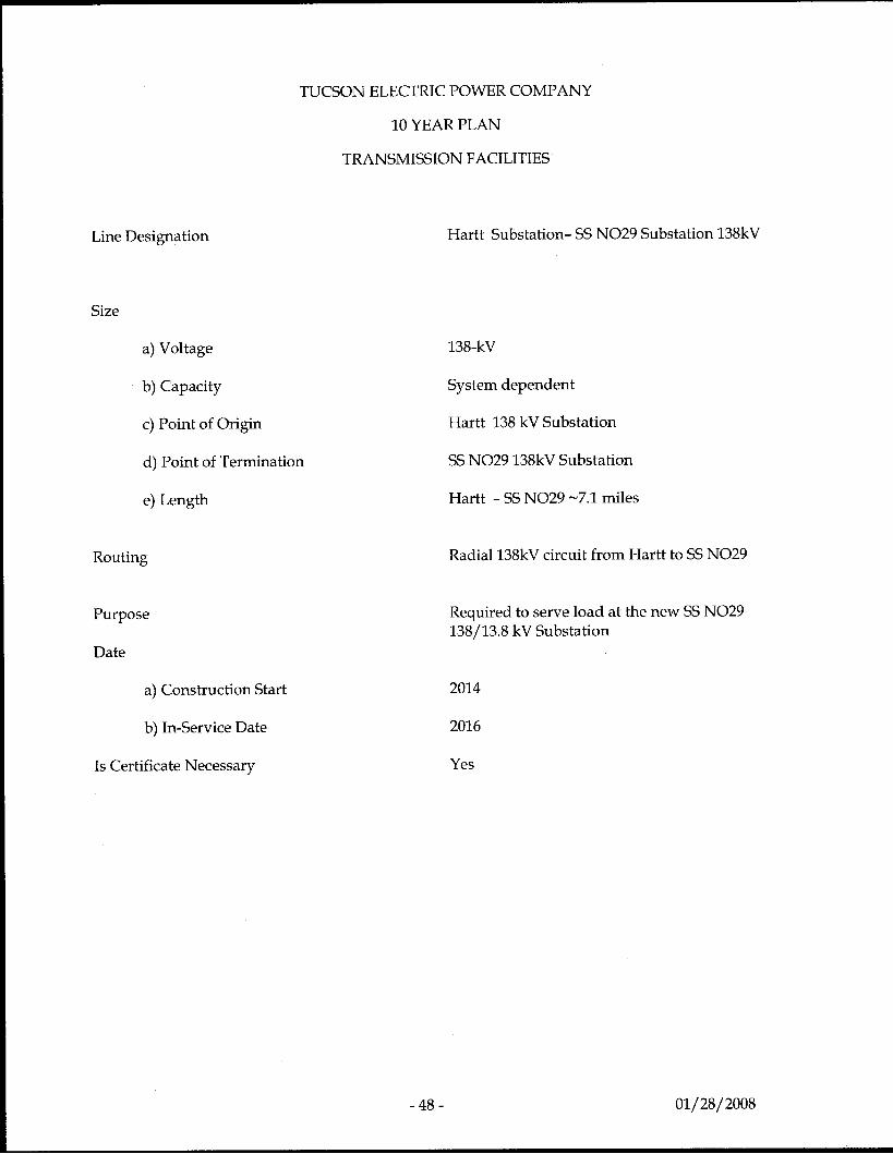
Hartt Substation- SS NO29 Substation 138kV
138-kV
System dependent
Hartt 138 kV Substation
SS NO29 138kV Substation
Hartt - SS NO29 -7.1 miles
Radial 138kV circuit from Hartt to SS NO29
Required to serve load at the new SS NO29 138/13.8 kV Substation
2014
2016
Yes
01/28/2008
Line Designation
Size
a) Voltage
b) Capacity
c) Point of Origin
d) Point of Termination
e) Length
Routing
TUCSON ELECTRIC POWER COMPANY
10 YEAR PLAN
TRANSMISSION FACILITIES
Purpose
Date
a) Construction Start
b) In-Service Date
Is Certificate Necessary
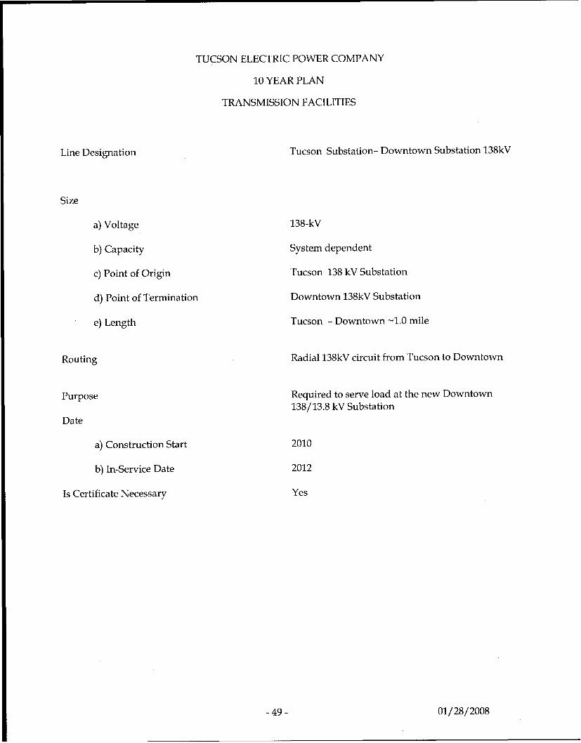
Tucson Substation- Downtown Substation 138kV
138-kV
System dependent
Tucson 138 kV Substation
Downtown 138kV Substation
Tucson - Downtown -1.0 mile
Radial 138kV circuit from Tucson to Downtown
Required to serve load at the new Downtown 138/13.8 kV Substation
2010
2012
Yes
- 4 9 - 01/28/2008
TUCSON ELECTRIC POWER COMPANY
10 YEAR PLAN
TRANSMISSION FACILITIES
Line Designation
Size
a) Voltage
b) Capacity
c) Point of Origin
d) Point of Termination
e) Length
Routing
Purpose
Date
a) Construction Start
b) In-Service Date
Is Certificate Necessary
- 50 - 01/28/ 2008
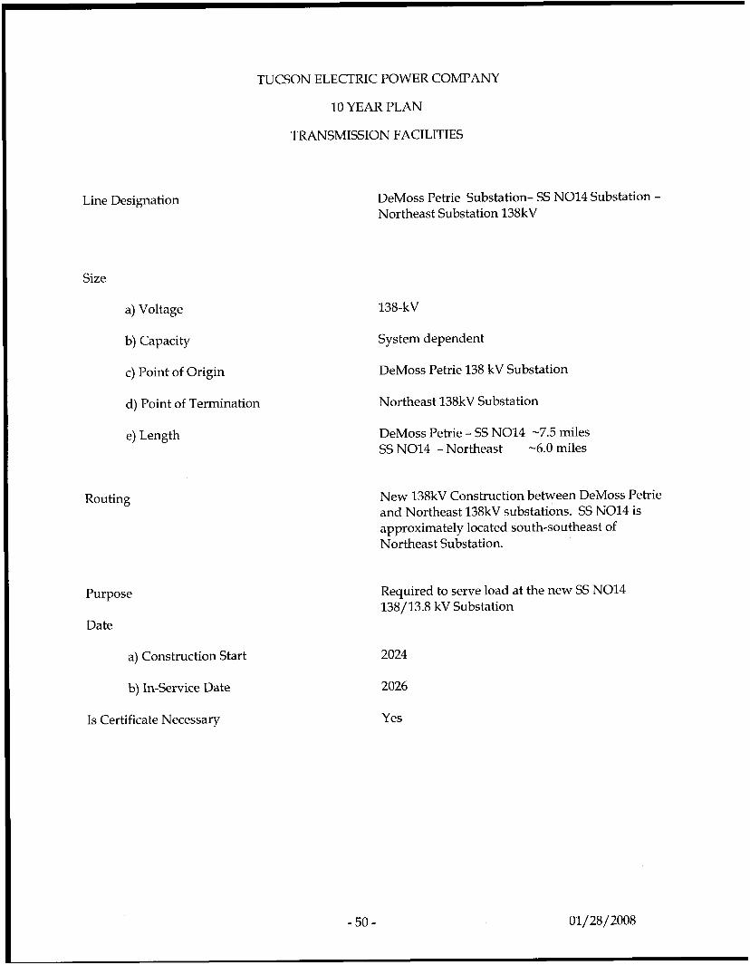
DeMoss Petrie Substation- SS NO14 Substation - Northeast Substation 138kV
138-kV
System dependent
DeMoss Petrie 138 kV Substation
Northeast 138kV Substation
DeMoss Petrie - SS NO14 -7.5 miles SS NO14 - Northeast -6.0 miles
New 138kV Construction between DeMoss Petrie and Northeast 138kV substations. SS NO14 is approximately located south-southeast of Northeast Substation.
Required to serve load at the new SS NO14 138/13.8 kV Substation
2024
2026
Yes
Line Designation
Size
a) Voltage
b) Capacity
c) Point of Origin
d) Point of Termination
e) Length
TUCSON ELECTRIC POWER COMPANY
10 YEAR PLAN
TRANSMISSION FACILITIES
Routing
Purpose
Date
a) Construction Start
b) In-Service Date
Is Certificate Necessary
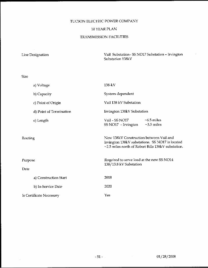
Vail Substation- SS NO17 Substation - Irvington Substation 138kV
138-kV
System dependent
Vaill38 kV Substation
Irvington 138kV Substation
Vail - SS NO17 SS NO17 - Irvington
-6.5 miles -3.5 miles
New 138kV Construction between Vail and Irvington 138kV substations. SS NO17 is located -2.5 miles north of Robert Bills 138kV substation.
Required to serve load at the new SS NO14 138/13.8 kV Substation
2018
2020
Yes
-51 - 01/28/2008
Appendix A
Static VAr Compensator Voltage Stability Studies
-52- 01/ 28/ 2008
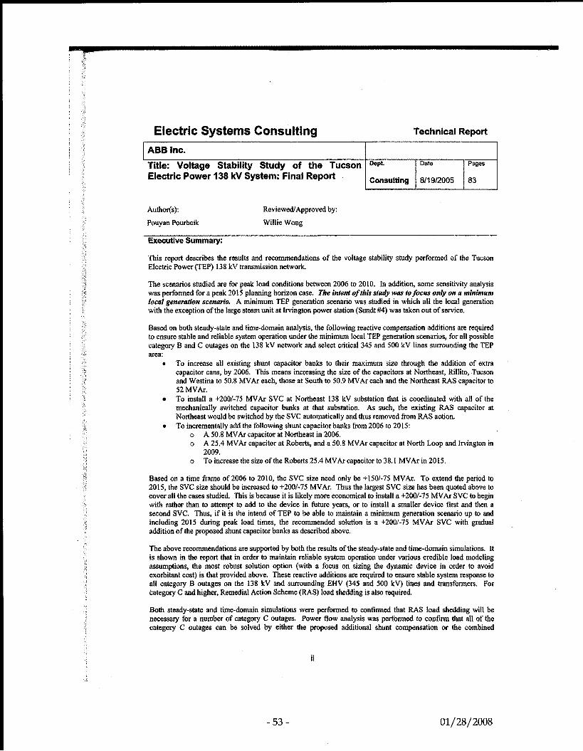
Electric Systems Consulting Technical Report
ABB Inc.
Electric Power 138 kV System: Final Report Title: Voltage Stability Study of the Tucson Oe* Date Pages
Consulting 811 9Q005 83
Author(s):
Pouyan Pourbeik
Reviewed Approved by:
Willie Wong
Executive Summary:
This report describes the results and recommendations of the voltage stability study performed of the Tucson Electric Power (TEP) 138 kV transmission network.
The scenarios studied are for pe& load conditions between 2006 to 2010. In addition, some sensitivity analysis was performed for a peak 2015 planning horizon case. The intent of this struly was tofocw only on a minimum local generrrtion scenario, A minimum TEP generation scenario was studied in which all the local generation with the exception of the large steam unit at Irvington power station (Sundt #4) was taken out of service.
Based on both steady-state and time-domain analysis, the following reactive compensation additions are required to ensure stable and reliable system operation under the minimum local TEP generation scenarios, for all possible category B and C outages on the 138 kV network and select critical 345 and 500 kV lines surrounding the TEP area:
t To increase all existing shunt capacitor banks to their maximum size through the addition of extra capacitor cans, by 2006. This means increasing the size of the capacitors at Northeast, Rillito, Tucson and Westina to 50.8 MVAr each, those at South to 50.9 MVAr each and the Northeast RAS capacitor to 52 MVAr. To install a +200/-75 MVAr SVC at Northeast 138 kV substation that is coordinated with all of the mechanically switched capacitor banks at that substation. As such, the existing RAS capacitor at Northeast would be switched by the SVC automatically and thus removed from RAS action. To incrementally add the following shunt capacitor banks from 2006 to 2015:
o o
o
A 50.8 MVAr capacitor at Northeast in 2006. A 25.4 MVAr capacitor at Roberts, and a 50.8 MVAr capacitor at North Loop and Irvington in 2009. To increase the size of the Roberts 25.4 MVAr capacitor to 38. I MVAr in 2015.
Based on a time frame of 2006 to 2010, the SVC size need only be +150/-75 MVAr. To extend the period to 2015, the SVC size should be increased to +200/-75 MVAr. Thus the largest SVC size has been quoted above to cover all the cases studied. This is because it is likely more economical to install a 4-2001-75 MVAr SVC to begin with rather than to attempt to add to the device in future years, or to install a smaller device first and then a second SVC. Thus, if it is the intend of TEP to be able to maintain a minimum generation scenario up to and including 2015 during peak load times, the recommended solution is a +2001-75 MVAr SVC with gradual addition of the proposed shunt capacitor banks as described above.
The above recommendations are supported by both the results of the steady-state and time-domain simulations. It is shown in the report that in order to maintain reliable system operation under various credible load modeling assumptions, the most robust solution option (with a focus on sizing the dynamic device in order to avoid exorbitant cost) is that provided above. These reactive additions are required to ensure stable system response to all category B outages on the I38 kV and surrounding ENV (345 and 500 kV) lines and transformers. For category C and higher, Remedial Action Scheme (RAS) load shedding is also required.
Both steady-state and time-domain simulations were perfomed to confirmed that RAS load shedding will be necessw for a number of category C outages. Power flow analysis was performed to confirm that all of the category C outages can be solved by either the proposed additional shunt compensation or the combined
ii
- 53 - 01/28/2008
applimtion of this shunt compensation together with an appropriate amount of RAS load shedding and the application of the RAS reactor at South. Although the RAS capacitors at V&l were not used, this is not necessarily an indication that they are not needed for category C and D outages. Here the purpose of the N-2 contingency analysis was simply to illustrate that a solution can be achieved with the combination of RAS (load shedding and reactive devices) and the added reactive compensation. Therefore, we simply found a way to achieve a solution in each case. A more optimal solution may exist with the application of the RAS capacitors. The optimization of the RAS load shedding and reactive devices, for category C and D outages, is outside the scope of this study. Time-domain simulations were also performed for the most onerous category C cases to illustrate that the combination of the additional shunt compensation and RAS load shedding can indeed achieve a stable system response.
Through the N-2 contingency analysis a couple of double contingencies were identified that may warrant further investigation. One of these results in problems in the New Mexico system and the other results in severe voltage depressions in Zone 161. Since both areas are outside the study area being investigated here, no further action was taken for the purposes of this study.
Finally, it should be emphasized again that the above reactive additions are recommended for the purpose of allowing reliable system operation during peak load hours under a TEP minimum local generation scenario. Recently discussions with TEP (since late June, 2005) have identified that the propose minimum generation scenario may not be realizable as early as 2006 due to thermal and other system operating constraints. Thus, reaching the minimum generation scenario may be a more gradual process as other issues are addressed in parallel. As such, the need for the SVC (and possibly its size) as well as the exact timing of phasing in the additional shunt capacitor additions will be impacted by the actual generation dispatch scenarios to be considered. Such determinations require further analysis, and are beyond the scope of this report.
iii
- 54 - 01/ 28/ 2008
Electric Systems Consulting ABB Inc.
Title: Voltage Stability Study of the Tucson Electric Power 138 kV System - Phase 11: Final Report
Technical Report
Author(s):
Pouyan Pourbeik
Reviewed/Approved by:
Willie Wong
Executive Summary:
This report describes the results and recommendations of the Phase I1 voltage stability study performed of the Tucson Electric Power (TEP) 138 kV transmission network.
In 2005, a comprehensive analysis was performed of the TEP system looking at a single generation dispatch scenario - minimum local generation (only Sundt #4 on-line). For this analysis, summer peak load cases were studied for 2006 to 2010. In addition, some sensitivity analysis was performed for a peak 2015 planning horizon case.
Based on detailed steady-state analysis (contingency analysis, PV, QV and OPF) and time-domain analysis, it was found that voltage stability concerns did exist within the TEP system for this minimum generation scenario and that the most robust solution, which would cover all cases through 2015, is a smoothly controlled dynamic reactive device. That is, a +200/-75 MVAr SVC located at Northeast substation and coordinated with four 50 MVAr capacitor banks at the same substation (these shunt banks would be essentially the existing three shunt capacitors at Northeast expanded to 2 x 50.8 MVAr and 52 MVAr, and the addition of a third 50.8 MVAr capacitor). Also, some additional mechanically switched capacitors were recommended at other substations for the purpose of ensuring adequate steady-state voltage profile and stability.
This report describes the time-domain, and some limited steady-state analysis, associated with Phase I1 of this study. After completion of the Phase I work in 2005, TEP proceeded to perform an extensive and comprehensive analysis of the system focusing on thermal and voltage criteria from a steady-state perspective. All N-l and N-2 (essentially N-1-1) cases were investigated. Based on this analysis required minimum local generation scenarios (RLG) were established as well as transmission augmentation and discreet shunt compensation additions in order to address thermal and voltage criteria violations. Also, both SVC and non-SVC cases were investigated. In general, the results of the steady-state contingency analysis (performed by TEP) may be briefly summarized as follows:
For the RLG cases established with the SVC in-service the only non-convergent power flow solutions were a few N-1-1 outages that involved the loss of the SVC as one of the outages'. This is clearly no surprise, since the SVC was established to ensure voltage stability. For the RLG cases without the SVC many N-1-1 cases result in divergent power flows, which is indicative of voltage stability concerns. The RLG in general tends to be less with the SVC in-service thus establishing an additional economic benefit of requiring less of the expensive local generation to be on-line for the purpose of serving load.
Based on these results, the decision has been made to move forward with the SVC option. However, to ensure that the steady-state results are indicative of the expected dynamic performance of the system some further time- domain simulations was needed; that is the purpose of this report and study.
In this study, the RLG cases established by TEP's steady-state analysis were used as a starting point. Then the
' Two other oufages also resulfed in non-convergent power flows. The loss of the Irvingfon - Tucson 138 kV and Nvrfh Loop - West Ins I38 kV and fhe loss of Hidalgo - P Young 345 kV and Springcrville - Luna 34s kV. As shown in previous work (such as the Phase I study) the former of these outages results in radially back-feeding a pocket of load off of the 46 kV network and the lanor is related to prohlems in a neighboring system. Thus, these two oufages were DOC furfher invrsrigafed in this study.
ii
- 55 - 01/28/2008
.. . i
worst N-1 and N-1-1 outages were identified through steady-state anaiysis. These critical outages were then simulated in time-domain. The results of this time domain analysis confms that:
1. The SVC is needed to ensure stability and provided for greater voltage regulation and a faster voltage recovery post-disturbance.
2. The proposed location and size of the SVC is adequate through 2015; that is, at the Northeast 138 kV substation, coordinated with the MSCs at that substation and having a rating of +200/-75 MVAr (as seen at the 138 kV level).
3. The additional proposed shunt capacitor banks (mechanically switched) as included in the TEP RLG cases for the study years is needed for steady-state voltage support.
iii
-56- 01/28/ 2008

![Report on Ichchhapore substation Substation...2014/07/06 · Date:02/02/2018 Report on Ichchhapore substation Substation: SubstationEquipment: 1] PowerTransformer: A](https://img.pdfslide.us/doc/110x75/6082a7423c38c8542368e070/report-on-ichchhapore-substation-substation-20140706-date02022018-report.jpg)