Embed Size (px)
Citation preview

1
TuBAR® Retrofit for
Wayne Ovation
Multi-Point Latch
Copyright © 2012 CompX Security Products. Any companies and/or products referred to herein are marks or registered trademarks of their respective companies owners and/or mark holders.
2
B
C
D
J
F
G
A
E
I
H
K
L
M
TuBAR® Skirt Door
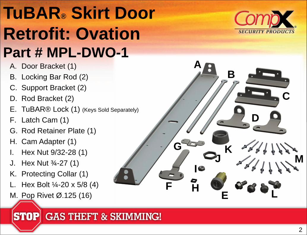
Retrofit: Ovation Part # MPL-DWO-1
A. Door Bracket (1)
B. Locking Bar Rod (2)
C. Support Bracket (2)
D. Rod Bracket (2)
E. TuBAR® Lock (1) (Keys Sold Separately)
F. Latch Cam (1)
G. Rod Retainer Plate (1)
H. Cam Adapter (1)
I. Hex Nut 9/32-28 (1)
J. Hex Nut ¾-27 (1)
K. Protecting Collar (1)
L. Hex Bolt ¼-20 x 5/8 (4)
M. Pop Rivet Ø.125 (16)
3
Figure 3
TuBAR® Skirt Door
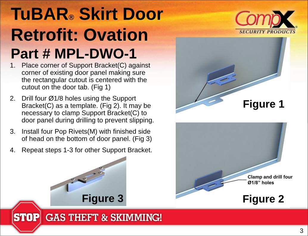
Retrofit: Ovation Part # MPL-DWO-1 1. Place corner of Support Bracket(C) against
corner of existing door panel making sure the rectangular cutout is centered with the cutout on the door tab. (Fig 1)
2. Drill four Ø1/8 holes using the Support Bracket(C) as a template. (Fig 2). It may be necessary to clamp Support Bracket(C) to door panel during drilling to prevent slipping.
3. Install four Pop Rivets(M) with finished side of head on the bottom of door panel. (Fig 3)
4. Repeat steps 1-3 for other Support Bracket.
Figure 1
Figure 2
Clamp and drill four
Ø1/8” holes
4
TuBAR® Skirt Door
Retrofit: Ovation Part # MPL-DWO-1
Figure 5
Drill Ø3/4”Hole
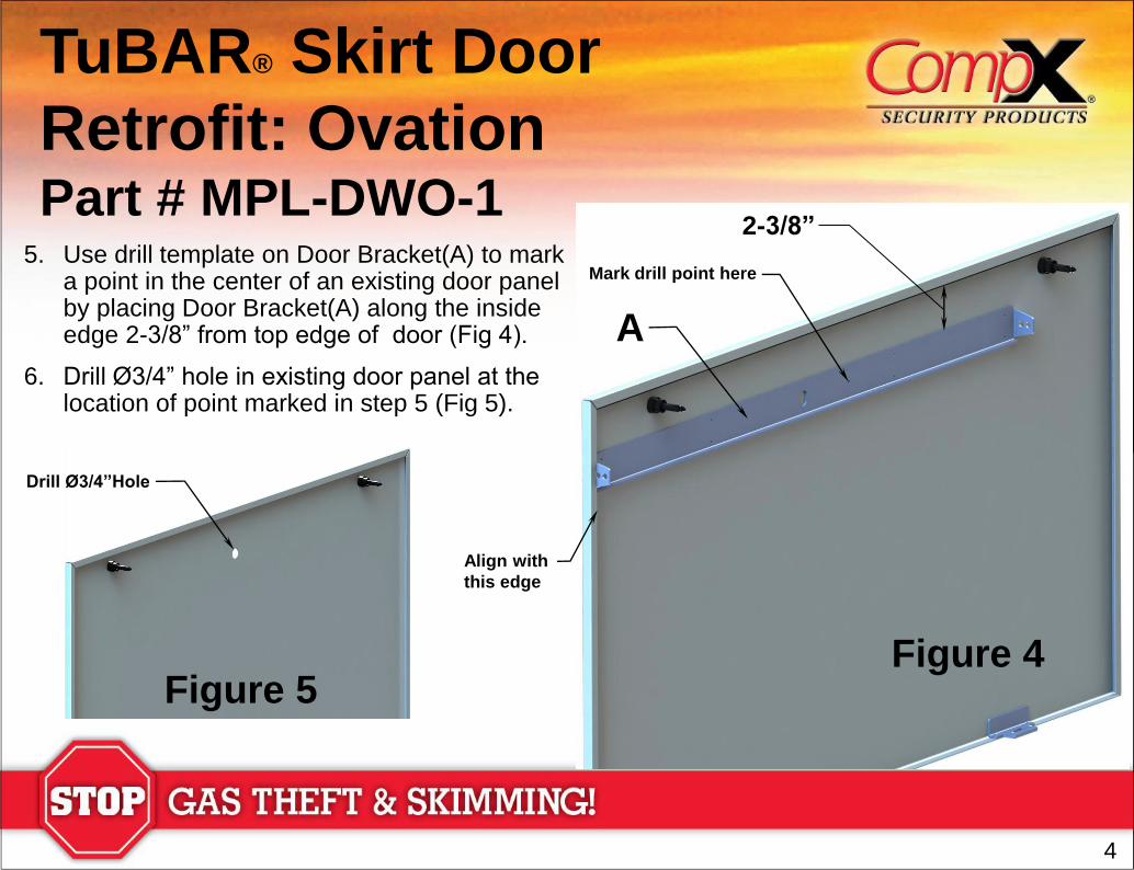
5. Use drill template on Door Bracket(A) to mark a point in the center of an existing door panel by placing Door Bracket(A) along the inside edge 2-3/8” from top edge of door (Fig 4).
6. Drill Ø3/4” hole in existing door panel at the location of point marked in step 5 (Fig 5).
A
2-3/8”
Mark drill point here
Figure 4
Align with
this edge
5
TuBAR® Skirt Door
Retrofit: Ovation Part # MPL-DWO-1
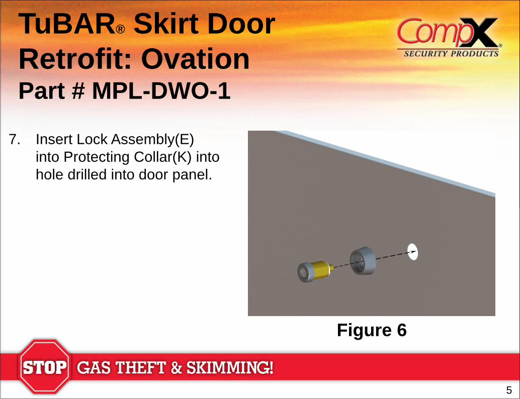
7. Insert Lock Assembly(E)
into Protecting Collar(K) into
hole drilled into door panel.
Figure 6
6
Figure 7
TuBAR® Skirt Door
Retrofit: Ovation Part # MPL-DWO-1
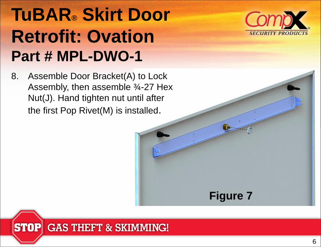
8. Assemble Door Bracket(A) to Lock
Assembly, then assemble ¾-27 Hex
Nut(J). Hand tighten nut until after
the first Pop Rivet(M) is installed.
7
2-3/8”
Figure 8
TuBAR® Skirt Door
Retrofit: Ovation Part # MPL-DWO-1
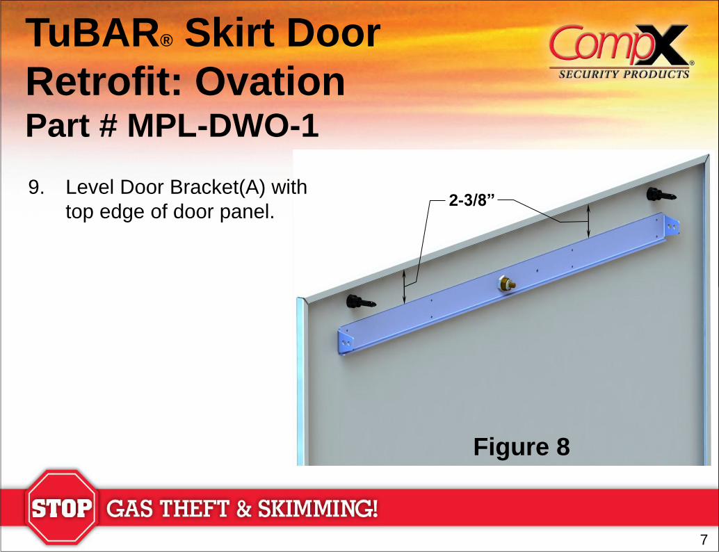
9. Level Door Bracket(A) with
top edge of door panel.
8
TuBAR® Skirt Door
Retrofit: Ovation Part # MPL-DWO-1
Figure 9
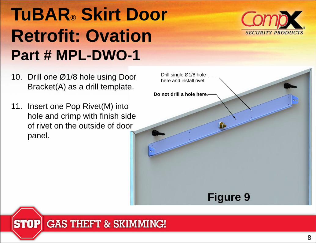
10. Drill one Ø1/8 hole using Door
Bracket(A) as a drill template.
11. Insert one Pop Rivet(M) into
hole and crimp with finish side
of rivet on the outside of door
panel.
Do not drill a hole here.
Drill single Ø1/8 hole
here and install rivet.
9
TuBAR® Skirt Door
Retrofit: Ovation Part # MPL-DWO-1
Figure 10
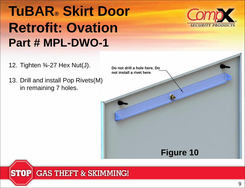
12. Tighten ¾-27 Hex Nut(J).
13. Drill and install Pop Rivets(M)
in remaining 7 holes.
Do not drill a hole here. Do
not install a rivet here.
10
TuBAR® Skirt Door
Retrofit: Ovation Part # MPL-DWO-1
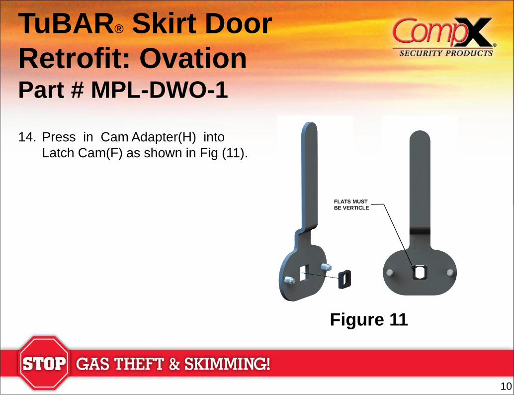
14. Press in Cam Adapter(H) into
Latch Cam(F) as shown in Fig (11).
Figure 11
FLATS MUST
BE VERTICLE
11
Figure 12
TuBAR® Skirt Door
Retrofit: Ovation Part # MPL-DWO-1
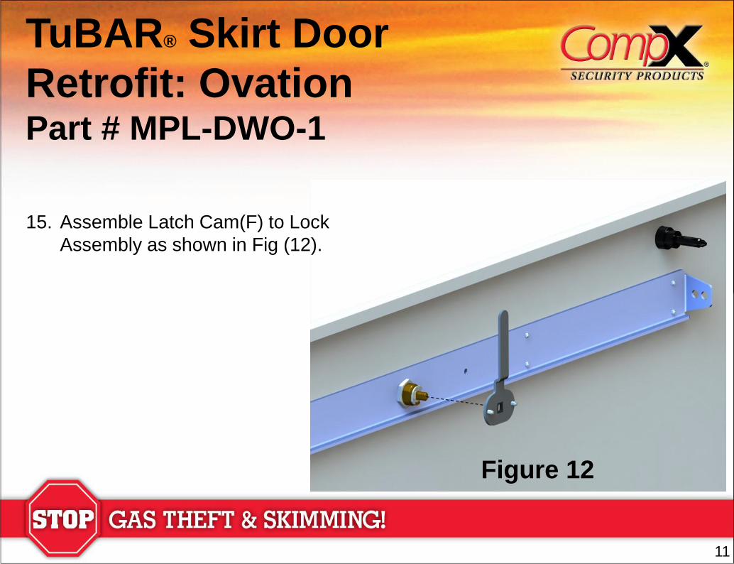
15. Assemble Latch Cam(F) to Lock
Assembly as shown in Fig (12).
12
Figure 13
TuBAR® Skirt Door
Retrofit: Ovation Part # MPL-DWO-1
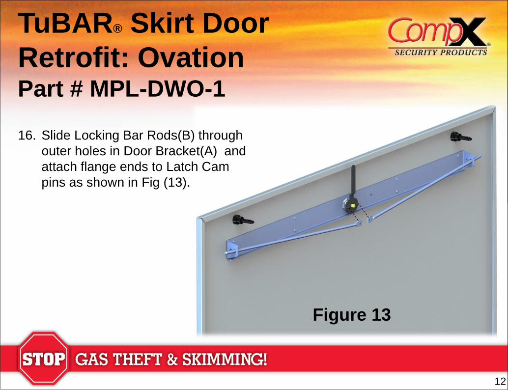
16. Slide Locking Bar Rods(B) through
outer holes in Door Bracket(A) and
attach flange ends to Latch Cam
pins as shown in Fig (13).
13
Figure 14
TuBAR® Skirt Door
Retrofit: Ovation Part # MPL-DWO-1
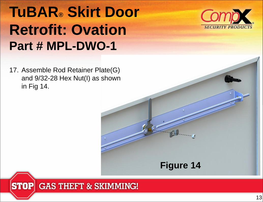
17. Assemble Rod Retainer Plate(G)
and 9/32-28 Hex Nut(I) as shown
in Fig 14.
14
Figure 15
TuBAR® Skirt Door
Retrofit: Ovation Part # MPL-DWO-1
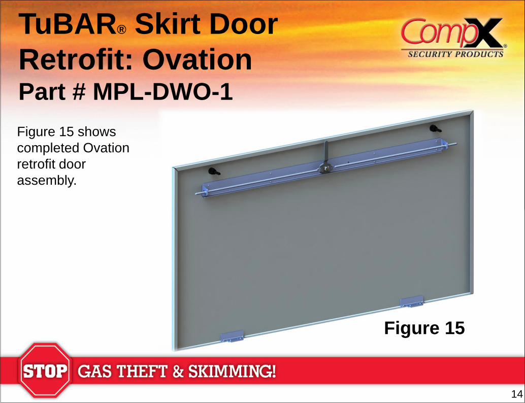
Figure 15 shows
completed Ovation
retrofit door
assembly.
15
18-1/2”
1-1/2”
11/16”
TuBAR® Skirt Door
Retrofit: Ovation Part # MPL-DWO-1
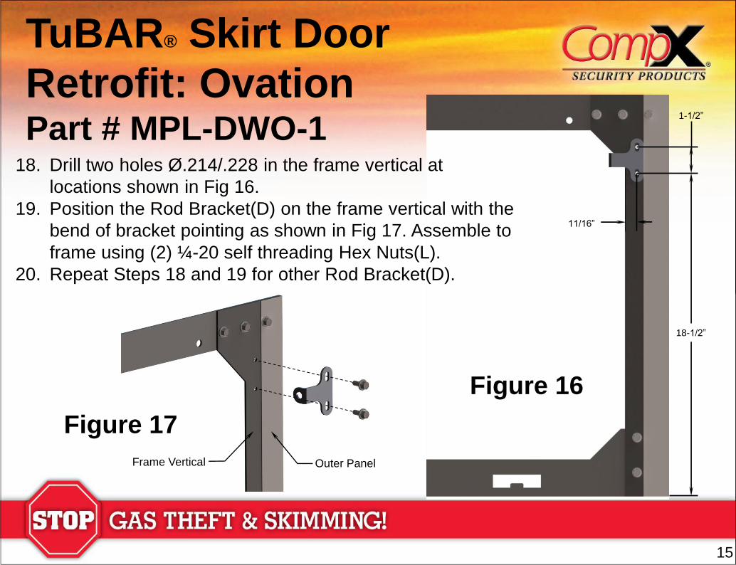
18. Drill two holes Ø.214/.228 in the frame vertical at
locations shown in Fig 16.
19. Position the Rod Bracket(D) on the frame vertical with the
bend of bracket pointing as shown in Fig 17. Assemble to
frame using (2) ¼-20 self threading Hex Nuts(L).
20. Repeat Steps 18 and 19 for other Rod Bracket(D).
Figure 16
Figure 17
Outer Panel Frame Vertical