Embed Size (px)
Citation preview


The MG AuctionWatch website offers an up-to-date, real-time list
of the latest online MG auctions, organised by MG model and category.
Specially-crafted searches for Lucas Parts, Smiths/Jaeger Gauges, Moss Parts, and
MG cars and parts for sale in your local area help you get the most out of eBayTM.
www.mgauctionwatch.com
The definitive guide to
online MG auctions

THE EDITOR John James
Tour of Rutland
I’ve just returned from the TTT 2 Tour of Rutland. The weather was kind to us once we were there and judging from feedback received, everyone enjoyed the weekend. Participants particularly liked the informality of the Tour.
We were very pleased to be joined by Dan Nightingale and James Greig of Love Productions, who chose our Tour to film some of the action for a programme they are making for Channel 4 TV. The photo below shows Ron Benson being interviewed at Barnsdale Gardens, where we had all the cars parked around the perimeter of a field which had been reserved for us.
Tour of Isle of Wight
Planning for next year’s Tour which is being held on the Isle of Wight has now started. We have just had to bring the Tour forward a week. The new dates are 29/30/31 August and 01 September. The reason for this is because, unbeknown to us when we originally set the previous dates, there is a music festival (‘The Bestival’) being held at the same time and the thousands who attend pack the ferries. I have e-mailed the 29 prospective participants who have expressed an interest in the Tour. If you have previously expressed an interest but didn’t receive an e-mail from me, please get in touch straight away. Our allocation of accommodation is 5 single rooms (which have almost certainly all been taken) and 34 double/twin rooms (of which only around 10 remain).
The ‘MG & Riley Parts Dept 1952 Raleigh Low Gravity Cyclemaster Roundsman’.
Some readers may have seen this item which has been for sale on eBay for around £6,000. From a quick scan through the auction lists when the Factory contents were sold off there is apparently no mention of a Cyclemaster. Would be purchasers should verify the provenance of what is being offered for sale by asking the vendor to provide an original Factory photo of the Cyclemaster so that it can be compared with what is being claimed as “cosmetically original”.
Ethanol blend quotas in trouble?
The US Energy Independence and Security Act of 2007 sharply increased how much ethanol that fuel companies must blend into petrol each year. However, the law was passed just before the financial crisis and the shift towards more fuel efficient cars. The result is that the mathematics just do not work since the requirements of the Act can only be met if the fuel companies were to increase the ethanol content in petrol beyond 10%. But in most cases they have refused to go beyond 10%, citing potential damage to engines.
Bollezeele 2014
Some readers will be aware of the wonderful few days experienced for the past 3 years at the Hostellerie Saint-Louis in Bollezeele, France, www.hostelleriesaintlouis.com Bollezeele is a small village about 14 miles outside Dunkerque. The location is also convenient for Calais, some 25 miles, and for people travelling from the North via Belgium or Holland.
TTT 2 subscribers Peter Cole and Gillian Smith have organised these trips for the past three years and have been asked, and agreed, to organise another in 2014. The hotel has only 25 rooms and the aim is to fill all rooms.
As in previous years, this will be a purely social event without any road books or pre arranged meets. Just come along and enjoy the freedom to do your own thing in an area with plenty to suit most people. Not forgetting the wonderful food and wine at the hotel.
Negotiations with the hotel are currently in hand. The proposal for 2014 is to arrive on Tuesday 20th May in time for a welcome reception and dinner then leave on Friday 23rd May after Breakfast. The price per room (2 people) for the 3 days Dinner, Bed and Breakfast package is expected to be in the region of 400 to 472 Euros depending on room choice (Single occupancy rates are available).
Initially please email or send an expression of interest to Peter and Gillian by 30 November 2013. If you wish to discuss anything, please feel free to phone them on either of the numbers below:
Peter Cole and Gillian Smith peter.cole11(at)btopenworld.com {substitute @ for (at)} 01420 85434; 07800950333 10 Princess Drive, Alton, Hants. GU34 1QS
4
Keeping it on the straight and narrow – Aspects that affect
steering.
Eric Worpe delivered a superb presentation at the MGCC ‘T’ Register’s ‘Rebuild’ seminar earlier this year. Eric used flip charts to aid his presentation and I have been working with him to ‘flesh out’ the flip chart notes to produce a series of articles for inclusion in TTT 2.
Eric divided up his presentation into seven headings which he termed as “Seven Deadly Sins”. We dealt with the first ‘Deadly Sin’ i.e.
CHASSIS – is it true? in Issue 19 (August).
In this issue we’ll look in depth at the second ‘Deadly Sin’:
FRONT AXLE GEOMETRY
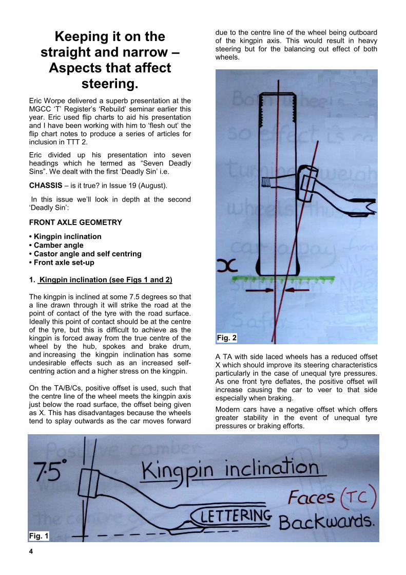
• Kingpin inclination • Camber angle • Castor angle and self centring • Front axle set-up 1. Kingpin inclination (see Figs 1 and 2) The kingpin is inclined at some 7.5 degrees so that a line drawn through it will strike the road at the point of contact of the tyre with the road surface. Ideally this point of contact should be at the centre of the tyre, but this is difficult to achieve as the kingpin is forced away from the true centre of the wheel by the hub, spokes and brake drum, and increasing the kingpin inclination has some undesirable effects such as an increased self-centring action and a higher stress on the kingpin.
On the TA/B/Cs, positive offset is used, such that the centre line of the wheel meets the kingpin axis just below the road surface, the offset being given as X. This has disadvantages because the wheels tend to splay outwards as the car moves forward
due to the centre line of the wheel being outboard of the kingpin axis. This would result in heavy steering but for the balancing out effect of both wheels.
A TA with side laced wheels has a reduced offset X which should improve its steering characteristics particularly in the case of unequal tyre pressures. As one front tyre deflates, the positive offset will increase causing the car to veer to that side especially when braking.
Modern cars have a negative offset which offers greater stability in the event of unequal tyre pressures or braking efforts.
Fig. 1
Fig. 2

Totally T-Type 2, October 2013 5
2. Camber angle The slight incline of the stub axle splays the wheel outwards at the top by 3 degrees to the vertical and this is called a positive Camber angle. Whilst Camber contributes to reducing the offset X (see kingpin inclination diagram - Fig. 2 - under ‘Kingpin inclination section), its main purpose seems rather intriguing and not a little obscure.
If the axis of the stub axle is projected to where it would contact the ground (Fig 3) and the two radii from this pivot point to the top and bottom of the tyre are drawn, a cone is formed.
This cone would tend to roll around its pivot point producing another splaying-out effect on the wheel as the car moves forward and the wheel tries to follow the circumference of the cone. Providing both wheels have the same camber angles, this action is balanced out resulting in no net effect on the steering.
When cornering, the outward weight shift of the car generates a greater splaying-out force (Fig 4) from the outer wheel, which steers the car away from the bend. This results in the driver having to exaggerate the steering effort. This is known as understeer and was considered a safety characteristic at the time.
The 3 degree camber angle is quite high by modern standards and probably originates from the time when most roads were “crowned” to aid drainage. The wheel’s camber would then realise an improved tyre contact footprint as the wheel is more likely to be at 90 degrees to the crown’s circumference.
A 3 degree camber would suit roads having a crown height of just 0.6 inches between the wheels (Fig 5). This suggests that the TABCs are more suited to the narrow, twisty country lanes that predominated in the 1930s. This is indeed fortunate as such roads are more fun to drive on.
Independent suspension is often designed to vary the camber angle to reduce tyre wear and aid adhesion.
Fig. 4
Fig. 5
Fig. 3
Fig. 4

6
Camber angle (continued)
TA/B/Cs set up for competition are sometimes de-cambered by bending the centre of the beam axle (fig 6). This can be achieved by using an hydraulic press (photo 1) A de-cambered axle will have inclined spring mounting pads and these must be compensated for by suitable wedges so that the spring’s eye is aligned with the front eye’s locating pin.
Figure 6 – an illustration of a de-cambered axle.
Photo 1 - a bit of ‘metallic torture’ to de-camber the axle.
3. Castor angle and self centring
The castor angle is made up from two components. The beam axle has an inherent castor angle of 3 degrees. (see Table 1) this is augmented by the slope of the front springs, which for the TA and TB was also 3 degrees.
However, when the rear trunnions were exchanged for shackles on the TC it resulted in an increased spring slope of 5 degrees, giving a total of 8 degrees as opposed to 6 degrees. for the TA and TB. Subsequently wedges of 2.5 degrees were offered to reduce the total castor angle of the TC to 5.5 degrees. (see Table 1 and the illustration at Figure 7)
Table 1
Spring slope Axle Total
TA & TB 3° 3° 6°
TC 5° 3° 8°
TC + taper 5° 3° - 2.5 = 0.5° 5.5°
Figure 7 – an illustration of the “TC + taper” (bottom line of the table) showing how the wedges bring the total castor angle back to 5.5 degrees i.e. 5 degree spring slope plus 3 degrees castor on axle less 2.5 degrees axle wedge.
Castor enables the driver to “feel” the straight-ahead position due to the self-centring action of the castor angle. Fig. 8 shows how the pivot centre line of the wheel intersects the tyre’s footprint ahead of the centre of contact.
Although the castor steering feature is similar to a castor wheel fitted to a trolley, where the wheel’s centre trails behind the pivot axis, an alternative explanation is more suited to the specific geometry of a car.
Figure 8 – showing the self-centring effect
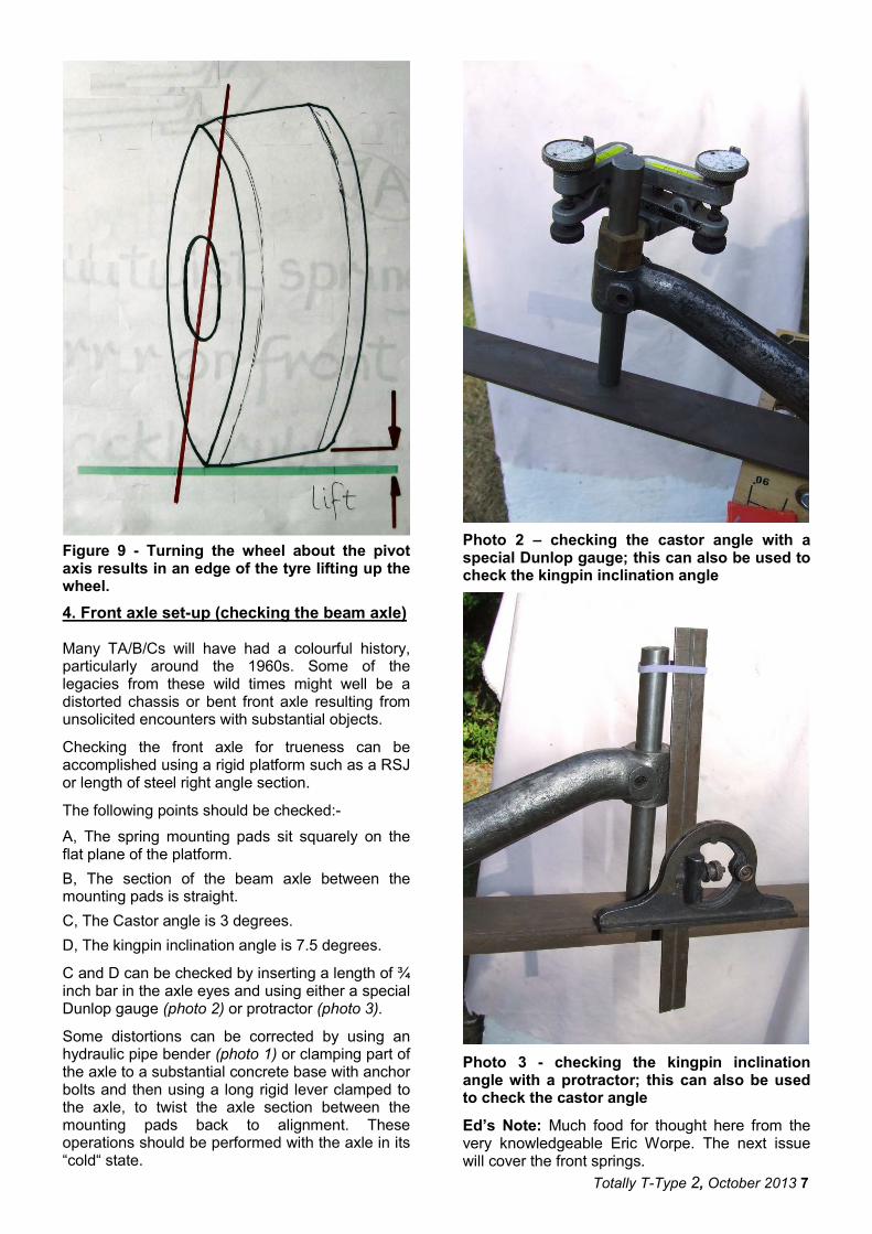
Turning the wheel about the pivot axis results in an edge of the tyre lifting up the wheel (see Figure 9); this can be illustrated by holding a tin can in the hand and holding one’s arm vertically with the can resting on a table. Swivelling the can about the centre axis of one’s arm produces no reactive effect. However, inclining one’s arm to the vertical and swivelling the can should cause one edge of the can to lift.
The weight of the car brings about a “reset” effect, forcing the wheel to return to its lowest (straight ahead) base level. Thus the castor return action is mainly a function of the castor angle, weight of car and width of tyre.
It’s essential that the front wheels posses some self-centring tendency to restore them to the straight-ahead position after deflection by any road undulations, otherwise wheel-wobble or shimmy could occur. Too much castor produces hard steering, whereas too little causes wander.
Totally T-Type 2, October 2013 7
Figure 9 - Turning the wheel about the pivot axis results in an edge of the tyre lifting up the wheel.
4. Front axle set-up (checking the beam axle) Many TA/B/Cs will have had a colourful history, particularly around the 1960s. Some of the legacies from these wild times might well be a distorted chassis or bent front axle resulting from unsolicited encounters with substantial objects.
Checking the front axle for trueness can be accomplished using a rigid platform such as a RSJ or length of steel right angle section.
The following points should be checked:-
A, The spring mounting pads sit squarely on the flat plane of the platform.
B, The section of the beam axle between the mounting pads is straight.
C, The Castor angle is 3 degrees.
D, The kingpin inclination angle is 7.5 degrees.
C and D can be checked by inserting a length of ¾ inch bar in the axle eyes and using either a special Dunlop gauge (photo 2) or protractor (photo 3).
Some distortions can be corrected by using an hydraulic pipe bender (photo 1) or clamping part of the axle to a substantial concrete base with anchor bolts and then using a long rigid lever clamped to the axle, to twist the axle section between the mounting pads back to alignment. These operations should be performed with the axle in its “cold“ state.
Photo 2 – checking the castor angle with a special Dunlop gauge; this can also be used to check the kingpin inclination angle
Photo 3 - checking the kingpin inclination angle with a protractor; this can also be used to check the castor angle
Ed’s Note: Much food for thought here from the very knowledgeable Eric Worpe. The next issue will cover the front springs.

8
MG TD Fuel tank sensor leak
The TD fuel “gauge” is in fact a straight forward float device that operates a “switch” to break (open) the dashboard warning light circuit when the fuel level is sufficiently high. When the fuel level drops to around 2.5 gallons the float activates the switch and the “fuel” warning light illuminates indicating a low level of fuel has been reached.
This simple device requires no maintenance but problems can occur should the fuel seep past one of the float sender unit gaskets.
This “seepage” occurred on my TD fuel tank when I noticed a stain beneath the sender unit, although no fuel had actually been seen dripping out at this stage.
Before commencing any remedial work the first thing to do is to completely drain the fuel tank. Near the centre bottom of the tank is the drain plug that will require a 13/16 AF spanner or socket. At the very bottom right of the tank is the fuel supply take-off fitting, as viewed from the rear of the car.
The fuel integrity at this point is maintained by a fibre washer on the drain plug, this is worth replacing, when refitting the plug, to guard against leaking when the tank is refilled.
With the tank now completely empty, unscrew and disconnect the single wire lamp warning connection that is held in place with a large bakelite screw fitting. Next, undo and remove the outer ring of six slot headed screws and gently pull the complete unit away from the tank. Bear in mind that the float cylinder is some way inside the tank and the original sealant will have hardened. A large circular cork washer (2) fits between the gauge and the tank itself. If this has been untouched for many years it will probably disintegrate, so acquiring a new washer is a good plan as they are readily available.
Tank access for the fuel float and level sensor fittings
The vertical hole, towards the lower bottom of the back of the tank, where the cork washer fits, needs to be cleaned ready for the new replacement.
Take care to guard against foreign bodies entering through this hole otherwise the tank might need to be flushed out.
Fuel level Sender Unit
Sender unit components:
1. Paper washer 6 hole. 1a. Paper washer 3 hole 2. Cork gasket for sender unit 3. Cover fitting plate / Sender unit 4. Six screws for sender unit to fuel tank.
The low fuel tank sender unit (1950) had a 3 screw cover fitting plate (3), whilst later cars seem to have moved to a 6 screw configuration (as in this drawing). The early cover plate, apart from having only 3 screws, also has a pressed indent in its cover that provides some additional rigidity. It is quite possible that the early three screw cover was considered not as “fuel tight” as a six screw option, and hence the move to the improved version at some time after 1950. Although our regular MG parts suppliers all seem to catalogue the sender unit and the large round cork gasket (2), I did not find reference to the paper gasket (1 or 1a) located behind the 3 or 6 hole fitting plates.
As the small paper gasket was the item that had failed it was necessary to fabricate a suitable replacement from heavy paper. After carefully cutting out a replacement paper gasket I coated both sides of the paper edges in a suitable “fuel proof” non setting gasket compound prior to fitting.
Metal cover plate gasket The fuel sender gasket is made of heavy weight drawing or cartridge paper. The size of the gasket is given in approximate inch dimensions but you can always take your metal cover plate to use as an exact former.
Totally T-Type 2, October 2013 9
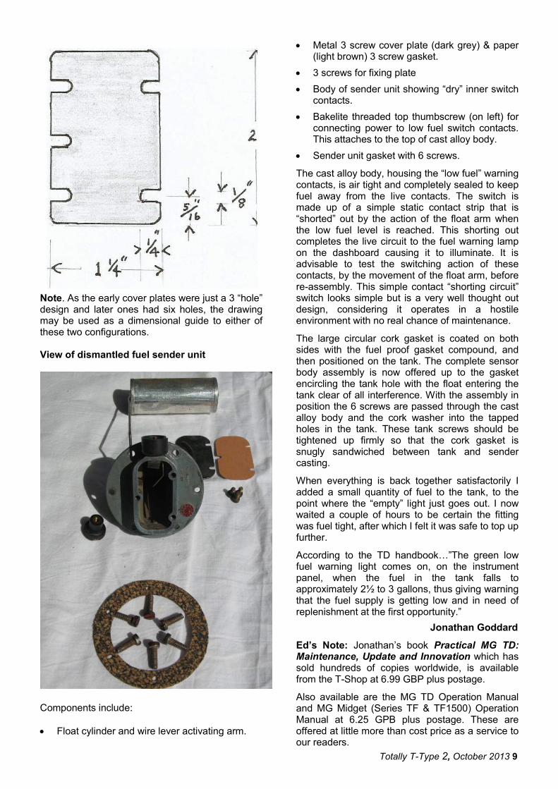
Note. As the early cover plates were just a 3 “hole” design and later ones had six holes, the drawing may be used as a dimensional guide to either of these two configurations. View of dismantled fuel sender unit
Components include:
• Float cylinder and wire lever activating arm.
• Metal 3 screw cover plate (dark grey) & paper (light brown) 3 screw gasket.
• 3 screws for fixing plate
• Body of sender unit showing “dry” inner switch contacts.
• Bakelite threaded top thumbscrew (on left) for connecting power to low fuel switch contacts. This attaches to the top of cast alloy body.
• Sender unit gasket with 6 screws.
The cast alloy body, housing the “low fuel” warning contacts, is air tight and completely sealed to keep fuel away from the live contacts. The switch is made up of a simple static contact strip that is “shorted” out by the action of the float arm when the low fuel level is reached. This shorting out completes the live circuit to the fuel warning lamp on the dashboard causing it to illuminate. It is advisable to test the switching action of these contacts, by the movement of the float arm, before re-assembly. This simple contact “shorting circuit” switch looks simple but is a very well thought out design, considering it operates in a hostile environment with no real chance of maintenance.
The large circular cork gasket is coated on both sides with the fuel proof gasket compound, and then positioned on the tank. The complete sensor body assembly is now offered up to the gasket encircling the tank hole with the float entering the tank clear of all interference. With the assembly in position the 6 screws are passed through the cast alloy body and the cork washer into the tapped holes in the tank. These tank screws should be tightened up firmly so that the cork gasket is snugly sandwiched between tank and sender casting.
When everything is back together satisfactorily I added a small quantity of fuel to the tank, to the point where the “empty” light just goes out. I now waited a couple of hours to be certain the fitting was fuel tight, after which I felt it was safe to top up further.
According to the TD handbook…”The green low fuel warning light comes on, on the instrument panel, when the fuel in the tank falls to approximately 2½ to 3 gallons, thus giving warning that the fuel supply is getting low and in need of replenishment at the first opportunity.”
Jonathan Goddard
Ed’s Note: Jonathan’s book Practical MG TD: Maintenance, Update and Innovation which has sold hundreds of copies worldwide, is available from the T-Shop at 6.99 GBP plus postage.
Also available are the MG TD Operation Manual and MG Midget (Series TF & TF1500) Operation Manual at 6.25 GPB plus postage. These are offered at little more than cost price as a service to our readers.

10
FRONT COVER
As the front cover caption states, the yellow TF is TF9181, the green one is TF9112 and the grey one is TF9097. The respective owners are Ralph Stewart, David Ritchie and Matthew Magilton.
The occasion was the Rob Roy OST (Observed Section Trial) run by the MGA Register of the MGCC of Victoria.
‘Rob Roy’ will be familiar to our friends ‘down under’ but is well worth a few paragraphs of explanation for the benefit of readers elsewhere.
The Rob Roy Hillclimb was, at the time of its construction in the late 1930s, one of only three bitumen surfaced purpose built hillclimbs in the world, the other two being Shelsley Walsh and Prescott (UK). Its origins go back to 1935, when representatives from the then Light Car Club of Australia inspected the property known as Clinton's Pleasure Grounds with a view to establishing a suitable venue for the hillclimb meetings.
The first meeting was run on 1st February 1937, and the track fully bitumenised in 1939. Many meetings were conducted over succeeding years by the Light Car Club, including nine Australian Hillclimb Championships, the very first of which in 1938 was won by Peter Whitehead in his ERA.
In 1962 the area was ravaged by bushfires and the track unfortunately fell into disuse.
In 1992 the MGCC of Victoria was successful in obtaining a ten year lease on the property, and reconstruction began, which involved re-laying the entire surface, improving access roads, and the installation of guard rails on the causeway. The result was a faithful re-creation of the original track.
Even allowing for an immense amount of work put in by MGCC members on a voluntary basis, the costs involved in the project were substantial. To
cover some of these costs, the Friends of Rob Roy was established. A foundation membership, limited to 500, was offered, giving subscribers a ten year period of exclusive free spectator entry, among other benefits. This was fully subscribed very quickly and the bulk of the finance was available in a very short time.
In February 1993 the first "Return to Rob Roy" Historic Meeting was run with outstanding success and a huge spectator attendance. In November 1999 the MGCC ran its eighth Historic and Classic Hillclimb at Rob Roy and the popularity of the event from both competitors and spectators alike has never waned.
The club lease of Rob Roy includes the surrounding hilly paddocks and these are used for the annual Rob Roy OST as well as a "come and try" day for novices where they are introduced to OSTs, Hillclimbs and Motorkhanas.
The OST was introduced to Australia from the UK in the early 1950s and is designed to test the capabilities of the car and driver.
The event consists of cars traversing marked sections of muddy or slippery surfaces and steep or otherwise difficult terrain. The object is to complete the course without stopping and without departing from the marked course or hitting any of the markers.
Points are awarded for the number of markers reached, and the test is to maintain traction under difficult conditions. Speed is not a factor.
A competition event consists of a number of courses. No special equipment is required.
Ed’s Note: The above description of an OST was taken from the website of the MG Car Club of Victoria http://www.mgcc.com.au/mgcc The paragraphs on the history of the Rob Roy HillClimb were taken from and in the main reproduced from the Rob Roy section of the website http://www.mgcc.com.au/robroy/history.shtml
The next two photos were taken at the Rob Roy OST held on 7
th July.
Rob Woodfull putting TD11148 through its paces at the Rob Roy OST in July 2013.
Totally T-Type 2, October 2013 11
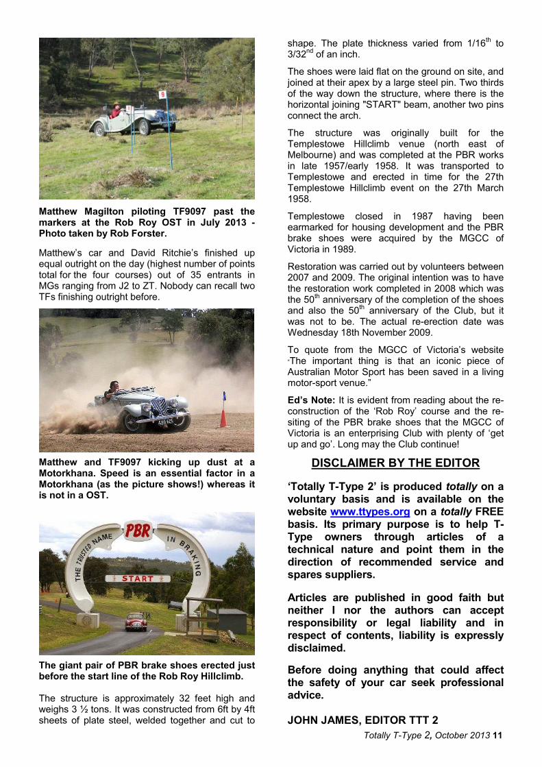
Matthew Magilton piloting TF9097 past the markers at the Rob Roy OST in July 2013 -Photo taken by Rob Forster.
Matthew’s car and David Ritchie’s finished up equal outright on the day (highest number of points total for the four courses) out of 35 entrants in MGs ranging from J2 to ZT. Nobody can recall two TFs finishing outright before.
Matthew and TF9097 kicking up dust at a Motorkhana. Speed is an essential factor in a Motorkhana (as the picture shows!) whereas it is not in a OST.
The giant pair of PBR brake shoes erected just before the start line of the Rob Roy Hillclimb. The structure is approximately 32 feet high and weighs 3 ½ tons. It was constructed from 6ft by 4ft sheets of plate steel, welded together and cut to
shape. The plate thickness varied from 1/16th to
3/32nd of an inch.
The shoes were laid flat on the ground on site, and joined at their apex by a large steel pin. Two thirds of the way down the structure, where there is the horizontal joining "START" beam, another two pins connect the arch.
The structure was originally built for the Templestowe Hillclimb venue (north east of Melbourne) and was completed at the PBR works in late 1957/early 1958. It was transported to Templestowe and erected in time for the 27th Templestowe Hillclimb event on the 27th March 1958.
Templestowe closed in 1987 having been earmarked for housing development and the PBR brake shoes were acquired by the MGCC of Victoria in 1989.
Restoration was carried out by volunteers between 2007 and 2009. The original intention was to have the restoration work completed in 2008 which was the 50
th anniversary of the completion of the shoes
and also the 50th anniversary of the Club, but it
was not to be. The actual re-erection date was Wednesday 18th November 2009.
To quote from the MGCC of Victoria’s website “The important thing is that an iconic piece of Australian Motor Sport has been saved in a living motor-sport venue.”
Ed’s Note: It is evident from reading about the re-construction of the ‘Rob Roy’ course and the re-siting of the PBR brake shoes that the MGCC of Victoria is an enterprising Club with plenty of ‘get up and go’. Long may the Club continue!
DISCLAIMER BY THE EDITOR
‘Totally T-Type 2’ is produced totally on a voluntary basis and is available on the website www.ttypes.org on a totally FREE basis. Its primary purpose is to help T-Type owners through articles of a technical nature and point them in the direction of recommended service and spares suppliers.
Articles are published in good faith but neither I nor the authors can accept responsibility or legal liability and in respect of contents, liability is expressly disclaimed.
Before doing anything that could affect the safety of your car seek professional advice.
JOHN JAMES, EDITOR TTT 2

12
New life for an old wiper motor
As part of the ongoing restoration of TA3120 I had left the wiper motor to near the end as it had been working when I shut the car down 42 years ago. So I was horrified when I opened the rear cover to discover that water had got into the electrics and rusted everything up.
My first reaction was to scrap the unit and source a new or rebuilt one. However none of the usual UK sources had any stock and had no idea when new units would be available, something to do with armature problems in manufacture. Units do turn up on eBay occasionally but vary greatly in condition, and good ones go for serious money. So what to do, especially as working wipers are mandatory if the car is to pass the UK MOT road worthiness test?
The unit itself is a Lucas CWX 12volt L1.
I decided to have another look at the motor, and on applying 12V found it was trying to turn. I’m not an electrical engineer so normally leave this type of unit well alone. However I really had to do something, so rejuvenated it as follows:
Electrics (rear section, photo 1 for exploded view)
Photo 1 – Exploded view of motor.
1. Remove screw from handle, pull handle back and out.
2. Remove two cover holding screws and pull off cover.
3. Noting that each solder connection has two tags, one to grip the wire and the other to solder it, ease each gripping tag open, including the single tag supporting the thin connecting wire between the two stator sections (stator = the two fixed plates on each side of the rotating armature = rotor).
4. Unsolder the two black wires leading from the inside of the connector block where they connect to the brass frame holding the two brushes.
5. Unsolder the thin wire to/from the stator where it is soldered to the same frame as 3 above.
Note that the other wire to/from the stator will have already been unsoldered in 3 above.
6. Move each brush spring back out of the slot and push aside (photo 2). Remove each brush but carefully note side and orientation of each as they are mounted off-centre and need to be a good fit when replaced.
Photo 2 – Brush holding plate.
7. Remove two screws holding the brush plate, carefully lift clear.
8. The rotor will then lift out.
9. (Optional if you plan to service the gearbox next) Remove split pin, washer and spring from the extended wiper spindle on the front of the motor. The spindle will then withdraw easily from the rear.
10. Clean rust from all surfaces with emery paper and/or fine files, then coat with Waxoyl (an oil-based product that partially dries out). I could have used a varnish here but considered that Waxoyl would offer longer term protection against rust.
11. Clean and lubricate rotor shaft.
12. Clean off end of rotor to bare metal, where it touches the brass connector plate on the brush mounting plate.
13. Carefully, with finest emery paper or metal polish clean off the copper elements of the rotor where the brushes contact. Take care to clean only around the elements, not across them, to ensure good brush contact and longer brush life.
14. Clean out the slots between each copper element, then replace rotor.
15. (Optional) You may wish to re-varnish the windings at this point but I chose to leave well alone.
16. Before replacing the brush mounting plate, push each brush spring back and to the rear so that they are locked back and give room to insert the brushes. Check that the ends of the switch contacts are clean and in good condition, and that the inside plate is clean where it touches the end of the rotor shaft.
Totally T-Type 2, October 2013 13
17. (Optional depending on condition of the two side feed wires) Unsolder the two side feed wires and replace with new wire of similar grade and length.
18. Screw plate back on to wiper body.
19. Replace brushes exactly as they came out, then release the holding springs back into their slots.
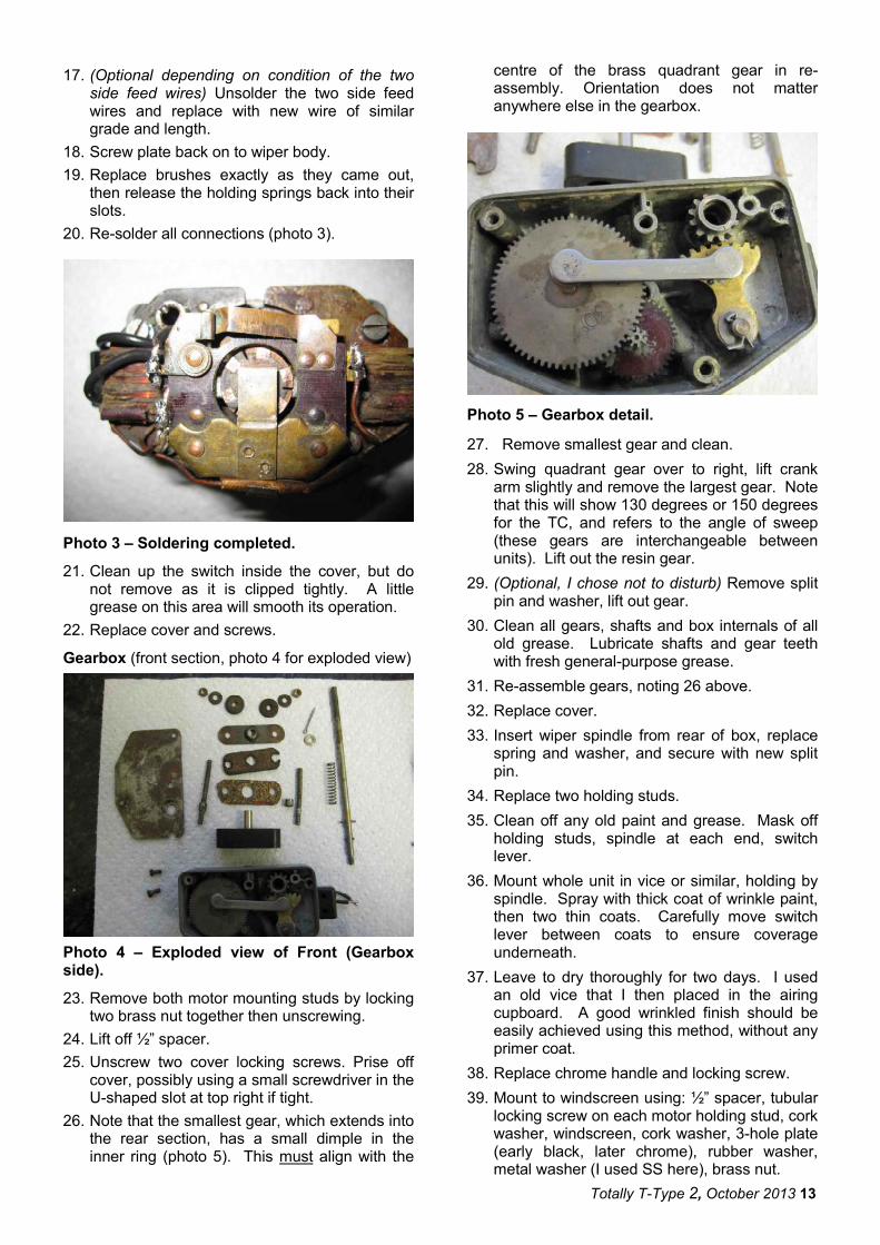
20. Re-solder all connections (photo 3).
Photo 3 – Soldering completed.
21. Clean up the switch inside the cover, but do not remove as it is clipped tightly. A little grease on this area will smooth its operation.
22. Replace cover and screws.
Gearbox (front section, photo 4 for exploded view)
Photo 4 – Exploded view of Front (Gearbox side).
23. Remove both motor mounting studs by locking two brass nut together then unscrewing.
24. Lift off ½” spacer.
25. Unscrew two cover locking screws. Prise off cover, possibly using a small screwdriver in the U-shaped slot at top right if tight.
26. Note that the smallest gear, which extends into the rear section, has a small dimple in the inner ring (photo 5). This must align with the
centre of the brass quadrant gear in re-assembly. Orientation does not matter anywhere else in the gearbox.
Photo 5 – Gearbox detail.
27. Remove smallest gear and clean.
28. Swing quadrant gear over to right, lift crank arm slightly and remove the largest gear. Note that this will show 130 degrees or 150 degrees for the TC, and refers to the angle of sweep (these gears are interchangeable between units). Lift out the resin gear.
29. (Optional, I chose not to disturb) Remove split pin and washer, lift out gear.
30. Clean all gears, shafts and box internals of all old grease. Lubricate shafts and gear teeth with fresh general-purpose grease.
31. Re-assemble gears, noting 26 above.
32. Replace cover.
33. Insert wiper spindle from rear of box, replace spring and washer, and secure with new split pin.
34. Replace two holding studs.
35. Clean off any old paint and grease. Mask off holding studs, spindle at each end, switch lever.
36. Mount whole unit in vice or similar, holding by spindle. Spray with thick coat of wrinkle paint, then two thin coats. Carefully move switch lever between coats to ensure coverage underneath.
37. Leave to dry thoroughly for two days. I used an old vice that I then placed in the airing cupboard. A good wrinkled finish should be easily achieved using this method, without any primer coat.
38. Replace chrome handle and locking screw.
39. Mount to windscreen using: ½” spacer, tubular locking screw on each motor holding stud, cork washer, windscreen, cork washer, 3-hole plate (early black, later chrome), rubber washer, metal washer (I used SS here), brass nut.
14
40. Connect wires, in any order.
41. Stand back, admire, and test operation.
The units are, according to Lucas, designed to run warm. However if one is hot to the touch it is overloading, either due to a dry windscreen, wiper blades that are too large, input/output wires which are overheating internally against coils (cure is 17 above), etc
There is one other feature worth mentioning for maintenance. At top and bottom of the front section there is what looks like a blind rivet. In fact these are spring-loaded balls which seal an oil conduit to the rotor bearing. So a drop or two of a light oil to the top ball every so often, when depressed, will not go amiss. Ian Linton
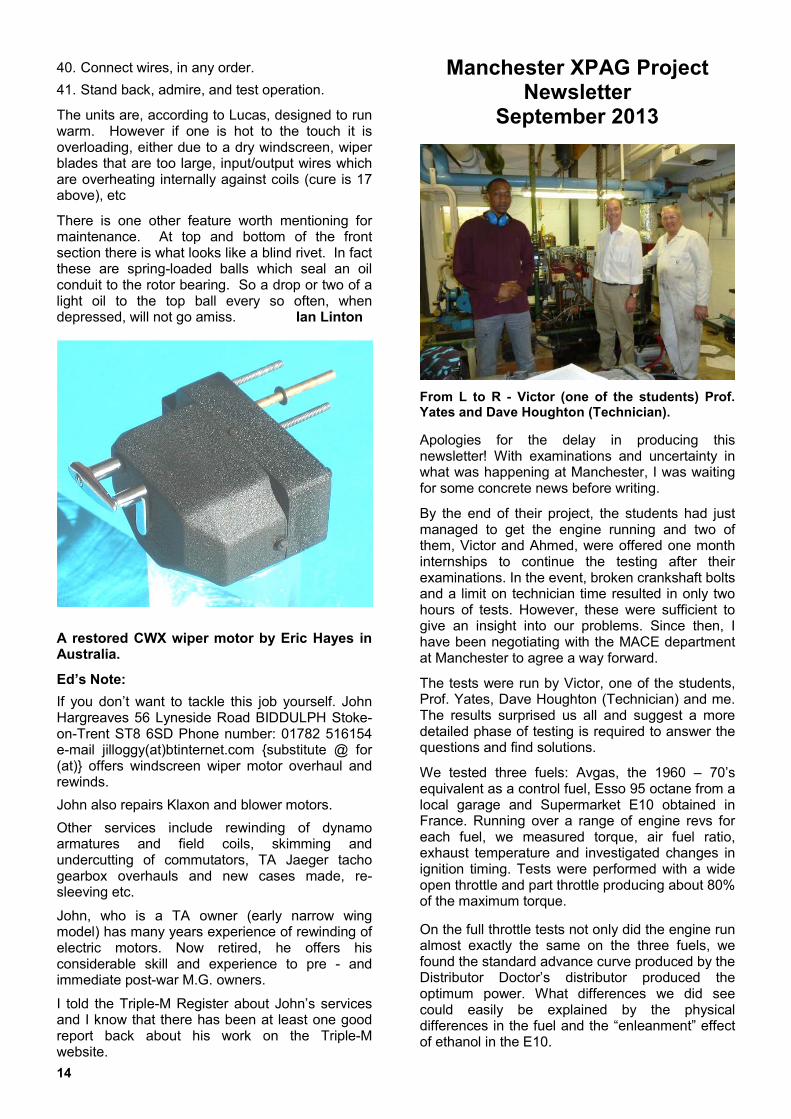
A restored CWX wiper motor by Eric Hayes in Australia.
Ed’s Note:
If you don’t want to tackle this job yourself. John Hargreaves 56 Lyneside Road BIDDULPH Stoke-on-Trent ST8 6SD Phone number: 01782 516154 e-mail jilloggy(at)btinternet.com {substitute @ for (at)} offers windscreen wiper motor overhaul and rewinds.
John also repairs Klaxon and blower motors.
Other services include rewinding of dynamo armatures and field coils, skimming and undercutting of commutators, TA Jaeger tacho gearbox overhauls and new cases made, re-sleeving etc.
John, who is a TA owner (early narrow wing model) has many years experience of rewinding of electric motors. Now retired, he offers his considerable skill and experience to pre - and immediate post-war M.G. owners.
I told the Triple-M Register about John’s services and I know that there has been at least one good report back about his work on the Triple-M website.
Manchester XPAG Project Newsletter
September 2013
From L to R - Victor (one of the students) Prof. Yates and Dave Houghton (Technician).
Apologies for the delay in producing this newsletter! With examinations and uncertainty in what was happening at Manchester, I was waiting for some concrete news before writing.
By the end of their project, the students had just managed to get the engine running and two of them, Victor and Ahmed, were offered one month internships to continue the testing after their examinations. In the event, broken crankshaft bolts and a limit on technician time resulted in only two hours of tests. However, these were sufficient to give an insight into our problems. Since then, I have been negotiating with the MACE department at Manchester to agree a way forward.
The tests were run by Victor, one of the students, Prof. Yates, Dave Houghton (Technician) and me. The results surprised us all and suggest a more detailed phase of testing is required to answer the questions and find solutions.
We tested three fuels: Avgas, the 1960 – 70’s equivalent as a control fuel, Esso 95 octane from a local garage and Supermarket E10 obtained in France. Running over a range of engine revs for each fuel, we measured torque, air fuel ratio, exhaust temperature and investigated changes in ignition timing. Tests were performed with a wide open throttle and part throttle producing about 80% of the maximum torque.
On the full throttle tests not only did the engine run almost exactly the same on the three fuels, we found the standard advance curve produced by the Distributor Doctor’s distributor produced the optimum power. What differences we did see could easily be explained by the physical differences in the fuel and the “enleanment” effect of ethanol in the E10.

Totally T-Type 2, October 2013 15
The part throttle tests gave a different story, which is not obvious when you look at the torque curves. To achieve these values we had to WEAKEN the mixture of the Avgas by 2 flats on the carburettor relative to the full throttle setting and RICHEN it by 6 – 7 flats from the Avgas setting for the Esso and E10.
In other words, fuels that behaved identically on full throttle ran differently on part throttle - modern fuels running significantly weaker than Avgas, our control fuel.
This effect is very worrying. Have your car tuned on a rolling road, at full throttle, then drive it away on part throttle and it will run weak and hot! The problems we are experiencing with modern fuel are real and elusive.
There are two possible explanations, evaporation in the carburettor, changing the mixture or differences in combustion. Unfortunately, the measurements we took were insufficient to give the answers, hence the need for further test.
Paul Ireland
Ed’s Note: Very worrying indeed! In discussion with Paul I have said that lack of money should not be a bar to further research. Further research is potentially costly but the funding must be found. Whilst I have pledged further financial support on behalf of readers there are other funding avenues which need to be explored. You can be assured that Paul is ‘on the case!’
Bits and Pieces
Plenty to report under this heading for this issue; indeed, some of the items could in fact be stand alone articles in their own right.
REAR SPRINGS FOR TD & TF
First out of the traps is news of the forthcoming availability of newly manufactured rear springs for the TD and TF models. I have put in an order for six (6) pairs of TD rear springs and six (6) pairs of TF springs. I am still awaiting confirmation of the price, but I have been given an indication that it will be £105 plus VAT per spring, plus delivery. The transaction will be directly between the motor spring supplier and the buyer. I have no pecuniary interest in this little venture (apart from the fact that it is actually costing me money in sending an original spring to the spring maker!)
The original thickness of each of the seven leafs (I refuse to call them leaves!) was 7/32 inches. This thickness is no longer available so the proposal is to use ¼ inch for each of the five top leafs and 3/16 inch for the bottom two leafs. This will result (I am told) in a negligible difference of 50 thou between the original and the re-manufactured springs and should also make for a slightly softer ride than would be the case if seven x ¼ inch leafs were used.
The springs will be supplied with the two clips (which attach to number 4 leaf) but not the pads for the clips or the nut/bolt/washer and tube which secures these pads. They will be fitted with silentbloc bushes at the front ‘eye’ and the leafs will be drilled to accept the interleaf pads but these will not be supplied. These are available in rubber from suppliers such NTG Services or the Octagon Car Club and are also available in Nylatron from myself.
There might be cheaper springs on the market (and I have no idea where they are made) but the springs on offer are Made in England by an old established motor spring maker from EN45, a silicon-manganese-carbon alloy steel, which is a recommended steel for suspension springs.
By the time this issue of the magazine is on the website I expect to have a firm price and a reasonable idea of the completion date. If you wish to express an interest please contact me via the website contact form or e-mail to the following address jj(at)octagon.fsbusiness.co.uk {please substitute @ for (at)}.
Oil Seal UK
Oil Seal UK http://www.oilsealuk.co.uk is a company run by Jonathan Welch. Jonathan specialises in oil seals for classic vehicles and also has a small stock of popular bearings for vehicle applications. Jonathan is a TC and PA owner and will be pleased to assist you - Tel: 01480 462611.
16
MG TF EASY FIT STAINLESS STEEL BONNET SUPPORTS
Here’s another quality product from Alan Atkins (If you remember, Alan wrote the articles about his poly-carbonate plastic sidescreens for the TD which appeared in Issues 4 and 5 of TTT 2 – these have been supplied to readers around the world).
The bonnet supports for the TF (as with those manufactured by Alan for the TD) allow the bonnet lids to be raised together, which gives easy access to the engine compartment when required. There is no drilling involved since existing bolt fastenings of the side panels to wings are used. The support panels can be set up in about 30 minutes and detailed fixing instructions are supplied with each kit. The supports fold away when not required. The following photos give a good idea of the installation:
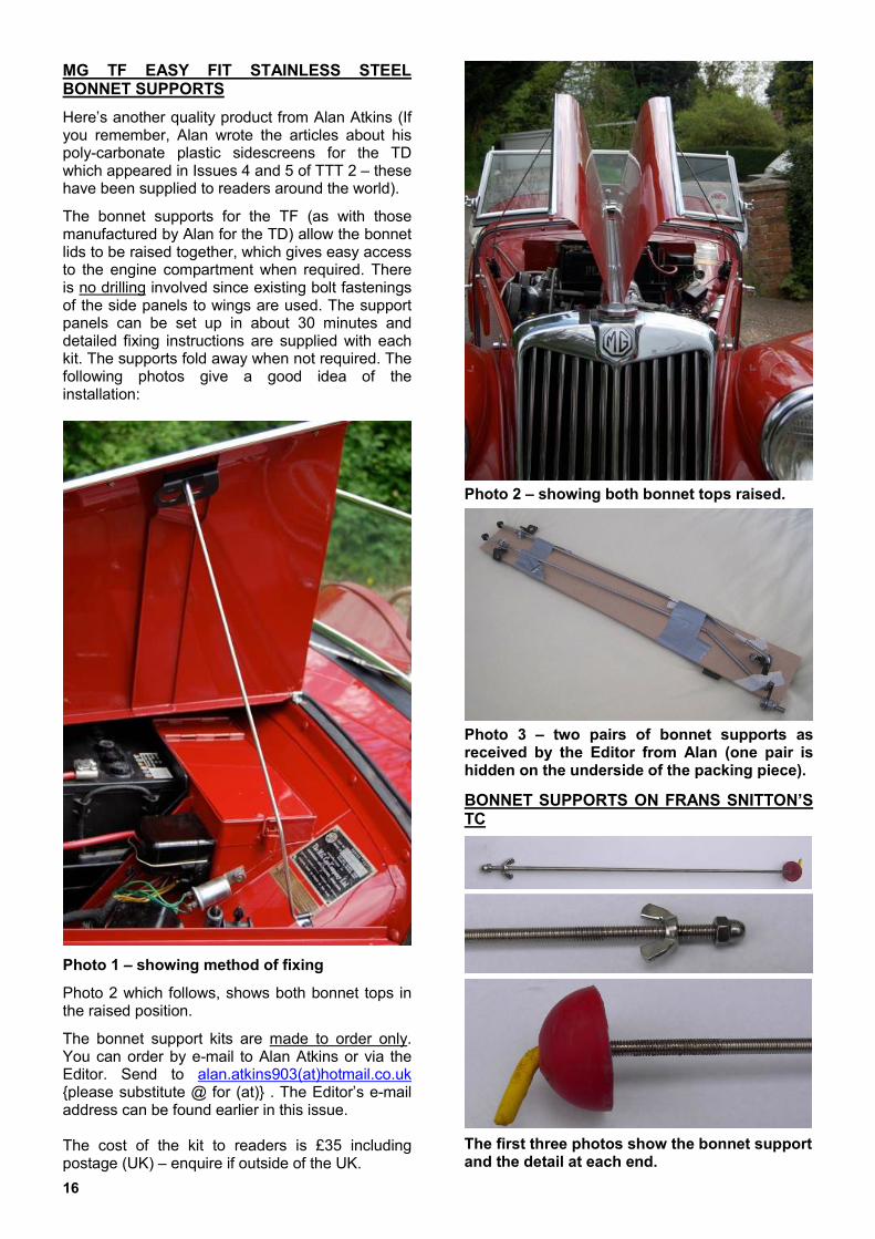
Photo 1 – showing method of fixing
Photo 2 which follows, shows both bonnet tops in the raised position.
The bonnet support kits are made to order only. You can order by e-mail to Alan Atkins or via the Editor. Send to alan.atkins903(at)hotmail.co.uk {please substitute @ for (at)} . The Editor’s e-mail address can be found earlier in this issue. The cost of the kit to readers is £35 including postage (UK) – enquire if outside of the UK.
Photo 2 – showing both bonnet tops raised.
Photo 3 – two pairs of bonnet supports as received by the Editor from Alan (one pair is hidden on the underside of the packing piece).
BONNET SUPPORTS ON FRANS SNITTON’S TC
The first three photos show the bonnet support and the detail at each end.

Totally T-Type 2, October 2013 17
Photos 4 & 5 showing bracket on bulkhead and method of fixing.
Photo 6 – a rubber ball cut in half makes a useful “cushion” against the locating point on the bonnet side.
Photo 7 - Frans trying out his newly restored TC in The Netherlands.
MOSS OIL FILTER CONVERSION
On my 1951 TD, I have a Moss oil filter conversion which allows me to unscrew the bottom and fit a new filter element. I expect many of you have this too. Ed’s Note: It’s a clever mod. (also sold by NTG).
For a while now I have had a niggly wee oil leak…. nothing serious and I thought it was just a blow-back from the front end. However I had a close look and discovered that there was oil gathering on top of the filter. I cleaned it off and then started the engine to see if anything happened; sure enough, a little seepage of oil from just under the pipe connection. I changed the copper gaskets - no difference, so I removed the filter and cleaned off the paint in the offending area. The weld looked well done with no apparent flaws – however, when I pressurised the canister, there was a leakage around about a third of the weld where it met the canister top! Otherwise it was invisible to the naked eye.
Here is a pic - sorry it is a bit out of focus, I cannot go back and retake it, as it is now all re-welded, and repaired. The arrow shows where it was leaking. I am glad I found this in the garage and not out on the open road where it could have got much worse. Maybe you should just check yours too? Cheers! Erik Benson
Hagerty Insurance
We have arranged a discount for our UK readers with Hagerty Insurance. To qualify for this offer, please call Hagerty on 0844 8241130 and quote
the promotional code CCTTT.
Whilst in conversation with participants on the Tour of Rutland it was evident that quite a few of them had taken advantage of the offer and switched to Hagerty. One TB owner said that he had saved over £80. A TF owner, (proper TF!) wrote to me recently as follows:
“I have recently changed my insurance to Hagerty for my TF 1500 and was really impressed with how I was dealt with and the cost. They are also going to insure my MG Midget 1275 next year (I had already insured it for the year with Lancaster) but Hagerty will do a very good deal for 2 cars”.
18
Classic Car of the Year 2013
This award which is being sponsored by Lancaster Insurance will be given to the classic which receives the most votes from members of the public. If you go to http://www.ccoty.co.uk you can find more details.
Chris Parkhurst’s very original TC has made it to the top 30 cars from thousands of entries. If you would like to see a TC voted Classic Car of the Year just go to the above website and click the ‘Vote Now’ button. Voting ends on 27
th September.
Heat Shields for the TF (and TB/TC).
The three TF heat shields advertised in the last issue sold very quickly; two went to Australia.
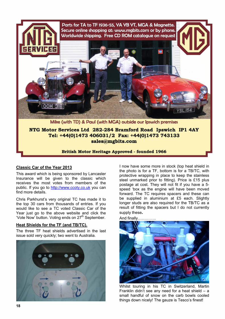
I now have some more in stock (top heat shield in the photo is for a TF, bottom is for a TB/TC, with protective wrapping in place to keep the stainless steel unmarked prior to fitting). Price is £15 plus postage at cost. They will not fit if you have a 5-speed ‘box as the engine will have been moved forward. The TC requires spacers and these can be supplied in aluminium at £5 each. Slightly longer studs are also required for the TB/TC as a result of fitting the spacers but I do not currently
supply these.
And finally…………..
Whilst touring in his TC in Switzerland, Martin Franklin didn’t see any need for a heat shield – a small handful of snow on the carb bowls cooled things down nicely! The gauze is Tesco’s finest!
Totally T-Type 2, October 2013 19
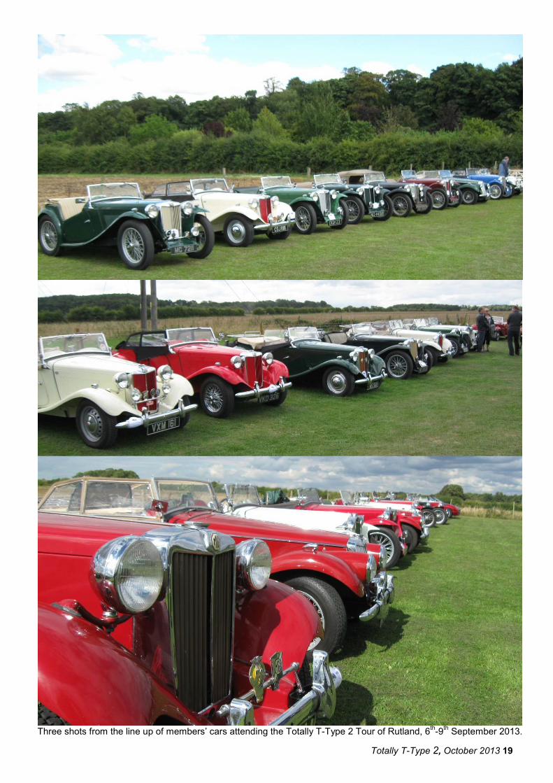
Three shots from the line up of members’ cars attending the Totally T-Type 2 Tour of Rutland, 6
th-9
th September 2013.

20
Two photographs submitted to us via the MG T-Types Facebook page at http://www.facebook.com/mgttypes. Above: Guido de Temmerman’s TC on its way from Belgium to the European Event of the Year in Aviemore,
Scotland. Below: Simon Turner’s ’47 TC.